JP4758985B2 - Distal wire stop device - Google Patents
Distal wire stop device Download PDFInfo
- Publication number
- JP4758985B2 JP4758985B2 JP2007509454A JP2007509454A JP4758985B2 JP 4758985 B2 JP4758985 B2 JP 4758985B2 JP 2007509454 A JP2007509454 A JP 2007509454A JP 2007509454 A JP2007509454 A JP 2007509454A JP 4758985 B2 JP4758985 B2 JP 4758985B2
- Authority
- JP
- Japan
- Prior art keywords
- wire guide
- wire
- tubular member
- distal
- proximal
- Prior art date
- Legal status (The legal status is an assumption and is not a legal conclusion. Google has not performed a legal analysis and makes no representation as to the accuracy of the status listed.)
- Expired - Fee Related
Links
- 238000011282 treatment Methods 0.000 claims description 81
- 239000003550 marker Substances 0.000 claims description 37
- 239000000463 material Substances 0.000 claims description 34
- 230000033001 locomotion Effects 0.000 claims description 11
- 210000004204 blood vessel Anatomy 0.000 claims description 8
- 238000004873 anchoring Methods 0.000 claims 2
- 230000007423 decrease Effects 0.000 claims 2
- 238000000034 method Methods 0.000 description 160
- 210000000013 bile duct Anatomy 0.000 description 26
- 230000008878 coupling Effects 0.000 description 26
- 238000010168 coupling process Methods 0.000 description 26
- 238000005859 coupling reaction Methods 0.000 description 26
- 210000005070 sphincter Anatomy 0.000 description 19
- 210000000232 gallbladder Anatomy 0.000 description 17
- 210000001953 common bile duct Anatomy 0.000 description 14
- 230000007246 mechanism Effects 0.000 description 13
- 208000031481 Pathologic Constriction Diseases 0.000 description 12
- 230000006870 function Effects 0.000 description 12
- 230000010339 dilation Effects 0.000 description 11
- 230000036262 stenosis Effects 0.000 description 11
- 208000037804 stenosis Diseases 0.000 description 11
- BASFCYQUMIYNBI-UHFFFAOYSA-N platinum Chemical compound [Pt] BASFCYQUMIYNBI-UHFFFAOYSA-N 0.000 description 10
- 230000000007 visual effect Effects 0.000 description 10
- 238000001574 biopsy Methods 0.000 description 9
- 238000002627 tracheal intubation Methods 0.000 description 9
- 238000002594 fluoroscopy Methods 0.000 description 8
- 239000002872 contrast media Substances 0.000 description 7
- 238000002428 photodynamic therapy Methods 0.000 description 7
- 210000002784 stomach Anatomy 0.000 description 7
- 239000003814 drug Substances 0.000 description 6
- 238000007459 endoscopic retrograde cholangiopancreatography Methods 0.000 description 6
- 210000003238 esophagus Anatomy 0.000 description 6
- 238000000605 extraction Methods 0.000 description 6
- 238000003384 imaging method Methods 0.000 description 6
- 229910052751 metal Inorganic materials 0.000 description 6
- 239000002184 metal Substances 0.000 description 6
- 239000004033 plastic Substances 0.000 description 6
- 229920003023 plastic Polymers 0.000 description 6
- 230000007723 transport mechanism Effects 0.000 description 6
- 208000000289 Esophageal Achalasia Diseases 0.000 description 5
- 239000004606 Fillers/Extenders Substances 0.000 description 5
- 206010030136 Oesophageal achalasia Diseases 0.000 description 5
- 201000000621 achalasia Diseases 0.000 description 5
- 230000009471 action Effects 0.000 description 5
- 230000008901 benefit Effects 0.000 description 5
- 230000008859 change Effects 0.000 description 5
- 239000011248 coating agent Substances 0.000 description 5
- 238000000576 coating method Methods 0.000 description 5
- 229910052741 iridium Inorganic materials 0.000 description 5
- GKOZUEZYRPOHIO-UHFFFAOYSA-N iridium atom Chemical compound [Ir] GKOZUEZYRPOHIO-UHFFFAOYSA-N 0.000 description 5
- 210000002445 nipple Anatomy 0.000 description 5
- 210000000277 pancreatic duct Anatomy 0.000 description 5
- 229910052697 platinum Inorganic materials 0.000 description 5
- 230000008569 process Effects 0.000 description 5
- 230000005855 radiation Effects 0.000 description 5
- 230000003014 reinforcing effect Effects 0.000 description 5
- 238000002271 resection Methods 0.000 description 5
- 238000002560 therapeutic procedure Methods 0.000 description 5
- 210000001519 tissue Anatomy 0.000 description 5
- 230000002792 vascular Effects 0.000 description 5
- 208000018672 Dilatation Diseases 0.000 description 4
- 210000003445 biliary tract Anatomy 0.000 description 4
- 238000002725 brachytherapy Methods 0.000 description 4
- 238000013213 extrapolation Methods 0.000 description 4
- 210000000214 mouth Anatomy 0.000 description 4
- 210000000056 organ Anatomy 0.000 description 4
- 230000002093 peripheral effect Effects 0.000 description 4
- 229920000642 polymer Polymers 0.000 description 4
- 230000002285 radioactive effect Effects 0.000 description 4
- 239000004575 stone Substances 0.000 description 4
- 239000011324 bead Substances 0.000 description 3
- 210000000941 bile Anatomy 0.000 description 3
- 239000008280 blood Substances 0.000 description 3
- 210000004369 blood Anatomy 0.000 description 3
- 239000003795 chemical substances by application Substances 0.000 description 3
- 239000003086 colorant Substances 0.000 description 3
- 238000004891 communication Methods 0.000 description 3
- 238000012790 confirmation Methods 0.000 description 3
- 238000010276 construction Methods 0.000 description 3
- 238000013461 design Methods 0.000 description 3
- 229940079593 drug Drugs 0.000 description 3
- 239000012530 fluid Substances 0.000 description 3
- 210000001035 gastrointestinal tract Anatomy 0.000 description 3
- 210000005161 hepatic lobe Anatomy 0.000 description 3
- 238000002347 injection Methods 0.000 description 3
- 239000007924 injection Substances 0.000 description 3
- HLXZNVUGXRDIFK-UHFFFAOYSA-N nickel titanium Chemical compound [Ti].[Ti].[Ti].[Ti].[Ti].[Ti].[Ti].[Ti].[Ti].[Ti].[Ti].[Ni].[Ni].[Ni].[Ni].[Ni].[Ni].[Ni].[Ni].[Ni].[Ni].[Ni].[Ni].[Ni].[Ni] HLXZNVUGXRDIFK-UHFFFAOYSA-N 0.000 description 3
- 229920001296 polysiloxane Polymers 0.000 description 3
- 239000004810 polytetrafluoroethylene Substances 0.000 description 3
- 229920001343 polytetrafluoroethylene Polymers 0.000 description 3
- 238000007789 sealing Methods 0.000 description 3
- 239000007787 solid Substances 0.000 description 3
- 229910001220 stainless steel Inorganic materials 0.000 description 3
- 239000010935 stainless steel Substances 0.000 description 3
- -1 string Substances 0.000 description 3
- 210000003462 vein Anatomy 0.000 description 3
- 241001391944 Commicarpus scandens Species 0.000 description 2
- 235000014820 Galium aparine Nutrition 0.000 description 2
- 240000005702 Galium aparine Species 0.000 description 2
- 206010028980 Neoplasm Diseases 0.000 description 2
- 239000004677 Nylon Substances 0.000 description 2
- 239000004696 Poly ether ether ketone Substances 0.000 description 2
- 239000000853 adhesive Substances 0.000 description 2
- 230000001070 adhesive effect Effects 0.000 description 2
- 210000003484 anatomy Anatomy 0.000 description 2
- TZCXTZWJZNENPQ-UHFFFAOYSA-L barium sulfate Chemical compound [Ba+2].[O-]S([O-])(=O)=O TZCXTZWJZNENPQ-UHFFFAOYSA-L 0.000 description 2
- JUPQTSLXMOCDHR-UHFFFAOYSA-N benzene-1,4-diol;bis(4-fluorophenyl)methanone Chemical compound OC1=CC=C(O)C=C1.C1=CC(F)=CC=C1C(=O)C1=CC=C(F)C=C1 JUPQTSLXMOCDHR-UHFFFAOYSA-N 0.000 description 2
- 229920001222 biopolymer Polymers 0.000 description 2
- 229940039231 contrast media Drugs 0.000 description 2
- 210000004351 coronary vessel Anatomy 0.000 description 2
- 238000005336 cracking Methods 0.000 description 2
- 238000005520 cutting process Methods 0.000 description 2
- 201000010099 disease Diseases 0.000 description 2
- 208000037265 diseases, disorders, signs and symptoms Diseases 0.000 description 2
- 230000002183 duodenal effect Effects 0.000 description 2
- 210000001198 duodenum Anatomy 0.000 description 2
- 239000000835 fiber Substances 0.000 description 2
- PCHJSUWPFVWCPO-UHFFFAOYSA-N gold Chemical compound [Au] PCHJSUWPFVWCPO-UHFFFAOYSA-N 0.000 description 2
- 229910052737 gold Inorganic materials 0.000 description 2
- 239000010931 gold Substances 0.000 description 2
- 210000001630 jejunum Anatomy 0.000 description 2
- 210000004072 lung Anatomy 0.000 description 2
- 230000004048 modification Effects 0.000 description 2
- 238000012986 modification Methods 0.000 description 2
- 229910001000 nickel titanium Inorganic materials 0.000 description 2
- 229920001778 nylon Polymers 0.000 description 2
- 229920002530 polyetherether ketone Polymers 0.000 description 2
- 230000002028 premature Effects 0.000 description 2
- 238000012545 processing Methods 0.000 description 2
- 210000000813 small intestine Anatomy 0.000 description 2
- 230000001225 therapeutic effect Effects 0.000 description 2
- 230000007704 transition Effects 0.000 description 2
- 230000032258 transport Effects 0.000 description 2
- WFKWXMTUELFFGS-UHFFFAOYSA-N tungsten Chemical compound [W] WFKWXMTUELFFGS-UHFFFAOYSA-N 0.000 description 2
- 229910052721 tungsten Inorganic materials 0.000 description 2
- 239000010937 tungsten Substances 0.000 description 2
- 238000002604 ultrasonography Methods 0.000 description 2
- 210000000626 ureter Anatomy 0.000 description 2
- 241000894006 Bacteria Species 0.000 description 1
- 208000023514 Barrett esophagus Diseases 0.000 description 1
- 208000023665 Barrett oesophagus Diseases 0.000 description 1
- 241000169624 Casearia sylvestris Species 0.000 description 1
- 206010011732 Cyst Diseases 0.000 description 1
- 241000238557 Decapoda Species 0.000 description 1
- 208000034693 Laceration Diseases 0.000 description 1
- 206010030164 Oesophageal dilatation Diseases 0.000 description 1
- 241001494479 Pecora Species 0.000 description 1
- 239000004698 Polyethylene Substances 0.000 description 1
- 239000004743 Polypropylene Substances 0.000 description 1
- 239000004793 Polystyrene Substances 0.000 description 1
- 206010056658 Pseudocyst Diseases 0.000 description 1
- 241000700605 Viruses Species 0.000 description 1
- 238000002679 ablation Methods 0.000 description 1
- 238000002399 angioplasty Methods 0.000 description 1
- 238000013459 approach Methods 0.000 description 1
- 229910052788 barium Inorganic materials 0.000 description 1
- DSAJWYNOEDNPEQ-UHFFFAOYSA-N barium atom Chemical compound [Ba] DSAJWYNOEDNPEQ-UHFFFAOYSA-N 0.000 description 1
- 238000005452 bending Methods 0.000 description 1
- 239000011230 binding agent Substances 0.000 description 1
- 230000005540 biological transmission Effects 0.000 description 1
- 230000000903 blocking effect Effects 0.000 description 1
- 210000001217 buttock Anatomy 0.000 description 1
- 210000001715 carotid artery Anatomy 0.000 description 1
- 201000001883 cholelithiasis Diseases 0.000 description 1
- 210000001072 colon Anatomy 0.000 description 1
- 210000003459 common hepatic duct Anatomy 0.000 description 1
- 230000000295 complement effect Effects 0.000 description 1
- 238000002591 computed tomography Methods 0.000 description 1
- 208000031513 cyst Diseases 0.000 description 1
- 238000003795 desorption Methods 0.000 description 1
- 238000011161 development Methods 0.000 description 1
- 238000003745 diagnosis Methods 0.000 description 1
- 238000002405 diagnostic procedure Methods 0.000 description 1
- 230000000916 dilatatory effect Effects 0.000 description 1
- 230000009977 dual effect Effects 0.000 description 1
- 230000003073 embolic effect Effects 0.000 description 1
- 238000011846 endoscopic investigation Methods 0.000 description 1
- 238000005516 engineering process Methods 0.000 description 1
- 238000005530 etching Methods 0.000 description 1
- 239000000945 filler Substances 0.000 description 1
- 210000003811 finger Anatomy 0.000 description 1
- 239000006260 foam Substances 0.000 description 1
- 208000001130 gallstones Diseases 0.000 description 1
- 210000005095 gastrointestinal system Anatomy 0.000 description 1
- 238000007429 general method Methods 0.000 description 1
- 210000003128 head Anatomy 0.000 description 1
- 210000002216 heart Anatomy 0.000 description 1
- 230000005660 hydrophilic surface Effects 0.000 description 1
- 230000006872 improvement Effects 0.000 description 1
- 210000004283 incisor Anatomy 0.000 description 1
- 238000007373 indentation Methods 0.000 description 1
- 238000009434 installation Methods 0.000 description 1
- 210000000936 intestine Anatomy 0.000 description 1
- 210000003734 kidney Anatomy 0.000 description 1
- 238000002372 labelling Methods 0.000 description 1
- 239000004816 latex Substances 0.000 description 1
- 229920000126 latex Polymers 0.000 description 1
- 210000002414 leg Anatomy 0.000 description 1
- 230000003902 lesion Effects 0.000 description 1
- 238000002686 lithotriptor Methods 0.000 description 1
- 210000004185 liver Anatomy 0.000 description 1
- 238000002595 magnetic resonance imaging Methods 0.000 description 1
- 230000014759 maintenance of location Effects 0.000 description 1
- 238000004519 manufacturing process Methods 0.000 description 1
- 230000013011 mating Effects 0.000 description 1
- 210000004379 membrane Anatomy 0.000 description 1
- 239000012528 membrane Substances 0.000 description 1
- 210000003101 oviduct Anatomy 0.000 description 1
- RVTZCBVAJQQJTK-UHFFFAOYSA-N oxygen(2-);zirconium(4+) Chemical compound [O-2].[O-2].[Zr+4] RVTZCBVAJQQJTK-UHFFFAOYSA-N 0.000 description 1
- 210000004303 peritoneum Anatomy 0.000 description 1
- 238000001126 phototherapy Methods 0.000 description 1
- 230000000704 physical effect Effects 0.000 description 1
- 239000000049 pigment Substances 0.000 description 1
- 210000003281 pleural cavity Anatomy 0.000 description 1
- 229920000573 polyethylene Polymers 0.000 description 1
- 239000002861 polymer material Substances 0.000 description 1
- 229920001155 polypropylene Polymers 0.000 description 1
- 229920002223 polystyrene Polymers 0.000 description 1
- 229920002635 polyurethane Polymers 0.000 description 1
- 239000004814 polyurethane Substances 0.000 description 1
- 230000002265 prevention Effects 0.000 description 1
- 210000002254 renal artery Anatomy 0.000 description 1
- 230000002441 reversible effect Effects 0.000 description 1
- 238000005070 sampling Methods 0.000 description 1
- 230000001568 sexual effect Effects 0.000 description 1
- 239000010802 sludge Substances 0.000 description 1
- 238000007464 sphincterotomy Methods 0.000 description 1
- 238000010561 standard procedure Methods 0.000 description 1
- 238000005482 strain hardening Methods 0.000 description 1
- 239000000758 substrate Substances 0.000 description 1
- 238000001356 surgical procedure Methods 0.000 description 1
- 230000001360 synchronised effect Effects 0.000 description 1
- 229910052715 tantalum Inorganic materials 0.000 description 1
- GUVRBAGPIYLISA-UHFFFAOYSA-N tantalum atom Chemical compound [Ta] GUVRBAGPIYLISA-UHFFFAOYSA-N 0.000 description 1
- 238000011287 therapeutic dose Methods 0.000 description 1
- 210000003813 thumb Anatomy 0.000 description 1
- VLCQZHSMCYCDJL-UHFFFAOYSA-N tribenuron methyl Chemical compound COC(=O)C1=CC=CC=C1S(=O)(=O)NC(=O)N(C)C1=NC(C)=NC(OC)=N1 VLCQZHSMCYCDJL-UHFFFAOYSA-N 0.000 description 1
- 210000003932 urinary bladder Anatomy 0.000 description 1
- 230000002485 urinary effect Effects 0.000 description 1
- 230000003313 weakening effect Effects 0.000 description 1
- 238000004804 winding Methods 0.000 description 1
- 230000037303 wrinkles Effects 0.000 description 1
Images


Classifications
-
- A—HUMAN NECESSITIES
- A61—MEDICAL OR VETERINARY SCIENCE; HYGIENE
- A61B—DIAGNOSIS; SURGERY; IDENTIFICATION
- A61B1/00—Instruments for performing medical examinations of the interior of cavities or tubes of the body by visual or photographical inspection, e.g. endoscopes; Illuminating arrangements therefor
- A61B1/012—Instruments for performing medical examinations of the interior of cavities or tubes of the body by visual or photographical inspection, e.g. endoscopes; Illuminating arrangements therefor characterised by internal passages or accessories therefor
- A61B1/018—Instruments for performing medical examinations of the interior of cavities or tubes of the body by visual or photographical inspection, e.g. endoscopes; Illuminating arrangements therefor characterised by internal passages or accessories therefor for receiving instruments
-
- A—HUMAN NECESSITIES
- A61—MEDICAL OR VETERINARY SCIENCE; HYGIENE
- A61F—FILTERS IMPLANTABLE INTO BLOOD VESSELS; PROSTHESES; DEVICES PROVIDING PATENCY TO, OR PREVENTING COLLAPSING OF, TUBULAR STRUCTURES OF THE BODY, e.g. STENTS; ORTHOPAEDIC, NURSING OR CONTRACEPTIVE DEVICES; FOMENTATION; TREATMENT OR PROTECTION OF EYES OR EARS; BANDAGES, DRESSINGS OR ABSORBENT PADS; FIRST-AID KITS
- A61F2/00—Filters implantable into blood vessels; Prostheses, i.e. artificial substitutes or replacements for parts of the body; Appliances for connecting them with the body; Devices providing patency to, or preventing collapsing of, tubular structures of the body, e.g. stents
- A61F2/95—Instruments specially adapted for placement or removal of stents or stent-grafts
-
- A—HUMAN NECESSITIES
- A61—MEDICAL OR VETERINARY SCIENCE; HYGIENE
- A61M—DEVICES FOR INTRODUCING MEDIA INTO, OR ONTO, THE BODY; DEVICES FOR TRANSDUCING BODY MEDIA OR FOR TAKING MEDIA FROM THE BODY; DEVICES FOR PRODUCING OR ENDING SLEEP OR STUPOR
- A61M25/00—Catheters; Hollow probes
- A61M25/0021—Catheters; Hollow probes characterised by the form of the tubing
- A61M25/0023—Catheters; Hollow probes characterised by the form of the tubing by the form of the lumen, e.g. cross-section, variable diameter
- A61M25/0026—Multi-lumen catheters with stationary elements
- A61M25/0029—Multi-lumen catheters with stationary elements characterized by features relating to least one lumen located at the middle part of the catheter, e.g. slots, flaps, valves, cuffs, apertures, notches, grooves or rapid exchange ports
-
- A—HUMAN NECESSITIES
- A61—MEDICAL OR VETERINARY SCIENCE; HYGIENE
- A61M—DEVICES FOR INTRODUCING MEDIA INTO, OR ONTO, THE BODY; DEVICES FOR TRANSDUCING BODY MEDIA OR FOR TAKING MEDIA FROM THE BODY; DEVICES FOR PRODUCING OR ENDING SLEEP OR STUPOR
- A61M25/00—Catheters; Hollow probes
- A61M25/01—Introducing, guiding, advancing, emplacing or holding catheters
- A61M25/0169—Exchanging a catheter while keeping the guidewire in place
-
- A—HUMAN NECESSITIES
- A61—MEDICAL OR VETERINARY SCIENCE; HYGIENE
- A61M—DEVICES FOR INTRODUCING MEDIA INTO, OR ONTO, THE BODY; DEVICES FOR TRANSDUCING BODY MEDIA OR FOR TAKING MEDIA FROM THE BODY; DEVICES FOR PRODUCING OR ENDING SLEEP OR STUPOR
- A61M25/00—Catheters; Hollow probes
- A61M25/01—Introducing, guiding, advancing, emplacing or holding catheters
- A61M25/06—Body-piercing guide needles or the like
- A61M25/0662—Guide tubes
-
- A—HUMAN NECESSITIES
- A61—MEDICAL OR VETERINARY SCIENCE; HYGIENE
- A61B—DIAGNOSIS; SURGERY; IDENTIFICATION
- A61B17/00—Surgical instruments, devices or methods, e.g. tourniquets
- A61B17/22—Implements for squeezing-off ulcers or the like on the inside of inner organs of the body; Implements for scraping-out cavities of body organs, e.g. bones; Calculus removers; Calculus smashing apparatus; Apparatus for removing obstructions in blood vessels, not otherwise provided for
- A61B17/221—Gripping devices in the form of loops or baskets for gripping calculi or similar types of obstructions
- A61B2017/2212—Gripping devices in the form of loops or baskets for gripping calculi or similar types of obstructions having a closed distal end, e.g. a loop
-
- A—HUMAN NECESSITIES
- A61—MEDICAL OR VETERINARY SCIENCE; HYGIENE
- A61B—DIAGNOSIS; SURGERY; IDENTIFICATION
- A61B6/00—Apparatus for radiation diagnosis, e.g. combined with radiation therapy equipment
- A61B6/12—Devices for detecting or locating foreign bodies
-
- A—HUMAN NECESSITIES
- A61—MEDICAL OR VETERINARY SCIENCE; HYGIENE
- A61F—FILTERS IMPLANTABLE INTO BLOOD VESSELS; PROSTHESES; DEVICES PROVIDING PATENCY TO, OR PREVENTING COLLAPSING OF, TUBULAR STRUCTURES OF THE BODY, e.g. STENTS; ORTHOPAEDIC, NURSING OR CONTRACEPTIVE DEVICES; FOMENTATION; TREATMENT OR PROTECTION OF EYES OR EARS; BANDAGES, DRESSINGS OR ABSORBENT PADS; FIRST-AID KITS
- A61F2/00—Filters implantable into blood vessels; Prostheses, i.e. artificial substitutes or replacements for parts of the body; Appliances for connecting them with the body; Devices providing patency to, or preventing collapsing of, tubular structures of the body, e.g. stents
- A61F2/02—Prostheses implantable into the body
- A61F2/04—Hollow or tubular parts of organs, e.g. bladders, tracheae, bronchi or bile ducts
- A61F2002/041—Bile ducts
-
- A—HUMAN NECESSITIES
- A61—MEDICAL OR VETERINARY SCIENCE; HYGIENE
- A61F—FILTERS IMPLANTABLE INTO BLOOD VESSELS; PROSTHESES; DEVICES PROVIDING PATENCY TO, OR PREVENTING COLLAPSING OF, TUBULAR STRUCTURES OF THE BODY, e.g. STENTS; ORTHOPAEDIC, NURSING OR CONTRACEPTIVE DEVICES; FOMENTATION; TREATMENT OR PROTECTION OF EYES OR EARS; BANDAGES, DRESSINGS OR ABSORBENT PADS; FIRST-AID KITS
- A61F2/00—Filters implantable into blood vessels; Prostheses, i.e. artificial substitutes or replacements for parts of the body; Appliances for connecting them with the body; Devices providing patency to, or preventing collapsing of, tubular structures of the body, e.g. stents
- A61F2/95—Instruments specially adapted for placement or removal of stents or stent-grafts
- A61F2002/9505—Instruments specially adapted for placement or removal of stents or stent-grafts having retaining means other than an outer sleeve, e.g. male-female connector between stent and instrument
- A61F2002/9511—Instruments specially adapted for placement or removal of stents or stent-grafts having retaining means other than an outer sleeve, e.g. male-female connector between stent and instrument the retaining means being filaments or wires
-
- A—HUMAN NECESSITIES
- A61—MEDICAL OR VETERINARY SCIENCE; HYGIENE
- A61M—DEVICES FOR INTRODUCING MEDIA INTO, OR ONTO, THE BODY; DEVICES FOR TRANSDUCING BODY MEDIA OR FOR TAKING MEDIA FROM THE BODY; DEVICES FOR PRODUCING OR ENDING SLEEP OR STUPOR
- A61M25/00—Catheters; Hollow probes
- A61M2025/0004—Catheters; Hollow probes having two or more concentrically arranged tubes for forming a concentric catheter system
- A61M2025/0006—Catheters; Hollow probes having two or more concentrically arranged tubes for forming a concentric catheter system which can be secured against axial movement, e.g. by using a locking cuff
-
- A—HUMAN NECESSITIES
- A61—MEDICAL OR VETERINARY SCIENCE; HYGIENE
- A61M—DEVICES FOR INTRODUCING MEDIA INTO, OR ONTO, THE BODY; DEVICES FOR TRANSDUCING BODY MEDIA OR FOR TAKING MEDIA FROM THE BODY; DEVICES FOR PRODUCING OR ENDING SLEEP OR STUPOR
- A61M25/00—Catheters; Hollow probes
- A61M25/0021—Catheters; Hollow probes characterised by the form of the tubing
- A61M25/0023—Catheters; Hollow probes characterised by the form of the tubing by the form of the lumen, e.g. cross-section, variable diameter
- A61M2025/0025—Catheters; Hollow probes characterised by the form of the tubing by the form of the lumen, e.g. cross-section, variable diameter having a collapsible lumen
-
- A—HUMAN NECESSITIES
- A61—MEDICAL OR VETERINARY SCIENCE; HYGIENE
- A61M—DEVICES FOR INTRODUCING MEDIA INTO, OR ONTO, THE BODY; DEVICES FOR TRANSDUCING BODY MEDIA OR FOR TAKING MEDIA FROM THE BODY; DEVICES FOR PRODUCING OR ENDING SLEEP OR STUPOR
- A61M25/00—Catheters; Hollow probes
- A61M25/0043—Catheters; Hollow probes characterised by structural features
- A61M2025/0059—Catheters; Hollow probes characterised by structural features having means for preventing the catheter, sheath or lumens from collapsing due to outer forces, e.g. compressing forces, or caused by twisting or kinking
-
- A—HUMAN NECESSITIES
- A61—MEDICAL OR VETERINARY SCIENCE; HYGIENE
- A61M—DEVICES FOR INTRODUCING MEDIA INTO, OR ONTO, THE BODY; DEVICES FOR TRANSDUCING BODY MEDIA OR FOR TAKING MEDIA FROM THE BODY; DEVICES FOR PRODUCING OR ENDING SLEEP OR STUPOR
- A61M25/00—Catheters; Hollow probes
- A61M25/01—Introducing, guiding, advancing, emplacing or holding catheters
- A61M2025/0177—Introducing, guiding, advancing, emplacing or holding catheters having external means for receiving guide wires, wires or stiffening members, e.g. loops, clamps or lateral tubes
-
- A—HUMAN NECESSITIES
- A61—MEDICAL OR VETERINARY SCIENCE; HYGIENE
- A61M—DEVICES FOR INTRODUCING MEDIA INTO, OR ONTO, THE BODY; DEVICES FOR TRANSDUCING BODY MEDIA OR FOR TAKING MEDIA FROM THE BODY; DEVICES FOR PRODUCING OR ENDING SLEEP OR STUPOR
- A61M25/00—Catheters; Hollow probes
- A61M25/01—Introducing, guiding, advancing, emplacing or holding catheters
- A61M2025/0183—Rapid exchange or monorail catheters
-
- A—HUMAN NECESSITIES
- A61—MEDICAL OR VETERINARY SCIENCE; HYGIENE
- A61M—DEVICES FOR INTRODUCING MEDIA INTO, OR ONTO, THE BODY; DEVICES FOR TRANSDUCING BODY MEDIA OR FOR TAKING MEDIA FROM THE BODY; DEVICES FOR PRODUCING OR ENDING SLEEP OR STUPOR
- A61M25/00—Catheters; Hollow probes
- A61M25/01—Introducing, guiding, advancing, emplacing or holding catheters
- A61M25/06—Body-piercing guide needles or the like
- A61M25/0662—Guide tubes
- A61M2025/0681—Systems with catheter and outer tubing, e.g. sheath, sleeve or guide tube
-
- A—HUMAN NECESSITIES
- A61—MEDICAL OR VETERINARY SCIENCE; HYGIENE
- A61M—DEVICES FOR INTRODUCING MEDIA INTO, OR ONTO, THE BODY; DEVICES FOR TRANSDUCING BODY MEDIA OR FOR TAKING MEDIA FROM THE BODY; DEVICES FOR PRODUCING OR ENDING SLEEP OR STUPOR
- A61M25/00—Catheters; Hollow probes
- A61M25/01—Introducing, guiding, advancing, emplacing or holding catheters
- A61M25/09—Guide wires
- A61M2025/09125—Device for locking a guide wire in a fixed position with respect to the catheter or the human body
-
- A—HUMAN NECESSITIES
- A61—MEDICAL OR VETERINARY SCIENCE; HYGIENE
- A61M—DEVICES FOR INTRODUCING MEDIA INTO, OR ONTO, THE BODY; DEVICES FOR TRANSDUCING BODY MEDIA OR FOR TAKING MEDIA FROM THE BODY; DEVICES FOR PRODUCING OR ENDING SLEEP OR STUPOR
- A61M25/00—Catheters; Hollow probes
- A61M25/01—Introducing, guiding, advancing, emplacing or holding catheters
- A61M25/0102—Insertion or introduction using an inner stiffening member, e.g. stylet or push-rod
-
- A—HUMAN NECESSITIES
- A61—MEDICAL OR VETERINARY SCIENCE; HYGIENE
- A61M—DEVICES FOR INTRODUCING MEDIA INTO, OR ONTO, THE BODY; DEVICES FOR TRANSDUCING BODY MEDIA OR FOR TAKING MEDIA FROM THE BODY; DEVICES FOR PRODUCING OR ENDING SLEEP OR STUPOR
- A61M25/00—Catheters; Hollow probes
- A61M25/10—Balloon catheters
Description
本発明は、医療装置に、より厳密にはワイヤガイドに外挿して患者に挿入されるカテーテル類に関する。 The present invention relates to catheters that are inserted into a patient by extrapolating into a medical device, more precisely, a wire guide.
本出願は、2004年7月29日出願の米国非仮特許出願第10,901,561号の一部継続出願であり、前記非仮特許出願は、2004年5月13日出願の米国仮特許出願第60/570,656号、2004年4月21日出願の同第60/563,968号、並びに2003年7月31日出願の同第60/491,408号に対する優先権を主張している。
This application is a continuation-in-part of US Non-Provisional Patent Application No. 10,901,561, filed July 29, 2004, which is a US Provisional Patent filed May 13, 2004. Claiming priority to
1950年代後半及び1960年代にセルジンガー法が初めて普及して以来、低侵襲性治療、即ち、ワイヤガイドを使用してカテーテル及び他の医療装置を導入又は配置し易くし、血管、管、又は器官内へアクセスすることが、実際に展開されてきている。重要な進歩は、処置の間にワイヤを取り換える必要無しに、そして対象部位へのアクセスを失うこと無く、身体に留置された一本のワイヤガイドに外挿して医療装置を交換できる能力を獲得したことである。この「オーバーザワイヤ(OTW)」交換技法では、処置中は常時ワイヤ越しに制御を維持できるように、特別に長いガイドワイヤが必要になる。これを実現するために、患者の身体から外に伸張するワイヤの部分は、通常は医師の背後に控えているアシスタントにより、ワイヤの近位部が常に長手方向の位置決めを維持し続けることができるように、少なくとも装置と同程度には長くなくてはならない。例えば、胆管系にアクセスする場合に使用される内視鏡カテーテルは、普通は長さが200cm以上であり、交換中も胆管内に留置するためには、ワイヤガイドの長さは400cm以上(例えば480cm)必要となる。カテーテルをワイヤに外挿して抜去する場合、医師とアシスタントは、交換ワイヤと装置の間で、ひとつひとつ丁寧な一連の動作をする必要がある。装置が完全に患者の体外に出て、医師がワイヤを内視鏡のポートで制御できるようになるまで、医師がカテーテルを引き戻す長さと同じ長さだけアシスタントはワイヤを押し出す。アシスタントは、次に、装置をワイヤから引き抜き、第2の装置をワイヤに外挿して患者体内に送り戻して第2の処置が行えるようにするが、これには逆向きの同様の押し引きの技法が求められる。この処置には、医師に代わって、ワイヤの前進に実際に責任を持つ熟練したアシスタントが必要である。胆管ERCPでは、用いられる技法が医師とアシスタントの良好な口頭コミュニケーションと後者の経験に依るところが大きいことから、このワイヤガイド制御がなければ、膨大部のオリフィスに挿管する時には不都合である。 Since the first use of the Seldinger method in the late 1950s and 1960s, minimally invasive treatments, i.e. making it easier to introduce or place catheters and other medical devices using wire guides, blood vessels, tubes or organs Access to the Internet has actually been developed. An important advance has gained the ability to replace a medical device by extrapolating to a single wire guide placed in the body without having to replace the wire during the procedure and without losing access to the target site That is. This “over-the-wire” (OTW) exchange technique requires an extra long guidewire so that control can be maintained over the wire at all times during the procedure. To accomplish this, the portion of the wire that extends out of the patient's body can be kept in the longitudinal position of the proximal portion of the wire at all times by an assistant, usually behind the physician. Thus, it must be at least as long as the device. For example, an endoscopic catheter used for accessing the bile duct system is usually 200 cm or more in length, and in order to be placed in the bile duct during replacement, the length of the wire guide is 400 cm or more (for example, 480 cm). When the catheter is extrapolated from the wire and removed, the physician and assistant need to perform a careful series of actions between the exchange wire and the device. The assistant pushes the wire out as long as the doctor pulls the catheter back until the device is completely out of the patient's body and the doctor can control the wire at the port of the endoscope. The assistant then pulls the device out of the wire and extrapolates the second device over the wire and sends it back into the patient for the second procedure, which includes a similar push-pull in the opposite direction. Technique is required. This procedure requires a skilled assistant on behalf of the physician who is actually responsible for the advancement of the wire. In the bile duct ERCP, the technique used depends largely on the good oral communication between the doctor and assistant and the latter experience, so without this wire guide control, it is inconvenient when intubating into a large orifice.
「ロングワイヤ」又はOTW技法は、胆管系内で装置を交換する方法として現在も広く使われてはいるが、遙かに短いワイヤガイドと医師によるワイヤの高い制御性を可能にする技法が開発されている。「迅速交換」、「モノレール」又は「ショートワイヤ」と様々な呼名で知られているこの方法は、ワイヤガイドの全長に外挿して挿入される装置ではなく、ワイヤガイドがカテーテル装置の長さの一部にのみ連結されている点でOTW技法とは異なっている。装置は、ワイヤガイドに外挿して送られる。ここで、ワイヤガイドは、カテーテルの遠位端と近位部の間の或る地点、通常は装置の遠位部内に位置しているカテーテル内側に形成されたポート又はチャネルを経由して、通路又はカテーテルの連結部分を出る。これにより、ワイヤが患者体内又は内視鏡から出ると、医師はワイヤの近位部又は外にある部分を制御できるようになり、アシスタントと同調して装置を動かす必要性が少なくなる。連結部分が患者体内(又は胃腸病学的又は他の内視鏡処置の場合には内視鏡)を出ると、医師は(胆嚢の処置では、アシスタントが交換を補佐するために無菌圏から十分に離れて待機することが求められる従来のロングワイヤ交換に代わって)ショート交換を行う。他の或る特定の装置では、カテーテルは、患者体内を出る際に、ワイヤから外すため割かれ又は裂かれている。装置を挿入する場合、カテーテルの連結部分はワイヤガイドの近位端に外挿して前進させられ、医師はワイヤを所定の位置に注意深く維持してワイヤの遠位端が施術部位内に維持され且つアクセスが失われないようにする。 The “long wire” or OTW technique is still widely used as a method of replacing devices in the bile duct system, but a much shorter wire guide and a technique that allows doctors to control the wire more quickly have been developed. Has been. This method, known under various names as “rapid exchange”, “monorail” or “short wire”, is not a device that is inserted extrapolated over the entire length of the wire guide, but rather the length of the catheter device. It differs from the OTW technique in that it is only partially connected. The device is sent extrapolated to a wire guide. Here, the wire guide passes through a port or channel formed inside the catheter that is located at a point between the distal end and the proximal portion of the catheter, usually within the distal portion of the device. Or exit the connecting part of the catheter. This allows the physician to control the proximal or external portion of the wire as the wire exits the patient or from the endoscope, reducing the need to move the device in sync with the assistant. Once the connecting part exits the patient (or the endoscope in the case of gastroenterology or other endoscopic procedures), the physician (for gallbladder procedures) is sufficient from the sterile zone to assist the replacement with an assistant. Short replacement (instead of conventional long wire replacement, which is required to stand by). In certain other devices, the catheter is cracked or split to disconnect from the wire as it exits the patient. When inserting the device, the connecting portion of the catheter is advanced over the proximal end of the wire guide and the physician carefully keeps the wire in place so that the distal end of the wire is maintained within the treatment site and Ensure that access is not lost.
迅速交換又はショートワイヤ技法は、冠状動脈及び脈管医術において特に望ましいことが証明されており、これにより、複数のカテーテルベースの装置を使用する一連の処置を、1本のワイヤだけで行うことが一般的になっており、例えば血管形成術に引き続いてステントの設置などが行われている。ショートワイヤ交換技法がしばしば用いられる別の例は、膵臓胆嚢系で行われる内視鏡的処置にある。通常、ERCP(内視鏡逆行性胆管膵臓造影法)処置は、カテーテル装置を、十二指腸鏡から膨大部のオリフィス(ファーテル乳頭)に通して、胆管、膵管、肝臓の肝管を含む胆管系に導入することにより行われる。通常は、括約筋切開刀/乳頭切開刀又はECRPカテーテルを備えている挿管装置が、胆管系に挿入されて、最初の処置が行われるが、この処置は、実際には、造影剤の注入など診断的な処置か、又は膨大部のオリフィスを拡大するなどの治療を目的とした処置である。結石を取り出す、狭窄部を開く、組織を採取するなどの第2の医療処置が必要な場合は、バルーン、バスケット、スネア、生検ブラシ、拡張器、ステント送出カテーテルなどの第2の装置又は周辺装置が元のワイヤガイドに外挿して挿入され、二次的な治療処置が施される。 Rapid exchange or short wire techniques have proven particularly desirable in coronary arteries and vascular medicine, allowing a series of procedures using multiple catheter-based devices to be performed with only one wire. For example, a stent is installed following angioplasty. Another example where short wire exchange techniques are often used is in endoscopic procedures performed in the pancreatic gallbladder system. Usually, ERCP (endoscopic retrograde cholangiopancreatography) treatment introduces the catheter device through the duodenoscope through a huge orifice (Fatel's papilla) into the bile duct system including the bile duct, pancreatic duct, and hepatic duct of the liver Is done. Usually, an intubation device with a sphincter / papillotomy or ECRP catheter is inserted into the bile duct system and the first procedure is performed, but this procedure is actually a diagnostic, such as injection of contrast media. Or a treatment aimed at therapy such as enlarging a large orifice. If a second medical procedure is required, such as removing a calculus, opening a stenosis, or collecting tissue, a second device such as a balloon, basket, snare, biopsy brush, dilator, stent delivery catheter, or the like The device is inserted over the original wire guide and subjected to a secondary therapeutic procedure.
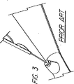
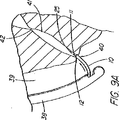
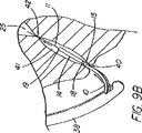
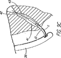
OTW技法によって装置の交換が可能になったが、ショートワイヤ技法の開発は、内視鏡でワイヤガイドの高い制御性が維持されるのを好む医師らに受け入れられた。この迅速交換技術の周知の例として、MICROVASIVE RX BILIARY STSTEM(商標)(マサチューセッツ州、ナトウィックのBoston Scientific Corporation)を備えている装置があるが、この装置では、装置のカテーテル部分は、装置にもよるが5cm乃至30cm離れた遠位側開口部と近位側開口部の間に伸張する内部ルーメンを含んでおり、従って、このシステム用に開発された長さ260cmのJAGWIRE(登録商標)ガイドワイヤに外挿して装置を取り外す際は、その長さ分の交換が求められる。このシステムの括約筋切開刀の例(AUTOTOME(商標)挿管括約筋切開刀)を図1に示している。ルーメンは、近位側開口部から近位方向に伸張して「C型チャネル」(図2に図示)を形成しており、カテーテル部分が内視鏡へと導入されると、このC型チャネルがワイヤガイドをカテーテル内に保持し、且つカテーテルが内視鏡から取り出されると、ワイヤを横方向にチャネルから引き抜いて、内視鏡の生検ポートにワイヤをアクセスさせ(図3)、第2のカテーテル型装置(例えば、バルーン、バスケット、ステント送出カテーテルなど)をワイヤの近位端に外挿して引き続いて送り込むことができるようになっている。第1装置の遠位部が内視鏡を出ると、医師がワイヤの制御性を得てアシスタントがアクセスを失う恐れ無く第1装置を引き抜くことができるようになるまで、ショート交換(医師とアシスタント間の同調した押し引き運動)が求められるが、これはOTW処理で使用されるものと実際には類似している。ワイヤガイドの近位端は、通常は、アクセスを失わないために処置の間大部分は内視鏡に固定されているが、カテーテルの交換や取り外しができるようにするために内視鏡から外されなければならない。 Although the OTW technique has allowed device replacement, the development of the short wire technique has been accepted by physicians who prefer to maintain high control of the wire guide in the endoscope. A well-known example of this rapid exchange technique is a device with a MICROVASIVE RX BILARY STST ™ (Boston Scientific Corporation, Natwick, Mass.), Where the catheter portion of the device also depends on the device Includes an internal lumen that extends between a distal opening and a proximal opening that are 5 cm to 30 cm apart, and thus the 260 cm long JAGWIIRE® guidewire developed for this system When removing the device by extrapolation, replacement for the length is required. An example of a sphincterotome of this system (AUTOTOME ™ intubated sphincterotome) is shown in FIG. The lumen extends proximally from the proximal opening to form a “C-shaped channel” (shown in FIG. 2), which when the catheter portion is introduced into the endoscope Holds the wire guide in the catheter and when the catheter is removed from the endoscope, the wire is withdrawn laterally from the channel, allowing the wire to access the biopsy port of the endoscope (FIG. 3), and the second Catheter type devices (eg, balloons, baskets, stent delivery catheters, etc.) can be extrapolated to the proximal end of the wire for subsequent delivery. When the distal portion of the first device exits the endoscope, the short replacement (doctor and assistant) until the physician gains control of the wire and the assistant can withdraw the first device without fear of losing access. (Synchronized push-pull movement between) is required, which is actually similar to that used in OTW processing. The proximal end of the wire guide is usually secured to the endoscope for the most part during the procedure to avoid losing access, but is removed from the endoscope to allow catheter replacement and removal. It must be.
Microvasiveシステムは、適度な時間節約と、医師によるワイヤのさらなる制御性を提供及び交換の実施を支援するアシスタントの技量への依存度の低減を提供しているが、ショート交換手技では、特にカテーテルを取り外す時にワイヤガイドを内視鏡に固定できないため、管へのワイヤガイドのアクセスが失われないよう注意を払わねばならない。ワイヤガイドがカテーテルのチャネル内にあり、連結された装置は付属チャネル内に一体に拘束されているため、カテーテルの遠位部が内視鏡の近位端を出るときには連結を解除しなければならない。この過程は、ワイヤとカテーテルの間の摩擦抵抗により更に時間がかかるため、この点が、次の交換処理で装置をカテーテルのルーメン又はC型チャネル内に在るワイヤに外挿して送り込み又は取り外す際に問題となる。 The Microvasive system offers modest time savings and provides more control of the wire by the physician and reduces the reliance on the assistant's skill to assist in performing the exchange, but for short exchange procedures, especially the catheter Care must be taken not to lose access to the tube because the wire guide cannot be secured to the endoscope during removal. Since the wire guide is in the channel of the catheter and the connected device is constrained integrally in the accessory channel, the connection must be released when the distal portion of the catheter exits the proximal end of the endoscope . This process is more time consuming due to the frictional resistance between the wire and the catheter, and this is the point when the device is extrapolated to the lumen in the catheter or the C-channel wire in the next exchange process to send or remove it. It becomes a problem.
カテーテルに沿ってC型チャネルを伸張させると、臨床学的欠点が生じ得る。例えば、カテーテルの割れ目は、ウィルスや細菌の周知の発生源である血液や胆汁がカテーテルのルーメンに入り込む進入箇所となり、入り込んだ血液や胆汁は、装置の近位端に移動し、そこで大抵は漏れ出て、床やこの処置に関わっている人々の衣服に付着する。チャネルは、潜在的に空気が漏れる箇所でもあり、これは処理の間に十二指腸内に適度な吹き込みを維持する能力を危うくしかねない。C型チャネルのもう1つの欠点は、カテーテルの品質を低下させることであるが、これは挿管装置(偏向型の括約筋切開刀など)で、管への進入経路を真っ直ぐにするために乳頭部を挿通させ又は「持ち上げ」ようとする場合に、或いは狭窄部を挿通させる場合に、問題となりうる。 Stretching the C channel along the catheter can cause clinical disadvantages. For example, a catheter breach is an entry point for blood and bile, which are well-known sources of viruses and bacteria, into the lumen of the catheter, where the blood or bile moves to the proximal end of the device, where it often leaks. Go out and adhere to the floor and clothing of people involved in this procedure. The channel is also a potential air leak point, which can jeopardize the ability to maintain a proper blow in the duodenum during processing. Another disadvantage of the C-type channel is that it reduces the quality of the catheter, which is an intubation device (such as a deflecting sphincterotome) that can be used to straighten the path of entry into the tube. This can be a problem when trying to insert or “lift”, or when inserting a stenosis.
現在の迅速交換又はショートワイヤシステムも、従来のOTW法に見られるいくつかの欠点を解決するに至っていない。例えば、複数のプラスチック製排液ステントを並べて配置する場合には、送出システムを取り外してワイヤを切り離さねばならないので、乳頭部の再挿管が必要になる。更に、既存の装置では、導管としても機能するカテーテルを第2ワイヤ用の空のルーメンを有する前に患者と施術部位から取り外さねばならないため、複数の管にステントを配置する場合など、第1ワイヤの次に第2ワイヤを配置する能力を提供していない。胆嚢装置を交換するための現在のシステムのもう1つの欠点は、2つのシステムの間に互換性がないことである。ロングワイヤ装置には、ショート交換ワイヤで使用する側部アクセスポートが無く、C型チャネルを備えたMICROVASIVE RX BILIARY SYSTEM(商標)装置はロングワイヤ交換には巧く作られておらず、C型チャネルが第1交換処理の間に破れると、近位側ワイヤガイドアクセスポート(開口チャネルを含む)を通してロングワイヤを導入し、それを導入時にチャネルから滑り出ないようにしておくことが困難である。また、C型チャネルは、同じ理由で、一般に、直径が小さいワイヤガイド(0.035インチ未満)には適合性が無い。システム同士に互換性が無いということは、医師が特定の患者にとって最良の装置と治療法を選択する場合に、全ての可能な選択肢を利用できるわけではないということを意味している。 Current rapid exchange or short wire systems have also not solved some of the disadvantages found in conventional OTW methods. For example, if a plurality of plastic drainage stents are placed side by side, the delivery system must be removed and the wire must be disconnected, necessitating re-intubation of the nipple. Furthermore, in existing devices, the catheter that also functions as a conduit must be removed from the patient and treatment site before having an empty lumen for the second wire, such as when placing a stent in multiple tubes. Does not provide the ability to place the second wire next. Another drawback of current systems for exchanging gallbladder devices is the incompatibility between the two systems. The long wire device does not have a side access port for use with a short exchange wire, and the MICROVASIVE RX BILARY SYSTEM (TM) device with a C-type channel is not well-made for long-wire exchange. Is broken during the first exchange process, it is difficult to introduce the long wire through the proximal wire guide access port (including the open channel) and keep it from slipping out of the channel upon introduction. Also, C-channels are generally not compatible with small diameter wire guides (less than 0.035 inches) for the same reasons. The incompatibility between systems means that not all possible options are available when a physician selects the best device and treatment for a particular patient.
必要とされているのは、ロングワイヤ交換法と互換性があり、上記欠点の解決を図った、施術部位内で効率的且つ信頼性のあるやり方で装置を交換するための改良されたショートワイヤシステム及び技法である。 What is needed is an improved short wire for exchanging devices in an efficient and reliable manner within a surgical site that is compatible with the long wire exchange method and addresses the above disadvantages. Systems and techniques.
複数の細長い医療用装置、例えばカテーテルなどの管状部材を、患者体内のワイヤガイドなどの体内に導入された誘導部材に外挿して、導入及び交換するための図示のシステム及び方法において、(ルーメン、管、器官、脈管、他の身体通路又は腔、或いはワイヤガイド/誘導部材のアクセスが、特定の処置又は一連の処置の間、維持される部位に至る経路、と定義される)施術部位内の誘導部材から第1装置(一次アクセス装置)を遠隔操作により連結解除し、これにより装置を取り外し易くし、且つ装置の交換が患者体外で行われること無く、二次アクセス装置を体内に導入されたワイヤに外挿して行う導入の単純化を図ることにより、医療用装置を導入及び交換するためのシステム及び方法によって、上記課題は解決され技術的な前進が達成される。本出願の主な着眼点は膵臓胆管系又は胃腸管内の何れかの部位内で装置を交換することにあるが、施術部位内で遠隔操作により装置を連結解除する本システム及び方法は、身体のどの部分に対しても体内に導入された誘導部材に外挿して装置を交換する任意適当な手技を適用できる。例を挙げると、限定するわけではないが、バルーン、ステント、グラフト、閉塞器、フィルタ、遠位側保護装置、切除、光線療法、密封小線源療法など用のカテーテル類、人工弁、又は他の、冠状動脈、周辺動脈系(例えば、頚動脈や腎動脈)又は静脈系(例えば、脚部の深部静脈)を含む血管系に挿入される器具又は装置を、導入及び配置する場合である。他の代表的な部位を挙げると、生殖−泌尿器系(例えば、膀胱、尿管、腎臓、卵管など)、及び気管支系がある。また、本システムと方法は、体腔内で、例えば、腹膜、胸膜腔、偽性嚢胞又は真性嚢胞構造内で、ニードル、トロカール、又はシースによる経皮的配置又は交換を介して、装置を交換する場合に使用することができる。 In the illustrated system and method for extrapolating, introducing and exchanging a plurality of elongated medical devices, e.g., tubular members, such as catheters, to guide members introduced into the body, such as wire guides within a patient body (lumens, Within the treatment site (defined as the path to which a tube, organ, vessel, other body passage or cavity, or wire guide / guide member access is maintained during a particular procedure or series of procedures) The first device (primary access device) is disconnected from the guide member by remote control, thereby making it easy to remove the device and replacing the device outside the patient's body so that the secondary access device can be introduced into the body. The above problem is solved by a system and method for introducing and exchanging medical devices by simplifying the introduction by extrapolating the wire to the outside. It is achieved. The main focus of this application is to replace the device in either the pancreatic bile duct system or the gastrointestinal tract, but the system and method for remotely disconnecting the device within the treatment site Any appropriate technique for exchanging the device by extrapolating to the guide member introduced into the body can be applied to any part. Examples include, but are not limited to, balloons, stents, grafts, occluders, filters, distal protection devices, catheters for ablation, phototherapy, brachytherapy, prosthetic valves, or others This is the case of introducing and placing an instrument or device that is inserted into the vascular system including the coronary artery, peripheral arterial system (eg, carotid artery or renal artery) or venous system (eg, deep veins of the leg). Other representative sites include the reproductive-urinary system (eg, bladder, ureter, kidney, fallopian tube, etc.), and bronchial system. The system and method also replaces the device within a body cavity, for example, within the peritoneum, pleural cavity, pseudocyst or true cyst structure, via percutaneous placement or replacement with a needle, trocar, or sheath. Can be used in case.
遠隔的に連結解除するための装置の基本システムは、誘導部材、代表的にはワイヤガイド、を備えている。なお、これより後、本明細書で使用する「ワイヤガイド」という用語は、総称的な意味において、上記機能を果たすように構成されたあらゆる装置(例えば、小径のカテーテル、レーザーファイバー、ひも、プラスチックビード、スタイレット、ニードルなど)であって、技術的に見て医療技術分野で一般的に用いられている用語としてのワイヤガイド(又は「ガイドワイヤ」)と見なされないような装置であっても、そのような装置を含むものと理解されたい。遠隔的に連結解除することにより、他のショートワイヤ法(例えば、迅速交換)に使用されるものよりも短い誘導部材/ワイヤガイドを使用できるようになり、従って以後、本明細書で記述する方法は、総称的には「超ショートワイヤ」技法、又は施術部位によっては「管内交換(IDE)」、「血管内交換(IVE)」などと呼ぶことにする。ワイヤガイドの長さを従来の迅速交換ワイヤガイドよりも短くできた理由は、患者体外では交換が行われないようにしたからである。事実、遠隔的連結解除により、装置はワイヤ上で取り外されるわけではないので、導入される装置よりも交換ワイヤガイドを短くすることができる。例えば、Microvasiveの「迅速交換」処置の場合、使用される装置によっては5cm乃至30cmの外部交換をその都度行わなければならず、通常使用されるワイヤガイドが260cmであるのに対して、胆嚢装置の本発明によるシステムのワイヤガイド(145cmチャネルの十二指腸鏡に使用)は、通常185cm(最小機能長約180cm)である。ワイヤは、短いほど、一人の施術者で操作し易く、床、患者のベッド、器具台、画像化装置などのような滅菌処理されていない面への接触防止にも役立つ。長さが185cmであれば、必要な場合には、殆どの外部交換も行うことができる。また、本システムと適合性を持たない装置を交換するための長いワイヤに対応するため、ワイヤの近位端に随意的な連結機構を設け、ワイヤガイド延長部を係合させてワイヤの長さを(例えば、260cm又は480cmに)伸ばし、従来型の交換方式を行うこともできる。 The basic system of the device for remotely disconnecting comprises a guide member, typically a wire guide. In addition, after that, the term “wire guide” used in the present specification is a generic meaning of any device configured to perform the above function (for example, a small-diameter catheter, laser fiber, string, plastic). Bead, stylet, needle, etc.) that is not technically regarded as a wire guide (or “guide wire”) as a term commonly used in the medical arts Should also be understood to include such devices. Remote disconnection allows the use of a shorter guide / wire guide than that used for other short wire methods (eg, quick change), and hence the method described hereinbelow. Are generically referred to as “ultra-short wire” techniques, or “intravascular replacement (IDE)”, “intravascular replacement (IVE)”, etc., depending on the treatment site. The reason why the length of the wire guide can be made shorter than that of the conventional quick exchange wire guide is that the exchange is not performed outside the patient's body. In fact, remote disconnection allows the replacement wire guide to be shorter than the device being introduced because the device is not removed on the wire. For example, in the case of a Microvasive “rapid exchange” procedure, an external exchange of 5 to 30 cm must be performed each time, depending on the device used, whereas the commonly used wire guide is 260 cm, whereas the gallbladder device The wire guide (used for a 145 cm channel duodenoscope) of the present invention is typically 185 cm (minimum functional length of about 180 cm). The shorter the wire, the easier it is for a single practitioner to operate, and it also helps prevent contact with non-sterile surfaces such as floors, patient beds, instrument tables, imaging devices, and the like. If the length is 185 cm, most external exchanges can be performed if necessary. Also, to accommodate long wires for exchanging devices that are not compatible with the system, an optional coupling mechanism is provided at the proximal end of the wire to engage the wire guide extension so that the length of the wire Can be extended (e.g., to 260 cm or 480 cm) to perform a conventional exchange scheme.
誘導部材/ワイヤガイドには、第1の細長い医療装置(一次アクセス装置)、代表的には管状部材又はカテーテル装置が連結されるが、これは、通路又はルーメン、あるいは外部チャネル、外側リング、又は他の界面域のような連結領域が遠位部周辺にあり、その連結領域は、ワイヤガイドの一部を受け入れるように構成され、施術部位内で作動中にはワイヤガイドと医療装置の両者が解放可能な連結対を構成することができるように、ワイヤガイドの一部を受け入れるようになっている。連結領域は、細長い医療装置の一部であってもよいし、そこに共に配置された別の要素(例えば、細長い係合部材)を中心として配置されてもよいが、この別の要素も本出願での使用に限っては細長い医療装置の構成部分と考える。別の細長い係合部材は、ワイヤガイドとカテーテル装置が、再配置又は連結解除されるまで、両者を解放可能に固定する一次的又は二次的な手段を提供しうる。細長い係合部材は、必ずというわけではないが管状部材の通路内に配置されているのが一般的であり、この係合部材にも連結領域を更に備えることができる。本システムと共に使用される一次アクセス装置は、ロングワイヤ適合型の装置が選択された場合はロングワイヤを導入するために本システムを容易に変換できるように、(開放式又は分裂式チャネルではなく)装置の近位(外部)部分まで伸張している閉鎖式又は自己密閉式通路を有しているのが望ましい。また、本発明の装置は、従来のショートワイヤ交換が望ましい場合又は(予期せぬ解剖学的制約により)遠隔連結解除が厄介な場合には、ワイヤ外挿式に戻すことが可能な構成となっている。 Connected to the guide member / wire guide is a first elongate medical device (primary access device), typically a tubular member or catheter device, which may be a passage or lumen, or an external channel, outer ring, or There is a connection area around the distal portion, such as another interface area, which is configured to receive a portion of the wire guide, while both the wire guide and the medical device are in operation within the treatment site. A portion of the wire guide is received so that a releasable connection pair can be constructed. The connecting region may be part of an elongate medical device or may be centered about another element (e.g., an elongate engagement member) disposed therewith, but this other element is also a book. For use in applications only, it is considered a component of an elongated medical device. Another elongate engagement member may provide a primary or secondary means for releasably securing the wire guide and catheter device until they are repositioned or disconnected. The elongate engagement member is typically, but not necessarily, disposed within the passage of the tubular member, and the engagement member can further include a connection region. The primary access device used with the system (not an open or split channel) so that the system can be easily converted to introduce a long wire if a long wire compatible device is selected. It is desirable to have a closed or self-sealing passage that extends to the proximal (external) portion of the device. In addition, the device of the present invention is configured to return to wire extrapolation when conventional short wire replacement is desired or remote disconnection is difficult (due to unexpected anatomical constraints). ing.
本発明の第1の態様では、本装置は、標識システム(例えば、放射線不透過性マーカー、外部マーキング、内視鏡マーキングなど)のような位置合わせ標識システムを、ワイヤガイド及び/又は第1の細長い医療装置を中心としてさらに備えており、ワイヤガイドの遠位端又は遠位部を、ワイヤが出ている側部アクセスポート又はアパーチャ(例えば、開孔)のような連結領域の近位端に対して配置する際に利用することができる。都合がいいことに、この位置合わせ標識システムは、2つの装置が施術部位内で連結又は連結解除される際の医師による制御を可能にし、連結解除の確認を補助する。このような確認ができなければ、連結解除がいつ生じたのか又は生じようとしているのかを知らないまま、医師が(例えば蛍光透視法誘導下で)カテーテルとワイヤガイドの連結解除を試みることが極めて困難になりうる。体内の箇所又は施術部位並びに送出される装置にもよるが、「目視せずに」装置を連結解除を試みることはワイヤガイドアクセスを失う原因になり、特にワイヤガイドが係合されたまま装置が早まって引き抜かれてしまうと、そのような事態になりかねない。また、連結解除が生じたことを確かめるのに必要な、装置とワイヤガイドの間の相対移動量は、表示を使用した場合よりも一般的にはるかに大きく、従って、ワイヤガイドが遠くまで引き出されすぎてアクセスを失ったり、又は施術部位内の連結解除を行うための空間が不十分となる危険が増大する。代表的な迅速交換装置では、交換処置が患者体外で行われることを想定しているので、必要な放射線用の又はその他適当な表示を備えて構成されていない。外部交換は、低速の処理であり、別のカテーテル又はワイヤガイドを既存の装置(従来の迅速交換では常にワイヤガイド又は誘導装置である)に外挿して施術部位に前進させる前に、第1のカテーテルの取り出しが指図される。 In a first aspect of the invention, the apparatus includes an alignment marker system, such as a marker system (eg, radiopaque marker, external marking, endoscopic marking, etc.), a wire guide and / or a first Centered on an elongated medical device, the distal end or distal portion of the wire guide is at the proximal end of a connection region such as a side access port or aperture (eg, an aperture) through which the wire exits. It is possible to use it when arranging it. Conveniently, this alignment marker system allows control by the physician when the two devices are connected or disconnected within the surgical site and assists in confirming the disconnection. Without such confirmation, it is highly likely that the physician will attempt to disconnect the catheter and wire guide (eg, under fluoroscopy guidance) without knowing when the disconnection has occurred or is about to occur. Can be difficult. Depending on the location of the body or treatment site and the device being delivered, attempting to disconnect the device “without sight” can cause loss of wire guide access, especially if the device remains engaged while the wire guide remains engaged. If it is pulled out prematurely, this can happen. Also, the relative amount of movement between the device and the wire guide that is necessary to ensure that the disconnection has occurred is generally much larger than when using the display, so the wire guide is pulled far away. There is an increased risk of losing access too much, or insufficient space for releasing the connection within the treatment site. Typical quick change devices are not configured with the necessary radiation or other suitable indications because the replacement procedure is intended to take place outside the patient. External exchange is a slow process in which the first catheter or wire guide is extrapolated to an existing device (which is always a wire guide or guide device in conventional rapid exchange) and advanced to the treatment site before the first Removal of the catheter is directed.
本標識システムの第1の一連の実施形態は、一次又は二次アクセス装置と誘導装置の間の整合及び係合状態を判定するために、適当な外部誘導システム(蛍光透視法、MRI、CTスキャン、X線、超音波など)の下で施術者が使用する1つ又はそれ以上の装置に設けられた、放射線撮影用又は超音波反射性マーキングを含んでいる。第1の実施例は、ワイヤガイド及び第1の細長い医療装置の遠位端に設けられた放射線不透過性又は高密度帯、マーキングなどを備えている。具体的には、ワイヤガイドの遠位先端部には、一般的には、第1の細長い医療装置の連結領域の長さを少なくとも備えている放射線不透過部分があり、この部分はイリジウム、プラチナ、又は他の適した材料を含む帯のような放射線不透過性のマーカーを有し、連結領域の近位端周辺(例えば側部アクセスポート又はそのすぐ遠位側の位置)に配置されており、これによって、施術者は、装置が施術部位内で連結解除又は分離されるカテーテルの地点にワイヤの遠位先端部がいつ接近しているか又はこの点をいつ出たかを知ることができる。また、他の放射線不透過性マーカーとして、カテーテルの遠位端などでの遠隔連結解除を支援するのに一般には使用されていない放射線不透過性マーカー、又はステント又はバルーンの配置に使用されている標識、を設けてもよい。 A first series of embodiments of the present signing system is suitable for determining the alignment and engagement between the primary or secondary access device and the guidance device by using an appropriate external guidance system (fluoroscopy, MRI, CT scan). Radiographic or ultrasonic reflective markings provided on one or more devices for use by the practitioner under (X-ray, ultrasound, etc.). The first embodiment includes a wire guide and a radiopaque or dense band, marking, etc. provided at the distal end of the first elongate medical device. In particular, the distal tip of the wire guide typically has a radiopaque portion comprising at least the length of the connecting region of the first elongate medical device, the portion being iridium, platinum Or a radiopaque marker, such as a band containing other suitable material, and located around the proximal end of the connection region (eg, at the side access port or just distal thereof) This allows the practitioner to know when the distal tip of the wire is approaching or exits the point of the catheter where the device is disconnected or disconnected within the treatment site. In addition, other radiopaque markers are used for placement of radiopaque markers or stents or balloons that are not commonly used to assist remote disconnection, such as at the distal end of a catheter. A sign may be provided.
システム表示の第2の一連の実施形態は、ワイヤガイドの近位部付近に配置された直接視認可能標識と、処置中にはこれが連結される管状部材と、を備えている。ある実施例では、ワイヤガイドは、目視確認できる整列点を備えており、この整列点は、1つのマーカー(例えば、色帯)あるいはワイヤガイド外側被覆の異なる色及び/又は模様の領域の間の遷移点であって、これが細長い医療装置の近位部の所定の第1マーキングと整列するとワイヤガイドと管状部材の遠位端が互いに整列していることが示される。カテーテルは、係合解除点を表す第2のマークを更に含んでおり、これがワイヤガイドの所定の整列マーキングと整列すると、2つの装置は連結又は係合を解除されつつあるか又は既に解除され、ワイヤガイドの遠位先端部が連結領域を出た状態にあることが示される。カテーテルの近位部上の第1(遠位側)及び第2(近位側)マーキングは、処置中も患者又は内視鏡の外に留まる領域にあり、連結領域の長さと同じ距離だけ離間して配置されているのが望ましい。連結領域が非常に短い場合(例えばリング)は、近位側標識を使用するのであれば、カテーテル上の1つのマークが係合解除を示すことが望ましい。 A second series of embodiments of the system representation comprises a directly visible indicator disposed near the proximal portion of the wire guide and a tubular member to which it is coupled during the procedure. In certain embodiments, the wire guide includes a visually identifiable alignment point, which is between one marker (eg, a color band) or a different color and / or pattern area of the wire guide outer coating. A transition point is shown that the wire guide and the distal end of the tubular member are aligned with each other when aligned with a predetermined first marking on the proximal portion of the elongated medical device. The catheter further includes a second mark representing a disengagement point, when this aligns with a predetermined alignment marking on the wire guide, the two devices are either being connected or disengaged or have already been disengaged, It is shown that the distal tip of the wire guide is out of the connection region. The first (distal) and second (proximal) markings on the proximal portion of the catheter are in a region that remains outside the patient or endoscope during the procedure and are separated by the same distance as the length of the connecting region. It is desirable to be arranged. If the connecting region is very short (eg, a ring), it is desirable that one mark on the catheter indicate disengagement if a proximal indicator is used.
標識システムの第3の一連の実施形態は、光ファイバ内視鏡又は映像内視鏡(例えば十二指腸鏡、胃鏡、気管支鏡、尿管鏡など)で視認可能に構成されたマーキングを含んでいる。膵臓胆嚢系にアクセスするように構成された装置では、標識は、ワイヤガイド及び細長い医療装置それぞれの中間部分内に設けられたマーキングを備えており、通常の処置中は内視鏡の視認レンズ又はビデオチップの遠位側且つオリフィス膨大部の近位側にあって、管内で連結解除が生じたことを確認するビデオモニター(又は観察ポート)を使って整列させることができる。装置は、遠隔連結解除処置中に有用な他の内視鏡標識を含んでいてもよい。例えば、胆嚢カテーテルは、乳頭部内に埋め込まれるとワイヤガイドアクセスを失う危険性無しに管内でIDEを安全に行えることを示す深度マーキングを、カテーテル先端部から所定の距離(例えば10cm)に備えていてもよい。また、ワイヤガイドの先端部が管から完全に引き出されて乳頭部の再挿管が必要になる危険があるか否かを医師に警告する目に見える合図として、遠位部の外観は目立たせてもよい(例えば黒色)。第2及び第3の標識システムは、外部画像化処理を必要としないため、医師は患者が蛍光透視に曝される時間を制限することができ好都合である。例えば、他の種類の標識のうち少なくとも1つを別の場所で整合の案内として使用しながら処置を行う際は、蛍光透視は、選択された重要な時だけ使用することができる。 A third series of embodiments of the marking system includes markings configured to be visible with a fiber optic endoscope or a video endoscope (eg, a duodenoscope, a gastroscope, a bronchoscope, a ureteroscope, etc.). In devices configured to access the pancreatic gallbladder system, the indicia comprises markings provided in the middle portion of each of the wire guide and the elongated medical device, and during normal procedures, the endoscope viewing lens or It can be aligned using a video monitor (or viewing port) that is distal to the video chip and proximal to the orifice bulge and confirms that disconnection has occurred in the tube. The device may include other endoscopic markers useful during remote disconnection procedures. For example, gallbladder catheters are provided with a depth marking at a predetermined distance (eg, 10 cm) from the catheter tip to indicate that IDE can be safely performed in the tube without the risk of losing wire guide access when implanted in the nipple. Also good. The distal portion of the wire guide should be conspicuous as a visual cue to warn the physician whether the tip of the wire guide is completely pulled out of the tube and there is a risk of re-intubation of the nipple. (For example, black). Advantageously, the second and third labeling systems do not require an external imaging process, allowing the physician to limit the time that the patient is exposed to fluoroscopy. For example, when performing a procedure while using at least one of the other types of signs as an alignment guide at another location, fluoroscopy can be used only at selected critical times.
ワイヤガイドと第1の細長い医療装置(及び次の装置)が係合しているか連結解除されているかを確認する視覚的表示を使用することに加え、本発明は、装置が互いに対して動く際に装置の間の抵抗が増す不連続のポイントにより、係合解除が生じた又は生じようとしているポイントを医師が「触れる」又は感じるようにする1つ又はそれ以上の隆起及び/又は窪みを、1つ又はそれ以上の装置又は内視鏡の付属チャネルポートに沿って含んでいる触覚システムのような、他の型式の整列表示システムを含んでいる。磁石も触覚システムの構成要素となり得る。整列表示器システムの他の実施形態としては、センサを基本としたシステムを含んでおり、システム内にセンサが配置されている。カテーテル又は内視鏡チャネル/ポートに沿って配置されたセンサが、システム(例えば、ワイヤガイド又はカテーテル)内の何処かの較正位置を検知して、信号又は合図(例えば、電気信号)を送信または提供し、装置が連結解除されたか又はされつつあることを施術者に警告する音声又は視覚による警報の形態で伝達される。整列システムは、整列用の1つのシステム又は手段を備えていてもよいし、または視覚による表示器と視覚以外による表示器の組み合わせを備えていてもよい。 In addition to using visual indications to confirm whether the wire guide and the first elongate medical device (and the next device) are engaged or disconnected, the present invention provides for the device as it moves relative to each other. One or more ridges and / or depressions that allow the physician to “touch” or feel the point at which disengagement occurs or is about to occur due to discontinuous points between the devices Other types of alignment display systems are included, such as one or more devices or haptic systems including along an accessory channel port of an endoscope. Magnets can also be a component of a haptic system. Other embodiments of the alignment indicator system include a sensor based system in which the sensor is located. Sensors placed along the catheter or endoscope channel / port sense any calibration position in the system (eg, wire guide or catheter) and send a signal or cue (eg, electrical signal) or Provided and communicated in the form of an audible or visual alert that alerts the practitioner that the device has been disconnected or is being connected. The alignment system may comprise one system or means for alignment, or may comprise a combination of visual and non-visual indicators.
本発明の第2の態様では、第1の細長い医療装置とワイヤガイドの両方が施術部位にある間に、第1の細長い医療装置をワイヤガイドから連結解除するための方法(即ち、基本的な超ショートワイヤ技法)が提供されている。2つの装置は、内視鏡、導入器シースのような標準的な導入方法と導入器部材を使用して、導入される医療装置の連結領域を通してワイヤガイドが係合された状態で、施術部位に導入される。膵臓胆嚢系に使用される或る実施形態では、連結領域は、カテーテルの遠位部、例えば遠位側6cmの部分に通路を備えており、ワイヤガイドは、当該箇所で側部アクセスポート(例えば、開孔)を通り、カテーテルの近位部の外側に沿ってワイヤガイドとカテーテルの両方が導入経路に沿って並んだ状態で共に伸張するように、出ており、この導入経路は、胆嚢の実施形態では十二指腸鏡のチャネルとなる。例えば、括約筋切開刀、ニードルナイフ、ERCPカテーテルなどのような4aワイヤガイド又は一次アクセス装置は、ダクト挿管のために最初に管に導入されることができ、次いで一次アクセス装置はワイヤに外挿して前進させられ、診断及び/又は治療などの第1の医療処置を行う。この間、ワイヤガイドは、ワイヤガイド入口ポート(生検ポート)付近に配置された係止装置、クリップ、他の手段を介して近位部を内視鏡に取り付けられることによって定位置に好適に固定され、こうして長手方向にその位置を固定されて施術部位へのアクセスの維持を支援する。第1の装置が目的の動作(造影剤の注入、括約筋の切除など)を済ませると、施術者は、装置を配置し直す間の視認的案内を提供しているX線、内視鏡、及び/又は近位側の表示システムなどを好適に使用して、係合解除ができる。1つの技法(ここでは「装置IDE」と称する)は、連結が解除されるまで、一次アクセス装置を静止ガイドワイヤに外挿して前進させる段階を含んでいる。第2の技法(ここでは、「ワイヤガイドIDE」と称する)は、連結解除が生じたことを整列表示が示すまで、一次アクセス装置を静止位置に保ったまま、ワイヤガイドを引き抜く段階を含んでいる。第3の技法は、装置IDEとワイヤガイドIDEの折衷型である。更に、放射線不透過性のワイヤガイド先端部分が、通路を出る際には特徴的な「ホイッピング(whipping)」動作が現れるのが普通であるが、これは、蛍光透視下で視認可能であり、この動作確認も連結解除の目に見える独特な標識となる。 In a second aspect of the invention, a method (i.e., a basic) for disconnecting a first elongate medical device from a wire guide while both the first elongate medical device and the wire guide are at the treatment site. An ultra-short wire technique) is provided. The two devices use a standard introducer method such as an endoscope, introducer sheath and introducer member, with the wire guide engaged through the connecting region of the introduced medical device, and the surgical site. To be introduced. In certain embodiments used for the pancreatic gallbladder system, the connecting region comprises a passage in the distal portion of the catheter, eg, the distal 6 cm portion, and the wire guide is connected to the side access port (eg, ), And along the outside of the proximal portion of the catheter, both the wire guide and the catheter extend so that they extend together in line along the introduction path. In the embodiment, it becomes a channel of a duodenoscope. For example, a 4a wire guide or primary access device such as a sphincter knife, needle knife, ERCP catheter, etc. can be first introduced into the tube for duct intubation, and then the primary access device is extrapolated to the wire. Advance and perform a first medical procedure such as diagnosis and / or therapy. During this time, the wire guide is suitably fixed in place by attaching the proximal portion to the endoscope via a locking device, clip, or other means located near the wire guide inlet port (biopsy port) Thus, the position is fixed in the longitudinal direction to assist in maintaining access to the treatment site. Once the first device has performed the desired action (contrast injection, sphincter resection, etc.), the practitioner provides an x-ray that provides visual guidance while repositioning the device, an endoscope, and The disengagement can be performed using a display system on the proximal side or the like. One technique (herein referred to as “device IDE”) involves extrapolating the primary access device over the stationary guidewire until the connection is released. A second technique (referred to herein as “wire guide IDE”) includes withdrawing the wire guide while keeping the primary access device in a stationary position until the alignment indication indicates that disconnection has occurred. Yes. The third technique is a compromise between the device IDE and the wire guide IDE. In addition, the radiopaque wire guide tip typically exhibits a characteristic “whipping” action as it exits the passage, which is visible under fluoroscopy, This operation check is also a unique sign that can be seen when the connection is released.
医師が、整列表示器システムの少なくとも1つの構成要素を使用して、ワイヤガイドの先端部が一次アクセス装置の連結領域から係合解除されたと判断すると、第1装置は、内視鏡付属チャネル(あるいは血管又は他の或る種の内視鏡以外の用途の場合は導入用シース)から引き戻すだけで簡単に取り外すことができる。ワイヤがチャネル又はルーメンの中に在る場合にはワイヤガイドとカテーテルの間に摩擦が存在するが、これがなくなることにより、取り外しが容易になる。先に述べたMICROVASIVE RX(商標)胆道系装置(例えば、AUTOTOME(商標)括約筋切開刀)の中には遠位部に側部ポートを設けているものもあるが、どの装置も、遠隔又は管内交換を臨床的に実用化する表示の組み合わせを、又は可能にする表示の組み合わせすら、欠いている。また、側部アクセスポートの近位側に開口チャネルが伸張している装置では、装置とワイヤガイドが共に内視鏡の付属チャネル内に或るときには、ワイヤガイドの近位部がチャネルを「捜し」、再度入ろうとする傾向があるので、表示の有無に関わらず、管内又は施術部位内で連結解除することはできない。このように、遠隔接続解除は、ワイヤをチャネルから解放可能に係合解除するための何らかの手段無しには不可能となる。 When the physician uses at least one component of the alignment indicator system to determine that the distal end of the wire guide has been disengaged from the connection area of the primary access device, the first device can receive the endoscope attached channel ( Alternatively, for applications other than blood vessels or some other type of endoscope, it can be removed simply by pulling back from the introducer sheath. Friction exists between the wire guide and the catheter when the wire is in the channel or lumen, but this is eliminated to facilitate removal. Some of the previously mentioned MICROVASIVE RX ™ biliary system devices (eg, AUTOTOME ™ sphincterotomy) have a side port at the distal portion, but any device can be remotely or intravascularly There is a lack of display combinations that make the exchange clinically practical, or even display combinations that allow it. Also, in a device with an open channel extending proximally of the side access port, the proximal portion of the wire guide “looks for the channel” when the device and the wire guide are both in the accessory channel of the endoscope. “Because there is a tendency to re-enter, it cannot be disconnected in the tube or in the treatment site, regardless of the presence or absence of the indication. Thus, remote disconnection is not possible without some means for releasably disengaging the wire from the channel.
カテーテルとワイヤガイドの連結が解除されると、ワイヤの近位端は、第3の細長い医療装置(例えば、二次アクセス装置又は第1のものと同じ第2の装置)に外挿して施術部位に前進させるのに使えるようになる。本方法の或る実施例では、体内に導入されたワイヤの近位端は、遠位開口部を通して送り込まれ、二次装置の側部アクセスポートから出て、施術部位に進められる。二次装置を使用して第2の医療処置が行われた後、別の処置のために別の二次装置が必要な場合は、第1の二次装置(三次医療装置)がワイヤガイド及び患者身体から取り出され、ワイヤガイドは、最初の2つの装置のときと同じやり方で四次装置のためのアクセスを提供するのに使えるようになる。 When the catheter and wire guide are uncoupled, the proximal end of the wire is extrapolated to a third elongate medical device (eg, a secondary access device or a second device that is the same as the first) and the treatment site Can be used to move forward. In one embodiment of the method, the proximal end of the wire introduced into the body is fed through the distal opening and out of the side access port of the secondary device and advanced to the treatment site. After the second medical procedure is performed using the secondary device, if another secondary device is required for another procedure, the first secondary device (tertiary medical device) is connected to the wire guide and Removed from the patient's body, the wire guide can be used to provide access for the quaternary device in the same manner as for the first two devices.
本方法の或る変形例では、二つに枝分かれしている管又は血管に挿管する処置などの場合、一次アクセス装置は、ワイヤガイドとの連結を解除した後も、第2のワイヤガイド用の導入経路又は導管として、施術部位の所定の位置に留置されてもよい。そのような処置の一例としては、別々の肝葉から排液する2本の管にステントを配置せねばならない場合がある。第2のワイヤガイドは、典型的にはハンドル部分付近にある、通路と連通している第1装置の近位側ワイヤガイドポートあるいはハブを通して導入されるのが一般的である。この技法では、通常、カテーテルのロングワイヤ交換を必要とする。第2の選択肢は、ワイヤの完全制御を維持できるように、管状部材の壁を通して形成された近位側側部アクセスポート(例えば、開孔)を通してワイヤを導入することである。この実施形態では、カテーテル壁は、近位側アクセスポートと側部アクセスポートの間で割けるように構成されているか、又はロング交換が不要になるようにワイヤガイドを装置の遠位方向に向けて剥き出しにすることができる開放型又は自己密閉式チャネルを含んでいる。通路から横方向にワイヤガイドを取り外すか又は剥き出しにするのは、カテーテルの壁に切り込み線を入れる又は構造的に弱くする、割くことのできる等方性のカテーテル壁材料(例えば、PTFE)を使用する、カテーテルの壁に沿って密封可能継ぎ目又は係止継ぎ目を組み込む、あるいは壁を薄くする又は十分な力が加えられるとワイヤガイドが壁を割ってそれ自体の出路を形成することができる材料を使用するなど、どの公知の手段を使って行ってもよい。或いは、取り付けられたスリーブのような連結領域を含んでいるワイヤガイドを使用して、既に体内に導入されている標準的なワイヤガイドに連結させてもよいし、又は両方のワイヤガイドを一体に連結して細長い管状部材の通路を通して前進させてもよい。 In one variation of the method, the primary access device may be used for the second wire guide after it has been disconnected from the wire guide, such as in a procedure for intubation into a bifurcated tube or blood vessel. As an introduction route or a conduit, it may be placed at a predetermined position of the treatment site. An example of such a procedure may be placing a stent in two tubes that drain from separate liver lobes. The second wire guide is typically introduced through the proximal wire guide port or hub of the first device in communication with the passage, typically near the handle portion. This technique usually requires long wire replacement of the catheter. The second option is to introduce the wire through a proximal side access port (eg, an aperture) formed through the wall of the tubular member so that full control of the wire can be maintained. In this embodiment, the catheter wall is configured to break between the proximal access port and the side access port, or the wire guide is directed distally of the device so that no long exchange is required. It contains open or self-sealing channels that can be exposed. To remove or expose the wire guide laterally from the passageway, use an isotropic catheter wall material (eg PTFE) that can be broken or structurally weakened into the catheter wall. A material that can incorporate a sealable seam or locking seam along the wall of the catheter, or that thin the wall or, if sufficient force is applied, the wire guide breaks the wall to form its own exit path Any known means such as use may be used. Alternatively, a wire guide that includes a connecting region such as an attached sleeve may be used to connect to a standard wire guide already introduced into the body, or both wire guides may be joined together. It may be coupled and advanced through the passage of the elongated tubular member.
上記手段の1つで通路へのアクセスを得た後、ワイヤガイドは、蛍光透視法など外部画像法の下で案内され、所望の場所に入る。随意的にではあるが、第1の装置が括約筋切開刀又はその他の種類の偏向性カテーテルの場合、施術者は、第2ワイヤガイドの先端部を管又は血管の反対側(又は横の)分枝内へと案内するのを支援するため、カテーテル先端部の形状と向きを操作することができる。施術部位内での方向決めは、回転可能ハンドルで先端部を方向決めすることにより容易になる。また、本発明に例示している185cmの胆嚢ワイヤガイドのような或る種の短いショートワイヤガイドであれば、施術者が指でワイヤを回すだけで、多くの場合に同様な成果を達成できるだけの回転力を伝えられることが実証されている。 After gaining access to the passageway with one of the above means, the wire guide is guided under external imaging methods such as fluoroscopy and enters the desired location. Optionally, if the first device is a sphincterotome or other type of deflectable catheter, the practitioner can place the tip of the second wire guide on the opposite (or lateral) side of the tube or vessel. To assist in guiding into the branch, the shape and orientation of the catheter tip can be manipulated. Orientation within the treatment site is facilitated by orienting the tip with a rotatable handle. Also, with some short short wire guides such as the 185 cm gallbladder wire guide illustrated in the present invention, a practitioner can often achieve similar results simply by turning the wire with his finger. It has been demonstrated that the rotational force of can be transmitted.
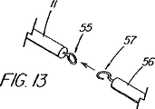
本発明の別の態様では、一次アクセス装置は、連結領域内又はその付近(例えば、管状部材の遠位側通路)でワイヤガイドに解放可能に係合するように作られている細長い係合部材を更に含んでいる。実施形態は、一杯に前進した位置にくると通路内でワイヤガイドを楔止めにするように作られている可撓性を有するワイヤストッパ(例えば、ナイロンスタイレット)、及びワイヤガイドを係蹄してこれを管状部材に対して長手方向に固定位置に維持する張力を与える糸状部材(例えば、縫合糸)を使用することを含んでいる。導入時に細長い係合部材が使用されない場合、例えば二次アクセス装置が、既に体内に導入されているワイヤガイドに外挿して導入される場合は、管状部材の通路に補強用スタイレットを随意的に維持して、導入中の装置の剛性を高め、及び/又は側部アクセスポートのような管状部材の開孔を横断させてねじれを防ぐ効果が発揮できるようにしてもよい。 In another aspect of the present invention, the primary access device is an elongate engagement member configured to releasably engage a wire guide within or near the coupling region (eg, a distal passage of the tubular member). Is further included. Embodiments include a flexible wire stopper (eg, a nylon stylet) that is configured to wedge the wire guide within the passageway when in a fully advanced position, and snare the wire guide. Using a thread-like member (e.g., a suture) that provides tension to maintain it in a fixed position longitudinally relative to the tubular member. If the elongate engagement member is not used at the time of introduction, for example when the secondary access device is introduced by extrapolation to a wire guide already introduced into the body, a reinforcing stylet is optionally provided in the passage of the tubular member. It may be maintained to increase the rigidity of the device being introduced and / or to traverse the opening of a tubular member, such as a side access port, to prevent twisting.
本発明の更に別の態様では、遠隔連結解除装置のシステム又は超ショートワイヤ技法は、プラスチック製の管状排液ステントの送出カテーテルと、1回の挿管処置を使用して胆管内に複数のステントを並べることを可能にする配置技法を含んでいる。ステントの遠位側の地点で側部アクセスポートを内側搬送部材(これに外挿してステントが取り付けられる)に配置することにより、ワイヤガイドを管内で連結解除し、処置中にワイヤを含めシステム全体を引き抜く必要無しにステントを配置することができるようになる。内側搬送部材とワイヤガイドの間の接合部は、内側部材が引き戻されるときにステントを「キャッチ」するのに好都合に使用され、こうしてステントを含め送出システム全体を管内で引き戻すことができるようになっている。この機構は、他の送出システムには無いものであるが、ステントを管の奥まで前進させすぎて配置直しが必要となる状況に対処するのに特に重要である。ステントが正しく配置されると、内側搬送部材は前進させられ及び/又はワイヤガイドが引き抜かれて2つの装置が連結を解除され、第2のステント送出カテーテル(及び追加ステント)が管内へと前進して第1ステントの横に沿って配置されるようにワイヤガイドを後に残したまま、内側搬送部材を、ステントを通しそして管から引き抜くことができるようになる。豚の尾型ステント、及び錨着用の成形された遠位部分を含んでいるその他ステントは、送出の間は連結領域を横断するワイヤガイドにより一時的にまっすぐにすることができる。 In yet another aspect of the present invention, the remote decoupler system or ultrashort wire technique uses a plastic tubular drainage stent delivery catheter and a single intubation procedure to place multiple stents in the bile duct. Includes placement techniques that allow them to be lined up. The entire system, including the wire during the procedure, disengages the wire guide by placing the side access port on the inner delivery member (to which the stent is attached by extrapolation) at a point distal to the stent. The stent can be placed without the need to pull out. The joint between the inner delivery member and the wire guide is advantageously used to “catch” the stent when the inner member is pulled back, thus allowing the entire delivery system, including the stent, to be pulled back in the tube. ing. While this mechanism is not present in other delivery systems, it is particularly important in dealing with situations where the stent is advanced too far into the tube and repositioning is required. When the stent is correctly positioned, the inner delivery member is advanced and / or the wire guide is withdrawn, the two devices are disconnected, and the second stent delivery catheter (and additional stent) is advanced into the tube. The inner delivery member can then be pulled through the stent and from the tube, leaving behind the wire guide to be placed alongside the first stent. Porcine tail stents, and other stents that include a molded distal portion to be worn, can be temporarily straightened by a wire guide that traverses the connecting region during delivery.
本発明の更に別の態様では、内視鏡のチャネル内にあって内視鏡の先端の周りでワイヤガイドを係合しているか、内視鏡に装着されて(または内視鏡と共在して)ワイヤガイドを沿わせて係合している、内視鏡及びガイドワイヤ搬送機構を使用して、ワイヤガイドを患者の口から通して下方に引く又は送ることによって配置することができる。胃食道(GE)接合部のような治療部位が可視化され、内視鏡の近位部分にある目盛標識を使って患者口部までの距離が測定される。ワイヤガイドは、ワイヤガイド搬送機構に連結されたままで、治療部位を越えて既知の距離(例えば、10cm)進められて胃の中に入り、そこで処置に続いて連結解除が行われる。ワイヤガイドは、GE接合部のような治療部位に対する既知の基準点(例えば、10cmの地点)に在る基準マークを含んでいる。ワイヤガイドの近位部は、異なる色の帯、あるいはGE接合部の基準マークまでの特定の距離を示す異なる数字又は型式のマーク(通常は非数字表示を使用)を有する間隔(例えば5cm)などの目盛り標識を含んでいるのが好ましい。ワイヤガイドを定位置に置いて、GE接合部のような所望の治療部位に一次アクセス装置を案内し配置するため、施術者は、拡張器、PDTバルーン、アカラシアバルーンなどの一次アクセス装置の近位部にある標識をワイヤガイド上の対応する標識と整合させながら、装置を前進させる。より大きい拡張器のような二次アクセス装置が必要な場合は、第1装置をワイヤに外挿して胃の中に前進させて連結を解除し、ワイヤに外挿して送られる次の装置がワイヤを利用できるようにする。内視鏡の外側でワイヤを搬送して空腸又は他の胃食道系部位も含みうる治療部位まで進めることによって、患者体内での内視鏡の操作性を確保するという利点を残しつつ、内視鏡の付属チャネルよりも大きな装置を配置するための手段が好適に提供される。 In yet another aspect of the present invention, the wire guide is engaged within the endoscope channel and around the distal end of the endoscope or attached to the endoscope (or coexisting with the endoscope). Using an endoscope and guide wire transport mechanism engaged along the wire guide, the wire guide can be placed by pulling or feeding it down through the patient's mouth. A treatment site, such as a gastroesophageal (GE) junction, is visualized and the distance to the patient's mouth is measured using tick marks on the proximal portion of the endoscope. The wire guide remains connected to the wire guide delivery mechanism and is advanced a known distance (eg, 10 cm) beyond the treatment site into the stomach where the connection is released following the procedure. The wire guide includes a fiducial mark at a known fiducial point (eg, a 10 cm point) for the treatment site, such as a GE junction. The proximal portion of the wire guide may be a different colored band or a spacing (eg, 5 cm) with different numbers or types of marks (usually using non-numerals) that indicate a specific distance to the fiducial mark at the GE junction. It is preferable that the scale mark is included. To place and guide the primary access device to the desired treatment site, such as a GE junction, with the wire guide in place, the practitioner is proximate to the primary access device, such as a dilator, PDT balloon, or achalasia balloon. The device is advanced while aligning the markings on the part with the corresponding markings on the wire guide. If a secondary access device, such as a larger dilator, is needed, the first device is extrapolated into the wire and advanced into the stomach to release the connection, and the next device that is extrapolated to the wire is sent to the wire. To be available. Endoscopes have the advantage of ensuring the operability of the endoscope within the patient by transporting the wire outside the endoscope and proceeding to a treatment site that can also include the jejunum or other gastroesophageal system sites Means are preferably provided for positioning the device larger than the accessory channel of the mirror.
以下、本発明の実施形態を、添付図面を参照しながら一例として説明する。 Embodiments of the present invention will be described below by way of example with reference to the accompanying drawings.
ロングワイヤ又は標準的ショートワイヤ交換手順を使用することなく、患者体内で第1の医療装置をワイヤガイドから遠隔的に連結解除することにより、一連の医療装置をワイヤガイドに外挿して患者体内に導入するための実例的なシステムと方法を図4から図57に示している。本システムの第1の代表的実施形態を図4及び図5に示しているが、このシステムは、図示の管状部材77又はGLO−TIP II(登録商標)E.R.C.P.カテーテル(ウィルソン−クック メディカル インク)に似た特徴を含んでいるカテーテルなどの第1の細長い医療装置10を備えており、このカテーテルは、第1の遠位端75(装置の遠位端に向いている)と、第2の近位端76と、標準直径の交換ワイヤガイド11(例えば、METRO(登録商標)ワイヤガイド;ウィルソン−クック メディカル インク)又は第1の細長い医療装置10と連結するのに適した他の案内装置を受け入れる寸法形状に作られた相互接続通路31とを有する連結領域14と、を更に含んでいる。連結領域14は、一般的には管状部材77(第1の細長い医療装置10)の遠位部13の辺りに位置しており、主要通路27の遠位部と(図示のように)一致していてもよいし、それとは別であってもよい。第1の細長い医療装置の遠位部13とワイヤガイドの遠位部60は、連結領域14を介して前者が後者に係合しているが、医療処置とそれに続く両装置の連結解除が行われる間、施術部位内に配置されている各部として、通常定義される。本開示では、施術部位は、孔、管、器官、血管、他の体内通路/体腔、又はそれらに至る経路であって、特定の医療処置/手術又は一連の処置を行うためにワイヤガイドアクセスが維持される場所、と定義される。例えば、胆管系に関わる処置では、施術部位は、膵管及び肝葉内へと伸張している管を含む総胆管とみなされる。
By remotely uncoupling the first medical device from the wire guide within the patient without using a long wire or standard short wire replacement procedure, the series of medical devices can be extrapolated to the wire guide and into the patient. Illustrative systems and methods for implementation are shown in FIGS. A first exemplary embodiment of the system is shown in FIGS. 4 and 5, which system is shown in the illustrated
連結領域は、第1の細長い医療装置10を、ワイヤガイドに外挿して連結された状態で施術部位に共に(順次又は一緒に)導入できる(例えば、ワイヤガイド11が第1装置10の通路27を通る)ように構成されており、ワイヤガイド11と管状部材が患者身体又は内視鏡を出るときには、ワイヤガイドの近位部59が通路を出て管状部材77の外に出るようになっている。これにより、医師は、従来型のショートワイヤ交換又は迅速交換と同様、ワイヤの制御がしやすくなる。図4及び図5に示す連結領域14の第1端75は、管状部材77内に遠位開口部19を備えており、第2端76は、管状部材77の側壁を横断し且つ管状部材の遠位端12から約6cmに位置している側部アクセスポート15又は開孔を備えている。図示の連結領域14は、主ワイヤガイド通路27の遠位部を備えている連結領域通路31とともに、第1の細長い医療装置10の遠位部13に配置されている。連結領域14の長さの範囲、即ち細長い部材10の側部アクセスポート15(又は第2端76)と遠位端12の間の距離は、連結解除点が、施術部位内で遠隔的に連結を解除できるだけ装置の遠位端に近ければ、装置及び用途に従って変えてもよい。6cmという距離は、連結解除に必要な相対的な運動のために、多くの事例において、十分な余地を確保する、といった管の解剖学的制約に適合する一方で、不慮の連結解除を防止する十分な長さを提供している点で、本発明の多くの胆道系装置にとって好都合な連結領域長である、と判断されている。
The connection region allows the first elongate
胆道系に適用する場合、連結領域長の範囲は1cm未満(例えばリング)から少なくとも15cmの間であってよい。殆どの装置にとって更に好適な長さの範囲は約3cmから10cmであり、最適範囲は約5cmから7cmである。膵管用の装置では、利用可能な距離が短めのときは、側部アクセスポート15から遠位端12までの理想的な距離は2cmから5cmである。更に空間が狭い体腔内での使用を意図した装置では、交換を成功裏に達成するため、装置の先端部12に極めて隣接させて又は正にその箇所に、側部アクセスポート15を配置する必要がある。他方、ある種の血管処置のようにワイヤガイドアクセスを失うことがそれほど問題ではない処置の場合、及び腸管のように長い通路で作業する場合には、側部アクセスポート15と連結領域14を設ける箇所に関しては更に多くの選択肢がある。
When applied to the biliary system, the range of the connecting region length may be between less than 1 cm (eg a ring) and at least 15 cm. A more preferred length range for most devices is about 3 cm to 10 cm, with an optimum range of about 5 cm to 7 cm. For devices for the pancreatic duct, when the available distance is short, the ideal distance from the
図示の側部アクセスポート15は、通常カテーテル幅の約1/4から1/3を有する半円形(断面図で、又は上から見た場合は卵形)の開口部を備えているが、ワイヤガイドの通路を通せる寸法または形状であればどの様な開口でもよい。少なくともワイヤガイド出口ポート(側部アクセスポート)の周辺領域内で、管状部材を横切る、そこに接着された、埋め込まれた、または補強する1本か数本のワイヤ、シース、バンド、ブレード、または別の手段によって、側部アクセスポート15の領域を補強して、その場所でのよじれを阻止することは、好都合となりうる。ワイヤガイド11は、第1装置10の遠位開口部19から近位方向に伸張し、通路31及び連結領域14を、側部アクセスポート15を通って近位方向に出ており、医師は、ワイヤの近位端にアクセスし、必要に応じて処置の間にこれを操作し、係止し、又は他のやり方で固定できるようになっている。上記のように、連結領域14の距離が比較的短いので、連結装置を互いに関連させて移動させて互いから係合解除または連結解除するのに好都合である。これは、カテーテル10を固定されたワイヤガイド11の遠位先端部25に向けて前進させるか、カテーテルからワイヤガイドが引き抜かれ側部アクセスポート15/連結領域14を抜け出るまでワイヤガイドを引き戻すか、あるいはカテーテルの前進とワイヤガイドの引き抜きを組み合わせることによっておこなわれ、そのいずれもワイヤガイドが施術部位(例えば管)内に留まって、体内にあるワイヤに外挿された次の装置のアクセスを容易にする、という様式において好ましい。
The illustrated
本発明では、外部交換が必要とされないため、ワイヤガイド11の長さを決めるには、遠位部60を(例えば、連結解除を行うため)施術部位へと前進させるための最遠点と、施術部位から患者又は内視鏡の外側まで伸張する中間部97と、ワイヤガイドを定位置に固定するなどの操作を施術者が行うのに十分な長さだけそこから伸長している近位部59(図7)と、を考慮に入れさえすればよい。図示の胆管に係る実施形態では、内視鏡の付属チャネルから最小限の且つ適正な伸張部を提供するために、ワイヤガイド11の長さを185cmとしているが、他の処置ではそれよりも短い又は長い長さが必要になる場合もありうる。ワイヤガイド11の長さは、操作、係止又は定位置に固定するのに十分な長さでありさえすればよいが、必要ならば、(遠隔係合解除が何らかの理由で不可能あるいは妥当ではない場合など)適切な形状の装置を用いなければならない場合は、近位部59の寸法は、好ましくは従来のショートワイヤ交換手法に適したものにするべきである。ワイヤガイド11の寸法は、連結領域において、摩擦を最小限にして摺動可能および解放可能であるのが好ましいが、特定の地点からカテーテル(またはワイヤと共に伸張している補助装置)がワイヤを解放可能に係合し固定するメカニズムは本発明の一部と考えられる。図5の連結領域14は、通路27の遠位部(通路31)を備えており、通路の近位部28は側部アクセスポート15地点から近位方向に伸張するルーメンの連続部となっている。代わりに、近位側通路28は、近位側通路へと連続させるのではなく、側部アクセスポート15のすぐ近位側を(可動フラップ、又はプラスチック又は金属のインサートなど永久的障害物で)少なくとも部分的に遮断又は制限して、遠位開口部19から装填されたワイヤガイドが側部アクセスポートから容易に出るのを助ける案内又は傾斜部として機能させてもよい。遮断手段(図示せず)は、流体又は他の物質が通路を逆流することを制限するのにも役立つことがある。関連する実施形態では、ワイヤガイド通路27は、近位方向には側部アクセスポート15までしか伸びておらず、その箇所で終わっている。
In the present invention, no external exchange is required, so to determine the length of the
図4と図5の図示の連結領域14は、膨大部オリフィスのような狭い狭窄部に挿管するのに使用される一次アクセス装置など、管状部材77の遠位開口部19から伸張するワイヤガイド11を有することが特に好都合な用途には好適な実施形態であるが、ワイヤガイドを、これと共に又はこれに外挿して導入される装置に一時的に連結できるようにする構造上の改造はどのようなものであれ、遠隔連結解除を目的とした連結領域14の実施形態を備えていると理解されたい。例えば、図6は、連結領域14が、管状部材通路27の一部ではなく、外部連結要素又はチャネル30を備えている本発明の別の実施形態を示している。図示の外部チャネル30には通路31が貫通形成されており、このチャネル30は、カテーテル本体と一体形成されるか、或いはカテーテル本体に接着又は他のやり方で取り付けられるかの何れでもよい。また、外部チャネル30は、管状部材77を取り巻く短いシース、プラスチック又は金属のリング、その他ワイヤガイドとの連結領域14を形成することのできる通路31を形成するどの様な構造を備えていてもよい。
The illustrated connecting
図30は、内部通路を有していない装置用の外部チャネル30の或る実施形態を示している。細長い医療装置10は、ワイヤ誘導式ワイヤ111を備えており、連結領域14は、ワイヤ111に接着されている収縮包装材料の外側スリーブ112と、連結領域14の第1及び第2端75、76の表示器17、18として作用し、第1スリーブ112に接着されている放射線不透過性材料からなる内側スリーブ113と、を有する外側チャネル30を備えている。標準的なワイヤガイド(0.021インチのMETRO(商標)ワイヤガイドなど)を連結領域を通して送り、2本のワイヤを、既に体内に導入されている管状部材を通して施術部位へ前進させるか、又はワイヤ誘導ワイヤ111を体内に留置されている標準ワイヤガイド(これも管状部材に連結されていてもよい)の近位端に外挿して送り、施術部位へ前進させるか、の何れかが行われ、施術部位で連結解除される。
FIG. 30 illustrates an embodiment of an
図14は、連結領域14が連結リング63を備えている別の実施形態を示しており、この連結リング63は、図示の実施形態では、胆石を捕獲するための実例的なワイヤ回収バスケット64(ウィルソン−クック メディカル インクのWEB(商標)抽出バスケットの変更型)のような回収装置64の遠位先端部74に取り付けられている。図示のリング63は、その中を通って第1装置10に係合するワイヤガイド11により良好に対応できるように、軸回転可能に作られているのが望ましい。連結リング63は、内部通路の係合を固定するものとして設けられているのではなく、(この特定の実施形態では、コイル状に巻かれたワイヤで作られた)細長い医療装置10のシャフト部内に適切な通路を欠いているある種の装置のためのオプションである。リング63は、連結を解除する際に必要な装置間の相対移動量が最小でよく、施術部位が短い場合又は他の解剖学的構造上の制約に直面した場合には有利である。
FIG. 14 shows another embodiment in which the
図31から図36は、連結領域14の、一連の代替実施形態を示している。図31は、連結領域14が別の要素に設けられている管状部材77を示しており、この別の要素は、図示の実施形態では、第2通路115内に滑動可能に配置されたシャフト部164を有する細長い係合部材89を備えており、管状部材77の遠位端12から伸張し、ワイヤガイド11を貫通させる第1及び第2開口部75、76を含んでいるカニューレ部115を介してワイヤガイド11と係合している。細長い係合部材89を第2通路115内に配置することにより、第1通路27は、物質を注入し、又は第2ワイヤを通すのに使える状態にある。図32の実施形態も、第2通路115に別の細長い係合部材89を含んでおり、この細長い係合部材89は更に連結領域14を備えている。この図示の実施形態では、細長い係合部材89は、側部アクセスポート15から伸張しており、ワイヤガイドを捕らえて装置を一体に連結する遠位側リング又はループ45を含んでいる。随意的に、連結解除後、ループ45を折りたたんで通路115を通して引き抜くようにすることもできる。
FIGS. 31 to 36 show a series of alternative embodiments of the connecting
図33は管状部材であって、連結領域14の第1端75が部材の遠位端12の近位側で終端し、第2端76が管状部材の遠位端13付近に位置する側部アクセスポート15を備えている管状部材を示している。ワイヤガイド11は、最も遠位側の側部アクセスポート(第1端75)から出るとワイヤガイド11の遠位端25が先端部12から或る角度に向かうように、連結領域14に送り込まれる。このような構成になっているので、医師は、管状部材77を回転させて、ワイヤガイド11の先端部25を、例えば、二股に分かれた管又は血管の特定の分枝48、49へと、目標の方向に容易に向けることができる。管状部材77の遠位端12は、閉じていてもよいし、又は先端部付近に、連結領域の第2の、即ち連結領域の第1端75の代わりとなる開口部を設けて、好ましい場合には、ワイヤガイド11が図5と同様の様式で連結されるようにしてもよい。
FIG. 33 is a tubular member wherein the
図34から図35bは、ワイヤガイド11が、連結状態では連結領域14に引っ掛けられるようになっている、本発明の実施形態を示している。図34の実施形態では、ワイヤガイド11は、図示の「牧羊杖」のようなかぎ状の遠位部116を含んでおり、その遠位端25と、隣接する遠位部60は、側部アクセスポート15を介して確実に係合を達成するのに必要なだけ通路27内にあって、管状部材77の連結領域14に係合している。ワイヤガイド11は、通路27内で通路27と適度な摩擦係合をする寸法であって、不用意に外れるのを防止できるのが好ましい。図35aと図35bに示す関連する実施形態では、ワイヤガイド11の遠位側フック部116は、近傍に放射線不透過性マーカー帯17を含んでいる管状部材77の遠位開口部19に挿入されるように作られている。図示の遠位フック部116は、螺旋形状117に熱設定させることができるニチノール又は他の超弾性材料を備えており、一旦連結領域14の通路31から係合解除されると、事前に設定された形状になるよう、自体に巻きついて戻り、閉じたループ端118を作る。このような構造になっているので、ワイヤガイド11に外挿して第2装置を戻す際、フック部分116に邪魔をされずにすむ。随意的に、管状部材77は、装置を一体化して施術部位へ前進させる間、連結されたワイヤガイド11を少なくとも部分的に内在させる、長手方向チャネルか、側部アクセスポート15から近位方向に伸張する凹部か、遠位開口部19を含んでいてもよい。
FIGS. 34 to 35b show an embodiment of the invention in which the
管状部材77をワイヤガイド11に連結する方法の別の実施形態を図36から図37に示しており、管状部材は、一対の同軸部材100、119を備えており、その各部材は、連結領域14の全長(遠位端12から側部アクセスポート15)に亘って伸張するスロット状の開口部又はチャネル120、121を含んでいて、互いに整列すると、ワイヤガイド11を開放通路31から横方向に外せるようになっており、整列していないときには内側119及び外側100のシース部材の一方によって閉鎖されている。内側及び外側部材100、119の近位部(図示せず)は、医師が連結を解除するのに、回転整列がいつ生じたのかを判定できるように近位側マーキング又は構造を含んでいるのが望ましい。代わりに、スロット120、121は、互いに重なると、又は他の何らかのやり方で整列すると、整列によってワイヤガイドと通路31の連結解除が可能になったことを放射線撮影的に表示する、長手方向に伸張する放射線不透過性の縞を含んでいてもよい。
Another embodiment of a method for connecting the
上記連結領域14の実施形態は、カテーテルとワイヤガイドを一体に連結して作業部位に誘導する場合に、当業者が選択することのできる多くのオプションを単に例示する目的で示したものであり、その選定は、処置及び使用される装置の性質に影響を受ける。他の選択される実施例としては、限定するわけではないが、ワイヤを捕捉するためカテーテルに沿って又はカテーテルを通して伸張する解放可能又は破断可能な縫合糸又はワイヤ、両装置に設けられ、互換性があり連結可能である面構造又は要素、一時的な又は剥離可能な結合剤又は接着剤、磁石、あるいは2つの医療装置を一時的に連結する他の手段などがある。
The embodiment of the
遠隔連結解除のために作られた装置は、臨床医が、所与の装置と、特定の処置のためにこの装置が一時的に連結されるワイヤガイド又は誘導部材との間における整列又は係合の現在の状態を判定することができるようにする、整列表示器システムを含んでいるのが好ましい。装置が施術部位内で蛍光透視による誘導を利用する処置において、戦略的に配置された放射線不透過性の表示は、装置の整列の判定及び連結が解除された確認の好都合な手段を提供する。本発明では、画像化可能マーカーが具体的に特定の種類のものである必要はない。例えば、放射線不透過性帯又は他のマーカーの代わりに超音波反射性マーカーを使用してもよい。また、マーカーの個数及び配置は重要ではない。本発明の整列表示器システムは、第1の細長い装置10とワイヤガイド11が、両装置の連結が施術部位内で解除されたことを表示するために、外部画像法、直接観察法(外部から又は内視鏡による)、触覚法、あるいは音声又は視認アラームセンサ(例えば、装置の近位端付近に置かれた表示灯が作動)を介して医師を案内する、所定の又は事前に調整された方法又は手段を含んでいる、任意適当なシステムを備えていてもよい。
A device made for remote disconnection allows a clinician to align or engage between a given device and a wire guide or guide member to which the device is temporarily connected for a particular procedure. Preferably, an alignment indicator system is included that allows the current state of the display to be determined. In procedures where the device utilizes fluoroscopic guidance within the surgical site, the strategically placed radiopaque indication provides a convenient means of determining device alignment and confirming that it has been disconnected. In the present invention, the imageable marker need not be of a particular type. For example, ultrasound reflective markers may be used in place of radiopaque bands or other markers. Also, the number and placement of markers is not important. The alignment indicator system of the present invention allows the first
ここで図4及び図5を参照すると、施術部位内で第1装置10とワイヤガイド11の連結を解除する手順は、第1装置10とワイヤガイド11それぞれの遠位部13、60付近に第1標識システム16を追加配置することにより、大幅に容易になる。この標識システムは、第1装置がワイヤガイドといつ連結し、ワイヤガイドが連結領域14をいつ通過して出たか、医師又は施術者を蛍光透視鏡下で視覚的に案内する、一連の放射線不透過マーカーを備えている。直接視認観察下で行える交換手順は比較的少ないので、遠位側標識16は、通常、一連の外部画像化可能帯、マーキング、あるいはイリジウム、プラチナ、タングステン、金、バリウム、タンタラムなどの放射線不透過性(高密度)材料を備えるその他の標識を含んでいる。標識は、通常は他の放射線不透過性標識またや構造と相対的に整列するに便利な、装置の望ましい箇所に、重ね置き、接着、又は内蔵される。図示の第1(又は遠位側)標識システム16は、第1の細長い医療装置10(管状部材77)とワイヤガイド11の双方に一連の放射線不透過性マーキングを備えており、管状部材の遠位端12(又は連結領域の第1端75)付近に設けられた随意的な遠位側画像化可能マーキング17、側部アクセスポート15の近傍かつ遠位側に設けられた近位側画像化可能マーキング18、及びワイヤガイド11の遠位端25又は遠位部60付近に設けられた遠位側画像化可能部26又はマーカーがこれに含まれる。図4に示す遠位側マーキング17は、カテーテルシャフトとの対比に十分な放射線不透過性を有する放射線不透過性インクを含んでおり、図示の実施形態では、カテーテルシャフトもまた、基材のポリマーに硫酸バリウム又は他の適当な材料を添加することにより放射線不透過性とされている。近位側画像化可能マーキング18は、側部アクセスポート15を含んでいる開孔の遠位端に隣接したカテーテル表面に糊付け又は他のやり方で取り付けられたイリジウム又はプラチナの帯を備えている。この帯は、管状部材に取り付けられたとき十分に対比できるほどの放射線不透過性を備え、管状部材もまた、放射線不透過性物質又は顔料を含んでいてもよい。図5では、管状部材77の遠位側放射線不透過性マーカー17は、連結領域(側部アクセスポート15)の近位端76の帯18と同様の帯を備えている。図示の遠位側放射線不透過性ワイヤガイド部26(図5)は、プラチナ、又はタングステンや金など別の放射線不透過性物質から成るコイルばねを備えている。放射線不透過性充填材又はインクの利用は、放射線不透過性ワイヤガイド先端部26を製作するための手段としても考えることができる。放射線不透過性マーカー18を連結領域14の第2端76付近に配置すると、好都合にも目標点を供給することになり、医師は、ワイヤガイドの放射線不透過性先端部26がその付近を通過し係合が解除されたかを知ることができる。図示の実施形態では、マーカー18は、通常、側部アクセスポートの近位側にこれと隣接して設けられるが、ワイヤガイドと整列させるのに有用な任意適当な位置に配置することができ、図6に示すようにポート付近又はポートと整列させて配置してもよい。代わりに、マーカー18は、側部アクセスポートに隣接する区域に制限されず、連結領域全長に亘って伸張する放射線不透過性の縞又はスリーブを備えていてもよい。そのような実施例の1つを図31に示しており、ここでは、図示の金属製連結用カニューレ114は、プラチナ又はイリジウムのような放射線不透過性に優れた物質を含んでいる。図14と図32の実施形態では、連結領域14は、連結リング63を備えており、このリングは、医師が、ワイヤガイドの放射線不透過性の遠位部26がいつリングを通過して係合が解除されたかを判断するための助けとなるように、より一層の放射線不透過性を有することが望ましい。
4 and 5, the procedure for releasing the connection between the
標識21の第2のシステム又は型を図4及び図8に示しているが、これは、装置の遠位部13が施術部位内にあるときに患者の体外にある第1装置10/管状部材77の近位部36に設けられている。通常の操作では、近位側標識21は、整列確認の一次又は二次手段として、処置の間は臨床医が直接視認することができる。図8の胆嚢の実施形態では、近位側標識21は、管状部材77の周囲に設けられた標識35を備えており、望ましくは管状部材77の色又は模様と対比を成す色又は模様であり、カテーテルの遠位先端部から測定して160cm(第1又は遠位端62)から166cmマーク(第2又は近位端61)まで伸張する、一連の印字された帯を含んでいる。第1端62(160cm)は、ワイヤガイド上に位置する対応する近位側整列マーク37との整列点を表しており、2つの装置10、11の間の相対的位置を変えればすぐに連結が解除されることを示す、整列点81を備えている。ワイヤガイドの近位側整列マーク37を第2端マーク61に向けて位置を変えると、2つの装置は連結解除が生じる脱離点82に到達し、色帯は、更に位置を変えると連結解除が迫ることを警告する役目を果たしている。図4の実施形態では、近位側標識21は、160cmから166cmまで伸張する対比配色の連続した帯を備えている。既に述べたように、近位側標識の位置は特に重要ではないが、通常の処置中に施術者が視認できる状態に留まるように構成されているのが望ましい。帯35は、脱離点82までの相対接近度を表示する色の段階的移行(例えば、黄色からオレンジそして赤)を含んでいてもよい。図示の実施形態では、標識帯35の近位端の166cmマークは、第2ワイヤガイドの通路27への入り口地点を備えている、随意的な近位側部アクセスポート20の遠位端付近にあるが、この技法については以下に説明する。血管、肺、泌尿器などの処置等、胆道系以外で使用する場合には、近位側標識21は、カテーテルの遠位先端部から異なる長さの位置、即ち施術部位にアクセスするのに要する距離に関連する適切な位置に設けられることが多い。第1装置標識35の長さ(6cm)は、連結領域14(図5に図示)の長さに対応しているのが望ましい。
A second system or type of
先に指摘したように、近位側標識システム21の標識35における長さ160cmから166cmの領域は、処置中に臨床医が視認できるように、ほぼ常時、患者及び内視鏡付属チャネルの外に出る管状部材77上の位置に好都合に設けられている。図示の実施形態では、ワイヤガイドの第2整列点37は、図示のワイヤガイドの遠位部160cmが近位部25cmと外観上区別でき異なるように、METRO(登録商標)ワイヤガイド(ウィルソン−クック メディカル インク)の螺旋縞の特徴を含んでいる遠位部60と、遠位部60及び/又は中間部97とは視認的に対比される異なる色及び/又は模様の収縮包装又はコーティングなどの無地配色を備えている近位部59との間の色の変化により示される。代わりに、対比色又はインク或いは適した材料を、ワイヤガイド11の外表面に適用してもよいし、第1装置10の点61との整列により生じる脱離点82を確立する、遠位部60と近位部59の間の接合部37の付近の適当な場所に1つの帯を貼り付けてもよい。第2整列点37は、近位側標識21の遠位端62と整列すると、ワイヤガイドの遠位端25が第1装置10/管状部材77の遠位端12と整列するように、ワイヤガイド11上に設けられる。代わりに、ワイヤガイドは、単一の狭いマーキングを第2の整列点37に含んでいてもよいし、例えば近位側標識21の近位端及び遠位端61、62の両方に対応する複数のマーキングを含んでいてもよい。ワイヤガイド11及びカテーテル10の近位側標識21は、収縮包装、インク、帯、表面エッチング又は他の処理など、視認表示器を提供するのに適する任意の手段を備える。
As pointed out above, the 160 cm to 166 cm long region in the
整列の第3番目の種類83を図26aと図26bに示す。本図では、第1及び第2の内視鏡整列表示器84、85が、第1の細長い医療装置10(又は第2カテーテルなど)及びワイヤガイド11それぞれの中間部分にあり、それらの遠位部を施術部位41内で前進させると、第1及び第2表示器84、85が、通常、ファーター乳頭40と付属チャネルの遠位端87の間の視認可能区域86内にあるように、設けられている。これにより、管41(胆管系)内で連結解除がいつ生じたかを判定するために、施術者が双方の相対整列を監視することができるようになる。図示の実施例では、ワイヤガイドと第1カテーテル部材(図示せず)の各遠位端は、共に、ファーター乳頭40を横断して胆管41に入っている。第1の細長い医療装置10の上に、装置が管41へと導入される際に視認できる随意的な10cmマーキング29(図4に一対のプリント帯として図示)を、設けてもよい。10cmマーク29は、第1装置10が、管の中へと最小限の「安全」な又は十分な距離だけ前進したことを表示するための指針として使用することができ、図26a及び図26bに示すように、この10cmマーク29が視界から消えてしまうと上記状態となったことが示される。この時点では、内視鏡整列表示器84、85は、普通は、視認可能区域86内にある。図26aでは、カテーテルの第1内視鏡整列表示器84は、対応する第2内視鏡(ワイヤガイド)表示器85の近位側にあって、ワイヤガイド11が第1装置10に完全に連結されていること(即ち、連結領域を完全に横断していること)を示している。図示の方法では、施術者は、中間表示システム83を利用して、図26bに示すように、第1装置10を静止したワイヤガイド11(通常は、管内でのアクセスを維持するため動かないように係止又は固定されている)に対して前進させることにより、装置10の連結解除がいつ生じたかを判定する。2つの表示器84、85が整列すると、ワイヤガイドの遠位端は連結領域又は側部アクセスポートの近位端を出て、連結解除又は係合解除が行われる。連結解除中に管からワイヤガイドアクセスが失われないようにするための更なる内視鏡表示器として、ワイヤガイド11の遠位部60(例えば、遠位側6cm)に黒色のような異なる配色を用いて、中間部97(図7に図示)と対比させてもよい。ワイヤガイドの黒色部分が乳頭から現れるのを医師が見ると、再挿管しなければならない危険性をできる限り小さくするために、ワイヤは管の中へと戻し進められることになる。まだ連結が解除されていないが、ワイヤガイドの黒色部60が内視鏡で確認できる場合には、アクセスを失う危険性を犯さずに連結解除が安全に生じるようにするため、ワイヤガイド11と管状部材77を共に管の中へと更に前進させる。
A
非視認整列システムの実施例を図40に示す。本図では、ワイヤガイド11は、連結領域14の第2端75、例えば側部アクセスポート15を通過すると、施術者が両者の間の接触を感じ又は知覚して、更に位置を変えると連結解除が迫っていることが示されるように、図示の珠(ビーズ)のような表面の不連続部160を含んでいる。図示の側部アクセスポート15は、ワイヤガイド11を自由に通過させるがビーズ160が通過するときに一時的に抵抗が生じる大きさに作られた開口部159を含んでいる、可撓性を有するスカート部158を備えて構成されている。更に、スカート部158は、胆汁、血液、及び空気が管状部材の通路に漏れ出るのを防ぐのに役立つシールとして好都合に機能する。この他の考えられる表面の不連続部としては、側部アクセスポート15又は連結領域14と共に適切に構成された畝、隆起、歯、窪み、又は粗くされた部分が含まれ、施術者に触覚的なフィードバックを提供し、それによって2つの装置の間の整列及び係合の状態に対する指針を提供する。
An example of a non-visual alignment system is shown in FIG. In this figure, when the
胆管系内で医療処置を行うために使用される内視鏡装置は、通常はオッディ括約筋に挿管し管にアクセスする処置に使用される初期装置を含む「一次アクセス装置」と呼ばれるものと、施術部位内で1つ又は複数の処置を行うために一次アクセス装置と交換される「二次アクセス装置」と、に分けられるのが一般的である。本発明の一次アクセス装置の例には、管への開口部を拡大するために括約筋を切除するための括約筋切除刀(図10及び図11に図示)、括約筋の切除にも使用される針尖刀(図示せず)、及び放射線造影画像化のために管に造影媒体を注入するようになっているERCPカテーテル(図4及び図5)が含まれる。括約筋切除刀と針尖刀は、造影剤及び他の薬剤の注入のように、2つ又は多数の機能又は動作を行うように作られてもよい。括約筋切除刀の中には、管を掃引して中に詰まった結石又は石を取り除くために使用されるバルーンを含んでいるものもある。また、一次アクセス装置と二次アクセス装置を兼ねたものとして使用される、抽出バルーンのような装置もある。膵臓胆嚢処置では、一次アクセス装置は二次アクセス装置を交換されるが、この二次アクセス装置は、代表的には、結石の摘出又は破砕、組織標本採取、治療用放射線又は光線の送出、狭窄部(腫瘍など)の拡張又はステント留置、又は排液用のステント留置のような、治療機能を果たすように作られている。二次アクセス装置が特定の処置で使用される最後の装置である場合、遠隔連結解除に適合させる必要はないが、少なくとも1つの遠位連結領域を備えていて、延長器を追加する必要無しに装置をショートワイヤに外挿して前進させられるようになっているのが望ましい。一般的にいえば、ワイヤに外挿して胆管系へと普通に導入されるどの様な二次的アクセス装置(抽出、拡張、撮影用バルーン、拡張器、鉗子、ブラシ、ステント送出カテーテル、近接照射療法カテーテル、砕石器、バスケット、スネアなど)でも、装置の遠位部内に適した連結領域と、必ずしもというわけではないが望ましくは、装置の連結解除及び相対整列を積極的に確認できるようにするための上記3種類の標識システムの少なくとも1つと、を追加することにより、遠隔連結解除に実質的に適合させることができる。 Endoscopic devices used to perform medical procedures within the bile duct system are commonly referred to as “primary access devices”, including the initial devices used for procedures that are intubated into the odddy sphincter and access the tube. Generally, it is divided into “secondary access devices” that are exchanged with primary access devices to perform one or more procedures within the site. Examples of the primary access device of the present invention include a sphincter resection knife (shown in FIGS. 10 and 11) for resecting the sphincter in order to enlarge the opening to the tube, and a needle knives used for resection of the sphincter (Not shown) and an ERCP catheter (FIGS. 4 and 5) adapted to inject contrast media into the tube for radiographic imaging. The sphincter blade and the needle blade may be made to perform two or many functions or operations, such as injection of contrast agents and other agents. Some sphincters include a balloon that is used to sweep the tube to remove clogged stones or stones. There are also devices such as extraction balloons that are used as both primary and secondary access devices. In a pancreatic gallbladder procedure, the primary access device is replaced with a secondary access device, which typically includes removal or crushing of a stone, tissue sampling, delivery of therapeutic radiation or light, stenosis. It is designed to perform a therapeutic function, such as expanding or stenting a part (such as a tumor) or placing a stent for drainage. If the secondary access device is the last device to be used in a particular procedure, it need not be adapted for remote disconnection, but has at least one distal connection region without the need to add an extender It is desirable to allow the device to be advanced over a short wire. Generally speaking, any secondary access device (extraction, dilation, photographic balloon, dilator, forceps, brush, stent delivery catheter, brachytherapy, etc. that is normally introduced into the bile duct system by extrapolating to the wire Therapy catheters, lithotriptors, baskets, snares, etc.) also allow for positive confirmation of the appropriate connection area within the distal portion of the device and, but not necessarily, the disconnection and relative alignment of the device. By adding at least one of the above three types of marking systems, it can be substantially adapted for remote disconnection.
施術部位41にアクセスして医療処置を行うために、本発明の、一次アクセス装置(第1の細長い医療装置10)、ワイヤガイド11、及び二次アクセス装置(第3の細長い医療装置44)を使用する代表的な方法を図9aから図9fに示している。図示の方法の最初の段階は、診断及び治療処置を行うために胆管41にアクセスするための標準的な内視鏡技法を含んでいる。図9aは、ファーター乳頭40及びオッディ括約筋を視認するために口腔を介して十二指腸39に挿入された十二指腸鏡38を示しており、この十二指腸鏡38は総胆管41と膵管の開口部に置かれている。この代表的な方法では、拡張器カテーテル88とワイヤガイド11は、内視鏡の付属チャネル38から前進して、施術部位41(管)内で狭窄部に挿管される。一般的に医師らは、この処置段階で、ワイヤガイド11は挿管を支援するため一次アクセス装置10の先端部を通り越して前進しているか、又はワイヤガイドの遠位端25が通路27内にあるか、を判定するのを好む。図9bに示すように、拡張器カテーテル10(又は他の二次的アクセス装置)は、ワイヤガイド11に外挿して前進し、ワイヤガイドの近位部が側部アクセスポート15を出てカテーテルに沿ってチャネルを通って伸張するので、図12に示すように、両方が別々に内視鏡の付属チャネルを出る。内視鏡のチャネルの大きさが制限されている用途、又は両方の装置を並べて収容する余地が限られている他の用途では、全体の直径を大きくすること無くワイヤガイドを並べて置けるようにカテーテルに変更を加えてもよい。これは、開放型のチャネル(望ましくはワイヤを捕捉しえないもの)を形成することにより、又はカテーテル(図示せず)の長さに沿って平坦な長手方向部分を作ることにより実現することができる。
In order to access the
これも図12に示すように、ワイヤガイド11の近位部59は、必ずしもというわけではないが、通常はその遠位端25が施術部位41内の望ましい位置まで前進したところで定位置に固定される。図示のワイヤガイドホルダ50は、内視鏡のどこか他の位置に固定されるのではなく、付属チャネルへのアクセスポート51の開口部52に一部挿入又は被せられて、シールを提供するように構成されている点で、先行技術の装置に比べて改善されたものとなっている。ホルダ50は、輪縁、スリット付の膜(例えば、ポリスチレン、シリコーン、又は別の弾性ポリマー材)、小さい中央ルーメンを備えた発泡シール(例えば、シリコーン、ポリウレタンなど)、又はカテーテルとワイヤガイドの周囲を密封して近位方向に移動する流体がチャネルから出るのを防ぐ能力を有する他の設計を含め、1つ又はそれ以上の型式のシールを有する随意的な一体形成されたシール要素を更に含んでいる。ワイヤガイド11は、図示のように交互に上下させるやり方を使って、図示の曲がった「背骨」のような、装置の係止部66の一方側に沿って、間隔を空けて設けられた要素の間の第1の一連の空間53(又はチャネル、溝、スロットなど)に通してワイヤガイドを絡ませることにより定位置に固定される。図示のホルダは、3つのスロット53又は空間を係止部分66の第1の側に含んでおり、第2の一連の3つのスロット54又は空間を、処置のために第2のワイヤが必要になった場合に対応するため、係止部分66の反対側に含んでいる。
As also shown in FIG. 12, the
ワイヤガイドの近位部が医師から離れたところにある他のワイヤガイド交換手法とは異なり、図示の遠隔連結解除又は超ショートワイヤ技法に通常使用されるショートワイヤは、普通は結果的にワイヤガイドの近位端が医師の作業区域内に在ることになるので、二次装置を施術部位へ導入する際に、近位端へ容易にアクセスすることができる。図示のホルダは、ワイヤガイドの近位端部を下向きに向けて医師の邪魔にならないように作られているが、別の装置をワイヤに外挿して送る際、近位端が固定を解かれているときは、元の形に戻って内視鏡のアクセスポートの周囲の作業区域に入り込み、処置中の医師の邪魔になりかねない。この問題を緩和するため、図7には、ワイヤガイド11の近位端部59をワイヤの遠位部及び中間部に対してある角度79に向け、近位端58/近位端部分59が、通常は下に向き、且つ(そのように回転させた場合は)施術者から離れる向きになり、従って、内視鏡のアクセスポートの周囲の作業区域から外れた位置に配置され、一方では、次の装置を前進させるために医師が近位端にアクセスできるようにもなっている、ワイヤガイド11を示している。図示の実施形態は、185cmニチノール芯ワイヤガイド11を備えており、第3の細長い医療装置をそれに外挿して前進させるように、その約40cmから45cmは内視鏡から外に出て近位方向に伸張しているのが一般的であり、このワイヤガイドでは、曲がり部80即ち撓む位置は、近位端から約20cm乃至30cmに設けられているのが望ましいが、有用な範囲は0cmから50cmの間であれば何処でもよい。撓みの有用角度79は、医師の好み、内視鏡とワイヤガイドホルダの構成、及び他の要因により変わるが、内視鏡処置では約30度から約120度が一般的で、図示の実施形態では45度から90度の範囲がより好適である。曲がり部80をニチノールワイヤガイド11に作り出すには、材料を熱硬化させるか、又は機械的に過剰な応力を加え(冷間加工)て、望ましい撓み角度79と望ましい曲がり部80の半径(例えば、小さく比較的鋭利な曲がり部、又は大きくてより緩やかなもしくは丸い曲がり部)を実現する。
Unlike other wire guide replacement techniques where the proximal portion of the wire guide is remote from the physician, the short wire normally used in the illustrated remote disconnect or ultrashort wire technique typically results in a wire guide. Because the proximal end of the device will be within the physician's work area, the proximal end can be easily accessed when the secondary device is introduced to the treatment site. The holder shown is made so that the proximal end of the wire guide is pointed down and out of the way of the physician, but when the extra device is sent over the wire, the proximal end is unlocked. When it is, it may return to its original shape and enter the work area around the endoscope access port, which may interfere with the treating physician. To alleviate this problem, FIG. 7 shows that the
次に、図9cに示すように、ワイヤガイドが施術部位内の望ましい位置まで前進してしまうと、カテーテルは、ワイヤガイド上を、目的の作業を実行するための位置へと進められ又は引き戻される。図示の方法では、この作業には、障害物、つまりこの具体例では狭窄部を視認できるようにするため管41に造影用媒体43を注入することが含まれる。管内の考えられる障害物の診断に対するこの他の一般的に行われている方法は、最初に括約筋切除刀32(図10)を導入して造影用媒体43を注入するやり方である。結石のような障害物が発見された場合は、括約筋を切除して、結石を管から抽出するためにバスケット又はバルーンのような第2の装置を元のワイヤガイドに外挿して導入する。使用できる処置は他にも各種あるので、使用する装置の性質と順序は、本発明にとっては重要ではない旨理解されたい。
Next, as shown in FIG. 9c, once the wire guide has been advanced to the desired position within the surgical site, the catheter is advanced or retracted over the wire guide to a position for performing the intended operation. . In the illustrated method, this operation includes injecting a contrast medium 43 into the
最初の作業が終了すると、第1の細長い装置10が管41から取り出される。図9dに示すように、施術者は、ERCPカテーテルとワイヤガイド12、25の遠位端同士を、カテーテルを前進させる(図示)ことによって向かい合わせに配置し直すことにより、装置IDEを行ってもよいし、又は、ワイヤガイド11をワイヤガイドホルダから係止解除し、遠位端25がカテーテルから係合解除されるまで引き戻すことによりワイヤガイドIDEを行うこともできる。代わりに、臨床医は、装置とワイヤガイド10、11を、ワイヤガイド11が連結領域を出るまで両装置を同時に動かすことにより、係合解除又は連結解除することができるが、一般的には、それらを施術部位41内に保ったまま連結解除が行われる。先に論じたように、カテーテル10の遠位部13及びワイヤガイド11の遠位端25上の画像化可能表示18、26は、それぞれ、図9eに示すように係合解除又は連結が解除されたことを蛍光透視法下で確認するために利用される。連結解除が施術部位内で起きたことを確認するために、図4及び図8に示す近位側標識21及び/又は中間部表示83(図26a及び図26b)も利用される。この随意の段階を図12に示しているが、ここで、ワイヤガイド11は、内視鏡の生検ポートの開口部52の周りに(ポートの縁を覆って及び/又は中に挿入されて)取り付けられた例示のワイヤガイドホルダ50内の係止位置161にあり、次いで係合解除され、2つの装置10、11の近位側標識21が整列できるように一次アクセス装置10に隣接する係止解除位置162に配置される。ワイヤガイド11の近位側マーク37が一次アクセス装置10の整列マーク81の遠位側に留まっている限り、施術者には、ワイヤガイドの遠位先端部が管(図示せず)内でカテーテルの遠位端からまだ突き出ていることが分かる。2つのマーク37、81が整列状態になるように、ワイヤガイド11を引く(又は一次装置10が前進する)と、施術者は、2つの装置10、11の遠位端12、25が管内でほぼ整列したことを知る。施術者が引き続きワイヤガイド11を引く又はカテーテル10を前進させると、整列マーク37は係合解除マーク82と整列するが、これは、図示の実施形態では、ワイヤガイドの遠位端が通路又は連結領域から完全に引き出され、2つの装置が管内で連結解除されたことを示す。
When the first operation is completed, the first
連結解除が行われると、装置10、11の何れかが第3の細長い医療装置を施術部位に導入するための導管として利用できるようになる。図示の例示的な方法では、第3の細長い装置44は、ワイヤガイド11の後端58(図示せず)を拡張器カテーテル88の遠位開口部19に送り込んで側部アクセスポート15から出し、拡張器カテーテル88をワイヤに外挿して内視鏡の付属チャネル内に、次いで管41の中へ前進させることにより、ワイヤガイド11に外挿して導入される拡張器カテーテル88(図9f)を備えている。通常、施術者は、第3装置44を導入する前に、もう必要なければ、第1装置10を取り出すことを選択する。これは、ワイヤガイドを(例えば、図12のワイヤガイドホルダ50内に係止させるなど)定位置に維持しつつ、施術者が1つの連続動作でカテーテルを管及び内視鏡のチャネルの外に引き出すことで簡単に行なわれる。第1装置10が取り出され、第3装置44が施術部位に進められると、第2医療作業(例えば、狭窄部の拡張)が行われる。別の作業が必要な場合は、第3のカテーテル型装置(第4の細長い医療装置)を元のワイヤガイド11に外挿して前進させ、以下は同様である。
Once disconnected, either of the
先に述べたように、装置をワイヤガイドに外挿して導入し交換する本システムは、超ショートワイヤ法を使って導入され、相応しく構成された医療装置を通してロングワイヤガイドを導入できるように適合させることができる。他の例では、体内に導入されている超ショートワイヤは、適合性のない装置と共に使用する場合には、ロングワイヤに変換するのが望ましい。図13は、管内交換用の側部アクセスポートの無い従来型医療装置(「ロングワイヤ」)、又は幾らか長い外部交換(例えば、30cm)が必要な従来型迅速交換装置、の何れかを用いる外部交換に対応するために、本システムと共に使用するためのワイヤガイド延長器56を示している。図示のシステムでは、ワイヤガイド11は、ネジ山又はワイヤのループのような連結機構55を近位端58に含んでおり、これは、ワイヤガイド延長器56の遠位端に設けられた図示のフックのような第2カプラ57と係合するように構成されている。これは、超ショートワイヤ交換用に設計されていない特定の装置を本システムと共に使用する場合に、従来型のワイヤに外挿した交換が行えるように、ワイヤガイドの長さを効果的に延長する。当業者には容易に理解頂けるように、交換の目的でワイヤガイドを延長するのに適している連結機構には、様々なものがある。それらには、2つの部分11、56を一時的に又は永続的に接合できるようにする係止又はねじ機構、シース、帯などが含まれる。別のオプションとしては、ワイヤガイド11と延長器56を互いに取り付けるために接着性条片又は同様の装置を使用することが考えられる。
As previously mentioned, the present system for extrapolating and replacing a device with a wire guide is introduced using an ultra-short wire method and adapted to allow a long wire guide to be introduced through a properly configured medical device. be able to. In other examples, it is desirable to convert an ultra short wire introduced into the body to a long wire when used with an incompatible device. FIG. 13 uses either a conventional medical device without a side access port for intravascular replacement (“long wire”) or a conventional quick changer that requires a somewhat longer external exchange (eg, 30 cm). Shown is a
施術部位内で連結解除できるようにし、ワイヤ上での外部交換を不要にする装置の図示のシステムは、第2ワイヤガイドを、体内に導入され連結解除されていないカテーテルを介して、施術部位に、第1ワイヤガイドの設置後に導入するように適合させることができる。図10は、カテーテルの近位部内の、処置中には、通常、患者体外となる位置(図示の胆嚢装置の例では約166cm)に設けられた、近位側アクセスポート20(第3開口部)を含むカテーテル10を示している。近位側側部アクセスポート20は、アクセスポートが使用されていないときには、滑動してアクセスポートを覆い閉鎖する随意的なスリーブカバーを含んでいてもよい。
The illustrated system of the device, which allows for disconnection within the surgical site and eliminates the need for external exchange on the wire, provides a second wire guide to the surgical site via a catheter that has been introduced into the body and not disconnected. And can be adapted to be introduced after installation of the first wire guide. FIG. 10 shows a proximal access port 20 (third opening) located within the proximal portion of the catheter, typically at a location outside the patient's body during the procedure (approximately 166 cm in the illustrated gallbladder device example). ) Is shown. Proximal
第2ワイヤ46を導入する場合、図9aから図9fに示す方法では、一旦第1ワイヤガイド11から接続解除された図示の括約筋切除刀32は、患者身体から取り出されない。そうではなくて、第2ワイヤガイド46(第3の細長い医療装置44)の先端部が、近位側開口部20を介してワイヤガイド通路27に送り込まれ、内視鏡を通って管41内へと進められる。図11の例では、第1ワイヤガイド11は、総胆管41が2つの肝葉に分岐している箇所のような二股分岐の第1分枝48に置かれている。第2ワイヤガイドを搬送している括約筋切除刀32は、医師がハンドルを使って切断用ワイヤを引き戻すことより回転させ撓ませて、前進している第2のワイヤガイドを反対側の分枝49に好都合に向かわせることができ、これによって各分枝がワイヤガイド46で挿管された状態になる。カテーテル本体を軸方向に回転できるようにするハンドルを有する括約筋切除刀32は、遠位側切断部33を、ワイヤ送置のため反対の管内に又は管に向け配置するのに好適である。第2ワイヤ46が所望の位置にくると、(例えば、図12に図示のワイヤホルダ50の第2の一連のスロット54を利用して)定位置に固定することができる。括約筋切除刀又は他の一次アクセス装置10が第2ワイヤ46から取り外された後は、ワイヤ11、46を、次いで、管の開通性を復旧又は改善するためのステントのような追加的装置を配置又は導入するために使えるようになる。
When the second wire 46 is introduced, in the method shown in FIGS. 9 a to 9 f, the illustrated
元のカテーテル装置10を短い第2ワイヤ46から取り外すには、ロングワイヤ交換を実行するために図13のワイヤガイド延長器56を追加するなどによって交換を実施するか、又はワイヤガイドルーメン27の遠位(側)及び近位側アクセスポート15、20の間にある部分が、ワイヤが横方向に通路から出られるように構成されている場合には、カテーテルをワイヤ46から剥ぎ取って離すか、の何れかが必要になる。後者は、例えば図15に示すように壁の内部に切り込み線、スリット67を作るか、又は他の事前に弱体化した区域を作るなどして壁に弱い部分を形成するか、又は壁の一部又は全体を貫いて断続的なミシン目の列を形成してそこを長手方向に弱体化するか、を含め多くの周知のやり方で実現することができる。代わりに、管状部材は、通路内に在るワイヤガイドにより十分な横方向の圧力が作用すると壊れるように作られた無傷のカテーテルを備えていてもよい。これを行う1つの方法は、ワイヤガイドルーメン27に隣接する壁68を十分に薄くし(図16)、及び/又は適したポリマーで製作し、カテーテルが患者体内から引き抜かれる際に、カテーテルに対して横方向の力が加えられると、ワイヤガイド46が薄い壁68を通して簡単に割れ又は裂けるようにすることである。等方性配向型ポリマーのような割け易くするのに適した分子構造を備えた材料を使用してもよいし、又は割け易くするため何らかのやり方でポリマーを処理してもよい。カテーテルの壁全体を割け易くなるように構成してもよいし、ワイヤガイドルーメンの外側まで伸びる第2の硬度の低い部分を長手方向に同時押出成形するなどして設けて、割ける部分を円周方向のある特定の位置に限定してもよい。壁を割け易くするように構成するのではなく(又はこれに加えて)、タブ又は他の要素をカテーテルに取り付け又は一体に形成して、手動で割き易くしてワイヤガイドを外すようにしてもよい。カテーテルをワイヤから分離するためにガイドワイヤルーメンにアクセスする別の方法として、鋭利な工具又は同様の装置が考えられる。別のオプションは、壁に溝を貫通させて狭い開いたチャネル、又は密閉可能な又は係止される閉じ目を形成して、2つの縁部がその相補的構造によって互いに押し付けられるか相互係止されるようにすることである。閉じ目は、ワイヤガイドを押し付けて引っ張ることにより加えられる横方向の力が閉じ目を開けるのに十分になると、割れて開口する又は係止解除されるように設計されている。
To remove the
図9aから図9fに示すIDE法に戻るが、先に述べたように、一次アクセス装置と連結相手のワイヤガイドを内視鏡の付属チャネルに通して導入する際に遭遇する摩擦は、場合によっては、2つの装置が施術部位に達する前に過早連結解除を引き起こしかねない。図23から図25は、両装置が患者体内に導入されるか又は体内で操作されている際に、望ましくない係合解除又は相対運動が起きないよう、ワイヤガイド11を管状部材77に解放可能に固定するように作られた細長い係合部材89の異なる実施形態を示している。図23では、細長い係合部材は、標準的なプッシャ部材に構成が似ている、ナイロンのような適切な縦方向強度を備えた可撓性を有するポリマー材料で作られているのが望ましいワイヤ停止部材90を備えている。他の適した材料としては、各種密度の、PEEK、PTFE、ステンレス鋼、ニチノール、ポリエチレン、又はポリプロピレン材料が挙げられる。ワイヤ停止部材90は、管状部材77の通路27の内径を実質的に満たす直径(例えば、0.35インチ)を備えていて、ワイヤガイド11が連結領域14(通路31)に入る側部アクセスポート15に対し遠位側の点まで一杯に前進すると、ワイヤ停止部材90がワイヤガイド11に接触してワイヤガイド11を通路の内壁に楔止めし、これによりワイヤガイド11の管状部材77に対する長手方向の移動が実質的に阻止されるようになっているのが望ましい。図23は、複数ルーメン管状部材77内に配置されたワイヤ停止部材90を示しているが、これは複数ルーメン装置(例えば、括約筋切除刀)にも使用できる。図24は、後退位置94にあるワイヤ停止部材90の近位側ハブ92(雄型ルア金具)を示しており、この後退位置では、ワイヤ停止部材90は、ワイヤガイド11に係合してこれを係止又は楔止めするほどに、通路内の側部アクセスポート15に対して直ぐ遠位側の領域又は地点91まで前進してはいない。そうなるのは、近位側ハブ92が前方位置95まで前進して、ハブ92が一次アクセス装置10の近位側アクセスポート23に設けられた近位側(雌型)金具93に係合するときである。施術者は、2つの装置10、11を互いに対して配置し直したい場合、近位側(雄型)ハブ92を雌型近位側ハブ93から外して、ワイヤガイド11が解放されるまで後ろに引っ張る。必ずというわけではないが、ワイヤ停止部材90は、薬剤、追加のワイヤガイドなどを通路27を通して導入できるように、通路27から取り外せるようになっているのが望ましい。細長い係合部材89は、ワイヤが既に施術部位内に導入されていてワイヤガイドを装置に固定する必要が無い限り、通常、二次アクセス装置と共に使用されることはない。
Returning to the IDE method shown in FIGS. 9a to 9f, as mentioned above, the friction encountered when introducing the primary access device and the mating wire guide through the attached channel of the endoscope may be Can cause premature disconnection before the two devices reach the treatment site. FIGS. 23-25 show that the
細長い係合部材89の第2の実施形態を図25に示しているが、この実施形態は、縫合糸、ワイヤ、ケーブル、又は通路27内でワイヤガイドの周りに輪を作り、これと係蹄し又は他のやり方で解放可能に係合する他の糸状材から作られた、糸状のスネア部材96を備えている。ワイヤガイド11には、ワイヤガイド11がスネア部材96に沿って滑動しないように、スネア部材96を入れておく溝又は窪み(図示せず)を表面に設けられている。スネア部材96は、ハンドルの作動部分に取り付けて、施術者が動作を十分に制御できるようにすることができる。施術者がワイヤガイド11を管状部材77から係合解除したい場合、スネア部材96上の張力を解除し、又は切断するか一方の端を解放して、通路27から引き出せるようにすればよい。代わりに、スネア部材96は、管状部材77の外側に設けて、ワイヤガイド11に解放可能に係合し固定してもよい。
A second embodiment of the
細長い係合部材89の別の実施形態を図58から図62に示している。図58では、細長い係合部材89は、軟らかく作られた遠位先端部を有するワイヤ停止部材190を備えている。この軟らかい先端部は、ワイヤ停止部材190の端部が変形して(押し潰されて)、管状部材77の(通路27の)内壁とワイヤガイド11の外周面の両方との面接触の面積を拡大できるようにする。表面積が拡大すると、摩擦力が増し、その結果、両構成要素間の停止又は「制動」力が増す。加えて、軟らかい先端部は、停止部材190がワイヤガイド11又は管状部材77に引っかかったりそれらの間に挟まったときに、管状部材77又は管状部材を傷つける可能性も少なくする。ワイヤ停止部材190は、その遠位先端部付近に配置された1つ又は複数の放射線不透過性マーカー196を更に備えている。これら放射線不透過性マーカー191は、使用者が、蛍光透視法を活用して、ワイヤ停止部材190がワイヤガイド11と係合しているか否かを判定するのを支援する。図58は、括約筋切開器のような複数ルーメン装置に使用される型式の複数ルーメン管状部材77内に配置されたワイヤ停止部材190を示している。
Another embodiment of the
図59aは、図58の細長い部材89の線59−59に沿う横断面図である。図に示すように、ワイヤ停止部材190は、断面が略円形であり、直径が管状部材77の通路27の内径よりも幾分小さく作られている。ワイヤ停止部材190は、中実断面を有するように示されているが、代わりの実施形態では中実でない断面が採用されていることを理解されたい。例えば、ワイヤ停止部材190は、長さの一部又は全体を貫いて伸張している内腔を備えていてもよい。内腔があると、ワイヤ停止部材190が巧く潰れるようになり、管状部材77の(通路27の)内壁とワイヤガイド11の外周面の両方との摩擦接触を増大させることができる。内腔は、ワイヤ停止部材190を通して造影剤又は他の薬剤を送出する場合にも利用することができる。後者に関連して、ワイヤ停止部材190は、注入可能なスタイレットを備えていてもよい。
59a is a cross-sectional view of the
図59bは、図58の細長い部材89の線59−59に沿う代わりの横断面図である。図示のように、ワイヤ停止部材290は、断面が円形ではない。具体的には、ワイヤ停止部材290は、ワイヤガイド11の周囲に係合して変形し、係合領域191(図58参照)でワイヤガイド11と管状部材77の(通路27の)内壁との間の隙間をより容易に埋めることができるように作られた複数の外側に突出するリブ291を備えている。リブ291は、ワイヤ停止部材290を管状部材77の通路27内の中心に維持するのを助けると共に、ワイヤ停止装置290が側部アクセスポート15(図58参照)を不用意に通り抜けて外に出てしまう可能性を小さくするのに役立つ。各隣接する対を成すリブ291の間に形成されている溝292は、通路27を流れる造影剤又は他の薬剤用の通路となる。
59b is an alternative cross-sectional view of the
図59cは、図58の細長い部材89の線59−59に沿う更に別の横断面図を示している。図示のように、ワイヤ停止部材390は、断面が円形ではない。具体的には、ワイヤ停止部材390は、管状部材77の(通路27の)内壁に或る一定の長さに亘って設けられた同様の形状を有する窪みと滑動可能に係合できるように作られた、1対の外側に突出したフランジ又はウイング391を含んでいる。換言すると、ワイヤ停止部材390は、管状部材77の通路27の円形でない断面形状に一致した円形でない断面形状を有している。無論、ワイヤ停止部材390の断面積は通路27の断面積より幾分小さく作られ、ワイヤ停止部材390が通路27に対して自由に滑動できるようになっているものと理解されたい。なお、通路27の断面形状は、それでも、ワイヤガイド11の様な円形断面形状を有する細長い部材を収納できるような形状であると理解されたい。
FIG. 59c shows yet another cross-sectional view along line 59-59 of the
断面形状、より厳密にはウイング391は、ワイヤ停止部材390が通路27内で捻れるのを防ぐ。更に重要なことは、ウイング391は、ワイヤ停止部材390が管状部材77の側部アクセスポート15(図58参照)を不用意に通り抜けて外に出るのを防いでいることである。図示のように、ウイング391は、通路27の側部アクセスポート15とは略反対側の両側に沿って配置され、側部アクセスポートを通るワイヤガイド11の動きと干渉しないようになっていることが望ましい。他の円形でない断面形状を採用して、上記機能と便益を達成することもできる。例えば、ワイヤ停止部材390と通路27は、方形又は三角形断面であってもよい。通路の断面は、必ずというわけではないが、それでも中にワイヤガイド11を収納できる断面であることが望ましい。
The cross-sectional shape, more precisely, the
図61aから図61bでは、細長い係合部材89は、管状部材77の第2通路427を通って伸張するワイヤ停止部材490を備えている。第2通路427の断面積又は直径は、管状部材77の側部アクセスポート15から直ぐ遠位側の領域429で、小さく又は細くなり、ワイヤ停止部材490の断面積又は直径より小さくなっている。また、第2通路427を第1通路27から分離している壁428の、この領域429内の部分は、比較的撓み易く及び/又は薄く作られている。
In FIGS. 61 a-61 b, the
図61aは、係合解除状態にあるワイヤ停止部材490の遠位端を示している。この状態では、ワイヤ停止部材490の遠位端は、領域429の近位側に在る。ワイヤ停止部材490の遠位端によって占められている第2通路427の部分の断面積又は直径は、ワイヤ停止部材490の断面積又は直径より大きい。図61bは、係合状態のワイヤ停止部材490の遠位端を示している。この状態では、ワイヤ停止部材490の遠位端は、領域429内に在る。ワイヤ停止部材490の遠位端によって占められている第2通路427の部分の断面積又は直径は、ワイヤ停止部材490の断面積又は直径より小さい。その結果、ワイヤ停止部材490の遠位端は、(第2通路427を第1通路27から分離している)壁428の当該部分を押して第1通路27の内側に動かし、第1通路27内のワイヤガイド11と係合させてこれを挟み込む。
FIG. 61a shows the distal end of
図62では、細長い係合部材89は、管状部材77の第2通路527を通って同様に伸張するワイヤ停止部材590を備えている。ワイヤ停止部材590は、その近位端に接続されたシュリンジ(図示せず)の様な膨張装置と流体連通している膨張可能部材591を備えている。膨張可能部材591を膨張させると、第2通路427を第1通路27から分離している壁の該当部分528が押圧される。図61bに示す実施形態のように、壁部分528が第1通路27側に押し出されると、壁528はワイヤガイド11と係合してこれを第1通路27内に挟み込む。なお、膨張可能部材591の代わりに他の型式の拡張可能な装置も採用できるものと理解されたい。例えば、拡張可能なワイヤバスケットを、ワイヤ停止部材590の遠位端部に取り付けてもよい。別体の制御ワイヤ又は機械的リンク装置を採用して、ワイヤガイド11付近の通路27を押圧し、ワイヤガイド11が一次細長医療装置10に対して長手方向に動くのを防ぐようにしてもよい。
In FIG. 62, the
図60は、後退状態194にあるワイヤ停止装置190の近位側ハブ192(雄型ルア金具)を示しており、この状態では、ワイヤ停止部材190は、ワイヤガイド11と係合してこれを係止又は楔止めするほどに、通路27内の側部アクセスポート15に対して直ぐ遠位側の領域又は地点191まで前進してはいない。そうなるのは、近位側ハブ192が前方位置195まで前進して、その位置で、ハブ192が、一次アクセス装置10のアクセスポート23に固定され又は何らかの方法で取り付けられた延長管198の近位側に設けられた近位側(雌型)金具193と接触し係合するときである。施術者は、2つの装置10、11を互いに対して配置し直したい場合、近位側(雄型)ハブ192を雌型近位側ハブ193から外して、ワイヤガイド11が解放されるまで後ろに引っ張る。必ずというわけではないが、ワイヤ停止部材190は、薬剤、追加のワイヤガイドなどを通路27を通して導入できるように、通路27から取り外せるようになっているのが望ましい。とはいえ、先に指摘したように、ワイヤ停止部材190は、円形でない断面(例えば、図59b参照)、中を通るルーメン、又はワイヤ停止部材190を中に配置したままで通路27を通して造影剤又は他の薬剤を送ることができる他の構造を備えていてもよい。
FIG. 60 shows the proximal hub 192 (male luer fitting) of the
ワイヤ停止部材190は、ワイヤ停止部材190を押し込んでワイヤガイド11と係合させる際に捻れたり過剰に曲がったりするのを防ぐために作られた剛性を高めた近位側シャフト部197を更に備えている。近位側シャフト部197は、(細長い一次装置10の)ルーメン201の外側に配置されており、従ってワイヤ停止部材190が一次細長装置10の通路27に完全に挿入されるまでは支持されていない状態にあるため、捻れたり過剰に曲がったりし易い。図示の特定の実施形態では、高剛性近位側シャフト部197は、ワイヤ停止部材191のより遠位側のシャフト部分200の直径又は断面よりも大きな直径又は断面を有するPEEK材料を備えている。或いは、高剛性近位側シャフト部197は、ワイヤ停止部材190のシャフトを覆うように配置されたカバー管を備えている。高剛性近位側シャフト部197の大きな直径又は断面を収容するため、延長管198は、通路27のルーメン201の直径又は断面より大きな、拡大された内径又は断面を有するルーメン199を備えている。換言すると、延長管198は、高剛性近位側シャフト部197の大きくなった直径又は断面を収容できるように作られている。或いは、高剛性近位側シャフト部197を、金属ワイヤの様な比較的剛性の高い材料で形成して、近位側シャフト部197が遠位側シャフト部200と同じ直径又は断面を持つことができるようにしてもよい。この代わりの構造では、近位側シャフト部197は通路27のルーメン201内に送り込むことができるので、延長管198の必要性が無くなる。なお、延長管198は、各種近位側アクセスポート23の構成を有する各種カテーテル装置10に取り付けられるように作ることができるものと理解されたい。換言すれば、延長管198は、別の構成要素によって製造されているものを含め、既存のカテーテル装置10に取り付けることができるように作り、これら既存のカテーテル装置10をワイヤ停止部材190と共に使用できるように修正することができる。
The
ワイヤ停止部材190の遠位側シャフト部200は、長さ方向に物理的特性が均一であっても非均一であってもよい。先に論じた実施形態では、遠位側シャフト部200は、1種類の材料で製造し直径又は断面を一定にして、遠位側シャフト部200が均一的な剛性又は可撓性を有するようにしている。或いは、遠位側シャフト部200は、それぞれの部分で物理的特性が異なるように製造してもよい。例えば、遠位側シャフト部200は、遠位端に向かって先細又は段状に(即ち、直径又は断面を小さく)成形し、可撓性が増すようにして、ある種の医療処置を行う場合に好都合なようにしてもよい。同じく、遠位側シャフト部200の剛性を近位端に向けて高めると、ワイヤ停止部材190を使用して一次細長装置10の剛性を高めることができる。遠位側シャフト部200は、シャフトのそれぞれ異なる部分又は区間に、異なる材料を使用してもよいし、或いは異なる特性を有するように何らかのやり方で改質された材料を使用してもよい。異なる材料を使用する場合には、遠位側シャフト部200の寸法変化と組み合わせて使用してもよいし、寸法変化とは切り離して使用してもよい。遠位側シャフト部200又はその一部分に親水性被覆のような表面被覆を施して、一次細長装置10の通路27を通してワイヤ停止部材190を動かす際の摩擦抵抗を減らしてもよい。
The distal shaft portion 200 of the
図31と図32の細長い係合部材89の実施形態も、二次通路115に部分的に引き込めるように構成された装置10の連結領域14を含んでいる。この動作により、ワイヤガイドとの摩擦係合が作り出され、細長い係合部材89が停止装置としても機能し、ワイヤガイド11が連結領域14内で自由に滑動するのを防ぐようにする。
The embodiment of the
なお、細長い係合部材89、及びより具体的にはワイヤ停止部材90、96、190、290、390の上記実施形態は、ワイヤガイド11を、内部通路27と連通している中間側部アクセスポート15を有するあらゆる種類の細長い医療装置10に留めるために活用することができると理解されたい。換言すれば、細長い係合部材89は、迅速交換、ショートワイヤ、超ショートワイヤ、及び交換可能装置と共に使用することができる。更に、図示の実施形態は、第1の細長い医療装置10とワイヤガイド11を係合解除せずにチャネルを通して一緒に導入できるように、両要素を留めることができるようにした装置の利用可能な種類の内のほんの数例を表しているに過ぎない。
It should be noted that the embodiment of the
本発明及び方法は、一次アクセス装置の施術部位内での使用が済むと、二次アクセス装置が、施術部位内で一次装置から連結解除されている誘導装置(ワイヤガイド)に外挿して導入される手順で装置を使用する段階を含んでいる。胆管系では、様々な医療処置を行うために導入される装置としては数多くの装置が考えられるが、その中の幾つかの例を図9F、図14、図17、図19から図22、図27、図28、図39、図41から図44、図51、及び図53に示している。例示する装置は、胆管系に使用するのに適した全ての二次アクセス装置を表わしているわけでも、その使用法を一次装置に続いて使用される二次装置に限定しているわけでもない。図示の装置は、胆管系での内視鏡処置に使用される医療装置、並びに身体のどこか他の箇所で行われる非胆管系又は非内視鏡的処置に使用される装置の一般的な種類の幾つかを示している。 In the present invention and method, when the primary access device is used in the treatment site, the secondary access device is introduced by being extrapolated to a guide device (wire guide) that is disconnected from the primary device in the treatment site. Using the device in a procedure. In the bile duct system, there are many devices that can be introduced to perform various medical procedures, and some examples among them are shown in FIGS. 9F, 14, 17, 19 to 22, FIG. 27, FIG. 28, FIG. 39, FIG. 41 to FIG. 44, FIG. The illustrated device does not represent all secondary access devices suitable for use in the biliary system, nor is the use limited to secondary devices used following the primary device. . The illustrated device is a general type of medical device used for endoscopic procedures in the bile duct system, as well as non-bile duct systems or non-endoscopic procedures performed elsewhere in the body. Some are shown.
図17は、本発明の送出カテーテル110(細長い医療装置10)に取り付けられた胆嚢又は膵臓排液ステント69を送出するためのシステムを示している。図示のCOTTON−LEUNG(登録商標)胆管ステント(ウィルソン−クック メディカル インク)は、IDE用に修正が加えられたOASIS(登録商標)ワンアクションステント送出システム(ウィルソン−クック メディカル インク)に取り付けられており、この送出システムは滑動して取り付けられるステント69(プッシャ部材101(図29a−c)と共に使用される場合)の内部ルーメン72を通って伸張している。なお、図示のステント送出カテーテル110は、図示の種類の他にも異なる種類の管状排液ステントを受け入れることができるようになっている旨理解されたい。送出カテーテル110の連結部分14は、遠位側開口部19と、遠位先端部から1.5cm乃至2.0cmに位置する側部アクセスポート15の間に通路27を備えている。図示のイリジウム帯のような近位側マーキング18が、アクセスポート15の直ぐ遠位側約1cmのところに設けられている。ワイヤガイド11は、ステント69の遠位端71に対して遠位側の点で側部アクセスポート15を出て、ステント69を送出カテーテル110と共に引き抜くための手段を好都合に提供しており、これは管内でステントを配置し直す能力を大きく支援するものである。カテーテル10とワイヤガイド11が(プッシャ部材により固定保持されている)ステントに対して一緒に引き抜かれるとき、カテーテルの周りに滑動可能に配置されているステント69の遠位縁71は、送出カテーテルとそこから出ているワイヤとの接合部により形成された三角形の楔点70に止まる。こうして、ステント69は、送出カテーテルと共に後ろに引っ張られるので、臨床医には、必要な場合には近位部のアンカーフラップ73が管の外側に伸張できるように、管から部分的にステントを引き出すための簡単で信頼性の高い手段が提供されることになる。所望の位置に配置が済むと、ワイヤガイド11と送出カテーテル110は連結解除され、後者はステント69の開口ルーメン72から引き抜かれる。ワイヤガイド11がステント69の開口ルーメン72を通って伸張している送出システムでは、臨床医は、送出カテーテル110を後退させても、ステントを送出カテーテルに解放可能に連結する追加の機構無しに、カテーテルと共にステントを引き戻せるわけではない。なお、この方法は、他のステント設計、特に他の拡張不可能な管状ステント及びプッシャ部材を有しているステントに対しても容易に適合させることができる。
FIG. 17 illustrates a system for delivering a gallbladder or
図17の例示的なステント送出システムは、先行技術による胆管ステント送出システムとは違い、ワイヤガイド11と機器10の遠隔連結解除を管内で行うかぎり、図29a〜eの方法に示すように、複数のステントを配置するのに特に適しており、これによってステントを配置する度に乳頭に再挿管する必要がなくなる。図29aに示すように、ワイヤガイド11に連結された内側送出部材110は、内視鏡38を出て膨大部のオリフィス40を通って管41の中へと進められる。ワイヤガイド11は、ステント69と図示していないプッシャ部材のルーメンを通って伸張してはいない。図29bに示すように、プッシャ部材101は、ステントの遠位端71が、側部アクセスポートをワイヤガイド11が出る位置に形成された接合部70に達するまで、内側部材110上のステントを押す(或いは、プッシャ部材101がステントに接触してステントを内側部材110上を更に前進させながら、一方で内側部材110とステント69を引き戻すようにしてもよい)。上記のように、接合部70は、ステントの遠位端71と接触させ、ステントが理想的な展開のためには管の奥に進み過ぎてしまったような場合には、ステント69を引き戻すか又は配置し直すために使用することができる。図29cに示すように、ステントが展開のための正しい位置にくると、連結解除を行うのに十分な余裕が確保できるように、内側部材110が管41の更に奥へと進められる。ワイヤガイド11はワイヤガイドホルダ50(図12参照)から係止解除され、図29dに示すように側部アクセスポートを出るまで引き戻される。次いで、内側部材110は、ステント69を通ってプッシャ部材101と共に引き出され内視鏡のチャネルから取り外される。ワイヤガイド11は、次いで、図29eに示すように、次のステント送出システム用の導管として働くために管の中へと再度進められ、第2のステント109も図29a〜dに示したやり方で第1のステントと一緒に展開できるようになる。追加のステントを続いて展開させる場合、元のワイヤガイドに対するのと同じ技法を使って行うことができる。
The exemplary stent delivery system of FIG. 17 differs from prior art biliary stent delivery systems as long as the
本発明と共に使用するように作られた他のステント又は人工器官送出システムを、図22、図27及び図39に示している。図22は、自己拡張式人工器官98用の送出システム99を示しており、人工器官には、ウィルソン−クック社のZILVER(商標)胆管自己拡張式ステント、又はニチノール類、ステンレス鋼、又は他の自己拡張式ステント;即ち人工弁(例えば、静脈、心臓、肺など)人工器官、血管オクルーダ、フィルタ、塞栓保護装置、シャント、ステントグラフトなどのような自己拡張式ステントが含まれる。図示の装置は、上に人工器官98が取り付けられる内側部材(細長い医療装置10)と、自己拡張式人工器官98を展開まで拘束する外側部材100又はシースとを備えている。側部アクセスポート15は、内側部材10の遠位先端部12から約3cmのところに位置し、連結領域14は人工器官98に対して完全に遠位側にある。
Other stent or prosthesis delivery systems made for use with the present invention are shown in FIGS. 22, 27 and 39. FIG. 22 shows a
自己拡張式人工器官を展開するための代わりのシステムを図39に示しているが、これは、内側及び外側部材10、100に、展開中、相対的な再配置をおこなうことを可能にする(通常、送出システムの内側部材10を定位置に維持したままシース100を引き戻す)一連の対応するスロットを含んでいる。これは連結領域14が人工器官98を通って伸張するのを許容し、ワイヤガイド11が人工器官98の近位側の側部アクセスポート15を出て、ワイヤガイドは人工器官98の内側に配置されたままで展開されることが可能になり、結果的に、施術部位へのアクセスを失う機会は低減されることになる。このことは、展開したステントを通しての再挿管には問題が多く、展開したステントが移動したり、そのステントに引っ掛かったり、血小板が剥がれるなどの合併症が発生する原因となりかねない点を考えると、血管内で、ステント、他の人工器官、及び拡張バルーンのような他の補助装置を展開させる場合には、特に有用である。人工静脈及び他の種類の人工弁の配置に関して、小葉又は弁構造に再挿管して、追加の弁を展開させ又は着座式バルーンを導入して弁支持フレームを血管壁に押し当てて完全に膨張させるのはとりわけ困難であり、繊細な小葉構造を傷つけ弁機能を危うくすることになりかねないことが実証されている点を考え併せると、弁を通してワイヤガイドアクセスを維持することはとりわけ有用である。
An alternative system for deploying a self-expanding prosthesis is shown in FIG. 39, which allows the inner and
図27は、内視鏡胆管ステント69と、超ショートワイヤ及び迅速交換用に作られたプッシャ装置101(代表的には5.0〜7.0FR)を示している。これは、主に、内側部材が欠けている点が、図17の実施形態と異なる。ステント69とプッシャ部材101(この特定の実施形態では細長い医療装置10)の両方が、外側導入器部材100を通して導入され、遠位部13の付近に連結領域14を含んでいるプッシャ機器101の遠位端12が、ステントを前方に押し管内で展開させる。側部アクセスポート15が、プッシャ部材101(細長い医療装置10)の遠位端12から約6cmのところに設けられ、ワイヤガイドがステント69の通路を横断するようになっている。
FIG. 27 shows an endoscopic
図41及び図42は、ステント69が図示の経鼻胆嚢排液ステントのような豚の尾型排液ステント126を備えている別の実施形態を示しており、このステントは、図42に示すように胆管へ導入するためワイヤガイド11に外挿しているときには真っ直ぐな形状129になるように構成されているが、展開時形状128(図41)では曲がったアンカー部127を含んでいる。必ずというわけではないが、ステント126の遠位部に沿って設けられた排液孔130は、ワイヤガイド11が中を通って容易に抜け出せない大きさに作られており(例えば、0.025インチ)、側部アクセスポート15は、ワイヤガイドが容易に出て行ける大きさに作られている(例えば、0.035インチ又はそれ以上)のが望ましい。図示の経鼻胆嚢の実施形態では、側部アクセスポート15とマーカー帯18の遠位側の遠位部13に沿って、約6mm間隔で5つの排液孔が分散配置されている。この特定の実施形態では、側部アクセスポート15に近位側に一連の随意的な排液孔130も設けられている。排液孔の間隔は巻きの直径により変わるが、一般的には5mmから1cm又はそれ以上の範囲にある。管内交換を行うためにワイヤガイド11がステント126に対して位置を変えられる際、ワイヤガイドが連結領域通路31内部にもはや存在しなくなるとき、アンカー部127は意図された形状のコイル状になる。図示の実施形態は、経鼻膵臓排液ステント、尿管又は尿道ステント、又は1つ又はそれ以上の曲がった又は豚の尾型端部及び様々な排液孔構成を有する他のステントとして、使用するために適合させることもできる。図41の例示的な実施形態は、更に、ステントが配置される膵胆管及び十二指腸の解剖学的構造に更に良く適合するように中間部の湾曲部を含んでいる。
41 and 42 show another embodiment in which the
経鼻胆嚢及び経鼻膵臓排液管の別の実施形態を図43に示しているが、これは一対の遠位側錨着フラップ180を含んでおり、豚の尾型錨着部が無い点以外は、図41及び図42の実施形態と同様である。また、側部アクセスポートは、装置の遠位端12の近く(例えば、豚の尾型実施形態の約6cmに対して約2cm)に好適に配置されている。通常は、経鼻胆嚢排液管は、直径が5から10FRであるが、この経鼻膵臓排液管は、直径が5から7FRである。豚の尾型及び非豚の尾型排液管の実施形態は、側部アクセスポート15の周囲に伸張して押し込み能力を提供すると共に、仮に在る場合には、側部アクセスポートに近接して設けられているループ又は曲がり部を真っ直ぐにする、補強用スタイレット(図43に図示)を含んでいるのが好都合である。このような曲がり部によって、十二指腸の輪郭を良好に横断するなど、装置を患者の解剖学的構造に沿わせることができるようになる。曲がり又は湾曲部172の一例を図41に示している。
Another embodiment of the nasal gallbladder and nasal pancreatic drainage duct is shown in FIG. 43, which includes a pair of distal heel flaps 180 and no pig tail buttock. Except for this, it is the same as the embodiment of FIGS. 41 and 42. Also, the side access port is suitably located near the
図19及び図20は、ショートワイヤ用途に適合させた本発明のバルーン47の実施形態を示している。図19は、バルーン部材102が所定の直径に膨らんで管内の狭窄部を拡張することができるように、非順応性材料(例えばPET)で作られた拡張バルーン47(ウィルソン−クック メディカル インク製QUANTUM(商標)胆管バルーンに変更を加えたもの)を備えている。図20は、TRI−EX(商標)三重ルーメン抽出バルーン(ウィルソン−クック メディカル インク)に変更を加えたもののような抽出バルーンを備えており、これは、結石、スラッジなど、管から異物を一掃するように作られた非順応性材料(ラテックス、シリコーンなど)を備えている。両実施形態は、共に、カテーテル10の遠位端12から約6cmのところに側部アクセスポート15を含んでおり、連結領域14がバルーン部材102を通って伸張しその近位側に出るようになっている。図20の実施形態は、更に、カテーテル部材10の通路27内に維持され、特に側部アクセスポート15(及び、図示してはいないが随意の近位側側部アクセスポート)の周りに剛性を提供し、その箇所でねじれが起き難くなるようにしている、取り外し可能な補強用スタイレット103を示している。スタイレットは、金属(例えばステンレス鋼)又は比較的硬いプラスチック又は他の材料で作られているのが望ましく、殆どの用途で図23の遠位側ワイヤロック90に類似した係合機能は、装置をワイヤガイドに外挿して前進させる能力を妨害することになることから、設けていない。
19 and 20 show an embodiment of the balloon 47 of the present invention adapted for short wire applications. FIG. 19 shows an expansion balloon 47 (QUANTUM made by Wilson-Cook Medical, Inc.) made of a non-compliant material (e.g., PET) so that the
図21は、胆管内で細胞を採取するための生検装置104を示している。変更を加えたCytoMAX II(商標)二重ルーメン胆管ブラシ(ウィルソン−クック メディカル インク)を備えている図示の実施形態は、装置10の管状部分77の遠位端12から約6cmの位置にある側部アクセスポート15と、遠位端付近に配置され、そこを超えて伸張しているブラシ要素105とを具備しており、連結領域14がブラシ要素105の近位側で終端し、ワイヤガイド11用の遠位側開口部19は、ブラシ要素105の基部の周囲の管状部材77の遠位端付近に配置されている。施術部位内で生検装置104又は他の装置を送出するための代わりの装置を図38に示している。図示の管状部材77は、連結領域の通路31と連通するのではなく、管状部材の通路27を除く標準的な連結領域14をその遠位端の周りに備えており、ワイヤガイド11に直接連結されない別の細長い医療装置を、施術部位へ導入するために収納するように作られた、傾斜した外部開口部122付近で終端している。図示の生検装置104は、組織のサンプルを収集するために前進させ、次いで通路27内へと引き戻し、導入部材77と共に患者身体から取り出すか、もしくは取り出して第2の医療装置を通路へと進ませて別の処置を行う、などが可能である。連結領域14の第2端の位置を示すための放射線不透過性マーカー帯18に加えて、図示の管状部材は、追加のマーカー123を傾斜した開口部の付近に設けており、これは施術者に追加の指針を提供する。図示の生検装置は、図38に示したやり方で送出可能な装置の一例に過ぎない。
FIG. 21 shows a
近接照射療法用又は放射性シード送出用カテーテル106を備えている別の二次アクセス装置を図28に示しているが、このカテーテルは、ワイヤガイド11用の(そして連結領域14を含んでいる)通路27と、カテーテル、スタイレット、又は中に導入されている個々の放射性シードのような、放射性要素108を受け入れるための端が閉じた第2通路107と、を含んでいる。近接照射療法装置106は、ワイヤガイド11に外挿して処置部位まで導入され、胆管内の腫瘍部のような隣接する組織に、有効治療量の放射線照射を実施するのに十分な期間、その部位に配置される。通常は、側部アクセスポート15は、先端部から約6cmのところに設けられ、柔軟で周囲の組織を傷つけないポリマー材料で作られているのが望ましい。第2通路は、放射線が全方向に分散するように、中央に設けられているのが望ましい。その結果、第1のワイヤガイド通路は、その遠位側の側部アクセスポート15近くで終端しているか、又はそこからオフセットしているか、少なくとも側部アクセスポート15及び連結領域14に近接した地点はオフセットしているか、の何れかである。
Another secondary access device comprising a brachytherapy or radioactive
図44から図57は、上に述べた実施形態のような十二指腸鏡の付属チャネルを通してではなく、患者の口を通して挿入されるように作られた一連の非胆道系装置を示している。図44から図57の実地形態の配置には、通常、内視鏡の外側に連結することにより処置部位まで進められる超ショートワイヤガイド11を使用することが含まれる。ワイヤガイドは、内視鏡から連結解除され、食道又は胃腸管内のどこか他の場所のような、他の装置の導入用の通路として働く適切な位置に固定される。ワイヤガイドが配置された後で、それに外挿して装置を前進させ易くするために、随意的に、ワイヤガイド11(図57)は、親水性又は他の潤滑性のある被覆又は表面173を備えていてもよい(例えば、SLIP−COAT(登録商標)バイオポリマー、ニューヨーク州ヘンリエッタのSTS バイオポリマーズ インク)。被覆は、中間部97のようなワイヤガイド11の一部に限定し、患者の体外に伸張していて操作によって操縦され係止される近位部59(例えば、近位側10から15cm)は、ワイヤガイドを正しい位置に固定し易くする標準的な非親水性表面(例えばPTFE)を有しているのが好都合である。ワイヤガイドの遠位部60(例えば、2cmから6cm)も被覆されないままに残され、施術者がより良好に制御できるようにして、ワイヤガイドが、それに外挿して前進中の装置の連結領域から意図せぬ過早連結解除を起こすのを回避する役に立つようにする。図57に図示したワイヤガイドの潤滑性を有する中間部97は、小腸又は結腸で使用され、内部で装置をより容易に滑動させることができるようにし、一方ではワイヤが両端で咬合ブロックと遠位側ループ144それぞれによって固定できるようにする場合に特に好都合である。
44-57 show a series of non-biliary devices that are designed to be inserted through the patient's mouth rather than through the accessory channel of the duodenoscope as in the embodiment described above. 44-57 typically includes using an
図44と図45は、食道内の狭窄部を拡張するためのシステムを備えている拡張器カテーテル88とワイヤガイド11を示している。拡張器88は、管状部材の近位部付近に設けられた目盛標識システム133を含んでいる。図示の実施形態は、長さが約75cmで、表示は、装置を体内に導入されているワイヤガイド11と整列させるのを支援するため40cm、50cm及び60cmのマークを表示するように配置されており、ガイドワイヤは、基準点からの距離を表示するために10cm間隔で数が増えていく図示の帯のような同様の一連の標識134を含んでいる。整列標識133、134は、GE(胃食道)接合部、狭窄部、又は拡張、照射又は他の処置の対象となる他の部位のような処置部位に、ワイヤガイドをそこまで搬送するために使用される内視鏡を使ってその処置部位が確認された後で、装置を正確に位置決めすることができ有用である。
44 and 45 show a dilator catheter 88 and wire guide 11 with a system for dilating a stricture in the esophagus. The dilator 88 includes a
図44と図45のワイヤガイド11と拡張器カテーテル88を食道に導入し、引き続いてより大型の拡張器カテーテルを使って一連の食道拡張術を実施するための方法を、図55aから図55fまでに示している。内視鏡の付属チャネルを通して導入するには大きすぎる他の装置を導入する場合、又は標準的な内視鏡配置技法が適当でないか又は可能ではない何れかの場合にも、この基本的な方法は使用できる。図55aに示すように、ワイヤガイド11は内視鏡38とワイヤガイド搬送機構174を使用して施術部位まで搬送されるが、ワイヤガイド搬送機構174は、図示の実施形態では、図48に示す内視鏡ワイヤガイドホルダ140を備えており、このガイドワイヤホルダ140は、内視鏡の付属チャネル165内にあって、ワイヤガイド11と、その遠位端25付近の遠位側ループ144を介して連結する機構を含んでいる。図示のように、内視鏡ワイヤガイドホルダ140は、その遠位端12付近の側部陥凹部142と、ワイヤガイドホルダ140のシャフト146の通路145内に設けられワイヤガイドの遠位側ループ144を横断するようになっている長手方向滑動可能ピン部材141と、を有するカテーテル部分を備えている。ピン部材141は、前進してループ144を陥凹部142内に確保し、少なくとも実質的には内視鏡の付属チャネル165の外側にあるワイヤガイド11を施術部位まで搬送して下ろし、そこで、ワイヤガイドは、施術者がハンドル147のフィンガリング部148をサムリング149に対してループ144が後退するピン部材141から滑って外れるまで作動させることにより、解放される。ピン141が、側部陥凹部142から遠位方向に伸張している係止チャネル143内に完全に進入すると、ループ144は確保され自由に滑り出ることはできなくなる。内視鏡ワイヤガイドホルダ140は、次いで内視鏡と共に施術部位から引き出されるが、付属チャネルから部分的に伸びたままのワイヤガイド11を搬送しても、或いは、ワイヤガイドの遠位端25が中に引き込まれるように付属チャネル165(図示)内で引き出されても、何れでもよい。
A method for introducing the
ワイヤガイド搬送機構174の第2の実施形態を図46と図47に示しており、ワイヤガイド搬送機構174は、摩擦嵌合、クランプ機構又はその他何らかの周知の手段を使って内視鏡38の外側の遠位端付近に取り付けられていて、施術部位に搬送されるワイヤガイド11を解放可能に固定するように作られたリング要素136を備えている。ワイヤガイド11は、図示の遠位側ボールのような取り外し可能な要素135を含んでおり、この要素は、ワイヤガイドの端25の周りに圧着、糊付け、又は何らかの方法で締結されており、或る相当な大きさの引っ張り力(例えば3ポンド)が加えられると滑って又は壊れて外れ、胃腸系を安全に通過するか又は胃腸系に吸収されるように設計されている。ボール先端部135は、リング136の開口スロット137に挿入され、リップ部138の下を横方向に滑って陥凹部139に嵌り、陥凹部は、一体となってワイヤガイドを固定するのを支援し、且つワイヤガイドを内視鏡と共に引っ張ることができるようにする。ボール135がリングの遠位縁に沿って形成された陥凹部139に嵌り込んだ状態で、ワイヤガイド11は、ワイヤガイドの近位部を引っ張り、内視鏡38に対する逆向きの力を維持しそれをその位置に保持しておくことにより、内視鏡38から連結解除することができる。ボール135が外れると(図45a)、ワイヤガイド11はリップ部138(図47)の下を滑り、内視鏡38は、ワイヤガイドをその場に残して患者から引き出される。
A second embodiment of the wire
図55aに戻るが、内視鏡は、通常、施術部位41内の処置対象の特定部位(括約筋、狭窄部、病巣など)の直ぐ近位側に配置される。図示の方法では、内視鏡38をGE接合部156に進めるが、その間、患者(図示せず)から出ている内視鏡の近位部付近に設けられた深度マーキングが、施術者に口から処置部位までの距離を提供する。この時点で、ワイヤガイド11の遠位端25も、内視鏡38の遠位端近くに係合されているので、概ねGE接合部156に位置している。内視鏡38とワイヤガイドは、食道155を通って前進し、GE接合部156に配置されるが、ここで上記距離が示される。施術者は内視鏡38を、遠位端25が胃157の中に(GE接合部156を約10cm過ぎた箇所)にうまく納まるように10cm(又は他の同程度の所定の距離)前進させる。又は、図55bに示すように、施術者は、やはり近位側に深度標識を含んでいるワイヤガイド保持装置140を、同程度の距離だけ内視鏡38を通り越して胃157の中に進める。図45と図50に示す実施形態のワイヤガイド11では、基準マーク175が、遠位端25から10cm(又は、GE接合部又は他の解剖学的基準点を通り越してワイヤガイドを前進させる何れかの距離)のところに設けられている。図45に示す例示的実施形態ワイヤガイド11は、様々な数のマーキングを選択された間隔で長さ方向に配した一連の近位表示134を含んでいる(例えば、基準マーク175から30、35、40、45、50及び55cmの箇所)。図50に示す別の実施形態では、ワイヤガイドは、先端部25から10cmにある基準マーク175から測定して30cmマークから55cmマークの間に、色の異なる5つの5cm帯150を配している。この表示134は、各色帯150内に1cm基準マーク177(例えば、ハッシュマーク)を更に含んでいてもよい。図50の実施形態の帯150は、隣接する帯と対照的な配色を備えているのが望ましい。例えば、黄、緑、赤、青、そしてオレンジのような配列になるように寒色と暖色を隣り合わせに配するのが好都合である。
Returning to FIG. 55 a, the endoscope is usually placed immediately proximal to a specific site to be treated in the surgical site 41 (sphincter, stenosis, lesion, etc.). In the illustrated method, the
ワイヤガイド11は、GE接合部156を10cm過ぎたところまで前進すると、ワイヤガイド搬送機構174から連結解除され、一体のワイヤガイド固定部154を備え且つ咬合ブロック151を患者の頭部周辺に固定するストラップ153を含んでいる図52に示す例示的な咬合ブロック151を使うなどの何らかの手段により、正しい位置に固定される。ワイヤガイドを所定の位置に固定するための機構50として機能することに加えて、バイトブロックには開口作業区域152があり、ここを通して内視鏡、ワイヤガイド11、及び一次又は二次装置が施術部位に送り込まれる。
When the
食道に裂傷を生じさせる危険性無しに(少なくとも事前に適切に拡張させずに)内視鏡を収納することができないような狭い狭窄部が存在する事例では、ワイヤガイド保持装置140は、その狭窄部を安全に通過横断して狭窄部の先にワイヤを届け、最小の拡張器であれば内視鏡の直径よりも小さい拡張器を前進させるための経路として機能する手段となり好都合である。
In cases where there is a narrow stenosis that cannot accommodate the endoscope without risk of laceration in the esophagus (at least without proper prior dilatation), the
次に図55cに示すように、図示の方法では第1拡張器167を備えている一次アクセス装置10をワイヤガイド11に外挿して前進させ、図55dに示すように医療処置を実行できるように、内視鏡38とワイヤガイド保持装置140は、通常、施術部位41から引き出される。第1拡張器167を前進させる場合、ワイヤガイド11は、その近位端が拡張器の連結領域14を通り抜けることができるように、保持装置から一時的に係止解除される。代わりに、ワイヤガイドを施術部位41に前進させる前に、一次装置10(例えば、拡張器167)をワイヤガイド11に連結させてもよい。図示の拡張器167は、側部アクセスポート15と、装置の先細になった端部より前の幅が最も広い部分の遠位縁とにそれぞれ設けられた、随意の放射線不透過マーカー帯18、132を含んでいる。図示のワイヤガイド11と一次アクセス装置10が整列する解剖学的基準点として設定されているのはGE接合部であるが、拡張対象の狭窄部を有する食道の領域はGE接合部の近位側の何処であってもよい。GE接合部に対する基準点は、連結解除のための胃の中の一定の既知の距離を提供するのが望ましい。
Next, as shown in FIG. 55c, in the illustrated method, the
拡張器167(図44)もワイヤガイド表示134と整列する一連の近位側標識133を含んでいて、施術者が、拡張器の長さ方向の或る特定の点(例えば、最大幅部分132の遠位端、先端部12、側部アクセスポート15など)がGE接合部、ワイヤガイドの先端部又は他の何らかの基準点に何時達したか判定できるようになっているのが望ましい。
The dilator 167 (FIG. 44) also includes a series of
第1拡張器167が、食道の狭窄部又はGE接合部156を、その開口部の第1拡張段階として通過すると、遠位部13は完全に患者の胃157の中に入り込むので、図55eに示すように連結解除が行われる。通常、これは、側部アクセスポート15を、定位置に固定されたままのワイヤガイド11の遠位端25を通り越して、その遠位端25が連結領域14から自由に滑り出るまで、前進させることにより実現される。図9aから図9f及び図29aから図29eに示した胆管技法の場合と同じく、連結解除された一次アクセス装置10は次いで患者から取り外され、図55fに示すように第2の(より大きな)拡張器168のような二次アクセス装置(第3の細長い医療装置44)が施術部位41に導入される。食道拡張術は、通常、順次大きさが大きくなる一連の拡張器を通過させることを含んでいるが、最初の拡張時に抵抗が感知されない場合には、1つ又はそれ以上の小さい寸法の拡張器は省略してもよい。
When the
拡張器カテーテル167の代わりの実施形態を図56に示しているが、このカテーテルでは、側部アクセスポート15は、拡張器の遠位側(大きい)直径部170がより小さい近位部171へと移行していく近位側に向いた表面又は面169に設けられている。これは、両方が狭窄部を通過する際に、ワイヤガイド11が拡張器167の最大幅部分と並ぶことがなくなるので好都合である。図示の段状構成は、内視鏡の中のような、シース又はチャネルの中を通過するワイヤガイドにより生じる摩擦をなくすために、本発明の他の実施形態にも有用である。
An alternative embodiment of a
図55aから図55fの一般的な方法は、図51に示す光力学療法用(PDT)バルーン47、又は図53に示すアカラシアバルーン53のような、内視鏡の外側の他の装置を配置するのに適合させることもできる。図示の両装置は、ウィルソン−クック メディカル インクから市販されており、ここには超ショートワイヤ送出に合わせ変更を加えたものを示している。PDTバルーン47の配置は、内視鏡を使ってGE接合部を見つけ出し、ワイヤガイドの基準(又は「ゼロ」)マーク175に対応する距離、例えば10cmのような既知の適した距離だけ、GE接合部を通り越してワイヤガイド11を配置することにより行われる。図50から図52の例示的な実施形態では、ワイヤガイドは、PDTバルーンカテーテル47の近位側標識133を構成する色帯に対応する色帯を含んでおり、色が整列すると(図52)、PDTバルーンの場合にはバルーン部材102の発光部178の遠位縁である、装置10の基準点176が、GE接合部に位置するようになっている。これにより、発光部178を疾病治療(例えば、バレット食道)に最適の位置に配置することができる。なお、図示の実施形態の色帯150又は他の標識133、134は、処置装置10をワイヤガイド11に整列させ、それにより処置のために選択された部位に整列させるように構成されているが、連結が解除されようとしていることを表示するために装置の先端部12、25を、互いに又は側部アクセスポート15と整列させるのを支援する機能など、他の機能を持たせても持たせなくてもよい。連結及び連結解除に関する整列には別の標識を使用してもよい。ワイヤガイド11の色帯150は、(本実施形態では)GE接合部に対応する基準マーク175を想起させるように構成されているが、一次アクセス装置10の色帯150は、ワイヤガイドの色帯と整列することにより装置が疾病を治療するための正しい位置に配置されるように構成されている。この様に、それらは必ずしも同一の基準目盛ではない(大抵は、同じでない)。
The general method of FIGS. 55a-55f places other devices outside the endoscope, such as the photodynamic therapy (PDT) balloon 47 shown in FIG. 51, or the
図53は、一次アクセス装置10がアカラシアバルーンを備えている実施形態を示している。アカラシアの処置は、バルーンがGE接合部の近位側に配置されるのではなくGE接合部を横断して配置される点で異なっており、近位側基準標識(図示せず)に対応し、装置がGE接合部と整列できるようにする基準点176は、PDTバルーンでのように遠位縁にではなく、バルーン部材102の中央に設けられている。
FIG. 53 shows an embodiment where the
ワイヤガイドを内視鏡の外側に引き出して施術部位に送り、連結を解除し、それに外挿して装置を前進させる技法は、経口的に胃又は小腸に前進させて配置する栄養チューブ(例えば、経鼻空腸チューブ、経鼻腸管チューブなど)のような、複数の、直径のより大きいカテーテル(図54)にも適用可能である。これらのカテーテルは、内視鏡が施術部位から回収される際にカテーテル装置10を一緒に引きずって、通常は定位置に固定されているワイヤガイド11を連結領域14から引き抜いてしまうことになるのを防ぐために、通路27に補強用スタイレット103を好都合に含んでいてもよい。補強用スタイレット103は、X線写真、内視鏡、及び/又は2つの装置10、11に設けられた近位側で視認できる標識装置を使って、装置が連結解除される前又は後で取り出される。
The technique of pulling the wire guide out of the endoscope, sending it to the treatment site, releasing the connection, and extrapolating it to advance the device is a feeding tube that is orally advanced into the stomach or small intestine (e.g., transdermal). It can also be applied to multiple larger diameter catheters (FIG. 54), such as nasal jejunum tubes, nasal bowel tubes, and the like. These catheters pull the
胃腸管は、現時点では、本発明の方法と技法を実施するのに最も分かり易い解剖学的部位であるが、インターベンション医療が将来変化することで、遠隔連結解除及び超ショートワイヤ技法が従来の迅速交換又は他の現行手法に取って代わる機会も増えよう。例えば、多くの一般的な泌尿器処置は、泌尿器に使用するのに理想的なビデオ内視鏡が導入されるまでは、ワイヤガイド交換を使って行われていた。ビデオ内視鏡の導入によって、直接視認が、装置を尿管内で操作及び配置する場合の標準的な方法となった。外部視認技術が今後発展と改良を遂げれば、遠隔連結解除が泌尿器科医に真の利点を提供するワイヤ誘導手法に戻ることになるかもしれない。他の特定分野、特に血管及び動脈医学にも同様の進歩があれば、遠隔連結解除の潜在的な利点が認められることになる。 The gastrointestinal tract is currently the easiest-to-understand anatomical site for performing the methods and techniques of the present invention, but with future changes in interventional medicine, remote disconnection and ultra-short wire techniques have become more traditional. There will be more opportunities to replace rapid exchange or other current methods. For example, many common urological procedures have been performed using wire guide replacement until the introduction of an ideal video endoscope for use in the urology. With the introduction of video endoscopes, direct viewing has become the standard method for manipulating and positioning the device in the ureter. As external vision technology develops and improves in the future, remote disconnection may return to a wire-guided approach that offers real benefits to urologists. Similar advances in other specific areas, especially vascular and arterial medicine, will recognize the potential benefits of remote disconnection.
本発明の開示した実施形態並びにその使用法に関わる様々な要素の構成及び複合における他の開示されていない又は付随的な詳細事項は、それら要素が開示されたように機能するのに必要な特性を備えている限り、何れも本発明の利点を実現するのに決定的に重要な事項であるとは考えられない。構成上のこれら及びその他の詳細事項の選択については、本開示の視点に照らし、当分野の基本的な技量を有する者の能力の範囲内に十分に入ると考えられる。本発明の図示の実施形態は、実際の作動的な構造を開示し、それにより本発明が有効に実施されるようにする目的で、かなり詳細に説明してきた。ここに記載した設計及び方法は、例示のみを目的としている。本発明の新規な特性は、本発明の精神及び範囲から逸脱することなく、他の構造形態に組み入れることができる。本発明は、図示の実施形態に関して説明した要素及び段階を備えている、及びそれらから構成されている実施形態を包含している。特に表示しない限り、ここに使用している全ての一般的な単語及び用語は、New Shorter Oxford English Dictionary1993年版に定義されている慣例的な意味に解釈されるものとする。全ての技術用語は、特定の技術分野における一般的な技量を有する者が利用している適切な技術的秩序によって確立されている慣用的な意味に解釈されるものとする。全ての医療用語は、Stedman‘s Medical Dictionary第27版に定義されている意味に解釈されるものとする。 Other undisclosed or attendant details in the arrangement and combination of various elements involved in the disclosed embodiments of the invention and their use are the characteristics necessary for those elements to function as disclosed. As long as they are provided, none of them is considered to be a critical matter for realizing the advantages of the present invention. The selection of these and other details of construction is considered to be well within the ability of those having basic skill in the art in light of the present disclosure. The illustrated embodiments of the present invention have been described in considerable detail for the purpose of disclosing the actual operational structure thereby enabling the invention to be effectively implemented. The designs and methods described herein are for illustrative purposes only. The novel features of the invention can be incorporated into other structural forms without departing from the spirit and scope of the invention. The invention includes embodiments that comprise and consist of the elements and steps described with respect to the illustrated embodiments. Unless otherwise indicated, all common words and terms used herein shall be construed in the conventional meaning defined in the New Shorter Oxford English Dictionary 1993 edition. All technical terms shall be construed in the conventional sense established by the appropriate technical order utilized by those having general skill in a particular technical field. All medical terms shall be construed as defined in the Steadman's Medical Dictionary 27th edition.
Claims (29)
該管状部材(77)の前記主要通路(27)内を遠位方向に延び、その前端部分が、前記アクセスポートポート(15)から前記連結通路(31)内に挿入された前記ワイヤガイド(11)に、前記アクセスポートに隣接した位置で解除可能に係合して、該ワイヤガイドが前記管状部材(77)に対して相対的に動くのを阻止する細長い係合部材(89)と、
を有する細長い医療装置。 A tubular member (77) having a distal portion (13), a proximal portion (36), and a main passageway (27) extending from the distal portion to the proximal portion, the distal portion of the tubular member A distal end opening (19) in the position (13), an access port (15) proximal to the distal end opening, and between the distal end opening (19) and the access port (15) A connecting passage (31) having a length substantially shorter than that of the tubular member (77), and the wire guide (11) is inserted into the connecting passage (31) from the access port (15). A tubular member (77) adapted to be inserted ;
The wire guide (11) extending in the distal direction in the main passage (27) of the tubular member (77), the front end portion of which is inserted into the connection passage (31) from the access port port (15). And an elongated engagement member (89) releasably engaged in a position adjacent to the access port to prevent movement of the wire guide relative to the tubular member (77);
An elongate medical device .
遠位部(13)と、近位部(36)と、該遠位部から近位部に延びる主要通路(27)とを有する管状部材(77)を有する細長い医療装置(10)であって、該管状部材(77)の該遠位部(13)に遠位端開口部(19)、該遠位端開口部よりも近位側のアクセスポート(15)、遠位端開口部(19)及びアクセスポート(15)間で延びる、当該管状部材(77)よりも相当に短い長さを有する連結通路(31)を有している細長い医療装置(10)と、
遠位端と近位端の間を伸張し、前記管状部材の前記主要通路に滑動可能に通されるワイヤガイド(11)であって、連結位置から連結解除位置まで動かすことができ、前記連結位置にあるときには前記管状部材の前記アクセスポート(15)と前記連結通路(31)と前記遠位端開口(19)を通って伸張し、前記連結解除位置にあるときには前記アクセスポート(15)と前記連結通路(31)と前記遠位端開口(19)を通って伸張していないようにされるワイヤガイド(11)と、
該管状部材(77)の前記主要通路(27)内を遠位方向に延び、その前端部分が、前記アクセスポートポート(15)から前記連結通路(31)内に挿入された前記ワイヤガイド(11)に、前記アクセスポートに隣接した位置で解除可能に係合して、該ワイヤガイドが前記管状部材(77)に対して相対的に動くのを阻止する細長い係合部材(89)と、
を有する患者の体腔内の施術部位に複数の医療装置を導入するためのシステム。In a system for introducing a plurality of medical devices to a treatment site in a body cavity of a patient,
An elongate medical device (10) having a tubular member (77) having a distal portion (13), a proximal portion (36), and a main passageway (27) extending from the distal portion to the proximal portion. A distal end opening (19) in the distal portion (13) of the tubular member (77), an access port (15) proximal to the distal end opening, and a distal end opening (19). ) And an access port (15), and an elongated medical device (10) having a connecting passageway (31) having a length substantially shorter than the tubular member (77);
A wire guide (11) extending between a distal end and a proximal end and slidably passed through the main passage of the tubular member, which can be moved from a connected position to a disconnected position, When extended, the tubular member extends through the access port (15), the connecting passage (31) and the distal end opening (19), and when in the disconnected position, the access port (15) A wire guide (11) that is prevented from extending through the connecting passage (31) and the distal end opening (19);
The wire guide (11) extending in the distal direction in the main passage (27) of the tubular member (77), the front end portion of which is inserted into the connection passage (31) from the access port port (15). And an elongated engagement member (89) releasably engaged in a position adjacent to the access port to prevent movement of the wire guide relative to the tubular member (77);
A system for introducing a plurality of medical devices to a treatment site in a body cavity of a patient having a blood vessel .
Applications Claiming Priority (9)
| Application Number | Priority Date | Filing Date | Title |
|---|---|---|---|
| US56396804P | 2004-04-21 | 2004-04-21 | |
| US60/563,968 | 2004-04-21 | ||
| US57065604P | 2004-05-13 | 2004-05-13 | |
| US60/570,656 | 2004-05-13 | ||
| US10/901,561 US20050070794A1 (en) | 2003-07-31 | 2004-07-29 | System for introducing multiple medical devices |
| US10/901,561 | 2004-07-29 | ||
| US11/006,496 US8211087B2 (en) | 2003-07-31 | 2004-12-07 | Distal wire stop |
| US11/006,496 | 2004-12-07 | ||
| PCT/US2004/043521 WO2005107842A1 (en) | 2004-04-21 | 2004-12-27 | Distal wire stop |
Publications (3)
| Publication Number | Publication Date |
|---|---|
| JP2007533400A JP2007533400A (en) | 2007-11-22 |
| JP2007533400A5 JP2007533400A5 (en) | 2008-02-21 |
| JP4758985B2 true JP4758985B2 (en) | 2011-08-31 |
Family
ID=40822394
Family Applications (1)
| Application Number | Title | Priority Date | Filing Date |
|---|---|---|---|
| JP2007509454A Expired - Fee Related JP4758985B2 (en) | 2004-04-21 | 2004-12-27 | Distal wire stop device |
Country Status (3)
| Country | Link |
|---|---|
| JP (1) | JP4758985B2 (en) |
| AT (1) | ATE434461T1 (en) |
| DE (1) | DE602004021726D1 (en) |
Cited By (1)
| Publication number | Priority date | Publication date | Assignee | Title |
|---|---|---|---|---|
| EP3446647A4 (en) * | 2016-04-21 | 2019-11-27 | Olympus Corporation | Endoscopic treatment tool |
Families Citing this family (8)
| Publication number | Priority date | Publication date | Assignee | Title |
|---|---|---|---|---|
| EP2257329A1 (en) * | 2008-02-07 | 2010-12-08 | Université Libre de Bruxelles | Guide for catheterism |
| WO2012087376A1 (en) * | 2010-12-22 | 2012-06-28 | Smith & Nephew, Inc. | Apparatuses and methods for negative pressure wound therapy |
| JP6004556B1 (en) * | 2016-03-08 | 2016-10-12 | 敦 三並 | Ultrasound probe sheath with surgical knife |
| WO2018012387A1 (en) * | 2016-07-12 | 2018-01-18 | 株式会社パイオラックスメディカルデバイス | Covered stent |
| JP7001827B2 (en) * | 2018-07-20 | 2022-01-20 | オリンパス株式会社 | Guide wire holder |
| KR20210049843A (en) * | 2018-08-24 | 2021-05-06 | 가부시키가이샤 가네카 | Medical tubular body conveying device |
| US11419628B2 (en) * | 2018-09-10 | 2022-08-23 | Medtronic Vascular, Inc. | Tissue-removing catheter with guidewire detection sensor |
| EP3685772A1 (en) * | 2019-01-24 | 2020-07-29 | Aorticlab Sarl | Device for the treatment of tissue calcification |
Citations (7)
| Publication number | Priority date | Publication date | Assignee | Title |
|---|---|---|---|---|
| JPH03131275A (en) * | 1989-08-09 | 1991-06-04 | C R Bard Inc | System for effecting rapid exchange of catheter |
| US5364376A (en) * | 1992-08-04 | 1994-11-15 | Danforth Biomedical Incorporated | Convertible catheter |
| EP0745409A1 (en) * | 1995-05-01 | 1996-12-04 | C.R. Bard, Inc. | Guidewire/inflation tube locking apparatus |
| WO2000024449A1 (en) * | 1998-10-27 | 2000-05-04 | Transvascular, Inc. | Systems and methods for directing and snaring guidewires |
| US6117140A (en) * | 1998-06-26 | 2000-09-12 | Scimed Life Systems, Inc. | Stent delivery device |
| US6299628B1 (en) * | 1989-08-25 | 2001-10-09 | Scimed Life Systems, Inc. | Method and apparatus for catheter exchange |
| JP2002505168A (en) * | 1998-03-04 | 2002-02-19 | ボストン サイエンティフィック リミテッド | Conversion catheter incorporating a foldable lumen |
-
2004
- 2004-12-27 DE DE602004021726T patent/DE602004021726D1/en active Active
- 2004-12-27 AT AT04815580T patent/ATE434461T1/en not_active IP Right Cessation
- 2004-12-27 JP JP2007509454A patent/JP4758985B2/en not_active Expired - Fee Related
Patent Citations (7)
| Publication number | Priority date | Publication date | Assignee | Title |
|---|---|---|---|---|
| JPH03131275A (en) * | 1989-08-09 | 1991-06-04 | C R Bard Inc | System for effecting rapid exchange of catheter |
| US6299628B1 (en) * | 1989-08-25 | 2001-10-09 | Scimed Life Systems, Inc. | Method and apparatus for catheter exchange |
| US5364376A (en) * | 1992-08-04 | 1994-11-15 | Danforth Biomedical Incorporated | Convertible catheter |
| EP0745409A1 (en) * | 1995-05-01 | 1996-12-04 | C.R. Bard, Inc. | Guidewire/inflation tube locking apparatus |
| JP2002505168A (en) * | 1998-03-04 | 2002-02-19 | ボストン サイエンティフィック リミテッド | Conversion catheter incorporating a foldable lumen |
| US6117140A (en) * | 1998-06-26 | 2000-09-12 | Scimed Life Systems, Inc. | Stent delivery device |
| WO2000024449A1 (en) * | 1998-10-27 | 2000-05-04 | Transvascular, Inc. | Systems and methods for directing and snaring guidewires |
Cited By (1)
| Publication number | Priority date | Publication date | Assignee | Title |
|---|---|---|---|---|
| EP3446647A4 (en) * | 2016-04-21 | 2019-11-27 | Olympus Corporation | Endoscopic treatment tool |
Also Published As
| Publication number | Publication date |
|---|---|
| ATE434461T1 (en) | 2009-07-15 |
| JP2007533400A (en) | 2007-11-22 |
| DE602004021726D1 (en) | 2009-08-06 |
Similar Documents
| Publication | Publication Date | Title |
|---|---|---|
| JP4898985B2 (en) | System and method for introducing multiple medical devices | |
| JP5513116B2 (en) | A medical catheter with a stress concentrating part in the access port and reduced breaking force | |
| EP1740252B1 (en) | Distal wire stop | |
| EP1771221B1 (en) | Catheter with splittable wall shaft | |
| EP2170450B1 (en) | Distal wire stop having adjustable handle | |
| US20150011834A1 (en) | System and method for introducing multiple medical devices | |
| JP2010503476A5 (en) | ||
| JP4744522B2 (en) | Catheter with shaft and stripper that can break walls | |
| JP4758985B2 (en) | Distal wire stop device | |
| JP2007533400A5 (en) |
Legal Events
| Date | Code | Title | Description |
|---|---|---|---|
| A521 | Request for written amendment filed |
Free format text: JAPANESE INTERMEDIATE CODE: A523 Effective date: 20071225 |
|
| A524 | Written submission of copy of amendment under article 19 pct |
Free format text: JAPANESE INTERMEDIATE CODE: A524 Effective date: 20071225 |
|
| A621 | Written request for application examination |
Free format text: JAPANESE INTERMEDIATE CODE: A621 Effective date: 20071225 |
|
| A131 | Notification of reasons for refusal |
Free format text: JAPANESE INTERMEDIATE CODE: A131 Effective date: 20101019 |
|
| A601 | Written request for extension of time |
Free format text: JAPANESE INTERMEDIATE CODE: A601 Effective date: 20110118 |
|
| A602 | Written permission of extension of time |
Free format text: JAPANESE INTERMEDIATE CODE: A602 Effective date: 20110125 |
|
| A601 | Written request for extension of time |
Free format text: JAPANESE INTERMEDIATE CODE: A601 Effective date: 20110218 |
|
| A602 | Written permission of extension of time |
Free format text: JAPANESE INTERMEDIATE CODE: A602 Effective date: 20110225 |
|
| A601 | Written request for extension of time |
Free format text: JAPANESE INTERMEDIATE CODE: A601 Effective date: 20110317 |
|
| A602 | Written permission of extension of time |
Free format text: JAPANESE INTERMEDIATE CODE: A602 Effective date: 20110325 |
|
| A521 | Request for written amendment filed |
Free format text: JAPANESE INTERMEDIATE CODE: A523 Effective date: 20110418 |
|
| TRDD | Decision of grant or rejection written | ||
| A01 | Written decision to grant a patent or to grant a registration (utility model) |
Free format text: JAPANESE INTERMEDIATE CODE: A01 Effective date: 20110517 |
|
| A01 | Written decision to grant a patent or to grant a registration (utility model) |
Free format text: JAPANESE INTERMEDIATE CODE: A01 |
|
| A61 | First payment of annual fees (during grant procedure) |
Free format text: JAPANESE INTERMEDIATE CODE: A61 Effective date: 20110603 |
|
| R150 | Certificate of patent or registration of utility model |
Ref document number: 4758985 Country of ref document: JP Free format text: JAPANESE INTERMEDIATE CODE: R150 Free format text: JAPANESE INTERMEDIATE CODE: R150 |
|
| FPAY | Renewal fee payment (event date is renewal date of database) |
Free format text: PAYMENT UNTIL: 20140610 Year of fee payment: 3 |
|
| R250 | Receipt of annual fees |
Free format text: JAPANESE INTERMEDIATE CODE: R250 |
|
| R250 | Receipt of annual fees |
Free format text: JAPANESE INTERMEDIATE CODE: R250 |
|
| R250 | Receipt of annual fees |
Free format text: JAPANESE INTERMEDIATE CODE: R250 |
|
| R250 | Receipt of annual fees |
Free format text: JAPANESE INTERMEDIATE CODE: R250 |
|
| R250 | Receipt of annual fees |
Free format text: JAPANESE INTERMEDIATE CODE: R250 |
|
| R250 | Receipt of annual fees |
Free format text: JAPANESE INTERMEDIATE CODE: R250 |
|
| R250 | Receipt of annual fees |
Free format text: JAPANESE INTERMEDIATE CODE: R250 |
|
| R250 | Receipt of annual fees |
Free format text: JAPANESE INTERMEDIATE CODE: R250 |
|
| R250 | Receipt of annual fees |
Free format text: JAPANESE INTERMEDIATE CODE: R250 |
|
| LAPS | Cancellation because of no payment of annual fees |