US12063328B2 - Color chart, information processing apparatus, and information processing system - Google Patents
Color chart, information processing apparatus, and information processing system Download PDFInfo
- Publication number
- US12063328B2 US12063328B2 US17/504,872 US202117504872A US12063328B2 US 12063328 B2 US12063328 B2 US 12063328B2 US 202117504872 A US202117504872 A US 202117504872A US 12063328 B2 US12063328 B2 US 12063328B2
- Authority
- US
- United States
- Prior art keywords
- color
- image forming
- patches
- forming apparatus
- information
- Prior art date
- Legal status (The legal status is an assumption and is not a legal conclusion. Google has not performed a legal analysis and makes no representation as to the accuracy of the status listed.)
- Active
Links
Images


Classifications
-
- H—ELECTRICITY
- H04—ELECTRIC COMMUNICATION TECHNIQUE
- H04N—PICTORIAL COMMUNICATION, e.g. TELEVISION
- H04N1/00—Scanning, transmission or reproduction of documents or the like, e.g. facsimile transmission; Details thereof
- H04N1/46—Colour picture communication systems
- H04N1/56—Processing of colour picture signals
- H04N1/60—Colour correction or control
- H04N1/603—Colour correction or control controlled by characteristics of the picture signal generator or the picture reproducer
- H04N1/6033—Colour correction or control controlled by characteristics of the picture signal generator or the picture reproducer using test pattern analysis
-
- G—PHYSICS
- G06—COMPUTING OR CALCULATING; COUNTING
- G06F—ELECTRIC DIGITAL DATA PROCESSING
- G06F3/00—Input arrangements for transferring data to be processed into a form capable of being handled by the computer; Output arrangements for transferring data from processing unit to output unit, e.g. interface arrangements
- G06F3/12—Digital output to print unit, e.g. line printer, chain printer
- G06F3/1201—Dedicated interfaces to print systems
- G06F3/1202—Dedicated interfaces to print systems specifically adapted to achieve a particular effect
- G06F3/1203—Improving or facilitating administration, e.g. print management
- G06F3/1208—Improving or facilitating administration, e.g. print management resulting in improved quality of the output result, e.g. print layout, colours, workflows, print preview
-
- G—PHYSICS
- G06—COMPUTING OR CALCULATING; COUNTING
- G06F—ELECTRIC DIGITAL DATA PROCESSING
- G06F3/00—Input arrangements for transferring data to be processed into a form capable of being handled by the computer; Output arrangements for transferring data from processing unit to output unit, e.g. interface arrangements
- G06F3/12—Digital output to print unit, e.g. line printer, chain printer
- G06F3/1201—Dedicated interfaces to print systems
- G06F3/1202—Dedicated interfaces to print systems specifically adapted to achieve a particular effect
- G06F3/121—Facilitating exception or error detection and recovery, e.g. fault, media or consumables depleted
-
- G—PHYSICS
- G06—COMPUTING OR CALCULATING; COUNTING
- G06F—ELECTRIC DIGITAL DATA PROCESSING
- G06F3/00—Input arrangements for transferring data to be processed into a form capable of being handled by the computer; Output arrangements for transferring data from processing unit to output unit, e.g. interface arrangements
- G06F3/12—Digital output to print unit, e.g. line printer, chain printer
- G06F3/1201—Dedicated interfaces to print systems
- G06F3/1223—Dedicated interfaces to print systems specifically adapted to use a particular technique
- G06F3/1237—Print job management
- G06F3/1259—Print job monitoring, e.g. job status
-
- H—ELECTRICITY
- H04—ELECTRIC COMMUNICATION TECHNIQUE
- H04N—PICTORIAL COMMUNICATION, e.g. TELEVISION
- H04N1/00—Scanning, transmission or reproduction of documents or the like, e.g. facsimile transmission; Details thereof
- H04N1/00002—Diagnosis, testing or measuring; Detecting, analysing or monitoring not otherwise provided for
- H04N1/00007—Diagnosis, testing or measuring; Detecting, analysing or monitoring not otherwise provided for relating to particular apparatus or devices
- H04N1/00013—Reading apparatus
-
- H—ELECTRICITY
- H04—ELECTRIC COMMUNICATION TECHNIQUE
- H04N—PICTORIAL COMMUNICATION, e.g. TELEVISION
- H04N1/00—Scanning, transmission or reproduction of documents or the like, e.g. facsimile transmission; Details thereof
- H04N1/00002—Diagnosis, testing or measuring; Detecting, analysing or monitoring not otherwise provided for
- H04N1/00007—Diagnosis, testing or measuring; Detecting, analysing or monitoring not otherwise provided for relating to particular apparatus or devices
- H04N1/00015—Reproducing apparatus
-
- H—ELECTRICITY
- H04—ELECTRIC COMMUNICATION TECHNIQUE
- H04N—PICTORIAL COMMUNICATION, e.g. TELEVISION
- H04N1/00—Scanning, transmission or reproduction of documents or the like, e.g. facsimile transmission; Details thereof
- H04N1/00002—Diagnosis, testing or measuring; Detecting, analysing or monitoring not otherwise provided for
- H04N1/00026—Methods therefor
- H04N1/00029—Diagnosis, i.e. identifying a problem by comparison with a normal state
-
- H—ELECTRICITY
- H04—ELECTRIC COMMUNICATION TECHNIQUE
- H04N—PICTORIAL COMMUNICATION, e.g. TELEVISION
- H04N1/00—Scanning, transmission or reproduction of documents or the like, e.g. facsimile transmission; Details thereof
- H04N1/00002—Diagnosis, testing or measuring; Detecting, analysing or monitoring not otherwise provided for
- H04N1/00026—Methods therefor
- H04N1/00034—Measuring, i.e. determining a quantity by comparison with a standard
-
- H—ELECTRICITY
- H04—ELECTRIC COMMUNICATION TECHNIQUE
- H04N—PICTORIAL COMMUNICATION, e.g. TELEVISION
- H04N1/00—Scanning, transmission or reproduction of documents or the like, e.g. facsimile transmission; Details thereof
- H04N1/00002—Diagnosis, testing or measuring; Detecting, analysing or monitoring not otherwise provided for
- H04N1/00026—Methods therefor
- H04N1/00045—Methods therefor using a reference pattern designed for the purpose, e.g. a test chart
-
- H—ELECTRICITY
- H04—ELECTRIC COMMUNICATION TECHNIQUE
- H04N—PICTORIAL COMMUNICATION, e.g. TELEVISION
- H04N1/00—Scanning, transmission or reproduction of documents or the like, e.g. facsimile transmission; Details thereof
- H04N1/32—Circuits or arrangements for control or supervision between transmitter and receiver or between image input and image output device, e.g. between a still-image camera and its memory or between a still-image camera and a printer device
- H04N1/32101—Display, printing, storage or transmission of additional information, e.g. ID code, date and time or title
- H04N1/32144—Display, printing, storage or transmission of additional information, e.g. ID code, date and time or title embedded in the image data, i.e. enclosed or integrated in the image, e.g. watermark, super-imposed logo or stamp
- H04N1/32149—Methods relating to embedding, encoding, decoding, detection or retrieval operations
- H04N1/32309—Methods relating to embedding, encoding, decoding, detection or retrieval operations in colour image data
-
- H—ELECTRICITY
- H04—ELECTRIC COMMUNICATION TECHNIQUE
- H04N—PICTORIAL COMMUNICATION, e.g. TELEVISION
- H04N1/00—Scanning, transmission or reproduction of documents or the like, e.g. facsimile transmission; Details thereof
- H04N1/32—Circuits or arrangements for control or supervision between transmitter and receiver or between image input and image output device, e.g. between a still-image camera and its memory or between a still-image camera and a printer device
- H04N1/32101—Display, printing, storage or transmission of additional information, e.g. ID code, date and time or title
- H04N1/32144—Display, printing, storage or transmission of additional information, e.g. ID code, date and time or title embedded in the image data, i.e. enclosed or integrated in the image, e.g. watermark, super-imposed logo or stamp
- H04N1/32352—Controlling detectability or arrangements to facilitate detection or retrieval of the embedded information, e.g. using markers
Definitions
- the present invention relates to a color chart, an information processing apparatus, and an information processing system.
- a predetermined color chart is printed, the predetermined color chart is read by using a color measuring device, such as a scanner, that reads colors, and color adjustment is performed for each of printers depending on a difference from a quality target color. Therefore, after performing color adjustment, it is necessary to print a confirmation chart including a color patch for performing check, cause the color measuring device to read the confirmation chart, and confirm whether a plurality of printers meet a printing quality standard.
- a color chart is for evaluating printing quality of an image forming apparatus.
- the color chart includes identification information and a color evaluation patch.
- the identification information is on an image forming apparatus on which evaluation of printing quality is to be performed.
- the color evaluation patch includes a plurality of color patches for performing evaluation of printing quality on the image forming apparatus indicated by the identification information.
- FIG. 1 is a diagram illustrating an example of an overall configuration of an image forming system according to a first embodiment
- FIG. 2 is a diagram illustrating an example of a hardware configuration of an image forming apparatus according to the first embodiment
- FIG. 3 is a diagram illustrating an example of a hardware configuration of an information processing apparatus according to the first embodiment
- FIG. 4 is a diagram illustrating an example of a functional block configuration of the image forming system according to the first embodiment
- FIG. 5 is a diagram illustrating an example of a color chart
- FIG. 6 is a diagram illustrating an example of determination patches included in the color chart
- FIG. 7 is an enlarged view of the determination patch
- FIG. 8 is a flowchart illustrating an example of the flow of a quality evaluation process performed by the image forming system according to the first embodiment
- FIG. 9 is a flowchart illustrating an example of the flow of a determination process performed by the information processing apparatus according to the first embodiment
- FIG. 10 is a diagram illustrating an example of a color chart reading direction
- FIG. 11 is a diagram illustrating another example of the color chart reading direction
- FIG. 12 is a diagram illustrating an example of an evaluation abnormality screen
- FIG. 13 is a diagram illustrating an example of a first color chart
- FIG. 14 is a diagram illustrating an example of a second color chart
- FIG. 15 is a diagram illustrating an example of the flow of a determination process performed by an information processing apparatus according to a second embodiment
- FIG. 16 is a diagram illustrating an example of an inter-page evaluation abnormality screen.
- FIG. 17 is a diagram illustrating an example of a graph display screen.
- An embodiment has an object to provide a color chart, an information processing apparatus, and an information processing system capable of effectively performing evaluation of printing quality by using a color chart by which an image forming apparatus that has performed output can be identified.
- FIG. 1 is a diagram illustrating an example of an overall configuration of an image forming system according to a first embodiment. The overall configuration of an image forming system 1 according to the present embodiment will be described below with reference to FIG. 1 .
- the image forming system 1 illustrated in FIG. 1 is an information processing system capable of effectively evaluating printing quality of a plurality of image forming apparatuses by using color charts. As illustrated in FIG. 1 , the image forming system 1 includes image forming apparatuses 10 a to 10 d , an information processing apparatus 20 , and an image reading apparatus 30 . All of the apparatuses included in the image forming system 1 are able to perform data communication with one another via a network (a network N illustrated in FIG. 4 to be described later).
- the image forming apparatuses 10 a to 10 d are image forming apparatuses, such as multifunction peripherals (MFPs), as targets for a quality evaluation process.
- MFP is a multifunction machine that has at least two of a copier function, a printer function, a scanner function, and a facsimile function.
- the image forming apparatuses 10 a to 10 d receive pieces of image data of color charts (hereinafter, may be referred to as color chart data), which correspond to the respective image forming apparatuses and which are held by the information processing apparatus 20 , and print out color charts CCa to CCd that are used to evaluate printing quality on the basis of the respective pieces of color chart data.
- color chart data pieces of image data of color charts
- the four image forming apparatuses 10 a to 10 d are illustrated as the image forming apparatuses, but the number of the apparatuses is not specifically limited as long as at least two image forming apparatuses are included. Furthermore, the number of the image forming apparatuses included in the system may be one, but it is possible to improve efficiency of color adjustment operation by increasing the number of the image forming apparatuses. Moreover, when the plurality of image forming apparatuses (the image forming apparatuses 10 a to 10 d in FIG. 1 ) are referred to in a non-distinguishing manner or in a collective manner, they will be referred to as image forming apparatuses 10 .
- each of the image forming apparatuses 10 is not limited to an MFP, and may be a normal printer of an electrophotographic type or an inkjet type that has a printer function as a main function, for example.
- each of the image forming apparatuses 10 may be a commercial printer or the like that is controlled to print processed print job data transmitted from a digital front end (DFE) that performs predetermined image processing on a print job data received from a personal computer (PC) or the like.
- DFE digital front end
- PC personal computer
- the information processing apparatus 20 is an information processing apparatus, such as a PC or a workstation, that holds the color chart data to be printed out by each of the image forming apparatuses 10 and that transmits the color chart data to each of the image forming apparatuses 10 when the quality evaluation process is performed on each of the image forming apparatuses 10 . Furthermore, the information processing apparatus 20 performs the quality evaluation process on each of the image forming apparatuses 10 by using image data that is obtained by causing the image reading apparatus 30 to perform a reading process on the color chart CC that is printed out by each of the image forming apparatuses 10 .
- the image reading apparatus 30 is an apparatus that performs the reading process on the color chart CC that is printed out by each of the image forming apparatuses 10 , and generates color information data in which a read value is converted to a color measurement value, such as an L*a*b*value, an XYZ value, or an RGB value.
- the image reading apparatus 30 transmits the color information data including the generated color measurement value to the information processing apparatus 20 .
- the image reading apparatus 30 may be, for example, an image scanner, a certain device, such as a color measurement device, an inline sensor arranged on a recording medium conveying path inside the image forming apparatus 10 , or the like, but is not specifically limited, and indicates general apparatuses capable of acquiring the color information data of the color chart CC.
- the color measurement value that is converted from the read value by the image reading apparatus 30 is a L*a*b*value (hereinafter, simply referred to as a Lab value) of the L*a*b*color system.
- the read value that is read by the image reading apparatus 30 need not always be converted to the color measurement value by the image reading apparatus 30 , and it may be possible to cause the image reading apparatus 30 to transmit the read value as it is, as RAW data, to the information processing apparatus 20 and cause the information processing apparatus 20 to convert the RAW data to the color measurement value.
- FIG. 2 is a diagram illustrating an example of a hardware configuration of the image forming apparatus according to the first embodiment.
- the hardware configuration of the image forming apparatus 10 according to the present embodiment will be described with reference to FIG. 2 .
- the image forming apparatus 10 includes a controller 500 , an operation display unit 510 , a facsimile control unit (FCU) 520 , a plotter 531 (printing device), and a scanner 532 , all of which are connected to one another via a peripheral component interface (PCI) bus.
- PCI peripheral component interface
- the controller 500 is a device that controls the entire image forming apparatus 10 , drawing, communication, and input from the operation display unit 510 .
- the operation display unit 510 is a device, such as a touch panel, that receives input to the controller 500 (input function), displays a state or the like of the image forming apparatus 10 (display function), and is directly connected to an application specific integrated circuit (ASIC) 506 to be described later.
- ASIC application specific integrated circuit
- the FCU 520 is a device that implements a facsimile function, and is connected to the ASIC 506 by the PCI bus, for example.
- the plotter 531 is a device that implements a printing function to form an image on a recording medium, such as a sheet or a web, and perform printing, and is connected to the ASIC 506 by the PCI bus, for example.
- the scanner 532 is a function to implement a scanner function, and is connected to the ASIC 506 by the PCI bus, for example.
- the controller 500 includes a central processing unit (CPU) 501 , a system memory (MEM-P) 502 , a north bridge (NB) 503 , a south bridge (SB) 504 a , a network interface (I/F) 504 b , a universal serial bus (USB) I/F 504 c , a Centronics I/F 504 d , the ASIC 506 , a local memory (MEM-C) 507 , and an auxiliary storage device 508 .
- CPU central processing unit
- MEM-P system memory
- NB north bridge
- SB south bridge
- I/F network interface
- USB universal serial bus
- the CPU 501 controls the entire image forming apparatus 10 , is connected to a chipset including the system memory 502 , the north bridge 503 , and the south bridge 504 a , and is connected to other devices via the chipset.
- the system memory 502 is a memory used as a memory for storing computer programs and data, a memory for loading computer programs and data, and a memory for use in picture drawing performed by a printer, and includes a read only memory (ROM) and a random access memory (RAM).
- the ROM is a read only memory used as a memory for storing computer programs and data
- the RAM is a writable and readable memory used as a memory for loading computer programs and data and a memory for picture processing performed by a printer.
- the north bridge 503 is a bridge for connecting the CPU 501 , the system memory 502 , the south bridge 504 a , and an accelerated graphics port (AGP) bus 505 to one another, and includes a memory controller, a PCI master, and an AGP target for controlling read and write with respect to the system memory 502 , for example.
- AGP accelerated graphics port
- the south bridge 504 a is a bridge for connecting the north bridge 503 , a PCI device, and a peripheral device to one another.
- the south bridge 504 a is connected to the north bridge 503 via a PCI bus.
- the network I/F 504 b , the USB I/F 504 c , the Centronics I/F 504 d , and the like are connected to the PCI bus.
- the network I/F 504 b is an interface for performing data communication with an external apparatus, such as the information processing apparatus 20 , by using the network N.
- the network I/F 504 b is compatible with Ethernet (registered trademark) and is able to perform communication compliant with Transmission Control Protocol (TCP)/Internet Protocol (IP) or the like.
- TCP Transmission Control Protocol
- IP Internet Protocol
- the USB I/F 504 c is an interface capable of performing communication with an apparatus compliant with the USB standard.
- the Centronics I/F 504 d is an interface that has specifications for a parallel port capable of transmitting a plurality of bits.
- the AGP bus 505 is a bus interface for a graphics accelerator card introduced to speed up graphics operation.
- the AGP bus 505 is a bus that allows direct access to the system memory 502 with a high throughput, thereby speeding up the graphics accelerator card.
- the ASIC 506 is an integrated circuit (IC) that includes a hardware element for image processing, is used for image processing, and has a function as a bridge to connect the AGP bus 505 , the PCI bus, the auxiliary storage device 508 , and the local memory 507 to one another.
- the ASIC 506 includes a PCI target and an AGP master; an arbiter (ARB) that is the central core of the ASIC 506 ; a memory controller that controls the local memory 507 ; a plurality of direct memory access controllers (DMACs) that rotate image data by using hardware logic; and a PCI unit that performs data transfer between the plotter 531 and the scanner 232 via the PCI bus.
- the FCU 520 , the plotter 531 , and the scanner 532 are connected to the ASIC 506 via the PCI bus, for example.
- the ASIC 506 is also connected to a host PC, a network, and the like (not illustrated).
- the local memory 507 is a memory for use as a copy image buffer and a code buffer.
- the auxiliary storage device 508 is a storage device, such as a hard disk drive (HDD), a solid state drive (SSD), a secure digital (SD) card, or a flash memory, and used for storing image data, storing programs, storing font data, and storing forms.
- HDD hard disk drive
- SSD solid state drive
- SD secure digital
- the programs of the image forming apparatus 10 as described above may be distributed by being recorded in a computer readable recording medium (the auxiliary storage device 508 or the like) in a computer-installable or computer-executable file format.
- the hardware configuration of the image forming apparatus 10 illustrated in FIG. 2 is one example; therefore, it is not necessary to include all of the structural devices, and it may be possible to include other structural devices.
- FIG. 3 is a diagram illustrating an example of a hardware configuration of the information processing apparatus according to the first embodiment.
- the hardware configuration of the information processing apparatus 20 according to the present embodiment will be described with reference to FIG. 3 .
- the information processing apparatus 20 includes a CPU 601 , a ROM 602 , a RAM 603 , an auxiliary storage device 605 , a media drive 607 , a display 608 (display device), a network I/F 609 , a keyboard 611 , a mouse 612 , and a digital versatile disc (DVD) drive 614 .
- the CPU 601 is an arithmetic device that controls the entire operation of the information processing apparatus 20 .
- the ROM 602 is a non-volatile storage device that stores therein a program for the information processing apparatus 20 .
- the RAM 603 is a volatile storage device used as a work area for the CPU 601 .
- the auxiliary storage device 605 is a storage device, such as an HDD or an SSD, used for storing various kinds of data and programs.
- the media drive 607 is a device that controls read and write of data with respect to a recording medium 606 , such as a flash memory, under the control of the CPU 601 .
- the display 608 is a display device configured with liquid crystal, organic electro luminescence (EL), or the like for displaying various kinds of information, such as a cursor, a menu, a window, a character, or an image.
- EL organic electro luminescence
- the network I/F 609 is an interface for performing data communication with an external apparatus, such as the image forming apparatus 10 and the image reading apparatus 30 , by using the network N.
- the network I/F 609 is, for example, a network interface card (NIC) or the like that is compatible with Ethernet (registered trademark) and is able to perform communication compliant with TCP/IP or the like.
- NIC network interface card
- the keyboard 611 is an input device for selecting a character, a numeral, or various kinds of instructions, and moving the cursor, for example.
- the mouse 612 is an input device for selecting and executing various kinds of instructions, selecting a processing target, and moving a cursor, for example.
- the DVD drive 614 is a device that controls read and write of data with respect to a DVD 613 , such as a DVD-ROM or a DVD-recordable (DVD-R), as one example of a removable storage medium.
- a DVD 613 such as a DVD-ROM or a DVD-recordable (DVD-R)
- DVD-R DVD-recordable
- the CPU 601 , the ROM 602 , the RAM 603 , the auxiliary storage device 605 , the media drive 607 , the display 608 , the network I/F 609 , the keyboard 611 , the mouse 612 , and the DVD drive 614 as described above are communicably connected to one another via a bus 610 , such as an address bus or a data bus.
- a bus 610 such as an address bus or a data bus.
- the hardware configuration of the information processing apparatus 20 illustrated in FIG. 3 is one example; therefore, it is not necessary to include all of the structural devices, and it may be possible to include other structural devices.
- FIG. 4 is a diagram illustrating an example of a functional block configuration of the image forming system according to the first embodiment.
- FIG. 5 is a diagram illustrating an example of the color chart.
- FIG. 6 is a diagram illustrating an example of determination patches included in the color chart.
- FIG. 7 is an enlarged view of the determination patch.
- the image forming apparatus 10 includes a communication unit 101 , a job acquisition unit 102 , a print control unit 103 , and a storage unit 105 .
- the communication unit 101 is a functional unit that performs data communication with the information processing apparatus 20 via the network N.
- the communication unit 101 is implemented by the network I/F 504 b illustrated in FIG. 2 and by causing the CPU 501 illustrated in FIG. 2 to execute a program.
- the job acquisition unit 102 is a functional unit that acquires a print job of the color chart data from the information processing apparatus 20 .
- the job acquisition unit 102 is implemented by, for example, causing the CPU 501 illustrated in FIG. 2 to execute a program.
- the job acquisition unit 102 may be one of functions of the DFE, and in this case, it may be possible to transmit the print job of the color chart data and print settings from the information processing apparatus 20 to the DFE, and allow a user to perform operation of causing the image forming apparatus 10 to execute the print job of the color chart data, on an operation screen or the like of the DFE at a desired printing timing.
- the print control unit 103 is a functional unit that causes the plotter 531 to print out the color chart on the basis of the print job of the color chart data acquired by the job acquisition unit 102 . Furthermore, when causing the color chart to be printed out, the print control unit 103 causes a color code including identification information on the image forming apparatus 10 , identification information on a paper type, date and time of printing, and identification information on patch arrangement of the color chart to be printed out. The identification information on the patch arrangement of the color chart also serves as identification information for distinguishing the color chart, and therefore may be regarded as identification information on the color chart as a page.
- the print control unit 103 is implemented by, for example, causing the CPU 501 illustrated in FIG. 2 to execute a program.
- the color chart CC is illustrated in FIG. 5 as one example of the color chart that is printed out under the control of the print control unit 103 .
- the color chart CC includes a color code C and a color evaluation patch CP.
- the color code C is a code in which the identification information on the image forming apparatus 10 that has printed out the color chart CC, the identification information on the paper type, the date and time of printing, and the identification information on arrangement of the color evaluation patch CP are coded as color patches.
- the color code C is configured with color patches of five colors, such as cyan (C), magenta (M), yellow (Y), black (K), and white (W). Color patches that indicate ends of the color code C and that identify an orientation of the color code C (an orientation of the arrangement of the color patch) are arranged at both ends of the color code C. Specifically, as illustrated in FIG.
- two color patches arranged on the left end as one of the both ends are colored in cyan (C) and magenta (M) in this order from left, and two color patches arranged on the right end are colored in yellow (Y) and black (K) in this order from left, where the colors and the arrangement of the four color patches are fixed, so that it is possible to identify the orientation of the color code C by identifying the arrangement of the color patches.
- the information arranged on the left end or the right end of the color code C may be regarded as arrangement identification information for identifying the orientation, the arrangement, and the like of the color code C.
- the colors and the positions of the arrangement identification information may be determined by using a different method.
- the color code C may include a color patch of a mixed color of C, M, Y, K, and W in addition to the single colors of C, M, Y, K, and W described above, and need not always be arranged in the above-described manner. Furthermore, the color code C may be configured with a color material of a different color, or may be configured with a less-visible color patch by using clear toner that is colorless and transparent or by using invisible red (IR) toner whose presence is recognized by infrared irradiation.
- IR invisible red
- the color patches arranged between the two color patches at one end of the color code C and the two color patches at the other end of the color code C specifically represent coded information (hereinafter, may be referred to as color code information).
- color code information coded information
- Each of the color patches included in the color code C is arranged so as not to have the same color as a color of an adjacent color patch.
- a numeral of 0 to 4 is assigned to each of the color patches included in the color code information, in accordance with the color of the color patch.
- the number of digits of a numeral is determined by the number of the color patches included in the color code information, and the coded color code information can be represented by a numeral (decoded).
- the numeral converted from the color code information is formed of a numeral portion that is associated with setting information and a numeral portion that indicates date and time.
- the setting information is stored in the information processing apparatus 20 )
- the information processing apparatus 20 is able to automatically identify the image forming apparatus 10 and the paper type as targets of the quality evaluation process to be performed by the information processing apparatus 20 , and store and display an evaluation result.
- the color code C may further include identification information on print setting (density or the like) or the like.
- the color code C may further include identification information on print setting (density or the like) or the like.
- print setting density or the like
- details indicating the date and time need not be included in the color code information.
- the color evaluation patch CP is a group of color patches for use to perform, by the information processing apparatus 20 , the quality evaluation process on the image forming apparatus 10 that is identified by the color code C. Furthermore, as illustrated in FIG. 5 , the color evaluation patch CP is arranged at a position independent of the color code C. With this configuration, it is possible to clearly distinguish the position of the color code C, it is possible to prevent the information processing apparatus 20 from making an error in specific operation on the color code C, and it is possible to reduce mistakes about the position of the color code C even if the image reading apparatus 30 reads the color chart CC upside down. As illustrated in FIG.
- the color evaluation patch CP includes determination patches JP1 to JP7 that are arranged at seven positions as determination patches for evaluating printing quality of the image forming apparatus 10 .
- the determination patches JP1 to JP7 are arranged over a wide area in the color evaluation patch CP as illustrated in FIG. 6 .
- Each of the determination patches JP1, JP3, JP5, and JP7 is a group of the same number of color patches with the same colors and in the same arrangement.
- each of the determination patches JP1, JP3, JP5, and JP7 includes a plurality of color patches in the same arrangement.
- each of the determination patches JP2, JP4, and JP6 has a configuration obtained by rotating the group of color patches in the determination patch JP1 (JP3, JP5, and JP7) by 180 degrees.
- each of the determination patches JP1 to JP7 includes one of the color patch groups in the same arrangement and arranged in different arrangement directions.
- the determination patches JP1 to JP7 are referred to in a non-distinguishing manner or in a collective manner, they will be simply referred to as the determination patches JP.
- An enlarged view of one example of the determination patch JP is illustrated in FIG. 7 .
- the determination patch JP includes, for example, patches P1 to P54 that are 54 color patches (gray patches) of different colors.
- the determination patches JP are arranged, as the determination patches JP1 to JP7, at the seven positions in the color evaluation patch CP as illustrated in FIG. 6 .
- the number, the color, and the arrangement of the color patches in each of the determination patches JP are not limited to those as described above, and, for example, the number of the color patches in each of the determination patches JP is not limited to 54.
- the arrangement positions of the determination patches JP are not limited to the seven positions, but may be the different number of positions.
- neither a portion of white of paper or a white (W) color patch is arranged adjacent to the determination patch JP in order to avoid a situation in which color measurement is not appropriately performed due to flare caused by reflected light from white of paper.
- certain color patches rather than white of paper are arranged as color patches around the determination patch JP.
- the printing quality of the image forming apparatus 10 is evaluated on the basis of color values (color measurement values) that are measured from the determination patches JP1 to JP7 at the seven positions as described above.
- a printing quality evaluation method (determination method) using the color measurement values of the determination patches JP1 to JP7 will be described in detail later.
- the storage unit 105 is a functional unit that stores therein various kinds of data, programs, and the like.
- the storage unit 105 is implemented by the auxiliary storage device 508 illustrated in FIG. 2 .
- At least a part of the functional units that are implemented by software among the functional units of the image forming apparatus 10 illustrated in FIG. 4 may be implemented by a hardware circuit, such as a field-programmable gate array (FPGA) or an ASIC.
- FPGA field-programmable gate array
- each of the functional units of the image forming apparatus 10 illustrated in FIG. 4 is functionally conceptual, and configuration thereof is not limited to this example.
- a plurality of functional units that are illustrated as independent functional units in the image forming apparatus 10 illustrated in FIG. 4 may be configured as a single functional unit.
- a function of a single functional unit in the image forming apparatus 10 illustrated in FIG. 4 may be divided into a plurality of functions, and may be configured as a plurality of functional units.
- any of the functions may be implemented by a DFE or a different apparatus.
- the information processing apparatus 20 includes a communication unit 201 , a chart transmission unit 202 , a color value acquisition unit 203 (acquisition unit), an identification unit 204 , a patch acquisition unit 205 , a calculation unit 206 , a determination unit 207 , an input unit 210 , a display control unit 211 , a display unit 212 , and a storage unit 213 .
- the information processing apparatus 20 may be a terminal device, such as a PC or a smartphone, used by a user, or may be a cloud computing server device or a cloud computing system that provides functions as cloud computing services.
- the communication unit 201 is a functional unit that performs data communication with the image forming apparatus 10 and the image reading apparatus 30 via the network N.
- the communication unit 201 is implemented by the network I/F 609 illustrated in FIG. 3 and by causing the CPU 601 illustrated in FIG. 3 to execute a program.
- the chart transmission unit 202 is a functional unit that transmits the print job of the color chart data, which is used by the image forming apparatus 10 to print out the color chart, to the image forming apparatus 10 via the communication unit 201 .
- the chart transmission unit 202 is implemented by, for example, causing the CPU 601 illustrated in FIG. 3 to execute a program.
- the color value acquisition unit 203 is a functional unit that acquires, from the image reading apparatus 30 via the communication unit 201 , color information data configured with the color measurement values (Lab values) of the respective color patches in the color chart CC that is obtained by the image reading apparatus 30 by performing a reading process on the color chart CC printed out by the image forming apparatus 10 .
- the color value acquisition unit 203 is implemented by, for example, causing the CPU 601 illustrated in FIG. 3 to execute a program.
- the identification unit 204 is a functional unit that identifies the color code information on the color code C from the color information data on the color chart CC acquired by the color value acquisition unit 203 , represents the color code information by a numeral (decoding), and identifies the image forming apparatus 10 (apparatus type or the like), the paper type, the patch arrangement of the color chart CC (arrangement of the color evaluation patch CP), and the date and time of printing.
- the identification unit 204 is implemented by, for example, causing the CPU 601 illustrated in FIG. 3 to execute a program.
- the patch acquisition unit 205 is a functional unit that identifies portions corresponding to the determination patches JP1 to JP7 at the seven positions arranged in the color evaluation patch CP from the color information data that is acquired by the color value acquisition unit 203 , and acquires the color measurement values (Lab values) of the patches P1 to P54 in each of the determination patches JP1 to JP7.
- the patch acquisition unit 205 is implemented by, for example, causing the CPU 601 illustrated in FIG. 3 to execute a program.
- the calculation unit 206 is a functional unit that calculates an average value or the like of the color measurement values for each of the patches P1 to P54 in the determination patches JP1 to JP7 acquired by the patch acquisition unit 205 .
- the color measurement values (Lab values) of the patches P1 in the determination patches JP1 to JP7 are represented by (L*1_1, a*1_1, b*1_1), (L*1_2, a*1_2, b*1_2), . . .
- the calculation unit 206 first calculates an average color measurement value (L*1_ave, a*1_ave, b*1_ave) that is an average value of the color measurement values of the patches P1 by using Expression (1) below.
- the calculation unit 206 calculates, as ⁇ E1, a color difference between the calculated average color measurement value (L*1 ave, a*1 ave, b*1 ave) and a predetermined reference value (L*1_std, a*1_std, b*1_std). Meanwhile, as a formula for calculating the color difference, it may be possible to use ⁇ E2000 that is compatible with human sense, or it may be possible to use ⁇ E76, ⁇ E94, or the like for which calculations are simpler, for example.
- the calculation unit 206 calculates color differences ⁇ E2 to ⁇ E54 by using the color measurement values (Lab values) of the patches P2 to P54 in the determination patches JP1 to JP7. Then, the calculation unit 206 calculates a color difference average value ⁇ E_ave that is an average value of the color differences ⁇ E1 to ⁇ E54 and calculates a maximum value ⁇ E_Max. The calculation unit 206 stores the calculated various values in the storage unit 213 .
- the calculation unit 206 is implemented by, for example, causing the CPU 601 illustrated in FIG. 3 to execute a program.
- the determination unit 207 is a functional unit that determines whether the color difference average value ⁇ E_ave and the maximum value ⁇ E_Max calculated by the calculation unit 206 are respectively equal to or larger than a predetermined threshold Thresh1 and a predetermined threshold Thresh2 by Expressions (2) below.
- the determination unit 207 determines that the printing quality of the color chart CC is abnormal, and determines that the state of the image forming apparatus 10 identified by the identification unit 204 is abnormal.
- the determination unit 207 stores a determination result in the storage unit 213 .
- the determination unit 207 is implemented by, for example, causing the CPU 601 illustrated in FIG. 3 to execute a program.
- the input unit 210 is a functional unit that receives input of operation from a user.
- the input unit 210 is implemented by the keyboard 611 and the mouse 612 illustrated in FIG. 3 .
- the display control unit 211 is a functional unit that controls display of various screens and various kinds of information on the display unit 212 .
- the display control unit 211 is implemented by, for example, causing the CPU 601 illustrated in FIG. 3 to execute a program.
- the display unit 212 is a functional unit that performs operation of displaying various screens and various kinds of information under the control of the display control unit 211 .
- the display unit 212 is implemented by the display 608 illustrated in FIG. 3 .
- the storage unit 213 is a functional unit that stores therein the color chart data, various values calculated by the calculation unit 206 , the determination result obtained by the determination unit 207 , and the like.
- the storage unit 213 is implemented by the auxiliary storage device 605 illustrated in FIG. 3 .
- At least a part of the functional units that are implemented by software among the functional units of the information processing apparatus 20 illustrated in FIG. 4 may be implemented by a hardware circuit, such as an FPGA or an ASIC.
- each of the functional units of the information processing apparatus 20 illustrated in FIG. 4 is functionally conceptual, and configuration thereof is not limited to this example.
- a plurality of functional units that are illustrated as independent functional units in the information processing apparatus 20 illustrated in FIG. 4 may be configured as a single functional unit.
- a function of a single functional unit in the information processing apparatus 20 FIG. 4 illustrated in FIG. 4 may be divided into a plurality of functions, and may be configured as a plurality of functional units.
- FIG. 8 is a flowchart illustrating an example of the flow of the quality evaluation process performed by the image forming system according to the first embodiment.
- FIG. 9 is a flowchart illustrating an example of the flow of the determination process performed by the information processing apparatus according to the first embodiment.
- FIG. 10 is a diagram illustrating an example of a color chart reading direction.
- FIG. 11 is a diagram illustrating another example of the color chart reading direction.
- FIG. 12 is a diagram illustrating an example of an evaluation abnormality screen. The flow of the quality evaluation process performed by the image forming system 1 will be described below with reference to FIG. 8 to FIG. 12 .
- the chart transmission unit 202 of the information processing apparatus 20 transmits the print job of the color chart data, which is used by the image forming apparatus 10 as a target for the quality evaluation process to print out the color chart, to the image forming apparatus 10 via the communication unit 201 .
- the chart transmission unit 202 may transmit the print job of the color chart data to the plurality of image forming apparatuses 10 . Then, the process proceeds to Step S 12 .
- the job acquisition unit 102 of the image forming apparatus 10 acquires the print job of the color chart data from the information processing apparatus 20 . Further, the print control unit 103 of the image forming apparatus 10 causes the plotter 531 to print out the color chart based on the print job of the color chart data acquired by the job acquisition unit 102 . In this case, when causing the color chart CC to be printed out, the print control unit 103 causes the color code including the identification information on the image forming apparatus 10 , the identification information on the paper type, the date and time of printing, and the identification information on the patch arrangement of the color chart CC to be printed. The color chart CC is configured as described above. Then, the process proceeds to Step S 13 .
- the image reading apparatus 30 performs the reading process on the color chart CC that is printed out by the image forming apparatus 10 , and generates color information data in which the read values on the entire surface of the color chart CC are converted to the color measurement values (Lab values).
- the image reading apparatus 30 transmits the generated color information data to the information processing apparatus 20 .
- the process proceeds to Step S 14 .
- the image reading apparatus 30 may be able to collectively place and sequentially read the plurality of color charts CC, in each of which the color code including the identification information on the different image forming apparatus 10 , the identification information on the paper type, and the like are printed, and transmit the pieces of acquired color information data to the information processing apparatus 20 sequentially or collectively.
- the color value acquisition unit 203 of the information processing apparatus 20 acquires the color information data corresponding to the color chart CC that is printed out by the image forming apparatus 10 , from the image reading apparatus 30 via the communication unit 201 . Then, the process proceeds to Step S 15 .
- the identification unit 204 of the information processing apparatus 20 performs scanning from a leading end of the color information data in order to identify the color code C from the color information data on the color chart CC acquired by the color value acquisition unit 203 , and searches for the color patches on both ends of the color code C.
- reading is performed in a direction of arrow in FIG. 10 as a reading direction of the color information data; however, if reading is performed while reversing the chart reading direction as illustrated in FIG. 11 , the color code C is detected in a horizontally-inverted orientation as compared to the orientation read in FIG. 10 .
- the identification unit 204 recognizes that the two color patches arranged on the left end as one of the both ends of the color code C are colored in cyan (C) and magenta (M) in this order from left, and recognizes that the two color patches arranged on the right end are colored in yellow (Y) and black (K) in this order from left, thereby identifying the color code information on the color chart CC.
- the orientation illustrated in FIG. 10 the identification unit 204 recognizes that the two color patches arranged on the left end as one of the both ends of the color code C are colored in cyan (C) and magenta (M) in this order from left, and recognizes that the two color patches arranged on the right end are colored in yellow (Y) and black (K) in this order from left, thereby identifying the color code information on the color chart CC.
- the identification unit 204 recognizes that the two color patches arranged on the left end as one of the both ends of the color code C are colored in black (K) and yellow (Y) in this order from left, and recognizes that the two color patches arranged on the right end are colored in magenta (M) and cyan (C) in this order from left, thereby recognizing that the arrangement is inverted as compared to the arrangement in FIG. 10 .
- the identification unit 204 adds a process of rotating, by 180 degrees, the color information data on the entire surface of the color chart CC that is obtained by performing reading in the reading direction illustrated in FIG. 11 , in order to conform to the arrangement obtained in the reading direction illustrated in FIG. 10 . By adding the process as described above, the identification unit 204 is able to appropriately perform a process on the color information data on the color chart CC that is read in a different direction, and identify the color code information on the color chart CC.
- the identification unit 204 represents the identified color code information by a numeral (decoding), and identifies the image forming apparatus 10 (apparatus type or the like), the paper type, the patch arrangement of the color chart CC (arrangement of the color evaluation patch CP), and the date and time of printing. Then, the process proceeds to Step S 16 .
- the information processing apparatus 20 performs the determination process on the color chart CC through Steps S 161 to S 167 illustrated in FIG. 9 .
- the determination process will be described below.
- the patch acquisition unit 205 of the information processing apparatus 20 identifies portions corresponding to the determination patches JP1 to JP7 at the seven positions arranged in the color evaluation patch CP from the color information data that is acquired by the color value acquisition unit 203 , and acquires the color measurement value (Lab value) of the patch P1 in each of the determination patches JP1 to JP7. Then, the process proceeds to Step S 162 .
- the calculation unit 206 of the information processing apparatus 20 calculates the average color measurement value (L*1_ave, a*1_ave, b*1_ave) that is an average value of the color measurement values of the patches P1 in the determination patches JP1 to JP7 acquired by the patch acquisition unit 205 , by Expression (1) above. Then, the process proceeds to Step S 163 .
- the calculation unit 206 calculates, as ⁇ E1, the color difference between the calculated average color measurement value (L*1_ave, a*1_ave, b*1_ave) and the predetermined reference value (L*1_std, a*1_std, b*1_std).
- Step S 161 to S 163 are repeated on the patches P2 to P54 in each of the determination patches JP1 to JP7, and the color differences ⁇ E2 to ⁇ E54 are obtained. Then, the process proceeds to Step S 164 .
- the calculation unit 206 calculates the color difference average value ⁇ E_ave that is an average value of the calculated color differences ⁇ E1 to ⁇ E54 and calculates the maximum value ⁇ E_Max. Then, the process proceeds to Step S 165 .
- the determination unit 207 of the information processing apparatus 20 determines whether the color difference average value ⁇ E_ave calculated by the calculation unit 206 is equal to or larger than the predetermined threshold Thresh1 by Expression (2) above. If the color difference average value ⁇ E_ave is smaller than the threshold Thresh1 (YES at Step S 165 ), the process proceeds to Step S 166 , and, if the color difference average value ⁇ E_ave is equal to or larger than the threshold Thresh1 (NO at Step S 165 ), the process proceeds to Step S 167 .
- the determination unit 207 determines whether the maximum value ⁇ E_Max calculated by the calculation unit 206 is equal to or larger than the predetermined threshold Thresh2 by Expression (2) above. If the maximum value ⁇ E_Max is smaller than the threshold Thresh2 (YES at Step S 166 ), the determination process is terminated, and, if the maximum value ⁇ E_Max is equal to or larger than the threshold Thresh2 (NO at Step S 166 ), the process proceeds to Step S 167 .
- the determination unit 207 determines that the printing quality of the color chart CC is abnormal, and determines that the state of the image forming apparatus 10 identified by the identification unit 204 is abnormal.
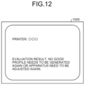
- the display control unit 211 of the information processing apparatus 20 causes the display unit 212 to display an evaluation abnormality screen 1000 indicating that the printing quality of the color chart CC is abnormal as illustrated in FIG. 12 to thereby give a warning to a user. In this case, as illustrated in FIG.
- the display control unit 211 causes the evaluation abnormality screen 1000 to display the identification information (the apparatus type, the IP address, or the like) on the image forming apparatus 10 that is identified by the color code C of the color chart CC for which the printing quality is determined as being abnormal. With this configuration, it is possible to easily recognize the image forming apparatus 10 whose printing quality is abnormal. Meanwhile, the display control unit 211 may cause the evaluation abnormality screen 1000 to display at least any of the paper type, the date and time, and page information, in addition to the identification information on the image forming apparatus 10 . Then, the determination process is terminated.
- the identification information the apparatus type, the IP address, or the like
- Steps S 161 to S 167 as described above If the determination process from Steps S 161 to S 167 as described above is terminated, the quality evaluation process is terminated.
- the color chart CC that is printed out by the image forming apparatus 10 includes the color evaluation patch CP used for the quality evaluation process and the color code C including at least the identification information on the image forming apparatus 10 .
- the information processing apparatus 20 identifies the color code C from the color information data of the color chart CC read by the image reading apparatus 30 , and identifies the image forming apparatus 10 on the basis of the identification information on the image forming apparatus 10 included in the color code C.
- the color code C of the color chart CC further includes the identification information on the paper type of the sheet on which the color chart CC is output, in addition to the identification information on the image forming apparatus 10 . If the paper type to be used is changed, a problem may occur in that a printing quality level as desired by a user is not achieved because a profile does not match a profile that is prepared in advance; however, as described above, in the present embodiment, the color chart CC includes the identification information on the paper type in addition to the identification information on the image forming apparatus 10 , so that it is possible to evaluate the printing quality with respect to the image forming apparatus 10 and the paper type, and it is possible to perform evaluation of quality in accordance with each of paper types.
- the color evaluation patch CP of the color chart CC includes the plurality of determination patches that are embedded to evaluate the printing quality of the image forming apparatus 10 .
- a color adjustment process may be performed; however, with use of the plurality of determination patches as described above, it is possible to evaluate (determine) the printing quality of the printed color chart CC. With this configuration, it is possible to prevent a situation in which the printing quality is not checked for a long time and printing is continued in a state in which the printing quality is not appropriate.
- the color code includes the identification information on the image forming apparatus 10 , the identification information on the paper type, the date and time of printing, and the identification information on the patch arrangement of the color chart CC, but embodiments are not limited to this example.
- An image forming system 1 according to a second embodiment will be described below, mainly in terms of a difference from the image forming system 1 according to the first embodiment.
- the operation has been explained in which the information processing apparatus 20 performs the determination process on the single color chart CC that is printed out by the image forming apparatus 10 .
- operation will be described in which at least the single image forming apparatus 10 performs the determination process by using a plurality of color charts.
- hardware configurations of the image forming apparatus 10 and the information processing apparatus 20 according to the present embodiment and a functional block configuration of the image forming system 1 are the same as those described in the first embodiment.
- the determination process of the present embodiment is advantageous in that, in an image forming apparatus capable of forming images on a plurality of sheets in one cycle of image forming operation, it is possible to evaluate printing quality of an entire image forming means (the plotter 531 or the like), for example.
- the one cycle of the image forming operation indicates, for example, one rotation of a transfer means for transferring an image onto a sheet or one rotation of a conveying means for conveying a sheet at the time of image formation.
- FIG. 13 is a diagram illustrating an example of a first color chart.
- FIG. 14 is a diagram illustrating an example of a second color chart.
- an overview of the operation performed by the image forming system 1 will be described based on the assumption that the determination process is performed by using two color charts. Meanwhile, the same operation as described below is performed in a determination process using three or more color charts.
- the job acquisition unit 102 of the image forming apparatus 10 acquires print jobs of two pieces of color chart data from the information processing apparatus 20 .
- the print control unit 103 of the image forming apparatus 10 causes the plotter 531 to print out the two color charts on the basis of the print jobs of the two pieces of color chart data acquired by the job acquisition unit 102 .
- the print control unit 103 causes color codes each including identification information on the image forming apparatus 10 , identification information on a paper type, date and time of printing, and identification information on the patch arrangement of the color charts to be printed.
- the two color charts are distinguished from each other by the identification information (page information) on the patch arrangement included in the printed color codes.
- a first color chart CCA is illustrated in FIG. 13 and a second color chart CCB is illustrated in FIG. 14 as examples of the two color charts that are printed out under the control of the print control unit 103 .
- the color chart CCA includes a color code CA and a color evaluation patch CPA, similarly to the first embodiment.
- the color chart CCB includes a color code CB and a color evaluation patch CPB, similarly to the first embodiment.
- Each of the color codes CA and CB is a code in which, as described above, the identification information on the image forming apparatus 10 that has printed out each of the color charts CCA and CCB, the identification information on the paper type used for printing, the date and time of printing, and the identification information on arrangement of each of the color evaluation patches CPA and CPB are coded as the color patches.
- color patches that indicate ends of each of the color codes CA and CB and that identify orientation of each of the color codes CA and CB are arranged at both ends of each of the color codes CA and CB.
- Each of the color evaluation patches CPA and CPB is a group of color patches for use to perform, by the information processing apparatus 20 , the quality evaluation process on the image forming apparatus 10 that is identified by each of the color codes CA and CB.
- the determination patches JP1 to JP7 are arranged at seven positions as the determination patches for evaluating the printing quality of the image forming apparatus 10 .
- the configurations of the determination patches JP1 to JP7 in each of the color evaluation patches CPA and CPB are the same as those of the first embodiment as described above.
- the calculation unit 206 of the information processing apparatus 20 calculates an average value or the like of the color measurement values for each of the patches P1 to P54 in the determination patches JP1 to JP7 of each of the color evaluation patches CPA and CPB acquired by the patch acquisition unit 205 .
- the color measurement values (Lab values) of the patches P1 in the determination patches JP1 to JP7 are represented by (L*A1_1, a*A1_1, b*A1_1), (L*A1_2, a*A1_2, b*A1_2), . . .
- the calculation unit 206 first calculates an average color measurement value (L*A1_ave, a*A1_ave, b*A1_ave) that is an average value of the color measurement values of the patches P1 by Expression (3) below.
- the color measurement values (Lab values) of the patches P1 in the determination patches JP1 to JP7 are represented by (L*B1_1, a*B1_1, b*B1_1), (L*B1_2, a*B1_2, b*B1_2), . . . , and (L*B1_7, a*B1_7, b*B1_7)
- the calculation unit 206 calculates an average color measurement value (L*B1_ave, a*B1_ave, b*B1_ave) that is an average value of the color measurement values by Expression (4) below.
- the calculation unit 206 calculates, as ⁇ EA1, a color difference between the calculated average color measurement value (L*A1_ave, a*A1_ave, b*A1_ave) and a predetermined reference value (L*1_std, a*1_std, b*1_std).
- the calculation unit 206 calculates color differences ⁇ EA2 to ⁇ EA54 by using the color measurement values (Lab values) of the patches P2 to P54 in the determination patches JP1 to JP7 in the color chart CCA.
- the calculation unit 206 calculates a color difference average value ⁇ EA_ave that is an average value of the calculated color differences ⁇ EA1 to ⁇ EA54 and calculates a maximum value ⁇ EA_Max.
- the calculation unit 206 calculates, as ⁇ EB1, a color difference between the calculated average color measurement value (L*B1 ave, a*B1 ave, b*B1 ave) and a predetermined reference value (L*1_std, a*1_std, b*1_std).
- the calculation unit 206 calculates color differences ⁇ EB2 to ⁇ EB54 by using the color measurement values (Lab values) of the patches P2 to P54 in the determination patches JP1 to JP7 in the color chart CCB. Then, the calculation unit 206 calculates a color difference average value ⁇ EB_ave that is an average value of the calculated color differences ⁇ EB1 to ⁇ EB54 and calculates a maximum value ⁇ EB_Max
- the calculation unit 206 calculates a difference ⁇ E1_AB between the average color measurement value (L*A1_ave, a*A1_ave, b*A1_ave) of the color chart CCA and the average color measurement value (L*B1_ave, a*B1_ave, b*B1_ave) of the color chart CCB.
- the calculation unit 206 calculates the differences ⁇ E2_AB to ⁇ E54_AB by using the color measurement values (Lab values) of the patches P2 to P54 in the determination patches JP1 to JP7.
- the calculation unit 206 stores the various calculated values in the storage unit 213 .
- the determination unit 207 of the information processing apparatus 20 determines whether the color difference average value ⁇ EA_ave and the maximum value ⁇ EA_Max calculated by the calculation unit 206 are respectively equal to or larger than the predetermined threshold Thresh1 and the predetermined Thresh2 by Expressions (2) above. Furthermore, the determination unit 207 determines whether the color difference average value ⁇ EB_ave and the maximum value ⁇ EB_Max calculated by the calculation unit 206 are respectively equal to or larger than the predetermined threshold Thresh1 and the predetermined threshold Thresh2 by Expressions (2) above.
- the determination unit 207 determines whether the differences ⁇ E1_AB to ⁇ E54_AB calculated by the calculation unit 206 are equal to or larger than predetermined thresholds Thresh3 by Expressions (5) below.
- the determination unit 207 determines that the printing quality of the color charts CCA and CCB is abnormal, and determines that the state of the image forming apparatus 10 identified by the identification unit 204 is abnormal. Meanwhile, in Expressions (5), the thresholds Thresh3 for the differences ⁇ E1_AB to ⁇ E54_AB need not always be the same values, but at least any of the thresholds may be a different value.
- the determination unit 207 stores a determination result in the storage unit 213 .
- FIG. 15 is a diagram illustrating an example of the flow of the determination process performed by the information processing apparatus according to the second embodiment.
- FIG. 16 is a diagram illustrating an example of an inter-page evaluation abnormality screen.
- the determination process performed by the information processing apparatus 20 in the quality evaluation process performed by the image forming system 1 according to the present embodiment will be described. Meanwhile, in the present embodiment, the determination process illustrated in FIG. 15 is performed at Step S 16 in the quality evaluation process illustrated in FIG. 8 .
- the patch acquisition unit 205 of the information processing apparatus 20 identifies portions corresponding to the determination patches JP1 to JP7 at the seven positions arranged in the color evaluation patch CPA from the color information data of the color chart CCA acquired by the color value acquisition unit 203 , and acquires the color measurement value (Lab value) of the patch P1 in each of the determination patches JP1 to JP7. Then, the process proceeds to Step S 162 a.
- the calculation unit 206 of the information processing apparatus 20 calculates the average color measurement value (L*A1_ave, a*A1_ave, b*A1_ave) that is an average value of the color measurement values of the patches P1 in the determination patches JP1 to JP7 acquired by the patch acquisition unit 205 , by Expression (3) above. Then, the process proceeds to Step S 163 a.
- the calculation unit 206 calculates, as ⁇ EA1, the color difference between the calculated average color measurement value (L*A1_ave, a*A1_ave, b*A1_ave) and the predetermined reference value (L*1_std, a*1_std, b*1_std) with respect to the color chart CCA.
- Step S 161 a to S 163 a The processes from Steps S 161 a to S 163 a are repeated on the patches P2 to P54 in the determination patches JP1 to JP7, and the color differences ⁇ EA2 to ⁇ EA54 are obtained. Then, the process proceeds to Step S 164 a.
- the calculation unit 206 calculates the color difference average value ⁇ EA_ave that is an average value of the calculated color differences ⁇ EA1 to ⁇ EA54 and calculates the maximum value ⁇ EA_Max. Then, the process proceeds to Step S 165 a.
- the determination unit 207 of the information processing apparatus 20 determines whether the color difference average value ⁇ EA_ave calculated by the calculation unit 206 is equal to or larger than the predetermined threshold Thresh1 by Expression (2) above. If the color difference average value ⁇ EA_ave is smaller than the threshold Thresh1 (YES at Step S 165 a ), the process proceeds to Step S 166 a , and, if the color difference average value ⁇ EA_ave is equal to or larger than the threshold Thresh1 the threshold Thresh1 (NO at Step S 165 a ), the process proceeds to Step S 168 a.
- the determination unit 207 determines whether the maximum value ⁇ EA_Max calculated by the calculation unit 206 is equal to or larger than the predetermined threshold Thresh2 by Expression (2) above. If the maximum value ⁇ EA_Max is smaller than the threshold Thresh2 (YES at Step S 166 a ), and if any of the patches P2 to P54 of the color charts CCA and CCB is not subjected to the process, the process returns to Step S 161 a , and the processes from Steps S 161 a to S 167 a are repeated. In contrast, if the maximum value ⁇ EA_Max is equal to or larger than the threshold Thresh2 (NO at Step S 166 a ), the process proceeds to Step S 168 a.
- the calculation unit 206 calculates the difference ⁇ E1_AB between the average color measurement value (L*A1_ave, a*A1_ave, b*A1_ave) of the color chart CCA and the average color measurement value (L*B1_ave, a*B1_ave, b*B1_ave) of the color chart CCB.
- the calculation unit 206 calculates the differences ⁇ E2_AB to ⁇ E54_AB by using the color measurement values (Lab values) of the patches P2 to P54 in the determination patches JP1 to JP7.
- the determination unit 207 determines whether the differences ⁇ E1_AB to ⁇ E54_AB calculated by the calculation unit 206 are equal to or larger than the predetermined thresholds Thresh3 by Expressions (5) above. If all of the differences ⁇ E1_AB to ⁇ E54_AB are smaller than the thresholds Thresh3 (YES at Step S 167 a ), the determination process is terminated, and, if at least any of the differences ⁇ E1_AB to ⁇ E54_AB is equal to or larger than the threshold Thresh3 (NO at Step S 167 a ), the process proceeds to Step S 168 a.
- the determination unit 207 determines that the printing quality of the color charts CCA and CCB is abnormal, and determines that the state of the image forming apparatus 10 identified by the identification unit 204 is abnormal.
- the display control unit 211 of the information processing apparatus 20 causes the display unit 212 to display the evaluation abnormality screen 1000 indicating that the printing quality of the color charts CCA and CCB is abnormal as illustrated in FIG. 12 above to thereby give a warning to a user. Furthermore, if it is determined that at least any of the differences ⁇ E1_AB to ⁇ E54_AB is equal to or larger than the threshold Thresh3, the display control unit 211 causes the display unit 212 to display an inter-page evaluation abnormality screen 1001 as illustrated in FIG. 16 indicating that the color values vary between the pages (the color charts CCA and CCB) to thereby give a warning to the user. Then, the determination process is terminated and the quality evaluation process is terminated.
- the plurality of color charts CC are printed out, whether the printing quality is abnormal is determined by using each of the color charts CC, and presence or absence of color variation between the plurality of color charts CC (between the pages) is determined. With this configuration, it is possible to confirm that the image forming apparatus 10 is in an appropriate state.
- An image forming system 1 according to a third embodiment will be described below, in terms of operation of displaying a graph of various values calculated by the calculation unit 206 .
- hardware configurations of the image forming apparatus 10 and the information processing apparatus 20 according to the present embodiment and a functional block configuration of the image forming system 1 are the same as those described in the first and the second embodiments.
- FIG. 17 is a diagram illustrating an example of a graph display screen. The graph display screen will be described with reference to FIG. 17 .
- a graph display screen 1100 illustrated in FIG. 17 is a screen in which, in the information processing apparatus 20 , various values calculated by the calculation unit 206 are chronologically displayed as a graph to check variation in quality evaluation.
- the graph display screen 1100 is displayed by the display unit 212 under the control of the display control unit 211 .
- the graph display screen 1100 includes a category selection region 1101 , an operation region 1102 , a display range setting region 1103 , a sheet selection region 1104 , an apparatus type selection region 1105 , and a graph display region 1106 .
- the graph display screen 1100 may be a software user interface installed in the information processing apparatus 20 , or a screen of a Web browser of a terminal device, an image forming apparatus, or the like for displaying a cloud computing service provided by a cloud computing server.
- the category selection region 1101 is a region for selecting a category.
- categories indicate sections in which the plurality of image forming apparatuses 10 are managed, and are categorized as, for example, an office, a building, a floor, and the like.
- the operation region 1102 is a region for performing operation of displaying a graph and setting various setting values.
- the operation region 1102 includes an update button 1102 a and a setting button 1102 b.
- the update button 1102 a is a button for updating a graph in the graph display region 1106 to latest contents.
- the setting button 1102 b is a button for selecting a value (for example, the color difference average value, the maximum value, the differences ⁇ E1_AB to ⁇ E54_AB in Expressions (5) above, or the like) that is to be displayed as a graph in the graph display region 1106 among the values calculated by the calculation unit 206 , and for setting a threshold for the selected value, for example.
- the display range setting region 1103 is a region for setting a display period in which the graph is displayed in the graph display region 1106 .
- a start time and an end time of the display period are set as illustrated in FIG. 17 .
- the sheet selection region 1104 is a region for setting a paper type for which a graph is displayed in the graph display region 1106 .
- the apparatus type selection region 1105 is a region for selecting the image forming apparatus 10 for which a graph is displayed in the graph display region 1106 .
- the apparatus type selection region 1105 for example, a list of IP addresses, apparatus numbers, or the like for identifying the image forming apparatuses 10 is displayed, and it is possible to select whether to display a graph in the graph display region 1106 for each of the image forming apparatuses 10 by changing ON and OFF of a checkbox provided for each of the image forming apparatuses 10 .
- the image forming apparatuses 10 that are displayed as a list in the apparatus type selection region 1105 belong to the category selected in the category selection region 1101 .
- the graph display region 1106 is a display region in which a graph of the value that is selected by the setting button 1102 b and that corresponds to the display period set by the display range setting region 1103 with respect to the paper type selected in the sheet selection region 1104 is displayed for each of the image forming apparatuses 10 that are selected in the apparatus type selection region 1105 . Furthermore, in the graph display region 1106 , a line of the threshold (a dashed line illustrated in FIG. 17 ) set by the setting button 1102 b is displayed, so that it is possible to check whether each of the values displayed on the graph is smaller than the threshold. In the example illustrated in FIG.
- graphs for apparatus types for example, the IP addresses as the identification information on the apparatus types
- apparatus types for example, the IP addresses as the identification information on the apparatus types
- FIG. 17 illustrates a state in which the plain paper, the gross paper, the matte paper, and the other paper are selected as the paper types in the sheet selection region 1104 , but as for the image forming apparatus 10 corresponding to the apparatus type of “192.168.100.20”, values corresponding to the plain paper and the other are not present, so that they are not displayed on the graph.
- the program is provided by being incorporated in ROM or the like in advance.
- the program executed by the image forming apparatus 10 and the information processing apparatus 20 may be provided by being recorded in a computer readable recording medium, such as a compact disc read only memory (CD-ROM), a flexible disk (FD), or a digital versatile disk (DVD) in a computer-installable or a computer-executable file format.
- CD-ROM compact disc read only memory
- FD flexible disk
- DVD digital versatile disk
- the program executed by the image forming apparatus 10 and the information processing apparatus 20 may be stored in a computer connected to a network, such as the Internet, and may be provided by being downloaded via the network. Furthermore, in each of the embodiments as described above, the program executed by the image forming apparatus 10 and the information processing apparatus 20 may be provided or distributed via a network, such as the Internet.
- the program executed by the image forming apparatus 10 and the information processing apparatus 20 has a module structure including at least any of the functional units as described above, and as actual hardware, the CPU 501 (the CPU 601 ) reads the program from the storage device as described above (for example, the system memory 502 , the auxiliary storage device 508 , the auxiliary storage device 605 , or the like) and executes the program, so that each of the functional units as described above is loaded and generated on a main storage device.
- the storage device as described above for example, the system memory 502 , the auxiliary storage device 508 , the auxiliary storage device 605 , or the like
- any of the above-described apparatus, devices or units can be implemented as a hardware apparatus, such as a special-purpose circuit or device, or as a hardware/software combination, such as a processor executing a software program.
- any one of the above-described and other methods of the present invention may be embodied in the form of a computer program stored in any kind of storage medium.
- storage mediums include, but are not limited to, flexible disk, hard disk, optical discs, magneto-optical discs, magnetic tapes, nonvolatile memory, semiconductor memory, read-only-memory (ROM), etc.
- any one of the above-described and other methods of the present invention may be implemented by an application specific integrated circuit (ASIC), a digital signal processor (DSP) or a field programmable gate array (FPGA), prepared by interconnecting an appropriate network of conventional component circuits or by a combination thereof with one or more conventional general purpose microprocessors or signal processors programmed accordingly.
- ASIC application specific integrated circuit
- DSP digital signal processor
- FPGA field programmable gate array
- Processing circuitry includes a programmed processor, as a processor includes circuitry.
- a processing circuit also includes devices such as an application specific integrated circuit (ASIC), digital signal processor (DSP), field programmable gate array (FPGA) and conventional circuit components arranged to perform the recited functions.
- ASIC application specific integrated circuit
- DSP digital signal processor
- FPGA field programmable gate array
Landscapes
- Engineering & Computer Science (AREA)
- Signal Processing (AREA)
- Multimedia (AREA)
- Health & Medical Sciences (AREA)
- General Health & Medical Sciences (AREA)
- Biomedical Technology (AREA)
- Theoretical Computer Science (AREA)
- General Engineering & Computer Science (AREA)
- General Physics & Mathematics (AREA)
- Physics & Mathematics (AREA)
- Human Computer Interaction (AREA)
- Quality & Reliability (AREA)
- Color Image Communication Systems (AREA)
- Accessory Devices And Overall Control Thereof (AREA)
- Record Information Processing For Printing (AREA)
- Investigating Materials By The Use Of Optical Means Adapted For Particular Applications (AREA)
- Image Processing (AREA)
- Facsimile Image Signal Circuits (AREA)
Abstract
Description
Claims (18)
Applications Claiming Priority (2)
| Application Number | Priority Date | Filing Date | Title |
|---|---|---|---|
| JP2020-180943 | 2020-10-28 | ||
| JP2020180943A JP7585715B2 (en) | 2020-10-28 | 2020-10-28 | Color chart, information processing device and information processing system |
Publications (2)
| Publication Number | Publication Date |
|---|---|
| US20220131982A1 US20220131982A1 (en) | 2022-04-28 |
| US12063328B2 true US12063328B2 (en) | 2024-08-13 |
Family
ID=78621680
Family Applications (1)
| Application Number | Title | Priority Date | Filing Date |
|---|---|---|---|
| US17/504,872 Active US12063328B2 (en) | 2020-10-28 | 2021-10-19 | Color chart, information processing apparatus, and information processing system |
Country Status (3)
| Country | Link |
|---|---|
| US (1) | US12063328B2 (en) |
| EP (1) | EP3993381B1 (en) |
| JP (1) | JP7585715B2 (en) |
Families Citing this family (4)
| Publication number | Priority date | Publication date | Assignee | Title |
|---|---|---|---|---|
| JP7585715B2 (en) | 2020-10-28 | 2024-11-19 | 株式会社リコー | Color chart, information processing device and information processing system |
| JP7661687B2 (en) * | 2020-10-29 | 2025-04-15 | 株式会社リコー | Color chart, information processing device and information processing system |
| JP7793947B2 (en) * | 2021-11-09 | 2026-01-06 | 株式会社リコー | Information processing device, image forming system, information processing method and program |
| JP2024033661A (en) * | 2022-08-31 | 2024-03-13 | セイコーエプソン株式会社 | Information processing device, information processing method, and information processing system |
Citations (33)
| Publication number | Priority date | Publication date | Assignee | Title |
|---|---|---|---|---|
| US4980544A (en) | 1987-04-22 | 1990-12-25 | Abbott Laboratories | Optical code reader and format |
| US6048117A (en) * | 1998-05-08 | 2000-04-11 | Xerox Corporation | Network-based system for color calibration of printers |
| EP1091566A2 (en) | 1999-10-05 | 2001-04-11 | Eastman Kodak Company | Output adjustment for digital printers |
| US20050243316A1 (en) * | 2004-04-30 | 2005-11-03 | Cargill Mark A | Color code for color measurement system |
| US20060028699A1 (en) * | 2000-11-10 | 2006-02-09 | Xerox Corporation | Patch codes for color calibration job identification encoding |
| US20070153340A1 (en) | 2005-12-28 | 2007-07-05 | Canon Kabushiki Kaisha | Color processing method and apparatus thereof |
| JP2008072343A (en) | 2006-09-13 | 2008-03-27 | Canon Inc | Profile creation apparatus and method |
| JP2008209436A (en) | 2007-02-23 | 2008-09-11 | Fuji Xerox Co Ltd | Image forming system |
| US20080239344A1 (en) | 2007-03-31 | 2008-10-02 | Xerox Corporation | Color printer characterization or calibration to correct for spatial non-uniformity |
| US20080259365A1 (en) * | 2006-09-13 | 2008-10-23 | Seiko Epson Corporation | Evaluation of calibration precision |
| US20100067025A1 (en) | 2008-09-16 | 2010-03-18 | Fuji Xerox Co., Ltd. | Image forming system, image forming apparatus, terminal device, gradation characteristic measuring method, computer readable medium storing program and gradation characteristic measurement sheet |
| US20110286018A1 (en) | 2010-05-20 | 2011-11-24 | Canon Kabushiki Kaisha | Image forming apparatus, control method thereof, and storage medium |
| US20120086962A1 (en) | 2005-12-22 | 2012-04-12 | Xerox Corporation | Method and system for color correction using both spatial correction and printer calibration techniques |
| US20120133961A1 (en) | 2010-11-30 | 2012-05-31 | Henderson Thomas A | Producing calibration target for printer |
| US20140209682A1 (en) * | 2013-01-25 | 2014-07-31 | Hewlett-Packard Development Company, L.P. | Characterization of color charts |
| US20140375672A1 (en) | 2013-06-25 | 2014-12-25 | Fuji Xerox Co., Ltd. | Image processing apparatus, image adjustment system, image processing method, and recording medium |
| US20160261775A1 (en) * | 2015-03-05 | 2016-09-08 | Samsung Electronics Co., Ltd. | Method and device for color compensation |
| US20160274520A1 (en) * | 2015-03-17 | 2016-09-22 | Takashi Soma | Image forming apparatus, image processing method, and computer-readable recording medium |
| US20160301830A1 (en) | 2015-04-13 | 2016-10-13 | Konica Minolta, Inc. | Print color managing apparatus, chart utilization control method, and non-transitory computer-readable storage medium storing chart utilization control program |
| JP2017055282A (en) | 2015-09-10 | 2017-03-16 | 富士ゼロックス株式会社 | Image quality management and adjustment device and program |
| US20170085726A1 (en) | 2015-09-17 | 2017-03-23 | Fuji Xerox Co., Ltd. | Color patch generation apparatus and image forming apparatus, and non- transitory computer readable medium |
| US20170099414A1 (en) | 2015-10-01 | 2017-04-06 | Konica Minolta, Inc. | Printer, non-transitory computer-readable storage medium storing program for creating scanner profile and method of creating scanner profile |
| US20170270655A1 (en) | 2016-03-16 | 2017-09-21 | Shuhei Watanabe | Texture evaluation apparatus, texture evaluation method, and computer-readable recording medium |
| US20180259394A1 (en) | 2017-03-09 | 2018-09-13 | Takayuki Gotoh | Color measurement apparatus and color information processing apparatus |
| US10129438B2 (en) | 2016-07-11 | 2018-11-13 | Konica Minolta, Inc. | Color conversion apparatus, non-transitory recording medium storing color conversion program and color conversion method |
| US20180350059A1 (en) | 2017-05-31 | 2018-12-06 | Shuhei Watanabe | Evaluation device and recording medium storing evaluation program |
| US20190147308A1 (en) | 2017-11-10 | 2019-05-16 | Seiko Epson Corporation | Information processing device, information processing method, program, and color chart |
| US20190238724A1 (en) | 2018-01-31 | 2019-08-01 | Ricoh Company, Ltd. | Image processing apparatus, image processing method, and medium |
| US20190250040A1 (en) | 2018-02-15 | 2019-08-15 | Ricoh Company, Ltd. | Spectral characteristic acquiring apparatus, image forming apparatus, image forming system, image forming apparatus management system, and image forming apparatus management method |
| US20200018650A1 (en) | 2018-07-13 | 2020-01-16 | Takuroh SONE | Evaluator, measurement apparatus, evaluating method, and non-transitory recording medium |
| US20200300701A1 (en) | 2019-03-20 | 2020-09-24 | Ricoh Company, Ltd. | Spectral property acquisition apparatus and image forming apparatus |
| JP2020153829A (en) | 2019-03-20 | 2020-09-24 | 株式会社リコー | Image formation information acquisition method, profile creation system and color chart |
| EP3993381A1 (en) | 2020-10-28 | 2022-05-04 | Ricoh Company, Ltd. | Color chart, information processing apparatus, and information processing system |
Family Cites Families (7)
| Publication number | Priority date | Publication date | Assignee | Title |
|---|---|---|---|---|
| JP2001260407A (en) * | 2000-03-22 | 2001-09-25 | Konica Corp | Chart for calibrating image processing apparatus, forming method and processing method for color data for calibration and image processing apparatus |
| JP2007055282A (en) | 2005-08-22 | 2007-03-08 | Yanmar Co Ltd | Operating device |
| JP5602196B2 (en) * | 2012-08-08 | 2014-10-08 | 富士フイルム株式会社 | Print color evaluation system, method and program |
| JP6032078B2 (en) * | 2013-03-21 | 2016-11-24 | 富士ゼロックス株式会社 | Color variation monitoring apparatus, image forming system, and program |
| JP6123765B2 (en) * | 2014-09-16 | 2017-05-10 | コニカミノルタ株式会社 | Information processing system, printing apparatus, information processing method, and information processing program |
| JP6151673B2 (en) * | 2014-09-16 | 2017-06-21 | 富士フイルム株式会社 | Print color prediction method and apparatus, profile generation method and apparatus, and program |
| JP7141021B2 (en) * | 2018-10-29 | 2022-09-22 | コニカミノルタ株式会社 | Color chart generation method, color chart generation device and program |
-
2020
- 2020-10-28 JP JP2020180943A patent/JP7585715B2/en active Active
-
2021
- 2021-10-19 US US17/504,872 patent/US12063328B2/en active Active
- 2021-10-27 EP EP21205092.6A patent/EP3993381B1/en active Active
Patent Citations (39)
| Publication number | Priority date | Publication date | Assignee | Title |
|---|---|---|---|---|
| US4980544A (en) | 1987-04-22 | 1990-12-25 | Abbott Laboratories | Optical code reader and format |
| US6048117A (en) * | 1998-05-08 | 2000-04-11 | Xerox Corporation | Network-based system for color calibration of printers |
| EP1091566A2 (en) | 1999-10-05 | 2001-04-11 | Eastman Kodak Company | Output adjustment for digital printers |
| US20060028699A1 (en) * | 2000-11-10 | 2006-02-09 | Xerox Corporation | Patch codes for color calibration job identification encoding |
| US20050243316A1 (en) * | 2004-04-30 | 2005-11-03 | Cargill Mark A | Color code for color measurement system |
| US20120086962A1 (en) | 2005-12-22 | 2012-04-12 | Xerox Corporation | Method and system for color correction using both spatial correction and printer calibration techniques |
| US20070153340A1 (en) | 2005-12-28 | 2007-07-05 | Canon Kabushiki Kaisha | Color processing method and apparatus thereof |
| JP2007181142A (en) | 2005-12-28 | 2007-07-12 | Canon Inc | Color processing method and apparatus |
| US20080259365A1 (en) * | 2006-09-13 | 2008-10-23 | Seiko Epson Corporation | Evaluation of calibration precision |
| JP2008072343A (en) | 2006-09-13 | 2008-03-27 | Canon Inc | Profile creation apparatus and method |
| JP2008209436A (en) | 2007-02-23 | 2008-09-11 | Fuji Xerox Co Ltd | Image forming system |
| US20080239344A1 (en) | 2007-03-31 | 2008-10-02 | Xerox Corporation | Color printer characterization or calibration to correct for spatial non-uniformity |
| US20100067025A1 (en) | 2008-09-16 | 2010-03-18 | Fuji Xerox Co., Ltd. | Image forming system, image forming apparatus, terminal device, gradation characteristic measuring method, computer readable medium storing program and gradation characteristic measurement sheet |
| US20120147427A1 (en) | 2008-09-16 | 2012-06-14 | Fuji Xerox Co., Ltd. | Image forming system, image forming apparatus, terminal device, gradation characteristic measuring method, computer readable medium storing program and gradation characteristic measurement sheet |
| US20110286018A1 (en) | 2010-05-20 | 2011-11-24 | Canon Kabushiki Kaisha | Image forming apparatus, control method thereof, and storage medium |
| US20120133961A1 (en) | 2010-11-30 | 2012-05-31 | Henderson Thomas A | Producing calibration target for printer |
| US20140209682A1 (en) * | 2013-01-25 | 2014-07-31 | Hewlett-Packard Development Company, L.P. | Characterization of color charts |
| US20140375672A1 (en) | 2013-06-25 | 2014-12-25 | Fuji Xerox Co., Ltd. | Image processing apparatus, image adjustment system, image processing method, and recording medium |
| US20160261775A1 (en) * | 2015-03-05 | 2016-09-08 | Samsung Electronics Co., Ltd. | Method and device for color compensation |
| US20160274520A1 (en) * | 2015-03-17 | 2016-09-22 | Takashi Soma | Image forming apparatus, image processing method, and computer-readable recording medium |
| US20160301830A1 (en) | 2015-04-13 | 2016-10-13 | Konica Minolta, Inc. | Print color managing apparatus, chart utilization control method, and non-transitory computer-readable storage medium storing chart utilization control program |
| JP2017055282A (en) | 2015-09-10 | 2017-03-16 | 富士ゼロックス株式会社 | Image quality management and adjustment device and program |
| US20170078496A1 (en) | 2015-09-10 | 2017-03-16 | Fuji Xerox Co., Ltd. | Image quality control and adjustment apparatus, image quality control and adjustment method, and non-transitory computer readable medium |
| US20170085726A1 (en) | 2015-09-17 | 2017-03-23 | Fuji Xerox Co., Ltd. | Color patch generation apparatus and image forming apparatus, and non- transitory computer readable medium |
| US20170099414A1 (en) | 2015-10-01 | 2017-04-06 | Konica Minolta, Inc. | Printer, non-transitory computer-readable storage medium storing program for creating scanner profile and method of creating scanner profile |
| US20170270655A1 (en) | 2016-03-16 | 2017-09-21 | Shuhei Watanabe | Texture evaluation apparatus, texture evaluation method, and computer-readable recording medium |
| US10129438B2 (en) | 2016-07-11 | 2018-11-13 | Konica Minolta, Inc. | Color conversion apparatus, non-transitory recording medium storing color conversion program and color conversion method |
| US20180259394A1 (en) | 2017-03-09 | 2018-09-13 | Takayuki Gotoh | Color measurement apparatus and color information processing apparatus |
| US20180350059A1 (en) | 2017-05-31 | 2018-12-06 | Shuhei Watanabe | Evaluation device and recording medium storing evaluation program |
| US20190147308A1 (en) | 2017-11-10 | 2019-05-16 | Seiko Epson Corporation | Information processing device, information processing method, program, and color chart |
| JP2019087962A (en) | 2017-11-10 | 2019-06-06 | セイコーエプソン株式会社 | INFORMATION PROCESSING APPARATUS, INFORMATION PROCESSING METHOD, PROGRAM, AND COLOR CHART |
| US20190238724A1 (en) | 2018-01-31 | 2019-08-01 | Ricoh Company, Ltd. | Image processing apparatus, image processing method, and medium |
| US20190250040A1 (en) | 2018-02-15 | 2019-08-15 | Ricoh Company, Ltd. | Spectral characteristic acquiring apparatus, image forming apparatus, image forming system, image forming apparatus management system, and image forming apparatus management method |
| JP2019138883A (en) | 2018-02-15 | 2019-08-22 | 株式会社リコー | Spectral characteristic acquisition device, image forming apparatus, image forming system, management system for image forming apparatus, and management method for image forming apparatus |
| US20200018650A1 (en) | 2018-07-13 | 2020-01-16 | Takuroh SONE | Evaluator, measurement apparatus, evaluating method, and non-transitory recording medium |
| US20200300701A1 (en) | 2019-03-20 | 2020-09-24 | Ricoh Company, Ltd. | Spectral property acquisition apparatus and image forming apparatus |
| JP2020153829A (en) | 2019-03-20 | 2020-09-24 | 株式会社リコー | Image formation information acquisition method, profile creation system and color chart |
| JP2020153814A (en) | 2019-03-20 | 2020-09-24 | 株式会社リコー | Spectroscopic property acquisition device |
| EP3993381A1 (en) | 2020-10-28 | 2022-05-04 | Ricoh Company, Ltd. | Color chart, information processing apparatus, and information processing system |
Non-Patent Citations (8)
| Title |
|---|
| European Office Action dated Feb. 13, 2024 issued in European Appln. No. 21204314.5. |
| Extended European Search Report dated Feb. 17, 2022 issued in corresponding European Appln. No. 21205092.6. |
| Extended European Search Report dated Mar. 10, 2022 issued in corresponding European Appln. No. 21204314.5. |
| Notice of Allowance dated Sep. 7, 2023, issued in corresponding U.S. Appl. No. 17/512,960. |
| Office action dated Dec. 9, 2022, issued in corresponding U.S. Appl. No. 17/512,960. |
| Office action dated Jun. 1, 2023, issued in corresponding U.S. Appl. No. 17/512,960. |
| Office Action dated Jun. 24, 2022, issued in corresponding U.S. Appl. No. 17/512,960. |
| Office Action dated Jun. 4, 2024 issued in corresponding Japanese Patent Application No. 2020-180943. |
Also Published As
| Publication number | Publication date |
|---|---|
| JP2022071780A (en) | 2022-05-16 |
| EP3993381B1 (en) | 2024-12-04 |
| JP7585715B2 (en) | 2024-11-19 |
| EP3993381A1 (en) | 2022-05-04 |
| US20220131982A1 (en) | 2022-04-28 |
Similar Documents
| Publication | Publication Date | Title |
|---|---|---|
| US12063328B2 (en) | Color chart, information processing apparatus, and information processing system | |
| US11895284B2 (en) | Color chart for performing color and in-plane unevenness on an image forming apparatus | |
| JP6221661B2 (en) | Inspection device, inspection system, inspection method, and printing system | |
| JP6613641B2 (en) | Inspection device, threshold changing method, and program | |
| JP2019158994A (en) | Diagnostic system, diagnostic method, image forming apparatus, and program | |
| JP6848286B2 (en) | Inspection equipment, inspection methods and programs | |
| US11899989B2 (en) | Information processing apparatus, image forming system, information processing method, and non-transitory recording medium for monitoring color matching processing | |
| US11089181B2 (en) | Image forming apparatus, system and program product acquiring color information of image printed on first side before printing on second side of print medium | |
| JP6705305B2 (en) | Inspection device, inspection method and program | |
| JP2016178557A (en) | Image processing apparatus, correction method, and program | |
| JP2013251611A (en) | Image processing apparatus, control method of the same, and program | |
| JP5760562B2 (en) | Reading apparatus and reading method | |
| US11736625B1 (en) | Image forming apparatus and reading apparatus using information added to a recording medium to control output of a reading result of a diagnostic image formed thereon | |
| US11785147B1 (en) | Information processing apparatus, product, and method wherein a print from one image forming apparatus is read by another and a screen is generated including diagnostic results and image forming apparatus information | |
| US20250301068A1 (en) | Image diagnosis system, non-transitory computer readable medium storing program, and image diagnosis method | |
| US11968333B2 (en) | Image forming apparatus | |
| US20250306818A1 (en) | Information processing system, non-transitory computer readable medium and information processing method | |
| US20240291931A1 (en) | Method of creating color chart data, information processing apparatus for creating color chart data, color chart, image forming system, and non-transitory recording medium | |
| US20260025471A1 (en) | Inspection system, inspection method, and non-transitory recording medium | |
| US20250306823A1 (en) | Information processing system, non-transitory computer readable medium and method | |
| US20230308551A1 (en) | Image forming apparatus, non-transitory computer readable medium, and image forming method | |
| JP6844522B2 (en) | Image processing device | |
| US20210105379A1 (en) | Image forming apparatus, storage medium, and control method | |
| JP2025147992A (en) | Information processing system and information processing program | |
| JP5173978B2 (en) | Smudge inspection device for document reading unit, image forming apparatus, and method for soiling inspection of document reading unit |
Legal Events
| Date | Code | Title | Description |
|---|---|---|---|
| FEPP | Fee payment procedure |
Free format text: ENTITY STATUS SET TO UNDISCOUNTED (ORIGINAL EVENT CODE: BIG.); ENTITY STATUS OF PATENT OWNER: LARGE ENTITY |
|
| AS | Assignment |
Owner name: RICOH COMPANY, LTD., JAPAN Free format text: ASSIGNMENT OF ASSIGNORS INTEREST;ASSIGNORS:KIHARA, HIDEYUKI;TANEDA, YUSUKE;NAGATA, YUTA;SIGNING DATES FROM 20211012 TO 20211013;REEL/FRAME:057864/0323 |
|
| STPP | Information on status: patent application and granting procedure in general |
Free format text: DOCKETED NEW CASE - READY FOR EXAMINATION |
|
| STPP | Information on status: patent application and granting procedure in general |
Free format text: NON FINAL ACTION MAILED |
|
| STPP | Information on status: patent application and granting procedure in general |
Free format text: RESPONSE TO NON-FINAL OFFICE ACTION ENTERED AND FORWARDED TO EXAMINER |
|
| STPP | Information on status: patent application and granting procedure in general |
Free format text: NON FINAL ACTION MAILED |
|
| STPP | Information on status: patent application and granting procedure in general |
Free format text: FINAL REJECTION MAILED |
|
| STPP | Information on status: patent application and granting procedure in general |
Free format text: DOCKETED NEW CASE - READY FOR EXAMINATION |
|
| STPP | Information on status: patent application and granting procedure in general |
Free format text: NON FINAL ACTION MAILED |
|
| STPP | Information on status: patent application and granting procedure in general |
Free format text: RESPONSE TO NON-FINAL OFFICE ACTION ENTERED AND FORWARDED TO EXAMINER |
|
| STPP | Information on status: patent application and granting procedure in general |
Free format text: FINAL REJECTION MAILED |
|
| STPP | Information on status: patent application and granting procedure in general |
Free format text: RESPONSE AFTER FINAL ACTION FORWARDED TO EXAMINER |
|
| STPP | Information on status: patent application and granting procedure in general |
Free format text: NOTICE OF ALLOWANCE MAILED -- APPLICATION RECEIVED IN OFFICE OF PUBLICATIONS |
|
| ZAAB | Notice of allowance mailed |
Free format text: ORIGINAL CODE: MN/=. |
|
| STPP | Information on status: patent application and granting procedure in general |
Free format text: PUBLICATIONS -- ISSUE FEE PAYMENT VERIFIED |
|
| STCF | Information on status: patent grant |
Free format text: PATENTED CASE |