US12062965B2 - Offset triggered cantilever actuated generator - Google Patents
Offset triggered cantilever actuated generator Download PDFInfo
- Publication number
- US12062965B2 US12062965B2 US17/839,473 US202217839473A US12062965B2 US 12062965 B2 US12062965 B2 US 12062965B2 US 202217839473 A US202217839473 A US 202217839473A US 12062965 B2 US12062965 B2 US 12062965B2
- Authority
- US
- United States
- Prior art keywords
- magnet
- row
- magnets
- axis
- coil
- Prior art date
- Legal status (The legal status is an assumption and is not a legal conclusion. Google has not performed a legal analysis and makes no representation as to the accuracy of the status listed.)
- Active, expires
Links
Images


Classifications
-
- F—MECHANICAL ENGINEERING; LIGHTING; HEATING; WEAPONS; BLASTING
- F03—MACHINES OR ENGINES FOR LIQUIDS; WIND, SPRING, OR WEIGHT MOTORS; PRODUCING MECHANICAL POWER OR A REACTIVE PROPULSIVE THRUST, NOT OTHERWISE PROVIDED FOR
- F03G—SPRING, WEIGHT, INERTIA OR LIKE MOTORS; MECHANICAL-POWER PRODUCING DEVICES OR MECHANISMS, NOT OTHERWISE PROVIDED FOR OR USING ENERGY SOURCES NOT OTHERWISE PROVIDED FOR
- F03G5/00—Devices for producing mechanical power from muscle energy
- F03G5/06—Devices for producing mechanical power from muscle energy other than of endless-walk type
- F03G5/062—Devices for producing mechanical power from muscle energy other than of endless-walk type driven by humans
- F03G5/065—Devices for producing mechanical power from muscle energy other than of endless-walk type driven by humans operated by the hand
-
- H—ELECTRICITY
- H01—ELECTRIC ELEMENTS
- H01F—MAGNETS; INDUCTANCES; TRANSFORMERS; SELECTION OF MATERIALS FOR THEIR MAGNETIC PROPERTIES
- H01F7/00—Magnets
- H01F7/02—Permanent magnets [PM]
- H01F7/0273—Magnetic circuits with PM for magnetic field generation
-
- H—ELECTRICITY
- H02—GENERATION; CONVERSION OR DISTRIBUTION OF ELECTRIC POWER
- H02K—DYNAMO-ELECTRIC MACHINES
- H02K1/00—Details of the magnetic circuit
- H02K1/06—Details of the magnetic circuit characterised by the shape, form or construction
- H02K1/34—Reciprocating, oscillating or vibrating parts of the magnetic circuit
-
- H—ELECTRICITY
- H02—GENERATION; CONVERSION OR DISTRIBUTION OF ELECTRIC POWER
- H02K—DYNAMO-ELECTRIC MACHINES
- H02K35/00—Generators with reciprocating, oscillating or vibrating coil system, magnet, armature or other part of the magnetic circuit
- H02K35/02—Generators with reciprocating, oscillating or vibrating coil system, magnet, armature or other part of the magnetic circuit with moving magnets and stationary coil systems
-
- H—ELECTRICITY
- H02—GENERATION; CONVERSION OR DISTRIBUTION OF ELECTRIC POWER
- H02K—DYNAMO-ELECTRIC MACHINES
- H02K7/00—Arrangements for handling mechanical energy structurally associated with dynamo-electric machines, e.g. structural association with mechanical driving motors or auxiliary dynamo-electric machines
- H02K7/18—Structural association of electric generators with mechanical driving motors, e.g. with turbines
- H02K7/1807—Rotary generators
- H02K7/1853—Rotary generators driven by intermittent forces
-
- F—MECHANICAL ENGINEERING; LIGHTING; HEATING; WEAPONS; BLASTING
- F03—MACHINES OR ENGINES FOR LIQUIDS; WIND, SPRING, OR WEIGHT MOTORS; PRODUCING MECHANICAL POWER OR A REACTIVE PROPULSIVE THRUST, NOT OTHERWISE PROVIDED FOR
- F03G—SPRING, WEIGHT, INERTIA OR LIKE MOTORS; MECHANICAL-POWER PRODUCING DEVICES OR MECHANISMS, NOT OTHERWISE PROVIDED FOR OR USING ENERGY SOURCES NOT OTHERWISE PROVIDED FOR
- F03G5/00—Devices for producing mechanical power from muscle energy
- F03G5/06—Devices for producing mechanical power from muscle energy other than of endless-walk type
Definitions
- the present invention relates to energy harvesting electrical generators, in particular, single-motion or impulse actuated electrical generators with a damped sinusoidal output that are superior in instantaneous triggered resultant output compared to instantaneous triggered snap-action magnetic circuit types that have a short single electrical pulse output of a typical effective time duration of 2 milliseconds.
- Energy harvesting devices cover a wide range of low to high power generation for many applications, especially generating electrical energy from mechanical motion produced by intentional operator or environmental incidental action and have size versus efficiency choices. For those low power applications many are significantly limited; and in general, offer inadequate wide range product utilization. Further efforts by some prior art related to continuous or short burst types have not shown significant improvements and do not show any greater problem or application understanding likely to provide any significant improvements thereof.
- the present invention introduces and teaches a novel plurality magnet arrangement having distinct advantages and novelty over prior art whereby the present invention teaches a plurality magnet arrangement of a matrix of rows and columns has a novel method means of reducing the counter electromotive force (voltage) during electrically connecting a load to the coil winding terminals and this has novelty in extending the time duration of the damped sinusoidal output voltage waveform and this is accomplished by altering the magnet field alignment on the plurality of the magnet matrix comprise of rows and columns of plurality magnets in such a manner that there are at times a co-existing combination of changing attractive and repelling magnetic field region all throughout the coil winding volume.
- the present invention also provides and teaches that a variable speed range of motion triggering, can be supplied by an external push force on a forked-cantilever that is movable and rotating on its offset inline axles that are on the opposite end of the fork arrangement, where the two fork end tabs come in momentary contact with a rotatable centre magnet disposed within a coil; and any trigger action causes an induced electromotive force (voltage) established at the coil terminals by a relativistic electrodynamic movement of electrical charge (electrons) within the coil winding in a continuous or pulsed periodic rotational energy harvesting generator.
- a variable speed range of motion triggering can be supplied by an external push force on a forked-cantilever that is movable and rotating on its offset inline axles that are on the opposite end of the fork arrangement, where the two fork end tabs come in momentary contact with a rotatable centre magnet disposed within a coil; and any trigger action causes an induced electromotive force (voltage) established at the coil terminals
- the forked cantilever movement progression is slow action or fast action
- the forked cantilever moves the centre movable magnet (responsible for power generation) past the trigger release point of an dual set of angled plurality tooth arrangement situated on opposite sides of the centre movable magnet enclosure adjacent to its common inline axles
- the individual response of the power generating centre movable magnet (in its enclosure) disposed within the centre of the coil in conjunction with the first and second set of a plurality of fixed position focusing magnets situated at opposite ends of the coil creates “geometrically distorted” and “changing magnetic field tensors” surrounding and passing through the coil winding; a varying power envelope is produced.
- the overall “relativistic moving charge effect” of inducing a voltage at the generator coil terminals is further enhanced by utilizing the two plurality sets of fixed directive (counter emf reducing) magnets, fixed on opposite ends of the coil, to concentrate the magnetic field throughout the generator coil winding; and with every movement of the cantilever trigger, in momentary and periodic mechanical connexin to the centred situated rotatable magnet, a voltage is produced at the coil terminals due to the relativistic movement of charge by magnetic field changes
- a damped sinusoidal alternating voltage with typical effective AC wave duration time under a “no-load” condition of several hundreds of milliseconds, is established at the coil terminals; and with the novelty of the present embodiment connecting a load to the coil will produce a substantially less decrease in the effective AC wave duration time.
- the novel structure utilizes modified effects of Ampere's Law, Lenz's Law, and the Lorentz Force in producing substantially less decrease in AC wave duration time.
- the EMF Electrotive Force, (defined below) generated by special relativistic charge movement and conforming to Faraday's law of induction (the flow of charge (current)) through a coil around an electrical complete circuit due to relative movement or change of a coil's magnetic field) is the phenomenon underlying electrical generators; however, most texts covering the Faraday Principle illustrates a moving coil through a stationary magnetic field source (a magnet), with the present invention the converse holds true where an independent magnet can be moved and rotated within the centre of an electric coil and whereby the coil has fixed on its opposite sides, two plurality sets non-movable fixed magnets.
- an electromotive force voltage
- the coil wire terminals are connected to an electrical load, current will flow in the completed circuit, and thus electrical energy is generated, converting the mechanical energy of motion to electrical energy, thus ‘harvesting’ mechanical energy as electrical energy for some application usage.
- magnetism due to electrons Apart from charge and mass, electrons also have an intrinsic magnetic moment that can be explained only through relativistic quantum mechanics. Thus, magnetism of a bar magnet is also a relativistic effect. Please note that magnetism in a bar magnet is because of the election's spin, orbital motion and magneto-crystalline anisotropy.
- Materials with high magnetic anisotropy usually have high coercivity, that is, they are hard to demagnetize. These are called “hard” ferromagnetic materials and are used to make permanent magnets.
- the high anisotropy of rare-earth metals is mainly responsible for the strength of rare-earth magnets.
- a powerful magnetic field aligns the microcrystalline grains of the metal such that their “easy” axes of magnetization all point in the same direction, freezing a strong magnetic field into the material.
- the strongest permanent magnets available today rare earth magnets such as but not limited to, Neodymium (Nd,Pr)FeB and Samarium-Colbalt SmCo varieties having magnetic properties due to the interaction of the electron's spin and orbital motion with the potential created by the material lattice. Permanent magnets are not simply produced from having excess, non-cancelled electronic spins or some such. The requirement needed crystalline or shape features.
- EMF Electromotive Force
- Emf electromotive force
- Electromotive force is directly related to the source of potential difference, e.g. such as the particular combination of the number of turns and the thickness of the wire in a coil winding in a generator.
- emf differs from the voltage output of the device when current flows.
- the voltage across the terminals of a coil winding for example, is less than the emf when the coil winding supplies current, and it declines further as the coil winding is electrically loaded down.
- output voltage will equal emf.
- I is positive if current flows away from the positive terminal.
- the larger the current the smaller the terminal voltage.
- the larger the internal resistance the smaller the terminal voltage.
- the preferred embodiment of the present invention has a plurality of rows and columns of magnets up as a matrix, and for exemplary embodiments of this present invention, there are rare earth magnets disk magnets arranged in a three column by two row array (matrix), where each column member magnet is separated proximal from each other and each row of three member magnets is separated distal from each other; for this present invention, including the novel feature having in each row, the magnetic pole alignment of a member magnet opposite to an adjacent member magnet.
- Other embodiments may include a larger number of magnets in each row, and may have all adjacent row magnets pole alignment oppositely disposed.
- the arrangement is such that their respective “up & down” magnetic pole circuitous alignment exists so that there is a first set of a 1st member S ⁇ N with (poled S facing up), a 2 nd member with (poled N N ⁇ S facing up), and a 3 rd member with S ⁇ N (poled S facing up) and they are all separated on one side proximal of a coil bobbin with its wire winding and on a side opposite the coil bobbin with its wire winding is a disposed second set of a S ⁇ N 1st member with (poled s facing up), a 2 nd N ⁇ S member with (poled N facing up), S ⁇ N and a 3 rd member with (poled S facing up); and disposed centred within the coil bobbin, is a rotatable about its axis, magnet.
- [6] There exists a static attractive magnetic field between the 3rd magnet of the first row and the 3 rd magnet of the second row distal.
- [7] There is disposed a first changing differential function magnetic field region between the 2nd magnet member (centre position) of the first row and a first width side of the rotatable centre magnet disposed and free to rotate about its axis of rotation and
- [8] there is disposed a second changing differential function magnetic field region between the 2 nd magnet member (centre position) of the second row and a second opposite width side of the rotatable centre magnet disposed and free to rotate about its axis of rotation.
- the induced currents exhibit diamagnetic-like repulsion effects.
- a conductive object will experience a repulsion force. This can lift objects against gravity, though with continual power input to replace the energy dissipated by the eddy currents.
- An example application is separation of aluminum cans from other metals in an eddy current separator. Ferrous metals cling to the magnet, and aluminum (and other nonferrous conductors) are forced away from the magnet; this A cross section through a linear motor placed above a thick aluminium slab. As the linear induction motor's field pattern sweeps to the left, eddy currents are left behind in the metal and this causes the field lines to lean. can separate a waste stream into ferrous and non-ferrous scrap metal.
- the overall force of eddy currents can be attractive, for example, where the flux lines are past 90 degrees to a surface, the induced currents in a nearby conductor cause a force that pushes a rotatable magnet towards a coil.
- the “Magnet Array” with its novel arrangement of a plurality of rows and columns of magnets, disposed and retained about a coil winding with a centred rotatable magnet, provides a method means for changing phase related angular and perpendicular magnetic fields that at rotational times act as resultant repulsive and at other times acting as resultant attractive and whereby the resultant fields are surrounding a coil winding with a disposed rotatable centre magnet leads to optimizing the overall performance and output power of the present invention.
- A coil cross section.
- the novelty summarized of this invention is that it is an energy harvesting generator that has one coil with a rotating magnet in the coil centre and at opposite sides of the coil are situated, by a support mechanism, two plurality sets of magnets, a first set on the left side of the coil and a second set on the right side of the coil fixed within this support mechanism, and each of the fixed single magnet but can be a plurality magnets sets have magnetic poles that are poled axially, and each has one attractive pole that faces the centre rotating magnetic field directive magnet in an attractive magnetic pole situation. Further, when the centre rotating magnet is triggered by an external force on the forked cantilever trigger, the centre rotating magnet can bi-directionally rotate in either a clockwise or anti-clockwise direction along the axis of rotation.
- the present invention's exemplary embodiments include utilizing rare-earth or high field strength plurality magnet sets such as rare earth magnets.
- rare earth magnets There also exists a novel category of rare earth magnets that are identified as ‘poly-magnets’.
- Poly-magnets start as regular rare earth magnets, such as but not limited to, Neodymium magnets.
- Poly-magnets are entirely different from conventional magnets, which have one north and one south pole.
- Poly-magnets contain patterns of North and South poles, such as alternating north and south pole ‘lines’, on a single piece of magnetic material. The fields coming off of these patterns of north and south poles in turn define the feel and function of the poly-magnet.
- the field on the poly-magnet is tightly focused because the fields do not have to go as far to connect from north to south.
- the same amount of energy is present in both magnets, but the poly-magnet e.g. a flat flexible kitchen magnet, where one side is strongly magnetized, and the other side is weakly magnetized, has much more energy focused in front of the magnet where it can do work.
- Empirical research stemming from the development of the present invention indicate that the embodiments described herein have less counter emf to contend with when the generator of the present invention is connected to an electrical load.
- FIG. 1 is a perspective view of one embodiment of the present invention showing the offset triggered cantilever actuated generator with its enclosure removed for generator display.
- FIG. 2 is an exploded perspective view of the embodiment of the present invention of FIG. 1 .
- FIG. 2 A is an exploded perspective rising top view of all components of the embodiment of the present invention of FIG. 1 .
- FIG. 2 B is a exploded perspective rising bottom view of all components of the embodiment of the present invention of FIG. 1 .
- FIG. 2 C is an exploded component view of components of the embodiment of the present invention of FIG. 1 .
- FIG. 2 D is an exploded component view of components of the embodiment of the present invention of FIG. 1 .
- FIG. 3 is an illustration of a human finger in a pre-trigger position of depressing the movable push-button mechanism of the embodiment of the present invention of FIG. 1 and showing all of the static state moveable components.
- FIG. 4 is an illustration of a human finger depressing the push-button mechanism and the change of state in all of the movable components of the embodiment of the present invention of FIG. 1 .
- FIG. 5 is an illustration showing the equilibrium state of the comprised attractive interactive magnetic fields of the embodiment of the present invention of FIG. 1 , with the central movable magnet that is diametrically poled and the two sets of inline lateral directive (counter emf reducing) magnets that are axially poled.
- FIG. 5 A is an illustration showing the equilibrium state of the comprised attractive interactive magnetic fields, including the surrounding field component above and below the coil volume, of the embodiment of the present invention of FIG. 1 , with the central movable magnet that is diametrically poled and the two sets of inline lateral directive (counter emf reducing) magnets that are axially poled.
- FIG. 6 is an illustration of the embodiment of FIG. 1 , showing a first initial active state during a finger depression of the offset cantilever trigger mechanism and thus causing the central magnet to move; and further causing the interactive attractive magnet fields between the central magnet and the two sets of inline lateral directive (counter emf reducing) magnets to distort away from an equilibrium state.
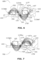
- FIG. 7 is an illustration of the embodiment of FIG. 1 showing a second active state when a finger that depresses the cantilever trigger mechanism is released from the offset cantilever trigger mechanism and the central magnet is free to rotate and mechanically oscillate to move and thus further causing the interactive attractive magnet fields between the central magnet and the two sets of inline lateral directive (counter emf reducing) magnets to distort away from an equilibrium state; and during this period the damped sinusoidal voltage waveform, of substantial time duration, is produced at the coil terminals.
- FIG. 8 is a typical damped sinewave voltage output waveform showing peak-to-peak voltage and the minimum acceptable operational voltage levels (e.g. 1.8 to 3.3 volts) for micro-transmitter chips currently in the marketplace.
- FIG. 9 is a magnetic field concentration of a prior art embodiment using a uniform horizontal inline column arrangement of a plurality of magnets, all poled in the same direction in a horizontal plane and a plurality of those column arrangements in a plurality of rows; and in a special case of a three by two column-row instance there is a centred single rotatable magnet along its horizontal axis; where the rotatable magnet is poled in a moment of time in one direction through a complete possible rotation.
- FIG. 10 is a magnetic field concentration of a novel magnet arrangement according to an embodiment of the present invention, that in contrast to FIG. 9 of prior art is a uniform horizontal inline column arrangement of a plurality of magnets, where the centre magnet is pole in an opposite direction to the remaining other member magnets, in a horizontal plane and a plurality of those column arrangements in a plurality of rows; and in a special case of a three by two column-row instance there is a centred single rotatable magnet along its horizontal axis; where the rotatable magnet is poled in a moment of time in one direction through a complete possible rotation.
- FIG. 11 is a magnetic field concentration of prior art (e.g. FIG. 9 ) using a uniform horizontal inline column arrangement of a plurality of magnets, all poled in the same direction in a horizontal plane and a plurality of those column arrangements in a plurality of rows; and in a special case of a three by two column-row instance there is a centred single rotatable magnet along its horizontal axis; where the rotatable magnet is poled in a moment of time in a direction opposite to that of FIG. 9 through a complete possible rotation.
- FIG. 12 is a magnetic field concentration of a novel counter emf reducing magnet arrangement embodiment according to the present invention, that in contrast to FIG. 11 of prior art is a uniform horizontal inline column arrangement of a plurality of magnets, where the centre magnet is pole in an opposite direction to the remaining other member magnets, in a horizontal plane and a plurality of those column arrangements in a plurality of rows; and in a special case of a three by two column-row instance there is a centred single rotatable magnet along its horizontal axis; where the rotatable magnet is poled in a moment of time in a direction opposite to that of FIG. 10 direction through a complete possible rotation.
- FIG. 13 shows the composite resultant magnetic fields surrounding the coil winding caused by an embodiment of the present invention of FIG. 12 affect during a maximum induced voltage segment of time.
- FIG. 14 shows the composite resultant magnetic fields surrounding the coil winding caused by an embodiment of the present invention of FIGS. 10 , 12 and/or 13 .
- FIG. 15 is a block diagram drawing of the resultant associated magnetic flux of the embodiment of FIG. 14 , during a centre group of the rotatable centre magnet and the top and bottom centred fixed disk magnets are in an attractive magnetic opposite-pole alignment.
- FIG. 16 is a block diagram drawing of the resultant associated magnetic flux of the embodiment of FIG. 14 , during a centre group of the rotatable centre magnet and the top and bottom centred fixed disk magnets are in an repulsive magnetic like-pole alignment.
- FIG. 1 shows the preferred embodiment 100 of the present invention that has an enclosure comprised of the enclosure body 101 and a movable push-button disposed element 101 p that is removed from enclosing to expose some of the major components of this embodiment.
- This exposure includes a base substrate 103 , which supports a wound coil bobbin 105 , a forked cantilever 107 comprised of bifurcated ends 117 f & 117 r (shown in FIG. 2 ), and a set of snap-on supports 119 f & 119 r (shown in FIG.
- first snap-on front side support 119 f and a second snap-on rear side support 119 r including a first snap-on front side support 119 f and a second snap-on rear side support 119 r , where they both snap-on for easy connection to the base substrate's 103 first rear support cylinder protrusion 129 r and the second front support cylinder protrusion 129 f .
- the push-button 101 p disposed section of the device enclosure 101 when it covers the remaining components of this embodiment, come in mechanical contact with the bifurcated plunger 107 and the push-button 101 p has the action of angular movement (downward and upward) to cause by mechanical induction, the bifurcated plunger 107 to trigger the operational action of clockwise rotating about the bifurcated plunger's 107 axis 163 downward, the centre magnet enclosure 108 and its enclosed centre magnet 112 (shown in FIG. 2 ) and thereafter freely releasing the centre magnet enclosure 108 and its magnet 112 to rotate about its axis 161 backwards in anti-clockwise rotation.
- the base substrate 103 has two sets of blind rectangular inline holes 113 a,b,c and 113 d,e,f (shown in this figure and in FIG. 2 complete) disposed within the structures 111 L & 111 R on opposite sides of the coil bobbin 105 with winding 104 (shown in FIG. 2 A ) that in addition act as a support for the coil bobbin 105 .
- the base substrate also has an enclosure 109 where the centre rotational magnet 112 and its enclosure 108 (shown in FIG. 2 and FIG. 2 A ) are seated and free to rotate and is held in place by magnet support base 110 and its two protrusions 130 f & 130 r (note: front protrusion 130 f is shown in FIG.
- the front protrusion 130 f and the rear protrusion 130 r support the axles of the magnet 112 and its enclosure 108 that allows for rotation with minimum friction since the entire substrate 103 would be made of Nylon with 30% glass and the enclosure segment 109 would be made of Delrin or some equivalent low coefficient of friction material.
- FIG. 2 is an exploded view 200 showing the present invention's preferred embodiment identifying all of the components that make up the generator without showing the cover that is shown in FIG. 1 .
- the coil bobbin 105 is designed with a built-in (moulded-in) attachment 105 a with a disposed centre through hole 106 ; and two opposite break-off tabs 106 a & 106 b ; where there is a first break-off tab 106 a , and a second break-off tab 106 b on the opposite end of the attachment 106 , whose purpose (in the production coil winding phase) is to allow the coil bobbin 105 to be mounted on a coil winding machine and then post-winding, the attachment 105 a is easily snapped off in production.
- These plurality of small disk type magnet sets are axially poled and act as counter emf reducing magnets directing the combined magnet fields (shown in FIGS. 7 , 8 , & 9 ) through the coil winding 104 wound around the coil bobbin 105 ; and the first intermediate magnetic field 701 (shown in FIG. 5 is in its equilibrium non-trigger state) between plurality magnets 113 a,b , c and the centre rotating magnet 112 passes through the first half of coil 105 and its winding 104 ; and the second intermediate magnetic field 703 (shown in FIG.
- the centre drive magnet 112 is disposed (fixed) within its axially rotatable enclosure 108 and is free to rotate about its dual inline axles 115 F & 115 r (about the axles 115 F & 115 r axis 161 ) as the complete drive magnet assembly 112 & 108 ; and this assembly 112 & 108 is disposed within the magnet drive housing 109 that is a section of the base substrate 103 .
- the magnet drive assembly 112 & 108 is supported by its axles 115 f & 115 r ; and respectively free to rotate about its axis 161 between the two protrusions 130 f & 130 r (that are tangent along the plane of the support cover 108 ) and the open slots 133 f & 133 r ; and when the support cover 108 is inserted and fixed in place by insertion of the two protrusions 130 f & 130 r into the open slots 133 f & 133 r the free space created by this action acts as a complete rotatable magnet axle drive assembly 112 & 108 that upon triggering has bi-directional damped rotating action resulting in the damped oscillatory voltage waveform.
- FIG. 2 A is a “top looking down” exploded perspective drawing of the preferred embodiment of this invention showing all components for a clear understanding of the novelty of few parts required for comprising this invention.
- the base substrate 103 that has as part of its monolithic design, a centre magnet section 109 for holding in place the centre drive magnet 112 disposed within the rotatable magnet enclosure 108 (about its axis 161 ).
- a centre magnet section 109 for holding in place the centre drive magnet 112 disposed within the rotatable magnet enclosure 108 (about its axis 161 ).
- FIG. 2 A also shows the bifurcated trigger plunger 107 with its features of bifurcated protrusions, a first rear protrusion 117 f and a second front protrusion 117 r , and when the bifurcated trigger plunger 107 is snapped onto the dual axle protrusions 129 r & 129 f the bifurcated trigger plunger 107 is free to rotate about the dual axles 129 r & 129 f (about their common axis 163 ).
- the bifurcated protrusions 117 r & 117 f mechanically strike (hit) the two separate inline tri-finger (tri-fingered for strength) axle tabs 132 f & 132 r causing clockwise rotation on the down-stroke that causes a first polarity induced voltage produced and when the bifurcated trigger plunger springs back this causes an anti-clockwise rotation that causes a second polarity (opposite to the first down-stroke polarity) going induced voltage; and in both instances an induced AC (alternating current) voltage is produced (See FIG. 8 ).
- FIG. 2 B is a “bottom looking up” exploded perspective drawing of the preferred embodiment of this invention showing all components for a clear understanding of the novelty of few parts required for comprising this invention and it further illustrates several feature shown from the under sections therein, where the bottom support cover 108 is inserted flush with the monolithic base substrate's 103 centre magnet monolithic base section enclosure 109 and fits into the two opposite slots 133 f & 133 r of the centre magnet monolithic section enclosure 109 that acts as the axle support assembly for the centre magnet axially rotatable enclosure 108 that contains the centre magnet 112 .
- Another feature of this embodiment that is a substantial aid during production is to have the coil bobbin designed with a keyed insert slotted arrangement, where there are four uniform spaced in a rectangular paradigm position arrangement that contains four protrusions of a first protrusion that is a key 121 p and three identical cylinder protrusions 123 p , 125 p , 127 p that fit into identical through holes of a first key hole 121 and three identical through holes 123 , 125 , 127 . for insertion and lock-in.
- a method of coil production with automatic coil winding machines is to allow easy quick mounting of the coil bobbin 105 on a coil winding machine and to do a fast winding procedure for a finished winding 104 .
- This method can be accomplished easily if the coil bobbin 105 has a break-off rectangular attachment 105 a at the centre of the coil bobbin 105 and at the centre of the break-off attachment 105 a is a centred through hole 106 for insertion on a bobbin rod of a coil winding machine.
- FIG. 2 C is an exploded component view comprising the two separate plurality sets of focus directive magnets 141 a, b, c and 141 d, e, f that are inserted and fixed into the open blind hole slots 113 a, b, c and 113 d, e, f respectively and fixed within. Also in FIG. 2 C is the centre magnet rotatable enclosure with its blind rectangular hole 108 s that holds fixed within the centre magnet 112 (shown in FIG.
- the centre magnet 112 is disposed and fixed within the centre magnet slotted blind rectangular hole 108 s and the comprised magnet 112 and its enclosure 108 are pivotal about its axis 161 .
- the two axles 115 f & 115 r are contiguous with the enclosure 108 support member's 108 two separate tangent (to the plane surface of the support member 108 ) protrusions.
- the trigger receiver tabs 132 f & 132 r become contiguous with the bifurcated cantilever's (see FIG. 3 and FIG. 4 and FIG. 5 , FIG. 6 , & FIG. 7 ) finger tabs 117 f & 117 r respectively.
- FIG. 3 illustration 300 shows the present invention's preferred embodiment as a side cutaway view, in its static equilibrium state before a trigger is caused by the urging of the spring 513 by the push-lever 101 p that experienced the urging of a finger 501 or other mechanical force source.
- FIG. 4 illustration 400 shows the present invention's preferred embodiment as a side cutaway view, during the “turn ON action procedure” of a human finger 501 or an external trigger caused by the urging of the spring 513 by the push-lever 101 p that experiences the urging of a finger 501 or other mechanical force source.
- the “turn ON action procedure” produces a “Rube Goldberg type action-sequential” triggering by its members that are utilized to produce electrical power by action of pressing-in, the push-button 101 p that is part of the device enclosure 101 , and the push-button tangent extension 505 of the push-button 101 p then comes in instant contact with the dual fork cantilever 107 and whose dual fork fingers 117 f & 117 r that are a sub-member of the bifurcated cantilever trigger member 107 .
- the bifurcated cantilever trigger member 107 urges the spring 513 to produce a forward force downward and the resultant compression of the spring 513 stores potential energy that is created during this process. Then by the instant finger 501 release upward of the bifurcated cantilever trigger member 107 , action and reaction that is created causes the dual fork fingers 117 f & 117 r to instantly create a contiguous connection between the dual fork tab fingers 117 f & 117 r , and the upper tabs 132 f & 132 r as respective sub-members of the inline axles 115 f & 115 r that are part of the centre magnet 112 contained in its rotatable enclosure 108 and remain in a damped oscillatory alternating electrical energy producing state ( FIG. 8 ) until the frictional forces diminish to a rotational stoppage of the centre magnet 112 in its rotatable enclosure 108 .
- FIG. 5 is an illustration 500 of a partial cutaway view of the preferred embodiment 500 that illustrates the rest “non-trigger” state of the invention's encompassing attractive magnetic field 701 and 703 and purposely not showing (for simplicity) the complete magnetic circuitous path that travels all through the invention's embodiment but is shown for understanding in FIG. 5 A .
- FIG. 5 A is a simplified illustration 500 -A showing a complete and circuitous effective magnetic field of the invention's preferred embodiment 500 -A where the surrounding magnetic field 700 extends from the outside pole of the left focus magnet inline array 113 abc to the right focus magnet inline array 113 def , thus making a closed circuitous path for the magnetic lines of force.
- the entire inner 701 & 703 and outer overhead 702 magnetic circuit path changes (see FIG. 6 & FIG. 7 ) its field flux intensity through the coil 105 during the damped cyclic oscillatory bi-rotation of the centre inline axles centre magnet 112 rotatable enclosure 108 (shown in FIG. 2 )
- the angular sequential induced voltage producing operation of the preferred embodiment and influence of the changing magnetic field 705 & 707 is shown in the illustration 600 in FIG. 6 during an instant of downward depression, by the urging of a finger or some other external intentional mechanical energy source (shown in FIG. 3 ), on the bifurcated cantilever 107 that simultaneously rotates downward 107 d on its axis of rotation 163 .
- the two fork tab fingers 117 f & 117 r of the bifurcated cantilever 107 comes in instant contiguous contact with the axle tabs 132 f & 132 r (note: with the cutaway views, only the front inline axle tab 132 f is shown and the rear inline axle tab 132 r is not shown but works instantly in parallel inline sequence) causing the centre magnet 112 fitted within its rotatable enclosure 108 to rotate from 0 degrees up to 90 degrees clockwise on its axis 161 (this effectively and simultaneously causes the centre magnet 112 to rotate to a new angular position 112 cw ) and as the forked finger tabs 117 f & 117 r disconnect from a contiguous state with the rotatable magnet enclosure's 108 finger tabs 132
- the centre magnet 112 in its rotatable enclosure is free to oscillate; and this action creates the surrounding encompassing magnetic fields 701 & 703 to change periodically in a sinusoidal movement 705 , 707 , 709 , 711 .
- This periodic clockwise rotation of the centre magnet 112 simultaneously in union within its enclosure 108 causes a changing left magnetic field 701 / 705 that firstly passes up through the left side of the coil 105 and simultaneously the changing right magnetic field 703 / 707 secondly passes down through the right side of the coil 105 ; thus producing an instant first half sinusoidal duty cycle of induced EMF (voltage) that is felt at the coil terminals ( 102 ti & 102 t 2 shown in FIG. 1 ).
- both members are noncontiguous and the centre magnet 112 in its rotatable enclosure 108 and its contained centre magnet 112 is free to oscillate between a diminishing repeating travel angle range of 0° to +900 ( 112 cw ), to 0° to ⁇ 90° ( 112 acw ), back to 0° with decreased terminal EMF (voltage) following a mathematical path conforming to the damping values of X e ( 173 , as shown in FIG. 8 ).
- This first cyclic duration of the downward depression phase gives way to the second cyclic duration when the “contiguous-to-noncontiguous” finger 501 to bifurcated cantilever plunger 107 connection is forced back upward by the stored potential energy in the spring 513 , being converted to upward (spring expanding) kinetic energy (explained in FIG. 7 )
- FIG. 7 illustration 700 represents the duration when the bifurcated cantilever springs back 107 u to its non-triggered rest position 107 .
- This spring 513 produced forced action causes the bifurcated tabs 117 f & 117 r to endure a contiguous connection between the enclosure 108 finger tabs 175 f & 175 r that causes magnet 112 in its rotatable enclosure 108 to rotate anti-clockwise 112 acw to +900 and when the dual fingered cantilever 107 travels to its non-triggered rest position, the centre magnet enclosure with its enclosed centre magnet 112 are free to oscillate between a diminishing repeating travel angle range of 0° to ⁇ 90° ( 112 acw ), to 0° to +900 ( 112 cw ), back to 0° with decreased terminal EMF (voltage) that following a mathematical path conforming to the damping values of X e ( 173 , as shown in FIG. 8 ).
- FIG. 8 is a graph 800 of a S N typical generated AC (alternating current) peak-to-peak Vp-p 165 voltage waveform 161 by the present invention over a time ⁇ t duration of 169 , firstly under a no electrical load appliance connected at the coil terminals; and second the generated AC (alternating current) peak-to-peak Vp-p 165 voltage waveform 161 affected by an electrical load appliance connected to the coil terminals.
- X e 163 for each case by friction on the invention's embodiment producing the voltage, providing and indicium of the reduction in power output increase as the electrical load increases by nature.
- FIG. 9 is a top comparison illustration 900 of the prior art 01 pa that depicts a first plurality arrangement of magnets and in this referred to exemplary embodiment there are two separated sets of three inline disk magnets with all of their magnetic poles aligned in the same and parallel direction.
- the first set consists of a first inline magnet 011 with South pole up (along a line in the plane of the drawing, i.e.
- FIG. 9 Also in the illustration of FIG. 9 are the prior art's magnetic contour plotted regional zones where all of the magnetic flux regions are attractive showing relative magnetic flux densities; there are four marginal attractive magnetic flux density zonal regions r 1 ′, r 3 ′, r 4 ′, & r 6 ′ that pass through the coil winding 01 C due to the top row magnets 011 , 012 , 014 all being of the same attractive magnetic pole alignment; and there are two marginal magnetic flux density attractive zonal regions r 2 ′ & r 5 ′ all being of the same attractive magnetic pole alignment.
- FIG. 10 shows an illustration 1000 for novel and advantageous N features of the present invention's magnetic array over that of the referenced prior art 01 pa in FIG. 9 .
- a first set consisting of a first inline magnet 141 a with its South pole up (in paper) and North pole down (in paper), a closely separated all important centre inline second magnet 141 b with its North pole up (in paper) and with its South pole down (in paper), and a third closely separated inline magnet 141 c with its South pole up (in paper) and its North pole down (in paper); and a second set of a first inline magnet 141 d with South pole up (in paper) and North pole down (in paper), a closely separated all important centre inline second magnet 141 e with North pole up (in paper) and South pole down (in paper), and a third closely separated inline magnet 141 f with its South pole up (in paper) and with its North pole down (in paper).
- FIG. 10 represents the centre magnet 112 in a moment during cyclic rotation about its axis A 2 when its South pole is up (in paper) and its North pole is down (in paper).
- This stopped moment in time is when the induced AC voltage sinusoidal waveform is going through its instantaneous zero time derivative value.
- the magnetic intensity contour plot shows a densely concentrated magnetically attractive zonal distribution with strong magnetic flux lines of force density r 1 , r 3 , r 4 , & r 6 passing through the area of the coil winding 104 and moderate repulsive magnetic flux lines of force density r 2 &r 5 passing through the coil winding 104 , and that would conclude the “Magnet Array” does offer and teach, by empirical evidence, a novel optimized design feature for maximum power generation from the present invention generator over that of the cited prior art 01 pa.
- FIG. 10 Also in the illustration of FIG. 10 are the prior art's magnetic contour plotted regional zones at magnetic equilibrium (pre-S ⁇ N triggering) where there are attractive and repulsive magnetic flux regions showing N S relative magnetic flux densities: there are S ⁇ N; four separate proximal-distal substantially attractive angular magnetic flux density zonal regions r 1 , r 3 , r 4 , & r 6 , attractive in respect to the centre rotatable magnet 112 in this moment in time of N magnetic equilibrium and the flux line contours, at a cosine angle vector N ⁇ S value, pass substantially strong through the coil winding 104 due to the two separate top row end magnets 141 a , & 141 c being of the same attractive magnetic pole alignment, but the centre top row magnet 141 b is like-poled; and is repulsive to the centre magnet 112 ; and there are two separate inline marginal magnetic flux density repulsive zonal regions r 2 & r 5 all being of the same repulsive
- this inter coupling reduces significantly the number of repelling flux in the region of the centre zone region r 2 ; and provides less repelling flux, which allows for more attractive zones r 1 & r 3 and r 4 & r 6 , which in turn when triggered, the generator bi-directional rotational operation will rotate with increased velocity and will generate a longer time duration damped sinusoidal voltage waveform compared to prior art. All of these dynamically changing coupling factors allow for an improved method of generator operational output.
- FIG. 11 is a top comparison illustration 1100 of the prior art 01 pa that depicts a first plurality arrangement of magnets and in this referred to exemplary embodiment there are two separated sets of three inline disk magnets with all of their magnetic poles aligned in the same and parallel direction.
- the first set consists of a first inline magnet 011 with South pole up (in paper) and North pole down (in paper), a closely separated centre inline second magnet 012 with South pole up (in paper) and North pole down (in paper), and a third closely separated inline magnet 014 ; and a second set of a first inline magnet 016 with South pole up (in paper) and North pole down (in paper), a closely separated centre inline second magnet 018 with South pole up (in paper) and North pole down (in paper), and a third closely separated inline magnet 010 .
- FIG. 11 represents the centre magnet 020 in a moment during cyclic rotation about its axis A 1 when its North pole is up (in paper) and its South pole is down (in paper).
- the magnetic lines of force for these comparisons was done by using a two dimensional visual software programme for calculating and displaying magnetic lines of force.
- the magnetic intensity contour plot shows a uniform distribution without any strong lines of force density with the area of the coil winding, and that would conclude an non-optimized design feature that would “not” offer any optimized maximum power generation from the generator.
- FIG. 11 Also in the illustration of FIG. 11 are the prior art's magnetic contour plotted regional zones where magnetic regions are all repulsive showing relative magnetic flux densities; there are four concentrated repulsive magnetic flux density zonal regions r 1 ′, r 3 ′, r 4 ′, & r 6 ′ that pass away from the coil winding 01 C due to the top row magnets 011 , 012 , 014 all being of the same magnetic pole alignment S ⁇ N repulsive to the rotatable centre magnet 020 in a repulsive Ns moment in time; and there are two marginal magnetic flux density repulsive zonal regions r 2 ′ & r 5 ′ all being of the same magnetic repulsive pole S ⁇ N alignment.
- FIG. 12 shows an illustration 1200 for novel and advantageous features of one embodiment of the present invention's magnetic array over that of the referenced prior art Olpa in FIG. 9 .
- a first set consisting of a first inline magnet 141 a with its South pole up (in paper) and North pole down (in paper), a closely separated all important centre inline second magnet 141 b with its North pole up (in paper) and with its South pole down (in paper), and a third closely separated inline magnet 141 c with its South pole up (in paper) and its North pole down (in paper); and a second set of a first inline magnet 141 d with South pole up (in paper) and North pole down (in paper), a closely separated all important centre inline second magnet 141 e with North pole up (in paper) and South pole down (in paper), and a third closely separated inline magnet 141 f with its South pole up (in paper) and with its North pole down (in paper).
- FIG. 10 represents the centre magnet 112 in a moment during cyclic rotation about its axis A 2 when its South pole is up (in paper) and its North pole is down (in paper).
- This stopped moment in time is when the induced AC voltage sinusoidal waveform is going through its instantaneous maximum time derivative value.
- the magnetic intensity contour plot shows a densely concentrated distribution with strong lines of force density within the area of the coil winding, and that would conclude the embodiment(s) of the present invention does offer and teach, by empirical evidence, an novel optimized design feature for maximum power generation from the present invention generator over that of the cited prior art 01 pa.
- FIG. 12 Also in the illustration of FIG. 12 are the prior art's magnetic contour plotted regional zones at magnetic equilibrium (pre-triggering) where there are attractive and repulsive magnetic flux regions showing relative magnetic flux densities; there are four separate proximal-distal substantially moderate repulsive angular magnetic flux density zonal regions r 1 , r 3 , r 4 , & r 6 , N s repulsive in respect to the centre rotatable magnet 112 in N ⁇ S this moment in time of magnetic equilibrium (pre-triggering), and the flux lines at a cosine angle vector value, repel substantially moderate away from the coil winding 104 due to the two separate top row end magnets 141 a , & 141 c being of the same repulsive magnetic pole alignment N ⁇ S, but the centre top row magnet 141 b and the centre bottom row magnet 141 e are both opposite-poled S ⁇ N and they are proximal attractive to the centre rotational magnet 112 ; and there are two separate inline marginal magnetic flux
- this inter coupling reduces significantly the number of changing repelling flux in the region of the top row first zone region r 1 , and third zone region r 3 plus bottom fourth zone region r 4 and sixth zone region r 6 ; and provides less repelling flux, which allows for more attractive magnetic flux zones' r 2 & r 5 desired rotational torque, when triggered, the generator bi-directional rotational operation will rotate with increased velocity and will generate a longer time duration damped sinusoidal voltage waveform compared to prior art. All of these dynamically changing coupling factors allow for an improved method of generator operational output.
- FIG. 13 and FIG. 14 are illustrations of an embodiment of the present invention having a plurality of rows and columns of magnets including a plurality of inline magnets set up as a matrix, and for this present invention, there are rare earth disk magnets arranged in a three column by two row array (matrix), where each column member magnet is separated proximal from each other and each row of three member magnets is separated distal from each other; for this present invention's embodiment, and what distinguishes and renders novel is in each row is the magnetic pole alignment of each member magnet to each other.
- the arrangement is such that their respective “up & down” magnetic pole circuitous alignment exists so that there is a first set of a 1 st member 141 a S ⁇ N with (poled S facing up), a 2 nd member 141 b with N S (poled N facing up in paper), and a 3 rd member 141 c S ⁇ N with (poled S facing up in paper) and they are all separated on one side proximal of a coil bobbin 105 with its wire winding 104 and on a side opposite the coil bobbin with its wire winding is a disposed second set of a 1st member 141 d with S ⁇ N (poled s facing up in paper), a 2 nd member 141 e N ⁇ S with (poled N facing up in paper), and a 3 rd member 141 f with S ⁇ N (poled S facing up in paper); and disposed centred within the coil bobbin 105 , is a rotatable about its axis, magnet.
- first changing differential function magnetic field region between the 2 nd magnet member 141 b (centre position) of the first row and a first width side of the rotatable centre magnet 112 disposed and free to rotate about its axis of rotation and there is disposed a second changing differential function magnetic field region between the 2nd magnet member 141 e (centre position) of the second row and a second opposite width side of the rotatable centre magnet 112 disposed and free to rotate about its axis of rotation.
- FIG. 13 shows the “complex-pole produced” magnetic flux field distribution during a time when the instantaneous rotating of the centre rotatable magnet 112 is rotating about its axis A 2 and the rotatable magnet 112 is in a proximal and perpendicular to the axis of rotation A 2 “attractive-opposite-pole magnetic alignment” with the first row centre magnet member 141 b , and the rotatable magnet 112 is in a proximal and perpendicular to the axis of rotation A 2 “attractive opposite pole magnetic alignment” with the second row centre magnet member 141 e ; and in this instantaneous time the induced output voltage of the generator is going through the maximum induced generator output voltage duration.
- FIG. 14 shows the “complex-pole produced” magnetic flux field distribution during a time when the instantaneous rotating of the centre rotatable magnet 112 is rotating about its axis A 2 and the rotatable magnet 112 is in a “repelling-like-pole magnetic alignment” with the first row centre magnet member 141 b , and the rotatable magnet 112 is in a proximal and perpendicular to the axis of rotation A 2 “repulsive opposite pole magnetic alignment” with the second row centre magnet member 141 e ; and in this instantaneous time the induced output voltage of the generator is going through the minimum induced generator output voltage duration.
- FIG. 15 is a block diagram DA 15 of the “Magnet Array,” which is a novel matrix of magnets in a two row three column, with a centred rotatable magnet and showing the resultant vectors F 1 , F 2 , F 3 , F 4 , F 5 , & F 6 for the magnetic flux lines of force in the present invention with the centre rotatable magnet 112 magnetically interacting with the resultant magnetic flux.
- Magnetic Array is a block diagram DA 15 of the “Magnet Array,” which is a novel matrix of magnets in a two row three column, with a centred rotatable magnet and showing the resultant vectors F 1 , F 2 , F 3 , F 4 , F 5 , & F 6 for the magnetic flux lines of force in the present invention with the centre rotatable magnet 112 magnetically interacting with the resultant magnetic flux.
- FIG. 15 also shows the magnetic flux field intensity between 1st row centre magnet 141 b and the magnetic flux field intensity of centre rotatable magnet 112 separated by proximal distance d 1 and where the attractive force F 2 varies to the inverse cube of the distance d 1 .
- FIG. 16 is a block diagram DA 16 of an embodiment of present invention having a novel matrix of magnets in a two row three column, with a centred rotatable magnet and showing the resultant vectors F 1 , F 2 , F 3 , F 4 , F 5 , & F 6 for the magnetic flux lines of force in the present invention with the centre rotatable magnet 112 magnetically interacting with the resultant magnetic flux.
- FIG. 16 also shows the magnetic flux field intensity between 1st row centre magnet 141 b and the magnetic flux field intensity of centre rotatable magnet 112 separated by proximal distance d 1 and where the repulsive force F 2 varies to the inverse cube of the distance d 1 .
- the present invention includes additional magnets in each row disposed according to the teaching of the present invention, and lesser or greater number of trigger receiver tabs and corresponding finger tabs with corresponding modifications to related or surrounding structures to accommodate such additional magnets or tabs. Further modifications and/or substitutions by one of ordinary skill in the art according to the present invention is considered to be part of the present invention.
Landscapes
- Engineering & Computer Science (AREA)
- Power Engineering (AREA)
- Combustion & Propulsion (AREA)
- Chemical & Material Sciences (AREA)
- General Engineering & Computer Science (AREA)
- Mechanical Engineering (AREA)
- Health & Medical Sciences (AREA)
- Toxicology (AREA)
- Physics & Mathematics (AREA)
- Electromagnetism (AREA)
- Permanent Magnet Type Synchronous Machine (AREA)
- Reciprocating, Oscillating Or Vibrating Motors (AREA)
- Electromagnets (AREA)
Abstract
Description
V=emf−Ir (Eq. 1)
where r is the internal resistance and I is the current flowing at the time of the measurement.
P=V 2 /R (induced voltage squared divided by the load resistance) and now relating to Faraday's Law; (eq. 2)
P=(Nd(B·A)/dt)/R I ∝N 2 /R I (eq. 3)
∴N∝1/r Then R c =R coil =pI∝(1/r 2)(πdN)∝(1/r 3) (eq. 4)
Power∝N 2 /R c∝(1/r)2(1/r)3 ∝r (eq. 5)
V coil =Nd(B·A)/dt∝1/r This is a crucial mathematical balancing act. (eq. 6)
-
- [1] The area around the magnetic field where the poles and the moving charge experience the force of attraction and repulsion is called a magnetic field. Whereas, the magnetic flux shows the quantities of the magnetic lines of force passes through it.
- [2] The magnetic field is expressed as the product of the magnetic strength and the direction of the moving F=qvB charges,
-
- [3] The SI unit of the magnetic field is the Tesla whereas the SI unit of magnetic flux is the Weber.
- [4] The magnetic field only depends on the magnet which generates it whereas the magnetic flux depends on the magnetic strength and area.
Claims (20)
Priority Applications (1)
| Application Number | Priority Date | Filing Date | Title |
|---|---|---|---|
| US17/839,473 US12062965B2 (en) | 2019-07-20 | 2022-06-13 | Offset triggered cantilever actuated generator |
Applications Claiming Priority (3)
| Application Number | Priority Date | Filing Date | Title |
|---|---|---|---|
| US201962876621P | 2019-07-20 | 2019-07-20 | |
| US16/675,401 US11368079B2 (en) | 2019-11-06 | 2019-11-06 | Offset triggered cantilever actuated generator |
| US17/839,473 US12062965B2 (en) | 2019-07-20 | 2022-06-13 | Offset triggered cantilever actuated generator |
Related Parent Applications (1)
| Application Number | Title | Priority Date | Filing Date |
|---|---|---|---|
| US16/675,401 Continuation US11368079B2 (en) | 2019-07-20 | 2019-11-06 | Offset triggered cantilever actuated generator |
Publications (2)
| Publication Number | Publication Date |
|---|---|
| US20230137951A1 US20230137951A1 (en) | 2023-05-04 |
| US12062965B2 true US12062965B2 (en) | 2024-08-13 |
Family
ID=75687931
Family Applications (2)
| Application Number | Title | Priority Date | Filing Date |
|---|---|---|---|
| US16/675,401 Active 2040-04-17 US11368079B2 (en) | 2019-07-20 | 2019-11-06 | Offset triggered cantilever actuated generator |
| US17/839,473 Active 2039-12-10 US12062965B2 (en) | 2019-07-20 | 2022-06-13 | Offset triggered cantilever actuated generator |
Family Applications Before (1)
| Application Number | Title | Priority Date | Filing Date |
|---|---|---|---|
| US16/675,401 Active 2040-04-17 US11368079B2 (en) | 2019-07-20 | 2019-11-06 | Offset triggered cantilever actuated generator |
Country Status (1)
| Country | Link |
|---|---|
| US (2) | US11368079B2 (en) |
Cited By (1)
| Publication number | Priority date | Publication date | Assignee | Title |
|---|---|---|---|---|
| US12505969B2 (en) | 2017-10-30 | 2025-12-23 | Wepower Technologies Llc | Magnetic momentum transfer generator |
Families Citing this family (12)
| Publication number | Priority date | Publication date | Assignee | Title |
|---|---|---|---|---|
| US9343931B2 (en) | 2012-04-06 | 2016-05-17 | David Deak | Electrical generator with rotational gaussian surface magnet and stationary coil |
| US11368079B2 (en) * | 2019-11-06 | 2022-06-21 | David Deak, SR. | Offset triggered cantilever actuated generator |
| US11509209B2 (en) * | 2019-11-08 | 2022-11-22 | Giovanni De Gasperis | Generator using permanent magnets |
| CN115053437A (en) | 2019-11-21 | 2022-09-13 | 威能科技有限责任公司 | Tangentially actuated magnetic flux transfer generator |
| JP7533871B2 (en) * | 2020-01-15 | 2024-08-14 | ミネベアミツミ株式会社 | Vibration actuator and electronic device |
| US20210257896A1 (en) * | 2020-02-17 | 2021-08-19 | Dan Haronian | Movement and Vibration energy harvesting |
| JP7504624B2 (en) * | 2020-02-28 | 2024-06-24 | キヤノン株式会社 | Power generating element and device using the power generating element |
| JP2024508580A (en) * | 2021-01-25 | 2024-02-28 | ピーエス・オーディオ・デザイン・オイ | Methods and configurations for generating haptic effects in user devices |
| JP7478694B2 (en) * | 2021-03-08 | 2024-05-07 | 株式会社日立製作所 | Rotating magnetic field generator, magnetic refrigeration device, and hydrogen liquefaction device |
| US12278537B2 (en) * | 2021-05-05 | 2025-04-15 | Enervibe Ltd. | Electromagnetic vibration and energy harvester |
| US11936269B2 (en) * | 2021-09-22 | 2024-03-19 | Apple Inc. | Haptic engine based on angular resonant actuator with pivot axis and mass center that differ |
| EP4646779A1 (en) * | 2023-01-04 | 2025-11-12 | WePower Technologies LLC | Trip mechanism based energy generator for electrical energy generation |
Citations (138)
| Publication number | Priority date | Publication date | Assignee | Title |
|---|---|---|---|---|
| US1711323A (en) | 1926-06-23 | 1929-04-30 | Richard A Oglesby | Oscillating magneto |
| US2703370A (en) | 1952-07-02 | 1955-03-01 | Steensen Sverre Johan | Electric compressor or pump motor with rolling rotor |
| US3027499A (en) | 1957-10-23 | 1962-03-27 | Spoorweg Sein Ind N V | Electromagnetic system |
| US3218523A (en) | 1963-07-29 | 1965-11-16 | Benson Hector Eugene | Electromagnetic device having a permanent magnet armature |
| US3315104A (en) | 1964-04-16 | 1967-04-18 | Square D Co | Magnetic impulse generator |
| US3348080A (en) | 1965-06-07 | 1967-10-17 | Gen Dynamics Corp | Impulse generator |
| US3398302A (en) | 1964-10-13 | 1968-08-20 | Essex Wire Corp | Electrical impulse generator |
| US3500082A (en) | 1967-08-15 | 1970-03-10 | Manuel J Tolegian | Drive unit for flexible shafts |
| US3621419A (en) | 1970-02-19 | 1971-11-16 | Leach Corp | Polarized latch relay |
| US3671777A (en) | 1968-03-22 | 1972-06-20 | Mesur Matic Electronics Corp | Fast rise time pulse generator |
| US3673999A (en) | 1970-08-24 | 1972-07-04 | Braun Anton | Electrical apparatus for initiating combustion in free piston engines |
| US3895244A (en) | 1973-12-28 | 1975-07-15 | Norse Systems Inc | Encapsulated electromagnetic generator |
| US3984707A (en) | 1973-07-13 | 1976-10-05 | Mcclintock Richard D | Spring return linear signal generator |
| US4187452A (en) | 1975-08-27 | 1980-02-05 | International Business Machines Corporation | Electromechanical torsional oscillator with resonant frequency and amplitude control |
| US4257010A (en) | 1976-01-28 | 1981-03-17 | Rederiaktiebolaget Nordstjernan | Method and apparatus for sensing and maintaining oscillations in an oscillating system |
| US4260901A (en) | 1979-02-26 | 1981-04-07 | Woodbridge David D | Wave operated electrical generation system |
| US4315197A (en) | 1980-02-07 | 1982-02-09 | The United States Of America As Represented By The Administrator Of The National Aeronautics And Space Administration | Linear magnetic motor/generator |
| US4363980A (en) | 1979-06-05 | 1982-12-14 | Polaroid Corporation | Linear motor |
| US4412355A (en) | 1981-10-14 | 1983-10-25 | Hughes Aircraft Company | Push-button operated electrical power source for an optical communication link |
| DE3218181A1 (en) | 1982-05-14 | 1983-11-17 | Kuno Moser GmbH, Fabrik für Feinmechanik und Elektrotechnik, 7731 Unterkirnach | Oscillating armature drive and a method for operating an oscillating armature drive |
| US4471353A (en) | 1981-10-14 | 1984-09-11 | Hughes Aircraft Company | Push-button switch for an electrical power source |
| US4521712A (en) | 1983-11-25 | 1985-06-04 | United Technologies Automotive, Inc. | Pressure sensitive piezoelectric signal generator assembly |
| US4703293A (en) | 1985-03-25 | 1987-10-27 | Matsushita Electric Works, Ltd. | Polarized electromagnetic actuator device |
| US4752706A (en) | 1983-09-22 | 1988-06-21 | Meszaros Leslie G | Rolling magnetic friction electricity generator |
| US4855699A (en) | 1988-03-11 | 1989-08-08 | Teledyne Microwave | Self-cutoff for latching coaxial switches |
| US4866321A (en) | 1985-03-26 | 1989-09-12 | William C. Lamb | Brushless electrical machine for use as motor or generator |
| US4870306A (en) | 1981-10-08 | 1989-09-26 | Polaroid Corporation | Method and apparatus for precisely moving a motor armature |
| US5053659A (en) | 1990-10-05 | 1991-10-01 | Denson Parker | Centrifugal force magnetic field variator |
| US5183056A (en) | 1989-10-20 | 1993-02-02 | Siemens Aktiengesellschaft | Inductive motion sensor |
| US5204570A (en) | 1991-09-09 | 1993-04-20 | Gerfast Sten R | Spheroidal machine |
| US5275141A (en) | 1991-05-31 | 1994-01-04 | Asmo, Co., Ltd. | Actuator |
| US5499013A (en) | 1992-03-13 | 1996-03-12 | Konotchick; John A. | Pulse power generator |
| WO1996028873A1 (en) | 1995-03-13 | 1996-09-19 | Ashley & Rock Limited | Electric switch |
| US5608366A (en) | 1994-03-04 | 1997-03-04 | Omron Corporation | Electronmagnetic device |
| US5708406A (en) | 1995-03-20 | 1998-01-13 | Asmo Co. Ltd. | Rotary actuator |
| US5808381A (en) | 1994-08-09 | 1998-09-15 | Hitachi Metals, Ltd. | Linear motor |
| US5872407A (en) | 1995-03-31 | 1999-02-16 | Minolta Co., Ltd. | Linear motor |
| JPH11264368A (en) | 1998-03-17 | 1999-09-28 | Yukio Hirata | Double-rack four-shaft magnet engine |
| EP0948018A2 (en) | 1998-03-31 | 1999-10-06 | KMW Co., Ltd. | Switch with a rocker, which has an affixed magnet |
| US5990583A (en) | 1996-05-21 | 1999-11-23 | Minolta Co. , Ltd. | Shaft-type linear motor |
| US6069420A (en) | 1996-10-23 | 2000-05-30 | Omnific International, Ltd. | Specialized actuators driven by oscillatory transducers |
| WO2001022587A1 (en) | 1999-09-23 | 2001-03-29 | Baran Advanced Technologies (86) Ltd. | A continuous switch employing a pressure-sensitive element |
| US6259372B1 (en) | 1999-01-22 | 2001-07-10 | Eaton Corporation | Self-powered wireless transducer |
| US20010045785A1 (en) | 1998-02-10 | 2001-11-29 | Light Sciences Corporation | Contactless energy transfer apparatus |
| US6326714B1 (en) | 1999-10-27 | 2001-12-04 | Moog Inc. | Two-axis pointing motor |
| WO2002037516A2 (en) | 2000-11-06 | 2002-05-10 | Dyna Systems Gmbh | Electric switch, especially a piezo switch, with optical and/or mechanical feedback of the switching operation |
| US20020070712A1 (en) | 2000-12-13 | 2002-06-13 | Arul Senthil G. | Hand-held remote-control device with high-capacitance power supply |
| US20020130561A1 (en) | 2001-03-18 | 2002-09-19 | Temesvary Viktoria A. | Moving coil motor and implementations in MEMS based optical switches |
| US20020190610A1 (en) | 1999-12-16 | 2002-12-19 | Philippe Andre | Self-powered remote control device, electrical apparatus and installation comprising same |
| US20030025416A1 (en) | 1997-10-16 | 2003-02-06 | Sullivan Steven L. | Generators and transformers with toroidally wound stator winding |
| US20030155771A1 (en) | 2002-02-19 | 2003-08-21 | Innovative Technology Licensing, Llc | Electrical generator with ferrofluid bearings |
| US6630894B1 (en) | 2000-07-14 | 2003-10-07 | Face International Corp. | Self-powered switching device |
| US20030197433A1 (en) | 2002-04-18 | 2003-10-23 | Innovative Technology Licensing, Llc | Electrical power generation by coupled magnets |
| US6659176B2 (en) | 1996-09-27 | 2003-12-09 | Raj Mahadevaiah | Method for monitoring remediation of non aqueous phase solution |
| US6700310B2 (en) | 2000-10-13 | 2004-03-02 | Lear Corporation | Self-powered wireless switch |
| US20040051416A1 (en) | 2002-09-13 | 2004-03-18 | Honda Giken Kogyo Kabushiki Kaisha | Permanent magnet rotor |
| US6720681B2 (en) | 2001-06-05 | 2004-04-13 | Hiwin Mikrosystem Corp. | Structure and manufacturing method of a linear stepping motor |
| US6720682B2 (en) | 2001-06-14 | 2004-04-13 | Lightbay Networks Corporation | Actuator assembly for tilting a mirror or like object |
| US20040078662A1 (en) | 2002-03-07 | 2004-04-22 | Hamel Michael John | Energy harvesting for wireless sensor operation and data transmission |
| US20040124729A1 (en) | 2002-12-09 | 2004-07-01 | Long Johnny D. | Ellipsoid generator |
| US20040128781A1 (en) | 2001-03-27 | 2004-07-08 | Tomohiro Kunita | Linear oscillator and electrically driven toothbrush |
| US20040174287A1 (en) | 2002-11-21 | 2004-09-09 | Deak David G. | Self-contained switch |
| US20040222709A1 (en) | 2003-05-09 | 2004-11-11 | Hiroaki Naganuma | Electromagnetic drive device and light quantity adjustment device using the same |
| US20050006961A1 (en) | 2003-07-11 | 2005-01-13 | Kun-Tsai Shen | Manual electric generating device |
| US20050023905A1 (en) | 2003-07-31 | 2005-02-03 | Japan Servo Co., Ltd. | Toroidal-coil linear stepping motor, toroidal-coil linear reciprocating motor, cylinder compressor and cylinder pump using these motors |
| US20050168108A1 (en) | 2003-10-24 | 2005-08-04 | Face Bradbury R. | Self-powered, electronic keyed, multifunction switching system |
| US20050280316A1 (en) | 2004-06-21 | 2005-12-22 | Konica Minolta Medical & Graphic, Inc. | Linear motor and manufacturing method of linear motor |
| US7015778B2 (en) | 2002-09-05 | 2006-03-21 | Citizen Watch Co., Ltd. | Actuator device |
| US7021603B2 (en) | 1998-10-08 | 2006-04-04 | Wladyslaw Wygnaski | Electromagnetic actuator and integrated actuator and fluid flow control valve |
| US7026900B1 (en) | 2005-09-22 | 2006-04-11 | John Gregory | Magnetic motion device |
| US20060175923A1 (en) | 2003-03-06 | 2006-08-10 | Atef Abou Akar | Rotary electric machine comprising a stator and two rotors |
| US7106159B2 (en) | 2001-07-27 | 2006-09-12 | Commissariat A L'energie Atomique | Mobile magnet actuator |
| US20060234669A1 (en) | 2005-04-14 | 2006-10-19 | Rockwell Scientific Licensing Llc | Mobile device with manually operated power source |
| US20060237968A1 (en) | 2005-04-20 | 2006-10-26 | Rockwell Scientific Licensing, Llc | High efficiency power converter for energy harvesting devices |
| US20060244327A1 (en) | 2005-04-27 | 2006-11-02 | Stephen Kundel | Permanent magnet generator |
| DE102006013237A1 (en) | 2006-03-22 | 2007-10-04 | Hahn-Schickard-Gesellschaft für angewandte Forschung e.V. | Mechanical-Electric Generator |
| US20080048506A1 (en) | 2006-08-03 | 2008-02-28 | Deak David G | Electromotive device |
| US20080079319A1 (en) | 2006-09-28 | 2008-04-03 | Murata Machinery, Ltd. | Linear motor device and machine tool having the same mounted thereon |
| US7378765B2 (en) | 2004-08-09 | 2008-05-27 | Oriental Motor Co., Ltd. | Cylinder-type linear motor and moving part thereof |
| EP1936787A1 (en) | 2006-12-21 | 2008-06-25 | Saab Ab | AMPG device for generation of electrical energy from vibrations, an AMPG device assembly, and a method to optimize the generation of said electrical energy |
| US20080211435A1 (en) | 2007-03-02 | 2008-09-04 | Takahito Imagawa | Vibration generator |
| US7436082B2 (en) | 2007-01-24 | 2008-10-14 | Itt Manufacturing Enterprises, Inc. | Rocking motion charging device using faraday principle |
| WO2009015910A1 (en) | 2007-07-30 | 2009-02-05 | Col Holding Aps | A generator for a bicycle |
| US7495656B2 (en) | 2005-08-04 | 2009-02-24 | Fujitsu Component Limited | Actuator that provides tactile information |
| EP2079154A2 (en) | 2008-01-09 | 2009-07-15 | Panasonic Electric Works Europe AG | Energy converter |
| JP2009261204A (en) | 2008-04-14 | 2009-11-05 | Fukuichi Yuki | Roll-type generator |
| US7688036B2 (en) | 2006-06-26 | 2010-03-30 | Battelle Energy Alliance, Llc | System and method for storing energy |
| US7710227B2 (en) | 2003-04-07 | 2010-05-04 | Enocean Gmbh | Electromagnetic energy transducer |
| CN201490855U (en) | 2009-08-17 | 2010-05-26 | 江源 | Permanent magnet generator with multiple rotors |
| CN101895169A (en) | 2002-05-23 | 2010-11-24 | 胜沅科技股份有限公司 | Device for generating a driving force |
| US20110001381A1 (en) | 2009-07-06 | 2011-01-06 | Mcdaniel Scott L | McDaniel magnet motor |
| EP2272742A1 (en) | 2009-07-06 | 2011-01-12 | Reelight APS | Electronically controlled generator for a vehicle such as a bicycle |
| US20110140563A1 (en) | 2009-12-08 | 2011-06-16 | Commissariat a L'Energie Atomique et Aux Energies Altematives | Alternator and corresponding electric system |
| JP2011130654A (en) | 2009-11-16 | 2011-06-30 | G+ Powertec Ltd | Ac generator |
| US20110254285A1 (en) | 2010-04-15 | 2011-10-20 | Hanchett Entry Systems, Inc. | Electromagnetic Energy Harvester and a Door Latch Release Mechanism as an Energy Source for the Harvester |
| DE102010017874A1 (en) | 2010-04-21 | 2011-10-27 | Saia-Burgess Dresden Gmbh | Bistable magnetic actuator |
| US20110273052A1 (en) * | 2009-11-06 | 2011-11-10 | Electric Gorilla, LLC | Dynamoelectric device |
| US8148856B2 (en) | 2005-11-22 | 2012-04-03 | Schneider Electric Industries Sas | Stand-alone device for generating electrical energy |
| US20120104765A1 (en) | 2009-06-16 | 2012-05-03 | Universidad De Barcelona | Device for generating electric power from small movements |
| US20120133234A1 (en) | 2009-03-16 | 2012-05-31 | Pedro Da Costa Balas Ferreira | Electrical spherical generator of magnetic induction |
| US8299659B1 (en) | 2010-08-14 | 2012-10-30 | Bartol Jr Robert J | Electric power generator apparatus |
| US8330283B2 (en) | 2010-03-22 | 2012-12-11 | Ming-Sheng Lin | Underground generating device that is rolled or run over by cars so as to provide a generating effect |
| US20130033042A1 (en) | 2011-08-03 | 2013-02-07 | Energy Harvesters Llc | Method and apparatus for generating electrical energy |
| WO2013031127A1 (en) | 2011-08-29 | 2013-03-07 | パナソニック株式会社 | Electric power generating device |
| WO2013035057A2 (en) | 2011-09-06 | 2013-03-14 | Kocain Industries S.R.L. | Electric generator and method for producing electrical energy |
| US20130088018A1 (en) | 2008-02-07 | 2013-04-11 | Takaitsu Kobayashi | Linear generator having a fluid pressure cylinder structure |
| US20130093540A1 (en) | 2010-03-23 | 2013-04-18 | Zf Friedrichshafen Ag | Induction generator |
| US20130127268A1 (en) | 2010-04-30 | 2013-05-23 | Nigel Andrew Atherton | Electricity generator |
| US8514040B2 (en) | 2011-02-11 | 2013-08-20 | Clodi, L.L.C. | Bi-stable electromagnetic relay with x-drive motor |
| CN203166718U (en) | 2013-04-16 | 2013-08-28 | 慈溪宝诚知识产权服务有限公司 | Energy-saving generator |
| US8539765B2 (en) | 2007-02-19 | 2013-09-24 | Michael Miller | Engine |
| WO2013151631A1 (en) | 2012-04-06 | 2013-10-10 | David Deak | An electrical generator with rotational gaussian surface magnet and stationary coil |
| US20130342037A1 (en) | 2011-03-22 | 2013-12-26 | Sumida Corporation | Vibration-powered generator |
| US8624447B2 (en) | 2009-12-04 | 2014-01-07 | Schneider Electric Industries Sas | Electrical energy-generating device and remote control equipped with such a device |
| US8629572B1 (en) | 2012-10-29 | 2014-01-14 | Reed E. Phillips | Linear faraday induction generator for the generation of electrical power from ocean wave kinetic energy and arrangements thereof |
| US8633604B2 (en) | 2007-02-19 | 2014-01-21 | Michael Miller | Engine |
| US8729747B2 (en) | 2008-02-01 | 2014-05-20 | University Of Florida Research Foundation, Inc. | Method and apparatus for motional/vibrational energy harvesting via electromagnetic induction |
| US8773226B2 (en) | 2012-03-01 | 2014-07-08 | Johnson Electric S.A. | Driving device and relay |
| US20140246961A1 (en) | 2013-03-04 | 2014-09-04 | Stephen Smith | Energy transfer system and method |
| US20150015104A1 (en) | 2012-02-08 | 2015-01-15 | Nsk Ltd. | Actuator, stator, motor, rotational-to-linear motion conversion mechanism, and linear actuator |
| US20150091395A1 (en) | 2013-10-01 | 2015-04-02 | Jonathan David L. Spivak | Electro-mechanical Reciprocating Magnetic Piston Engine |
| US20150091479A1 (en) | 2013-10-01 | 2015-04-02 | Jonathan David L. Spivak | Electric Vehicle Propulsion System Using Magnetic Piston Engine |
| US20150279598A1 (en) | 2012-10-18 | 2015-10-01 | Panasonic Intellectual Property Management Co., Ltd. | Power generation device |
| US20150357893A1 (en) * | 2014-06-07 | 2015-12-10 | David Deak, SR. | Hollow magnetic metal core pulse energy harvesting generator |
| WO2016074003A1 (en) | 2014-11-07 | 2016-05-12 | David Deak | Reciprocating magnet electrical generator |
| EP3059850A1 (en) | 2013-10-14 | 2016-08-24 | Sunrising Eco-Friendly Tech. Co., Ltd. | Mobile induction and power-generation device |
| US20160359401A1 (en) | 2015-06-04 | 2016-12-08 | David Deak, SR. | Rocker action electric generator |
| WO2017086886A2 (en) | 2015-11-17 | 2017-05-26 | PUREEPASWONG, Phee | Electric generator with a rotational resistance avoidance feature |
| CN106992649A (en) | 2017-05-27 | 2017-07-28 | 江西理工大学 | Variable flux permanent magnet energy conversion equipment |
| US20170346377A1 (en) * | 2016-05-25 | 2017-11-30 | David Deak, SR. | Tangentially actuated electrical generator |
| US20180145561A1 (en) * | 2016-11-22 | 2018-05-24 | David Deak, SR. | Rotationally activated generator |
| US20190131098A1 (en) | 2017-10-30 | 2019-05-02 | David Deak, SR. | Magnetic momentum transfer generator |
| US10396642B2 (en) | 2017-02-28 | 2019-08-27 | Allen Petrick | Magnetic propulsion and electrical generation system |
| US10523098B1 (en) | 2014-12-01 | 2019-12-31 | Dale Bowen | Progressive magnetic rotation motor |
| US10707706B2 (en) | 2018-06-26 | 2020-07-07 | Mobile Magnetic Activated Electricity X | Magnetic rotary disc |
| US10855158B2 (en) | 2018-04-19 | 2020-12-01 | Watasensor, Inc. | Magnetic power generation |
| WO2021102316A1 (en) | 2019-11-21 | 2021-05-27 | Wepower Technologies Llc | Tangentially actuated magnetic momentum transfer generator |
| US11368079B2 (en) * | 2019-11-06 | 2022-06-21 | David Deak, SR. | Offset triggered cantilever actuated generator |
-
2019
- 2019-11-06 US US16/675,401 patent/US11368079B2/en active Active
-
2022
- 2022-06-13 US US17/839,473 patent/US12062965B2/en active Active
Patent Citations (172)
| Publication number | Priority date | Publication date | Assignee | Title |
|---|---|---|---|---|
| US1711323A (en) | 1926-06-23 | 1929-04-30 | Richard A Oglesby | Oscillating magneto |
| US2703370A (en) | 1952-07-02 | 1955-03-01 | Steensen Sverre Johan | Electric compressor or pump motor with rolling rotor |
| US3027499A (en) | 1957-10-23 | 1962-03-27 | Spoorweg Sein Ind N V | Electromagnetic system |
| US3218523A (en) | 1963-07-29 | 1965-11-16 | Benson Hector Eugene | Electromagnetic device having a permanent magnet armature |
| US3315104A (en) | 1964-04-16 | 1967-04-18 | Square D Co | Magnetic impulse generator |
| US3398302A (en) | 1964-10-13 | 1968-08-20 | Essex Wire Corp | Electrical impulse generator |
| US3348080A (en) | 1965-06-07 | 1967-10-17 | Gen Dynamics Corp | Impulse generator |
| US3500082A (en) | 1967-08-15 | 1970-03-10 | Manuel J Tolegian | Drive unit for flexible shafts |
| US3671777A (en) | 1968-03-22 | 1972-06-20 | Mesur Matic Electronics Corp | Fast rise time pulse generator |
| US3621419A (en) | 1970-02-19 | 1971-11-16 | Leach Corp | Polarized latch relay |
| US3673999A (en) | 1970-08-24 | 1972-07-04 | Braun Anton | Electrical apparatus for initiating combustion in free piston engines |
| US3984707A (en) | 1973-07-13 | 1976-10-05 | Mcclintock Richard D | Spring return linear signal generator |
| US3895244A (en) | 1973-12-28 | 1975-07-15 | Norse Systems Inc | Encapsulated electromagnetic generator |
| US4187452A (en) | 1975-08-27 | 1980-02-05 | International Business Machines Corporation | Electromechanical torsional oscillator with resonant frequency and amplitude control |
| US4257010A (en) | 1976-01-28 | 1981-03-17 | Rederiaktiebolaget Nordstjernan | Method and apparatus for sensing and maintaining oscillations in an oscillating system |
| US4260901A (en) | 1979-02-26 | 1981-04-07 | Woodbridge David D | Wave operated electrical generation system |
| US4363980A (en) | 1979-06-05 | 1982-12-14 | Polaroid Corporation | Linear motor |
| US4315197A (en) | 1980-02-07 | 1982-02-09 | The United States Of America As Represented By The Administrator Of The National Aeronautics And Space Administration | Linear magnetic motor/generator |
| US4870306A (en) | 1981-10-08 | 1989-09-26 | Polaroid Corporation | Method and apparatus for precisely moving a motor armature |
| US4412355A (en) | 1981-10-14 | 1983-10-25 | Hughes Aircraft Company | Push-button operated electrical power source for an optical communication link |
| US4471353A (en) | 1981-10-14 | 1984-09-11 | Hughes Aircraft Company | Push-button switch for an electrical power source |
| DE3218181A1 (en) | 1982-05-14 | 1983-11-17 | Kuno Moser GmbH, Fabrik für Feinmechanik und Elektrotechnik, 7731 Unterkirnach | Oscillating armature drive and a method for operating an oscillating armature drive |
| US4752706A (en) | 1983-09-22 | 1988-06-21 | Meszaros Leslie G | Rolling magnetic friction electricity generator |
| US4521712A (en) | 1983-11-25 | 1985-06-04 | United Technologies Automotive, Inc. | Pressure sensitive piezoelectric signal generator assembly |
| US4703293A (en) | 1985-03-25 | 1987-10-27 | Matsushita Electric Works, Ltd. | Polarized electromagnetic actuator device |
| US4866321A (en) | 1985-03-26 | 1989-09-12 | William C. Lamb | Brushless electrical machine for use as motor or generator |
| US4855699A (en) | 1988-03-11 | 1989-08-08 | Teledyne Microwave | Self-cutoff for latching coaxial switches |
| US5183056A (en) | 1989-10-20 | 1993-02-02 | Siemens Aktiengesellschaft | Inductive motion sensor |
| US5053659A (en) | 1990-10-05 | 1991-10-01 | Denson Parker | Centrifugal force magnetic field variator |
| US5275141A (en) | 1991-05-31 | 1994-01-04 | Asmo, Co., Ltd. | Actuator |
| US5204570A (en) | 1991-09-09 | 1993-04-20 | Gerfast Sten R | Spheroidal machine |
| US5499013A (en) | 1992-03-13 | 1996-03-12 | Konotchick; John A. | Pulse power generator |
| US5608366A (en) | 1994-03-04 | 1997-03-04 | Omron Corporation | Electronmagnetic device |
| US5808381A (en) | 1994-08-09 | 1998-09-15 | Hitachi Metals, Ltd. | Linear motor |
| WO1996028873A1 (en) | 1995-03-13 | 1996-09-19 | Ashley & Rock Limited | Electric switch |
| US5708406A (en) | 1995-03-20 | 1998-01-13 | Asmo Co. Ltd. | Rotary actuator |
| US5872407A (en) | 1995-03-31 | 1999-02-16 | Minolta Co., Ltd. | Linear motor |
| US5990583A (en) | 1996-05-21 | 1999-11-23 | Minolta Co. , Ltd. | Shaft-type linear motor |
| US6659176B2 (en) | 1996-09-27 | 2003-12-09 | Raj Mahadevaiah | Method for monitoring remediation of non aqueous phase solution |
| US6069420A (en) | 1996-10-23 | 2000-05-30 | Omnific International, Ltd. | Specialized actuators driven by oscillatory transducers |
| US20030025416A1 (en) | 1997-10-16 | 2003-02-06 | Sullivan Steven L. | Generators and transformers with toroidally wound stator winding |
| US20010045785A1 (en) | 1998-02-10 | 2001-11-29 | Light Sciences Corporation | Contactless energy transfer apparatus |
| JPH11264368A (en) | 1998-03-17 | 1999-09-28 | Yukio Hirata | Double-rack four-shaft magnet engine |
| EP0948018A2 (en) | 1998-03-31 | 1999-10-06 | KMW Co., Ltd. | Switch with a rocker, which has an affixed magnet |
| US7021603B2 (en) | 1998-10-08 | 2006-04-04 | Wladyslaw Wygnaski | Electromagnetic actuator and integrated actuator and fluid flow control valve |
| US6259372B1 (en) | 1999-01-22 | 2001-07-10 | Eaton Corporation | Self-powered wireless transducer |
| WO2001022587A1 (en) | 1999-09-23 | 2001-03-29 | Baran Advanced Technologies (86) Ltd. | A continuous switch employing a pressure-sensitive element |
| US6326714B1 (en) | 1999-10-27 | 2001-12-04 | Moog Inc. | Two-axis pointing motor |
| US20020190610A1 (en) | 1999-12-16 | 2002-12-19 | Philippe Andre | Self-powered remote control device, electrical apparatus and installation comprising same |
| US6630894B1 (en) | 2000-07-14 | 2003-10-07 | Face International Corp. | Self-powered switching device |
| US6700310B2 (en) | 2000-10-13 | 2004-03-02 | Lear Corporation | Self-powered wireless switch |
| WO2002037516A2 (en) | 2000-11-06 | 2002-05-10 | Dyna Systems Gmbh | Electric switch, especially a piezo switch, with optical and/or mechanical feedback of the switching operation |
| US20020070712A1 (en) | 2000-12-13 | 2002-06-13 | Arul Senthil G. | Hand-held remote-control device with high-capacitance power supply |
| US20020130561A1 (en) | 2001-03-18 | 2002-09-19 | Temesvary Viktoria A. | Moving coil motor and implementations in MEMS based optical switches |
| US7315098B2 (en) | 2001-03-27 | 2008-01-01 | Matsushita Electric Works, Ltd. | Linear oscillator and electrically driven toothbrush |
| US20040128781A1 (en) | 2001-03-27 | 2004-07-08 | Tomohiro Kunita | Linear oscillator and electrically driven toothbrush |
| US6720681B2 (en) | 2001-06-05 | 2004-04-13 | Hiwin Mikrosystem Corp. | Structure and manufacturing method of a linear stepping motor |
| US6720682B2 (en) | 2001-06-14 | 2004-04-13 | Lightbay Networks Corporation | Actuator assembly for tilting a mirror or like object |
| US7106159B2 (en) | 2001-07-27 | 2006-09-12 | Commissariat A L'energie Atomique | Mobile magnet actuator |
| US20030155771A1 (en) | 2002-02-19 | 2003-08-21 | Innovative Technology Licensing, Llc | Electrical generator with ferrofluid bearings |
| US20040078662A1 (en) | 2002-03-07 | 2004-04-22 | Hamel Michael John | Energy harvesting for wireless sensor operation and data transmission |
| US20030197433A1 (en) | 2002-04-18 | 2003-10-23 | Innovative Technology Licensing, Llc | Electrical power generation by coupled magnets |
| CN101895169A (en) | 2002-05-23 | 2010-11-24 | 胜沅科技股份有限公司 | Device for generating a driving force |
| US7015778B2 (en) | 2002-09-05 | 2006-03-21 | Citizen Watch Co., Ltd. | Actuator device |
| US20040051416A1 (en) | 2002-09-13 | 2004-03-18 | Honda Giken Kogyo Kabushiki Kaisha | Permanent magnet rotor |
| US20040174287A1 (en) | 2002-11-21 | 2004-09-09 | Deak David G. | Self-contained switch |
| US6879076B2 (en) | 2002-12-09 | 2005-04-12 | Johnny D. Long | Ellipsoid generator |
| US20040124729A1 (en) | 2002-12-09 | 2004-07-01 | Long Johnny D. | Ellipsoid generator |
| US20060175923A1 (en) | 2003-03-06 | 2006-08-10 | Atef Abou Akar | Rotary electric machine comprising a stator and two rotors |
| US7710227B2 (en) | 2003-04-07 | 2010-05-04 | Enocean Gmbh | Electromagnetic energy transducer |
| US20040222709A1 (en) | 2003-05-09 | 2004-11-11 | Hiroaki Naganuma | Electromagnetic drive device and light quantity adjustment device using the same |
| US20050006961A1 (en) | 2003-07-11 | 2005-01-13 | Kun-Tsai Shen | Manual electric generating device |
| US20050023905A1 (en) | 2003-07-31 | 2005-02-03 | Japan Servo Co., Ltd. | Toroidal-coil linear stepping motor, toroidal-coil linear reciprocating motor, cylinder compressor and cylinder pump using these motors |
| US20050168108A1 (en) | 2003-10-24 | 2005-08-04 | Face Bradbury R. | Self-powered, electronic keyed, multifunction switching system |
| US20050280316A1 (en) | 2004-06-21 | 2005-12-22 | Konica Minolta Medical & Graphic, Inc. | Linear motor and manufacturing method of linear motor |
| US7378765B2 (en) | 2004-08-09 | 2008-05-27 | Oriental Motor Co., Ltd. | Cylinder-type linear motor and moving part thereof |
| US20060234669A1 (en) | 2005-04-14 | 2006-10-19 | Rockwell Scientific Licensing Llc | Mobile device with manually operated power source |
| US20060237968A1 (en) | 2005-04-20 | 2006-10-26 | Rockwell Scientific Licensing, Llc | High efficiency power converter for energy harvesting devices |
| US7382106B2 (en) | 2005-04-27 | 2008-06-03 | Stephen Kundel | Method to operate a motor having reciprocating and rotating permanent magnets |
| US7151332B2 (en) | 2005-04-27 | 2006-12-19 | Stephen Kundel | Motor having reciprocating and rotating permanent magnets |
| US20060267418A1 (en) | 2005-04-27 | 2006-11-30 | Stephen Kundel | Method to operate a motor having reciprocating and rotating permanent magnets |
| US20060244316A1 (en) | 2005-04-27 | 2006-11-02 | Stephen Kundel | Motor having reciprocating and rotating permanent magnets |
| US7400069B2 (en) | 2005-04-27 | 2008-07-15 | Stephen Kundel | Generator having reciprocating and rotating permanent motor magnets |
| US20060244327A1 (en) | 2005-04-27 | 2006-11-02 | Stephen Kundel | Permanent magnet generator |
| US7495656B2 (en) | 2005-08-04 | 2009-02-24 | Fujitsu Component Limited | Actuator that provides tactile information |
| US7026900B1 (en) | 2005-09-22 | 2006-04-11 | John Gregory | Magnetic motion device |
| US8148856B2 (en) | 2005-11-22 | 2012-04-03 | Schneider Electric Industries Sas | Stand-alone device for generating electrical energy |
| DE102006013237A1 (en) | 2006-03-22 | 2007-10-04 | Hahn-Schickard-Gesellschaft für angewandte Forschung e.V. | Mechanical-Electric Generator |
| US7688036B2 (en) | 2006-06-26 | 2010-03-30 | Battelle Energy Alliance, Llc | System and method for storing energy |
| US20080048506A1 (en) | 2006-08-03 | 2008-02-28 | Deak David G | Electromotive device |
| US20080079319A1 (en) | 2006-09-28 | 2008-04-03 | Murata Machinery, Ltd. | Linear motor device and machine tool having the same mounted thereon |
| US7906877B2 (en) | 2006-09-28 | 2011-03-15 | Murata Machinery Ltd. | Linear motor device and machine tool having the same mounted thereon |
| EP1936787A1 (en) | 2006-12-21 | 2008-06-25 | Saab Ab | AMPG device for generation of electrical energy from vibrations, an AMPG device assembly, and a method to optimize the generation of said electrical energy |
| US7436082B2 (en) | 2007-01-24 | 2008-10-14 | Itt Manufacturing Enterprises, Inc. | Rocking motion charging device using faraday principle |
| US8633604B2 (en) | 2007-02-19 | 2014-01-21 | Michael Miller | Engine |
| US8539765B2 (en) | 2007-02-19 | 2013-09-24 | Michael Miller | Engine |
| US20080211435A1 (en) | 2007-03-02 | 2008-09-04 | Takahito Imagawa | Vibration generator |
| US7906920B2 (en) | 2007-03-02 | 2011-03-15 | Takahito Imagawa | Vibration generator |
| WO2009015910A1 (en) | 2007-07-30 | 2009-02-05 | Col Holding Aps | A generator for a bicycle |
| EP2178738A1 (en) | 2007-07-30 | 2010-04-28 | Reelight APS | A generator for a bicycle |
| EP2079154A2 (en) | 2008-01-09 | 2009-07-15 | Panasonic Electric Works Europe AG | Energy converter |
| US8729747B2 (en) | 2008-02-01 | 2014-05-20 | University Of Florida Research Foundation, Inc. | Method and apparatus for motional/vibrational energy harvesting via electromagnetic induction |
| US20130088018A1 (en) | 2008-02-07 | 2013-04-11 | Takaitsu Kobayashi | Linear generator having a fluid pressure cylinder structure |
| JP2009261204A (en) | 2008-04-14 | 2009-11-05 | Fukuichi Yuki | Roll-type generator |
| US20120133234A1 (en) | 2009-03-16 | 2012-05-31 | Pedro Da Costa Balas Ferreira | Electrical spherical generator of magnetic induction |
| US8633605B2 (en) | 2009-06-16 | 2014-01-21 | Universidad De Barcelona | Magnetic flux power generation based on oscilating movement |
| US20120104765A1 (en) | 2009-06-16 | 2012-05-03 | Universidad De Barcelona | Device for generating electric power from small movements |
| US20110001381A1 (en) | 2009-07-06 | 2011-01-06 | Mcdaniel Scott L | McDaniel magnet motor |
| EP2272742A1 (en) | 2009-07-06 | 2011-01-12 | Reelight APS | Electronically controlled generator for a vehicle such as a bicycle |
| CN201490855U (en) | 2009-08-17 | 2010-05-26 | 江源 | Permanent magnet generator with multiple rotors |
| US20110273052A1 (en) * | 2009-11-06 | 2011-11-10 | Electric Gorilla, LLC | Dynamoelectric device |
| US8816557B2 (en) | 2009-11-06 | 2014-08-26 | Electric Gorilla, LLC | Dynamoelectric device |
| JP2011130654A (en) | 2009-11-16 | 2011-06-30 | G+ Powertec Ltd | Ac generator |
| US8624447B2 (en) | 2009-12-04 | 2014-01-07 | Schneider Electric Industries Sas | Electrical energy-generating device and remote control equipped with such a device |
| US20110140563A1 (en) | 2009-12-08 | 2011-06-16 | Commissariat a L'Energie Atomique et Aux Energies Altematives | Alternator and corresponding electric system |
| US8330283B2 (en) | 2010-03-22 | 2012-12-11 | Ming-Sheng Lin | Underground generating device that is rolled or run over by cars so as to provide a generating effect |
| US20130093540A1 (en) | 2010-03-23 | 2013-04-18 | Zf Friedrichshafen Ag | Induction generator |
| US20110254285A1 (en) | 2010-04-15 | 2011-10-20 | Hanchett Entry Systems, Inc. | Electromagnetic Energy Harvester and a Door Latch Release Mechanism as an Energy Source for the Harvester |
| DE102010017874A1 (en) | 2010-04-21 | 2011-10-27 | Saia-Burgess Dresden Gmbh | Bistable magnetic actuator |
| US20130127268A1 (en) | 2010-04-30 | 2013-05-23 | Nigel Andrew Atherton | Electricity generator |
| US8299659B1 (en) | 2010-08-14 | 2012-10-30 | Bartol Jr Robert J | Electric power generator apparatus |
| US8514040B2 (en) | 2011-02-11 | 2013-08-20 | Clodi, L.L.C. | Bi-stable electromagnetic relay with x-drive motor |
| US20130342037A1 (en) | 2011-03-22 | 2013-12-26 | Sumida Corporation | Vibration-powered generator |
| US9303628B2 (en) | 2011-08-03 | 2016-04-05 | Grumer Lawrence C | Method and apparatus for generating electrical energy |
| US20130033042A1 (en) | 2011-08-03 | 2013-02-07 | Energy Harvesters Llc | Method and apparatus for generating electrical energy |
| US20150076832A1 (en) | 2011-08-03 | 2015-03-19 | Energy Harvesters Llc | Method and apparatus for generating electrical energy |
| US8907505B2 (en) | 2011-08-03 | 2014-12-09 | Energy Harvesters Llc | Method and apparatus for generating electrical energy |
| WO2013031127A1 (en) | 2011-08-29 | 2013-03-07 | パナソニック株式会社 | Electric power generating device |
| WO2013035057A2 (en) | 2011-09-06 | 2013-03-14 | Kocain Industries S.R.L. | Electric generator and method for producing electrical energy |
| US20150015104A1 (en) | 2012-02-08 | 2015-01-15 | Nsk Ltd. | Actuator, stator, motor, rotational-to-linear motion conversion mechanism, and linear actuator |
| US8773226B2 (en) | 2012-03-01 | 2014-07-08 | Johnson Electric S.A. | Driving device and relay |
| US20140375164A1 (en) | 2012-04-06 | 2014-12-25 | David Deak | Electrical generator with rotational gaussian surface magnet and stationary coil |
| US10270301B2 (en) | 2012-04-06 | 2019-04-23 | David Deak, SR. | Electrical generator with rotational Gaussian Surface magnet and stationary coil |
| EP2834907A1 (en) | 2012-04-06 | 2015-02-11 | David Deak | An electrical generator with rotational gaussian surface magnet and stationary coil |
| WO2013151631A1 (en) | 2012-04-06 | 2013-10-10 | David Deak | An electrical generator with rotational gaussian surface magnet and stationary coil |
| US20160204665A1 (en) | 2012-04-06 | 2016-07-14 | David Deak, SR. | Electrical generator with rotational gaussian surface magnet and stationary coil |
| US9343931B2 (en) | 2012-04-06 | 2016-05-17 | David Deak | Electrical generator with rotational gaussian surface magnet and stationary coil |
| US20150279598A1 (en) | 2012-10-18 | 2015-10-01 | Panasonic Intellectual Property Management Co., Ltd. | Power generation device |
| US8629572B1 (en) | 2012-10-29 | 2014-01-14 | Reed E. Phillips | Linear faraday induction generator for the generation of electrical power from ocean wave kinetic energy and arrangements thereof |
| US20140246961A1 (en) | 2013-03-04 | 2014-09-04 | Stephen Smith | Energy transfer system and method |
| CN203166718U (en) | 2013-04-16 | 2013-08-28 | 慈溪宝诚知识产权服务有限公司 | Energy-saving generator |
| US20150091479A1 (en) | 2013-10-01 | 2015-04-02 | Jonathan David L. Spivak | Electric Vehicle Propulsion System Using Magnetic Piston Engine |
| US20150091395A1 (en) | 2013-10-01 | 2015-04-02 | Jonathan David L. Spivak | Electro-mechanical Reciprocating Magnetic Piston Engine |
| EP3059850A1 (en) | 2013-10-14 | 2016-08-24 | Sunrising Eco-Friendly Tech. Co., Ltd. | Mobile induction and power-generation device |
| US20170077794A1 (en) | 2014-06-07 | 2017-03-16 | David Deak, SR. | Hollow magnetic metal core pulse energy harvesting generator |
| US9923443B2 (en) | 2014-06-07 | 2018-03-20 | David Deak, SR. | Hollow magnetic metal core pulse energy harvesting generator |
| US20150357893A1 (en) * | 2014-06-07 | 2015-12-10 | David Deak, SR. | Hollow magnetic metal core pulse energy harvesting generator |
| US9543817B2 (en) | 2014-06-07 | 2017-01-10 | David Deak, SR. | Hollow magnetic metal core pulse energy harvesting generator |
| EP3215726A1 (en) | 2014-11-07 | 2017-09-13 | David Deak | Reciprocating magnet electrical generator |
| US20160134173A1 (en) | 2014-11-07 | 2016-05-12 | David Deak, SR. | Reciprocating magnet electrical generator |
| US9673683B2 (en) | 2014-11-07 | 2017-06-06 | David Deak, SR. | Reciprocating magnet electrical generator |
| WO2016074003A1 (en) | 2014-11-07 | 2016-05-12 | David Deak | Reciprocating magnet electrical generator |
| US10523098B1 (en) | 2014-12-01 | 2019-12-31 | Dale Bowen | Progressive magnetic rotation motor |
| US20160359401A1 (en) | 2015-06-04 | 2016-12-08 | David Deak, SR. | Rocker action electric generator |
| US9843248B2 (en) | 2015-06-04 | 2017-12-12 | David Deak, SR. | Rocker action electric generator |
| WO2017086886A2 (en) | 2015-11-17 | 2017-05-26 | PUREEPASWONG, Phee | Electric generator with a rotational resistance avoidance feature |
| US20170346377A1 (en) * | 2016-05-25 | 2017-11-30 | David Deak, SR. | Tangentially actuated electrical generator |
| US20210143719A1 (en) | 2016-05-25 | 2021-05-13 | Wepower Technologies Llc | Tangentially actuated electrical generator |
| US20180145561A1 (en) * | 2016-11-22 | 2018-05-24 | David Deak, SR. | Rotationally activated generator |
| US10348160B2 (en) | 2016-11-22 | 2019-07-09 | Generen, Inc. | Rotationally activated generator |
| US10396642B2 (en) | 2017-02-28 | 2019-08-27 | Allen Petrick | Magnetic propulsion and electrical generation system |
| CN106992649A (en) | 2017-05-27 | 2017-07-28 | 江西理工大学 | Variable flux permanent magnet energy conversion equipment |
| WO2019089435A1 (en) | 2017-10-30 | 2019-05-09 | Deak David Sr | Magnetic momentum transfer generator |
| EP3704785A1 (en) | 2017-10-30 | 2020-09-09 | Peak Ventures, Inc. | Magnetic momentum transfer generator |
| US20190131098A1 (en) | 2017-10-30 | 2019-05-02 | David Deak, SR. | Magnetic momentum transfer generator |
| US20220020550A1 (en) | 2017-10-30 | 2022-01-20 | Wepower Technologies Llc | Magnetic momentum transfer generator |
| US11251007B2 (en) | 2017-10-30 | 2022-02-15 | Wepower Technologies Llc | Magnetic momentum transfer generator |
| US10855158B2 (en) | 2018-04-19 | 2020-12-01 | Watasensor, Inc. | Magnetic power generation |
| US10707706B2 (en) | 2018-06-26 | 2020-07-07 | Mobile Magnetic Activated Electricity X | Magnetic rotary disc |
| US11368079B2 (en) * | 2019-11-06 | 2022-06-21 | David Deak, SR. | Offset triggered cantilever actuated generator |
| WO2021102316A1 (en) | 2019-11-21 | 2021-05-27 | Wepower Technologies Llc | Tangentially actuated magnetic momentum transfer generator |
| US20220416635A1 (en) | 2019-11-21 | 2022-12-29 | Wepower Technologies Llc | Tangentially actuated magnetic momentum transfer generator |
Non-Patent Citations (10)
| Title |
|---|
| Extended European Search Report issued in European Application No. 18874872.7, mailed on Jul. 8, 2021, 6 pages. |
| Extended Supplementary European Search Report issued in European Application No. 13772599.0, mailed on Oct. 31, 2016, 19 pages. |
| https://www.google.com/search?=magneticinteraction&biw=1920&bih=1115&source=Inms&tbm=isch&sa=X&ved=OahUKEwjby5SLtuHKAhUCOWMKHaQUDb4Q_AUIBigB#imgrc=rCMVDdr681uSXM%3A, previously cited in U.S. Appl. No. 14/715,971 by Examiner in Office Action dated Feb. 11, 2016 is currently unavailable and no archive is available. |
| International Preliminary Report on Patentability received for PCT International Application No. PCT/US2018/057957, mailed on May 14, 2020, 5 pages. |
| International Search Report and Written Opinion for PCT Application No. PCT/US2020/061590, mailed on Feb. 25, 2021, 11 pages. |
| International Search Report received for PCT Patent International Application No. PCT/US2007/017325, mailed on Aug. 7, 2008, 8 pages. |
| International Search Report received for PCT Patent International Application No. PCT/US2018/057957, mailed on Feb. 25, 2019, 6 pages. |
| Office Action issued in European Application No. 13772599.0, mailed on Jun. 30, 2017, 12 pages. |
| Office Action issued in European Application No. 13772599.0, mailed on Nov. 17, 2017, 4 pages. |
| Partial supplementary European Search Report issued in European Application No. 13772599.0, mailed on Jul. 1, 2016, 7 pages. |
Cited By (1)
| Publication number | Priority date | Publication date | Assignee | Title |
|---|---|---|---|---|
| US12505969B2 (en) | 2017-10-30 | 2025-12-23 | Wepower Technologies Llc | Magnetic momentum transfer generator |
Also Published As
| Publication number | Publication date |
|---|---|
| US20230137951A1 (en) | 2023-05-04 |
| US20210135543A1 (en) | 2021-05-06 |
| US11368079B2 (en) | 2022-06-21 |
Similar Documents
| Publication | Publication Date | Title |
|---|---|---|
| US12062965B2 (en) | Offset triggered cantilever actuated generator | |
| US12323022B2 (en) | Tangentially actuated magnetic momentum transfer generator | |
| JP6059282B2 (en) | Magnetic pivot | |
| JP2000182829A (en) | Apparatus and method for magnetization | |
| CN111819770A (en) | Magnetic Momentum Transfer Generator | |
| US20170346377A1 (en) | Tangentially actuated electrical generator | |
| RU2020699C1 (en) | Linear generator | |
| US8164224B2 (en) | Vibration motor | |
| WO2018033846A1 (en) | Single magnetic pole energy generator | |
| KR100407893B1 (en) | A Linear Actuating Device Using Solenoid And Permanent Magnet | |
| US20070131830A1 (en) | Variable temperature magnetic damper | |
| US10931187B2 (en) | Voltage generator | |
| KR102243861B1 (en) | Energy harvesting apparatus and switch using magnetic flux change | |
| KR101984533B1 (en) | hybrid electromagnetic and friction energy harvester using double halbach array of magnets and PDMS | |
| US12549081B2 (en) | Homo-polar DC electric generator with positive electromagnetic and positive electro-mechanical feedback | |
| Bilgin | Electromagnetic principles of switched reluctance machines | |
| US20210083552A1 (en) | Dual independent actuator electric generator | |
| JP2002051531A (en) | Movable magnet type actuator | |
| Radi et al. | Magnetic fields | |
| US11152842B2 (en) | Electromagnetic motor and generator | |
| JP3492221B2 (en) | Micro movement device | |
| Maxworth | Lorentz Force | |
| JP7117838B2 (en) | vibration generator | |
| Yasukawa et al. | Novel oscillatory actuator for haptic device using principle of stepper motor | |
| EP0162164A2 (en) | Magnet structure |
Legal Events
| Date | Code | Title | Description |
|---|---|---|---|
| FEPP | Fee payment procedure |
Free format text: ENTITY STATUS SET TO UNDISCOUNTED (ORIGINAL EVENT CODE: BIG.); ENTITY STATUS OF PATENT OWNER: SMALL ENTITY |
|
| FEPP | Fee payment procedure |
Free format text: ENTITY STATUS SET TO SMALL (ORIGINAL EVENT CODE: SMAL); ENTITY STATUS OF PATENT OWNER: SMALL ENTITY |
|
| STPP | Information on status: patent application and granting procedure in general |
Free format text: DOCKETED NEW CASE - READY FOR EXAMINATION |
|
| FEPP | Fee payment procedure |
Free format text: PETITION RELATED TO MAINTENANCE FEES GRANTED (ORIGINAL EVENT CODE: PTGR); ENTITY STATUS OF PATENT OWNER: SMALL ENTITY |
|
| AS | Assignment |
Owner name: WEPOWER TECHNOLOGIES LLC, NEW YORK Free format text: ASSIGNMENT OF ASSIGNORS INTEREST;ASSIGNOR:DEAK, DAVID;REEL/FRAME:064870/0727 Effective date: 20230908 |
|
| STPP | Information on status: patent application and granting procedure in general |
Free format text: NON FINAL ACTION MAILED |
|
| STPP | Information on status: patent application and granting procedure in general |
Free format text: RESPONSE TO NON-FINAL OFFICE ACTION ENTERED AND FORWARDED TO EXAMINER |
|
| ZAAB | Notice of allowance mailed |
Free format text: ORIGINAL CODE: MN/=. |
|
| STPP | Information on status: patent application and granting procedure in general |
Free format text: NOTICE OF ALLOWANCE MAILED -- APPLICATION RECEIVED IN OFFICE OF PUBLICATIONS |
|
| STPP | Information on status: patent application and granting procedure in general |
Free format text: PUBLICATIONS -- ISSUE FEE PAYMENT VERIFIED |
|
| STCF | Information on status: patent grant |
Free format text: PATENTED CASE |