EP0948018A2 - Switch with a rocker, which has an affixed magnet - Google Patents
Switch with a rocker, which has an affixed magnet Download PDFInfo
- Publication number
- EP0948018A2 EP0948018A2 EP99810277A EP99810277A EP0948018A2 EP 0948018 A2 EP0948018 A2 EP 0948018A2 EP 99810277 A EP99810277 A EP 99810277A EP 99810277 A EP99810277 A EP 99810277A EP 0948018 A2 EP0948018 A2 EP 0948018A2
- Authority
- EP
- European Patent Office
- Prior art keywords
- rocker
- switch
- switch according
- solenoid
- disposed
- Prior art date
- Legal status (The legal status is an assumption and is not a legal conclusion. Google has not performed a legal analysis and makes no representation as to the accuracy of the status listed.)
- Withdrawn
Links
Images


Classifications
-
- H—ELECTRICITY
- H01—ELECTRIC ELEMENTS
- H01H—ELECTRIC SWITCHES; RELAYS; SELECTORS; EMERGENCY PROTECTIVE DEVICES
- H01H51/00—Electromagnetic relays
- H01H51/22—Polarised relays
- H01H51/2272—Polarised relays comprising rockable armature, rocking movement around central axis parallel to the main plane of the armature
-
- H—ELECTRICITY
- H01—ELECTRIC ELEMENTS
- H01H—ELECTRIC SWITCHES; RELAYS; SELECTORS; EMERGENCY PROTECTIVE DEVICES
- H01H36/00—Switches actuated by change of magnetic field or of electric field, e.g. by change of relative position of magnet and switch, by shielding
-
- H—ELECTRICITY
- H01—ELECTRIC ELEMENTS
- H01H—ELECTRIC SWITCHES; RELAYS; SELECTORS; EMERGENCY PROTECTIVE DEVICES
- H01H50/00—Details of electromagnetic relays
- H01H50/64—Driving arrangements between movable part of magnetic circuit and contact
- H01H50/645—Driving arrangements between movable part of magnetic circuit and contact intermediate part making a resilient or flexible connection
- H01H50/646—Driving arrangements between movable part of magnetic circuit and contact intermediate part making a resilient or flexible connection intermediate part being a blade spring
-
- H—ELECTRICITY
- H01—ELECTRIC ELEMENTS
- H01P—WAVEGUIDES; RESONATORS, LINES, OR OTHER DEVICES OF THE WAVEGUIDE TYPE
- H01P1/00—Auxiliary devices
- H01P1/10—Auxiliary devices for switching or interrupting
- H01P1/12—Auxiliary devices for switching or interrupting by mechanical chopper
- H01P1/125—Coaxial switches
Definitions
- the present invention relates to a switch with a magnetized rocker utilized in a part of a super-high frequency system such as an N-way power divider/combiner, a radio frequency transmission line and the like. More particularly, it relates to a switch with a rocker capable of being reliably opened or closed by an electromechanical operation.
- the conventional switch has a supporting plate 23, with a through hole in each corner thereof.
- a base-cover 26 is located under the supporting plate 23.
- Three connectors 31 to 33 are located under the base-cover 26.
- the conventional switch also has a rocker 25, which is made of metal that can be magnetized and disposed on the base-cover 26.
- the supporting plate 23 has a first and second solenoids 21 and 22 disposed respectively at both ends of the bottom surface thereof; and a permanent magnet 24 is disposed between the two solenoids 21 and 22. Further, the first and second solenoids 21 and 22 respectively have a first and second bobbin cores 21a and 22a therein, so that the solenoids 21 and 22 can function as an electromagnet when a power is supplied.
- the base-cover 26 has supporting bars 26a connected to each through hole of the supporting plate 23 on each corner thereof, and rocker supporting bars 26b to support the rocker 25 on both sides of the center portion thereof.
- Each rocker supporting bar 26b has a through hole on upper portion thereof. Therefore, when the rocker 25 is disposed on the base-cover 26, the rocker 25 is supported by a rocker pin 35, which slips into the through hole of the rocker supporting bar 26b and the rocker 25. This is to ensure that predetermined space is maintained between the rocker 25 and the solenoids 21 and 22 and between the rocker 25 and the permanent magnet 24. In this case, the rocker 25 seesaws about the rocker pin 35 by a predetermined angle.
- the rocker 25 is magnetized by the permanent magnet 24 to cycle in S-N-S pole. That is, when power is supplied to one of the solenoids, the magnetized rocker 25 is tilted by the influence of a mgnetic field from the solenoid. Further, the rocker 25 is always pulled in an upward direction by the permanent magnet 24 disposed on the bottom surface of the supporting plate 23.
- the rocker 25 has a plate spring 27 disposed on the lower portion thereof.
- the base-cover 26 has two dielectric pins 28 inserted at both end portions thereof.
- each dielectric pin 28 is pushed by the plate spring 27 in a downward direction of the base-cover 26.
- Each dielectric pin 28 is surrounded by a spring 29.
- the spring 29 provides a restoring force to the dielectric pin 28, so that the dielectric pin 28 returns to its original position when the pressure by the plate spring 27 is removed.
- Each dielectric pin 28 has a reed 30, which contacts with two connectors 31 and 32 or 32 and 33 on the lower end portion thereof.
- the rocker 25 is always pulled up by the magnetic field of the permanent magnet 24, disposed in the center portion of the supporting plate 23.
- the conventional switch requires sufficient power to overcome the friction force between the rocker pin and the through hole of the rocker supporting bars when the switch is operated. Further, the movement of the rocker puts stress on the center portion of the plate spring @(Fig. 2), which has a thickness of 0.1mm - 0.15mm. When the stress is persistent, there is a problem that fatigue happens in the area @. Furthermore, the contacted portion of the plate spring can be plastic-deformed while the plate spring is pushing one of the dielectric pins for a long time. In this case, the connectors cannot be properly contacted reliably by the reed because the pressure provided by the dielectric pin can be weakened due to the plastic deformation of the plate spring.
- the switch with a rocker which has an affixed magnet, to solve two issues.
- One is to minimize unnecessary friction force during the switching operation and thereby increasing the reliability with lower power consumption.
- the other is to prevent the plastic deformation of the plate spring by attaching the both ends of the plate spring to the bottom side of the rocker.
- a switch with a rocker which has an affixed magnet, comprises : a supporting plate; a plurality of electromagnets occurring a magnetic force when a power is supplied thereto, and being disposed on a bottom surface of the supporting plate ; a rocker made of a metal that can be magnetized to occur a repulsion with the electromagnet and being seesawed by a predetermined angle; at least one magnetization means for magnetizing the rocker and retaining an inclined state of the rocker by occurring an attraction with one of the electromagnet and being disposed on the rocker; a pressing means, for providing a pressure along with rotation of the rocker, having erect portion on both end portions thereof, in which the erect portions are fixed to the rocker; and a contact means being contacted with connectors by the pressure of the pressing means.
- Fig. 1 is a disassembled perspective view showing a switch having a magnetized rocker of the prior art.
- Fig. 2 is a schematic front view showing an operation state of the switch according to the prior art of Fig. 1.
- Fig. 3 is a disassembled perspective view showing the first embodiment of a switch with a rocker according to the present invention.
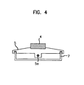
- Fig. 4 is a front view showing an assembly of a rocker and a plate spring of Fig. 3.
- Fig. 5 is a schematic front view showing an operation state of the switch according to the present invention.
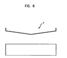
- Fig. 6 shows a modified plate spring of the switch with a rocker according to the present invention.
- Fig. 7 shows a second embodiment of the switch with a rocker according to the present invention.
- Fig. 8 shows a third embodiment of the switch with a rocker according to the present invention.
- Fig. 9 shows another embodiment of a bobbin core of the switch according to the present invention.
- the switch of first embodiment according to the present invention has a supporting plate 3, with a through hole in each corner thereof.
- a base-cover 6 is located under the supporting plate 3.
- Three connectors 11 to 13 are located under the base-cover 6.
- the present invention also has a rocker 5, which is made of a metal that can be magnetized and disposed on the base-cover 6.
- the rocker 5 has a permanently affixed magnet 4 on the upper and center surface thereof and the rocker 5 is magnetized by the attached magnet 4.
- the supporting plate 3 has a first and second solenoids 1 and 2 respectively disposed on both ends of bottom surface thereof.
- the solenoids 1 and 2 have bobbin cores la and 2a respectively therein, so that the solenoids 1 and 2 can function as an electromagnet when a power is supplied.
- the solenoid when a power is supplied to one of the solenoids, the solenoid has an S pole (South Pole) on the lower portion thereof, in accordance with the Fleming's righthand rule.
- the base-cover 6 has supporting bars 6a connected to each through hole on the upper portion thereof, and rocker supporting bars 6b to support the rocker 5 on both sides of the center portion thereof.
- Each rocker supporting bar 6b has a hole on the upper portion thereof. Therefore, when the rocker 5 is disposed on the base-cover 6, the rocker 5 is supported by a rocker pin 5a, which slips into the through hole of the rocker supporting bars 6b and the rocker 5(See Fig. 4). This is to ensure that predetermined space is maintained between the rocker 5 and the solenoids 1 and 2.
- the rocker 5 seesaws about the rocker pin 5a by a perdetermined angle.
- the rocker 5 is permanently magnetized by the attached magnet 4.
- S pole occurs in the lower portion thereof.
- the first solenoid 1 repels the left portion of the rocker 5 downward. Therefore, the right portion of the rocker 5 is contacted with the lower end portion of the second bobbin 2a. In this case, the inclined state of the rocker 5 is retained by an attraction occurred between the first solenoid 1 and the permanent magnet 4.
- the permanent magnet 4 when the power is supplied to the first solenoid 1 so that the left side of the rocker 5 is repelled, the permanent magnet 4 is also tilted in the same direction as the left side of the rocker 5. Accordingly, the permanent magnet 4 closes to the first solenoid 1 so that a force for retaining the inclined state of the rocker 5 is increased by the attraction occurred between the first solenoid 1 and the permanent magnet 4. Further, the friction force is significantly reduced between the through hole of the rocker supporting bars 6b and the rocker pin 5a since the force pulling up the rocker 5 does not exist like the prior art. Therefore, the switching operation can be smoothly performed and the lifecycle of the switch is increased. As a result of a lifecycle test, the switch of the present invention operated over thirteen million times.
- the rocker 5 has a substantially -shaped plate spring 7, in which the erect portion of the plate spring 7 is affixed to the slots 5b of the rocker 5 by an adhesive or a welding.
- the base-cover 6 has two dielectric pins 8 inserted at both end portions thereof. When the rocker 5 is tilted, each dielectric pin 8 is pushed by the plate spring 7 in a downward direction of the base-cover 6. In this case, the plate spring 7 is unlikely to be plastic-deformed.
- the contact areas with the dielectric pin 8, the two erect portions of the plate spring 7, are reinforced by the rocker 5 even though the plate spring 7 pushes the dielectric pin 8 for a long time.
- Each dielectric pin 8 is surrounded by a spring 9.
- the spring 9 provides a restoring force to the dielectric pin 8, so that the dielectric pin 8 returns to its original position when the pressure pushing the dielectric pin 8 is removed.
- the two dielectric pins 8 have reeds 10 and 10' respectively on the lower end portion thereof. Therefore, when the dielectric pin 8 is pushed by the plate spring 7 in the downward direction, the reed 10 contacts two connectors 11 and 12 or the reed 10' contacts two connectors 12 and 13.
- the plate spring 7 when the plate spring 7 is flat, the plate spring 7 may not press the head of the dielectric pin 8a, having a curvature, in the normal direction. Accordingly, this may present the switch of the present invention not to operate. In order to prevent this case, as shown in Fig. 6, it is preferred that the plate spring 7 is convex in the downward direction. That is, when the plate spring 7 is inclined as the Figure 6, the plate spring 7 can always press the head of the dielectric pin 8a in the normal direction.
- the rocker 5 retains the state inclined in the left direction since the permanent magnet 4 closes to the first solenoid 1, i.e., a large attraction occurs between the first solenoid 1 and the permanent magnet 4.
- the plate spring 7 pushes the head of the left dielectric pin 8a downward, which makes the reed 10 to contact the connectors 11 and 12.
- the second embodiment of the switch comprises of a post 14 disposed between the two solenoids 1 and 2.
- the post 14 is changed to an electromagnet having an S pole on the lower portion thereof. Therefore, when the rocker 5 is seesawed, the inclined state of the rocker 5 is retained by a resultant force of the attraction occurred between the solenoid 1 or 2 and the permanent magnet 4 and the attraction occurred between the post 14 and the permanent magnet 4.
- this invention is not limited to the structure which the rocker 5 is magnetized by the permanent magnet 4 disposed on the upper surface thereof. Therefore, as shown in Figure 8, in the third embodiment of the present invention, the rocker 5 has two permanent magnets 4 disposed on both end portions of the upper surface thereof in order to be contacted with the each solenoid disposed on the bottom surface of the supporting plate 3. Therefore, when a power is supplied to a solenoid, the repulsion occurring between each solenoid and the rocker is larger than one occurring in the first or the second embodiment. Therefore, the switch of this embodiment can be used in applications where a strong force is required.
- the length of bobbin core, which extends downward of the solenoid is about 0.5mm, the attraction between the solenoid and the permanent magnet 4 is weak.
- the portion of the rocker 5 contacted with the bobbin core is often removed from the bobbin core under vibration greater than six-gravity.
- the power consumption of the switch is 2.88W(Watts) and the pick-up voltage of the switch is 8V.
- the length of bobbin core, which extends downward of the solenoid is at least 3mm(millimeters) so that the rocker 5 is firmly contacted with the lower portion of the bobbin core.
- the pair-force of the attraction between the solenoid and the permanent magnet and the repulsion between the solenoid and the rocker are stronger compared to the previous embodiments.
- the switch of the present invention operates reliably even under vibration conditions of ten-gravity.
- the switch of the present invention can be used for the military and space applications.
- a switch according to the present invention comprising and operating as above-mentioned, can reliably accomplish the followings:
Abstract
Description
- The present invention relates to a switch with a magnetized rocker utilized in a part of a super-high frequency system such as an N-way power divider/combiner, a radio frequency transmission line and the like. More particularly, it relates to a switch with a rocker capable of being reliably opened or closed by an electromechanical operation.
- Hereinafter, a conventional switch of prior art will be schematically described, referring to Figures 1 and 2.
- As shown in Fig. 1, the conventional switch has a supporting
plate 23, with a through hole in each corner thereof. A base-cover 26 is located under the supportingplate 23. Threeconnectors 31 to 33 are located under the base-cover 26. The conventional switch also has arocker 25, which is made of metal that can be magnetized and disposed on the base-cover 26. - The supporting
plate 23 has a first andsecond solenoids permanent magnet 24 is disposed between the twosolenoids second solenoids second bobbin cores solenoids - The base-
cover 26 has supportingbars 26a connected to each through hole of the supportingplate 23 on each corner thereof, androcker supporting bars 26b to support therocker 25 on both sides of the center portion thereof. Eachrocker supporting bar 26b has a through hole on upper portion thereof. Therefore, when therocker 25 is disposed on the base-cover 26, therocker 25 is supported by arocker pin 35, which slips into the through hole of therocker supporting bar 26b and therocker 25. This is to ensure that predetermined space is maintained between therocker 25 and thesolenoids rocker 25 and thepermanent magnet 24. In this case, therocker 25 seesaws about therocker pin 35 by a predetermined angle. - In the conventional switch, the
rocker 25 is magnetized by thepermanent magnet 24 to cycle in S-N-S pole. That is, when power is supplied to one of the solenoids, themagnetized rocker 25 is tilted by the influence of a mgnetic field from the solenoid. Further, therocker 25 is always pulled in an upward direction by thepermanent magnet 24 disposed on the bottom surface of the supportingplate 23. - The
rocker 25 has aplate spring 27 disposed on the lower portion thereof. The base-cover 26 has twodielectric pins 28 inserted at both end portions thereof. When therocker 25 is tilted, eachdielectric pin 28 is pushed by theplate spring 27 in a downward direction of the base-cover 26. Eachdielectric pin 28 is surrounded by aspring 29. Thespring 29 provides a restoring force to thedielectric pin 28, so that thedielectric pin 28 returns to its original position when the pressure by theplate spring 27 is removed. Eachdielectric pin 28 has areed 30, which contacts with twoconnectors - In conjunction to the conventional switch constructed as described above and as shown in Figure 2, the following explanation applies. When the power is supplied to the
first solenoid 21, S pole (South Pole) occurs in the lower portion thereof. At this time, since the left portion of therocker 25 is an S pole, thefirst solenoid 21 repels the left portion of therocker 25 in the downward direction. At the same time, the right portion of therocker 25 is moved in the upward direction and is contacted with thesecond solenoid 22. In this case, the left portion of theplate spring 27 pushes thedielectric pin 28, positioned in the left side of the base-cover 26, so that theleft reed 30 is contacted with the first andsecond connectors - On the contrary, if an operator supplies the power to the
second solenoid 22, the right portion of therocker 25 having S pole is moved in an downward direction by the described principle as above. Also, the right portion of thespring plate 27 pushes thedielectric pin 28, so that theright reed 30 is contacted with the second andthird connectors spring 29 disconnects theleft reed 30 from the first andsecond connectors - In both cases, the
rocker 25 is always pulled up by the magnetic field of thepermanent magnet 24, disposed in the center portion of the supportingplate 23. - Therefore, the conventional switch requires sufficient power to overcome the friction force between the rocker pin and the through hole of the rocker supporting bars when the switch is operated. Further, the movement of the rocker puts stress on the center portion of the plate spring @(Fig. 2), which has a thickness of 0.1mm - 0.15mm. When the stress is persistent, there is a problem that fatigue happens in the area @. Furthermore, the contacted portion of the plate spring can be plastic-deformed while the plate spring is pushing one of the dielectric pins for a long time. In this case, the connectors cannot be properly contacted reliably by the reed because the pressure provided by the dielectric pin can be weakened due to the plastic deformation of the plate spring.
- It is, therefore, an object of the present invention, the switch with a rocker, which has an affixed magnet, to solve two issues. One is to minimize unnecessary friction force during the switching operation and thereby increasing the reliability with lower power consumption. The other is to prevent the plastic deformation of the plate spring by attaching the both ends of the plate spring to the bottom side of the rocker.
- In order to accomplish the above object, a switch with a rocker, which has an affixed magnet, comprises : a supporting plate; a plurality of electromagnets occurring a magnetic force when a power is supplied thereto, and being disposed on a bottom surface of the supporting plate ; a rocker made of a metal that can be magnetized to occur a repulsion with the electromagnet and being seesawed by a predetermined angle; at least one magnetization means for magnetizing the rocker and retaining an inclined state of the rocker by occurring an attraction with one of the electromagnet and being disposed on the rocker; a pressing means, for providing a pressure along with rotation of the rocker, having erect portion on both end portions thereof, in which the erect portions are fixed to the rocker; and a contact means being contacted with connectors by the pressure of the pressing means.
- The advantage of the present invention will become more apparent to those skilled in the art from the following descriptions when read in conjunction with the accompanying drawings:
- Fig. 1 is a disassembled perspective view showing a switch having a magnetized rocker of the prior art.
- Fig. 2 is a schematic front view showing an operation state of the switch according to the prior art of Fig. 1.
- Fig. 3 is a disassembled perspective view showing the first embodiment of a switch with a rocker according to the present invention.
- Fig. 4 is a front view showing an assembly of a rocker and a plate spring of Fig. 3.
- Fig. 5 is a schematic front view showing an operation state of the switch according to the present invention.
- Fig. 6 shows a modified plate spring of the switch with a rocker according to the present invention.
- Fig. 7 shows a second embodiment of the switch with a rocker according to the present invention.
- Fig. 8 shows a third embodiment of the switch with a rocker according to the present invention.
- Fig. 9 shows another embodiment of a bobbin core of the switch according to the present invention.
- Hereinafter, embodiments of the switch according to the present invention capable of reliably performing a switching operation with lower power consumption and preventing the plastic deformation of the plate spring will be described in detail, referring to the drawings.
- As shown in Figure. 3, the switch of first embodiment according to the present invention has a supporting
plate 3, with a through hole in each corner thereof. A base-cover 6 is located under the supportingplate 3. Threeconnectors 11 to 13 are located under the base-cover 6. The present invention also has arocker 5, which is made of a metal that can be magnetized and disposed on the base-cover 6. In this case, therocker 5 has a permanently affixedmagnet 4 on the upper and center surface thereof and therocker 5 is magnetized by the attachedmagnet 4. - The supporting
plate 3 has a first andsecond solenoids 1 and 2 respectively disposed on both ends of bottom surface thereof. Thesolenoids 1 and 2 have bobbin cores la and 2a respectively therein, so that thesolenoids 1 and 2 can function as an electromagnet when a power is supplied. In this embodiment, when a power is supplied to one of the solenoids, the solenoid has an S pole (South Pole) on the lower portion thereof, in accordance with the Fleming's righthand rule. - The base-
cover 6 has supportingbars 6a connected to each through hole on the upper portion thereof, androcker supporting bars 6b to support therocker 5 on both sides of the center portion thereof. Eachrocker supporting bar 6b has a hole on the upper portion thereof. Therefore, when therocker 5 is disposed on the base-cover 6, therocker 5 is supported by arocker pin 5a, which slips into the through hole of therocker supporting bars 6b and the rocker 5(See Fig. 4). This is to ensure that predetermined space is maintained between therocker 5 and thesolenoids 1 and 2. - In this case, as shown in Figure 5, the
rocker 5 seesaws about therocker pin 5a by a perdetermined angle. In the present invention, therocker 5 is permanently magnetized by the attachedmagnet 4. When power is supplied to the first solenoid 1, S pole occurs in the lower portion thereof. At this time, since the left portion of therocker 5 is an S pole, the first solenoid 1 repels the left portion of therocker 5 downward. Therefore, the right portion of therocker 5 is contacted with the lower end portion of thesecond bobbin 2a. In this case, the inclined state of therocker 5 is retained by an attraction occurred between the first solenoid 1 and thepermanent magnet 4. That is, when the power is supplied to the first solenoid 1 so that the left side of therocker 5 is repelled, thepermanent magnet 4 is also tilted in the same direction as the left side of therocker 5. Accordingly, thepermanent magnet 4 closes to the first solenoid 1 so that a force for retaining the inclined state of therocker 5 is increased by the attraction occurred between the first solenoid 1 and thepermanent magnet 4. Further, the friction force is significantly reduced between the through hole of therocker supporting bars 6b and therocker pin 5a since the force pulling up therocker 5 does not exist like the prior art. Therefore, the switching operation can be smoothly performed and the lifecycle of the switch is increased. As a result of a lifecycle test, the switch of the present invention operated over thirteen million times. - The
rocker 5 has a substantially-shaped
plate spring 7, in which the erect portion of theplate spring 7 is affixed to theslots 5b of therocker 5 by an adhesive or a welding. The base-cover 6 has twodielectric pins 8 inserted at both end portions thereof. When therocker 5 is tilted, eachdielectric pin 8 is pushed by theplate spring 7 in a downward direction of the base-cover 6. In this case, theplate spring 7 is unlikely to be plastic-deformed. The contact areas with thedielectric pin 8, the two erect portions of theplate spring 7, are reinforced by therocker 5 even though theplate spring 7 pushes thedielectric pin 8 for a long time. - Each
dielectric pin 8 is surrounded by aspring 9. Thespring 9 provides a restoring force to thedielectric pin 8, so that thedielectric pin 8 returns to its original position when the pressure pushing thedielectric pin 8 is removed. The twodielectric pins 8 havereeds 10 and 10' respectively on the lower end portion thereof. Therefore, when thedielectric pin 8 is pushed by theplate spring 7 in the downward direction, thereed 10 contacts twoconnectors connectors - Further, when the
plate spring 7 is flat, theplate spring 7 may not press the head of thedielectric pin 8a, having a curvature, in the normal direction. Accordingly, this may present the switch of the present invention not to operate. In order to prevent this case, as shown in Fig. 6, it is preferred that theplate spring 7 is convex in the downward direction. That is, when theplate spring 7 is inclined as the Figure 6, theplate spring 7 can always press the head of thedielectric pin 8a in the normal direction. - In conjunction to the present invention constructed above and as shown in Fig. 5, the following describes how the switch with the magnet rocker is operated.
- As show in Fig. 5, when a power is supplied to the first solenoid 1, S pole occurs in the lower portion thereof. At this time, since the left portion of the
rocker 5 is an S pole, the first solenoid 1 repels the left portion of therocker 5 in downward direction and the right portion of therocker 5 is moved in an upward direction. - In this case, the
rocker 5 retains the state inclined in the left direction since thepermanent magnet 4 closes to the first solenoid 1, i.e., a large attraction occurs between the first solenoid 1 and thepermanent magnet 4. In this case, theplate spring 7 pushes the head of the leftdielectric pin 8a downward, which makes thereed 10 to contact theconnectors - On the contrary, if an operator supplies the power to the
second solenoid 2, the right portion of therocker 5 is repelled downward and the left portion of therocker 5 is contacted to the first solenoid 1 by the above mentioned principle. In this case, the inclined state of therocker 5 is retained by the attraction occurred between thesecond solenoid 2 and thepermanent magnet 4; and theplate spring 7 pushes the head of the rightdielectric pin 8a. Therefore, the reed 10' moved along with descent of thedielectric pin 8 is contacted with theconnectors - Hereinafter, the second and the third embodiments of the present invention will be described, referring to Figures 7 and 8. In describing the second and the third embodiments, overlapping descriptions with the previous embodiment will be omitted.
- As shown in Figure 7, the second embodiment of the switch comprises of a
post 14 disposed between the twosolenoids 1 and 2. In this case, when power is supplied to the switch of this embodiment and therocker 5 is inclined, thepost 14 is changed to an electromagnet having an S pole on the lower portion thereof. Therefore, when therocker 5 is seesawed, the inclined state of therocker 5 is retained by a resultant force of the attraction occurred between thesolenoid 1 or 2 and thepermanent magnet 4 and the attraction occurred between thepost 14 and thepermanent magnet 4. - As the above-mentioned the first and the second embodimnets, this invention is not limited to the structure which the
rocker 5 is magnetized by thepermanent magnet 4 disposed on the upper surface thereof. Therefore, as shown in Figure 8, in the third embodiment of the present invention, therocker 5 has twopermanent magnets 4 disposed on both end portions of the upper surface thereof in order to be contacted with the each solenoid disposed on the bottom surface of the supportingplate 3. Therefore, when a power is supplied to a solenoid, the repulsion occurring between each solenoid and the rocker is larger than one occurring in the first or the second embodiment. Therefore, the switch of this embodiment can be used in applications where a strong force is required. - In the first to third embodiments, the length of bobbin core, which extends downward of the solenoid, is about 0.5mm, the attraction between the solenoid and the
permanent magnet 4 is weak. The portion of therocker 5 contacted with the bobbin core is often removed from the bobbin core under vibration greater than six-gravity. Further, when the coil wound around the solenoid has a resistance of 50(Ohms) and a rated voltage of 12V(Volts), the power consumption of the switch is 2.88W(Watts) and the pick-up voltage of the switch is 8V. - As shown in Fig. 9, it is preferred that the length of bobbin core, which extends downward of the solenoid, is at least 3mm(millimeters) so that the
rocker 5 is firmly contacted with the lower portion of the bobbin core. In this case, the pair-force of the attraction between the solenoid and the permanent magnet and the repulsion between the solenoid and the rocker are stronger compared to the previous embodiments. In this case, since the inclined state of the rocker is more stable, the switch of the present invention operates reliably even under vibration conditions of ten-gravity. Further, when the coil wound around the solenoid has a resistance of 60(Ohms) and a rated voltage of 12V, the power consumption of the switch is 2.4W and the pick-up voltage is 4V. Accordingly, the switch has lower power consumption and lower pick-up voltage compared with the previous switch. Furthermore, since this switch can operated under the vibration at ten-gravity, the switch of the present invention can be used for the military and space applications. - A switch, according to the present invention comprising and operating as above-mentioned, can reliably accomplish the followings:
- 1) The nnecessary friction force is minimized during the switching operation and thereby increasing the reliability with lower power consumption; and
- 2) The lifecycle is extended by preventing plastic deformation and be retained stable contact between the plate spring and the dielectric pin.
-
- If should be understood that the present invention is not limited to the particular embodiments disclosed herein as the best mode contemplated for carrying out the present invetion, and are not limited to the specific embodiments described in this specification except as defined in the appended claims.
Claims (9)
- A switch with a rocker, which has an affixed magnet, comprising :a supporting plate ;a plurality of electromagnets occurring a magnetic force when a power is supplied thereto, and being disposed on a bottom surface of said supporting plate;a rocker made of a metal that can be magnetized to occur a repulsion with said electromagnet, and being seesawed by a predetermined angle;at least one magnetization means for magnetizing said rocker and retaining an inclined state of said rocker by occurring an attraction with one of said electromagnet, and being disposed on said rocker;a pressing means, for providing a pressure along with rotation of said rocker, having erect portion on both end portions thereof, in which said erect portions are fixed to said rocker; anda contact means being contacted with connectors by said pressure of said pressing means.
- The switch according to claim 1, further comprises a means for developing magnetic field occurring an attraction with said magnetization means in order to retain said inclined state of said rocker.
- The switch according to claim 1, wherein said contact means includes a plurality of dielectric members, pushed by said pressure provided from said pressing means, and a plurality of reeds disposed on lower end portion of said each dielectric member in order to be contacted with connectors along with descent of said dielectric members.
- The switch according to claim 3, said contact meams further comprises springs to provide a restoring force to each of said dielectric member, wherein
said dielectric member is restored into its original position by said restoring force of said spring when said pressure pushing said dielectric member is removed. - The switch according to claim 1, wherein each of said electromagnet comprises a soleonid and a bobbin core inserted into said solenoid, wherein
a lower portion of said bobbin core is extended downward of said solenoid by a predetermined length. - The switch according to claim 5, wherein a length of said bobbin core extended downward of said solenoid is about 3millimeters.
- The switch according to claim 1, wherein said pressing means is convex in a downward direction.
- The switch according to claim 7, wherein both side portions of bottom member of said pressing means have a predetermined inclination respectively, wherein
said pressing means pushes said contact means in a substantially normal direction. - The switch according to claim 1, wherein said magnetization means consists of at least one permanent magnet disposed on position faced with said electromagnets.
Applications Claiming Priority (2)
| Application Number | Priority Date | Filing Date | Title |
|---|---|---|---|
| KR1019980011377A KR100286010B1 (en) | 1998-03-31 | 1998-03-31 | switch having a magnetized rocker |
| KR1137798 | 1998-03-31 |
Publications (2)
| Publication Number | Publication Date |
|---|---|
| EP0948018A2 true EP0948018A2 (en) | 1999-10-06 |
| EP0948018A3 EP0948018A3 (en) | 2000-10-18 |
Family
ID=19535680
Family Applications (1)
| Application Number | Title | Priority Date | Filing Date |
|---|---|---|---|
| EP99810277A Withdrawn EP0948018A3 (en) | 1998-03-31 | 1999-03-31 | Switch with a rocker, which has an affixed magnet |
Country Status (4)
| Country | Link |
|---|---|
| US (1) | US6124771A (en) |
| EP (1) | EP0948018A3 (en) |
| JP (1) | JP3254452B2 (en) |
| KR (1) | KR100286010B1 (en) |
Cited By (7)
| Publication number | Priority date | Publication date | Assignee | Title |
|---|---|---|---|---|
| CN105552482A (en) * | 2016-02-05 | 2016-05-04 | 中国电子科技集团公司第四十研究所 | Microwave switch electromagnetic driving device |
| WO2016195810A1 (en) * | 2015-06-04 | 2016-12-08 | Deak David Sr | Rocker action electric generator |
| CN109637899A (en) * | 2019-01-19 | 2019-04-16 | 深圳市沃特沃德股份有限公司 | Relay and electrical equipment |
| CN110164719A (en) * | 2019-06-04 | 2019-08-23 | 珠海格力电器股份有限公司 | Switching device, the method and apparatus for preventing contact adhesion in switching device |
| US11251007B2 (en) | 2017-10-30 | 2022-02-15 | Wepower Technologies Llc | Magnetic momentum transfer generator |
| CN117032264A (en) * | 2023-09-13 | 2023-11-10 | 江苏卓玉智能科技有限公司 | Industrial robot self-adaptive navigation system |
| USRE49840E1 (en) | 2012-04-06 | 2024-02-13 | Wepower Technologies Llc | Electrical generator with rotational gaussian surface magnet and stationary coil |
Families Citing this family (23)
| Publication number | Priority date | Publication date | Assignee | Title |
|---|---|---|---|---|
| US6467987B1 (en) * | 1999-03-29 | 2002-10-22 | Honeywell International Inc. | Resettable non-explosive actuator |
| KR100335321B1 (en) * | 1999-07-22 | 2002-05-06 | 김덕용 | Switch using a magnetized rocker |
| KR100344523B1 (en) * | 2000-07-29 | 2002-07-24 | 주식회사 케이엠더블유 | Radio frequency switch |
| KR20020034821A (en) * | 2000-10-31 | 2002-05-09 | 김덕용 | Radio frequency switch |
| US6650210B1 (en) * | 2003-03-11 | 2003-11-18 | Scientific Components | Electromechanical switch device |
| JP4466505B2 (en) * | 2005-08-12 | 2010-05-26 | オムロン株式会社 | relay |
| US7843289B1 (en) | 2005-08-19 | 2010-11-30 | Scientific Components Corporation | High reliability microwave mechanical switch |
| US7633361B2 (en) * | 2005-08-19 | 2009-12-15 | Scientific Components Corporation | Electromechanical radio frequency switch |
| KR100697654B1 (en) * | 2005-12-01 | 2007-03-20 | 주식회사 에이스테크놀로지 | RF Switch |
| KR100742771B1 (en) * | 2006-01-25 | 2007-07-26 | 주식회사 에이스테크놀로지 | Failsafe type rf switch |
| US8068002B2 (en) * | 2008-04-22 | 2011-11-29 | Magvention (Suzhou), Ltd. | Coupled electromechanical relay and method of operating same |
| DE202008015980U1 (en) * | 2008-12-03 | 2010-04-29 | Eto Magnetic Gmbh | Electromagnetic actuator device |
| US8188817B2 (en) * | 2009-03-11 | 2012-05-29 | Magvention (Suzhou) Ltd. | Electromechanical relay and method of making same |
| DE102010017872B4 (en) * | 2010-04-21 | 2012-06-06 | Saia-Burgess Dresden Gmbh | Bistable small relay of high performance |
| EP2761640B1 (en) * | 2011-09-30 | 2016-08-10 | Telepath Networks, Inc. | Multi integrated switching device structures |
| US20130161167A1 (en) * | 2011-12-23 | 2013-06-27 | Colin Roberts | Switching Device with Auto-Correction of Switching Member |
| KR101216824B1 (en) * | 2011-12-30 | 2012-12-28 | 엘에스산전 주식회사 | Dc power relay |
| US8570126B1 (en) * | 2012-09-28 | 2013-10-29 | Eaton Corporation | Contactless switch with stationary vane |
| CN104008921B (en) * | 2014-06-18 | 2016-02-24 | 中国电子科技集团公司第四十研究所 | High-power RF coaxial relay switch |
| US9425008B1 (en) | 2015-10-30 | 2016-08-23 | Eaton Corporation | Contactless switch with shielded vane |
| US10559433B2 (en) | 2015-12-01 | 2020-02-11 | Switchdown Llc | Switching apparatus for synchronized toggle positioning and related sensory feedback |
| US10249463B1 (en) * | 2016-03-04 | 2019-04-02 | Scientific Components Corporation | Magnetically operated electro-mechanical latching switch |
| KR102001939B1 (en) * | 2017-12-28 | 2019-10-01 | 효성중공업 주식회사 | High speed solenoid |
Citations (3)
| Publication number | Priority date | Publication date | Assignee | Title |
|---|---|---|---|---|
| DE2040291A1 (en) * | 1970-08-13 | 1972-02-17 | Licentia Gmbh | Drive system for a bistable magnetic relay |
| US4496919A (en) * | 1982-02-24 | 1985-01-29 | Micronde | Relay for ultra high frequency coaxial switching |
| US5047740A (en) * | 1990-06-12 | 1991-09-10 | Hewlett-Packard Company | Microwave switch |
-
1998
- 1998-03-31 KR KR1019980011377A patent/KR100286010B1/en not_active IP Right Cessation
-
1999
- 1999-03-22 US US09/273,360 patent/US6124771A/en not_active Expired - Lifetime
- 1999-03-31 EP EP99810277A patent/EP0948018A3/en not_active Withdrawn
- 1999-03-31 JP JP09250599A patent/JP3254452B2/en not_active Expired - Fee Related
Patent Citations (3)
| Publication number | Priority date | Publication date | Assignee | Title |
|---|---|---|---|---|
| DE2040291A1 (en) * | 1970-08-13 | 1972-02-17 | Licentia Gmbh | Drive system for a bistable magnetic relay |
| US4496919A (en) * | 1982-02-24 | 1985-01-29 | Micronde | Relay for ultra high frequency coaxial switching |
| US5047740A (en) * | 1990-06-12 | 1991-09-10 | Hewlett-Packard Company | Microwave switch |
Cited By (12)
| Publication number | Priority date | Publication date | Assignee | Title |
|---|---|---|---|---|
| USRE49840E1 (en) | 2012-04-06 | 2024-02-13 | Wepower Technologies Llc | Electrical generator with rotational gaussian surface magnet and stationary coil |
| WO2016195810A1 (en) * | 2015-06-04 | 2016-12-08 | Deak David Sr | Rocker action electric generator |
| US9843248B2 (en) * | 2015-06-04 | 2017-12-12 | David Deak, SR. | Rocker action electric generator |
| CN105552482A (en) * | 2016-02-05 | 2016-05-04 | 中国电子科技集团公司第四十研究所 | Microwave switch electromagnetic driving device |
| CN105552482B (en) * | 2016-02-05 | 2019-07-16 | 中国电子科技集团公司第四十研究所 | Microwave switch electromagnetic actuator device |
| US11251007B2 (en) | 2017-10-30 | 2022-02-15 | Wepower Technologies Llc | Magnetic momentum transfer generator |
| US11915898B2 (en) | 2017-10-30 | 2024-02-27 | Wepower Technologies Llc | Magnetic momentum transfer generator |
| CN109637899A (en) * | 2019-01-19 | 2019-04-16 | 深圳市沃特沃德股份有限公司 | Relay and electrical equipment |
| CN109637899B (en) * | 2019-01-19 | 2019-12-17 | 深圳市沃特沃德股份有限公司 | Relay and electric equipment |
| CN110164719A (en) * | 2019-06-04 | 2019-08-23 | 珠海格力电器股份有限公司 | Switching device, the method and apparatus for preventing contact adhesion in switching device |
| CN110164719B (en) * | 2019-06-04 | 2020-05-19 | 珠海格力电器股份有限公司 | Switching device, method and apparatus for preventing contact adhesion in switching device |
| CN117032264A (en) * | 2023-09-13 | 2023-11-10 | 江苏卓玉智能科技有限公司 | Industrial robot self-adaptive navigation system |
Also Published As
| Publication number | Publication date |
|---|---|
| US6124771A (en) | 2000-09-26 |
| KR100286010B1 (en) | 2001-04-16 |
| JP3254452B2 (en) | 2002-02-04 |
| JPH11340703A (en) | 1999-12-10 |
| KR19990076435A (en) | 1999-10-15 |
| EP0948018A3 (en) | 2000-10-18 |
Similar Documents
| Publication | Publication Date | Title |
|---|---|---|
| US6124771A (en) | Switch with a rocker, which has an affixed magnet | |
| EP1513176B1 (en) | Linear switch actuator | |
| KR100388768B1 (en) | Electromagnetic relay | |
| JP5989225B2 (en) | Polarized electromagnetic relay and manufacturing method thereof | |
| EP1052666A2 (en) | Switch using solenoid | |
| US6639493B2 (en) | Micro machined RF switches and methods of operating the same | |
| CN100397713C (en) | Electronic device and its storage card connecting mechanism | |
| US5703550A (en) | Magnetic latching relay | |
| US20060114085A1 (en) | System and method for routing input signals using single pole single throw and single pole double throw latching micro-magnetic switches | |
| US5945900A (en) | Electromagnetic contactor | |
| JPWO2010073317A1 (en) | Magnetic contactor | |
| EP0360271B1 (en) | Electromagnetic polar relay | |
| EP0277833A2 (en) | Polarized electromagnetic relay | |
| US5162764A (en) | Slim-type polarized electromagnetic relay | |
| US6356174B1 (en) | Operator for an electromagnetic switching device | |
| JP4331086B2 (en) | Electromagnetic actuator and optical device using the same | |
| CN210120089U (en) | Ammeter connection structure capable of opening and closing circuit and electric energy meter comprising same | |
| JP2003317596A (en) | Electromagnetic relay | |
| JPH05174691A (en) | Seesaw balance type polarized relay | |
| JP3147427B2 (en) | Electromagnetic relay | |
| CN115116795A (en) | Electromagnetic relay | |
| JPH113645A (en) | Electromagnetic contactor | |
| JPH0119309Y2 (en) | ||
| JPH0240828A (en) | Electromagnetic relay | |
| JPS61151940A (en) | Polar relay |
Legal Events
| Date | Code | Title | Description |
|---|---|---|---|
| PUAI | Public reference made under article 153(3) epc to a published international application that has entered the european phase |
Free format text: ORIGINAL CODE: 0009012 |
|
| AK | Designated contracting states |
Kind code of ref document: A2 Designated state(s): DE FI FR GB SE |
|
| AX | Request for extension of the european patent |
Free format text: AL;LT;LV;MK;RO;SI |
|
| PUAL | Search report despatched |
Free format text: ORIGINAL CODE: 0009013 |
|
| AK | Designated contracting states |
Kind code of ref document: A3 Designated state(s): AT BE CH CY DE DK ES FI FR GB GR IE IT LI LU MC NL PT SE |
|
| AX | Request for extension of the european patent |
Free format text: AL;LT;LV;MK;RO;SI |
|
| 17P | Request for examination filed |
Effective date: 20010321 |
|
| AKX | Designation fees paid |
Free format text: DE FI FR GB SE |
|
| GRAP | Despatch of communication of intention to grant a patent |
Free format text: ORIGINAL CODE: EPIDOSNIGR1 |
|
| STAA | Information on the status of an ep patent application or granted ep patent |
Free format text: STATUS: THE APPLICATION IS DEEMED TO BE WITHDRAWN |
|
| 18D | Application deemed to be withdrawn |
Effective date: 20050426 |