US12059337B2 - Surgical textile with barbs and loops - Google Patents
Surgical textile with barbs and loops Download PDFInfo
- Publication number
- US12059337B2 US12059337B2 US17/230,971 US202117230971A US12059337B2 US 12059337 B2 US12059337 B2 US 12059337B2 US 202117230971 A US202117230971 A US 202117230971A US 12059337 B2 US12059337 B2 US 12059337B2
- Authority
- US
- United States
- Prior art keywords
- textile
- barbs
- loops
- diameter
- face
- Prior art date
- Legal status (The legal status is an assumption and is not a legal conclusion. Google has not performed a legal analysis and makes no representation as to the accuracy of the status listed.)
- Active, expires
Links
Images


Classifications
-
- A—HUMAN NECESSITIES
- A61—MEDICAL OR VETERINARY SCIENCE; HYGIENE
- A61F—FILTERS IMPLANTABLE INTO BLOOD VESSELS; PROSTHESES; DEVICES PROVIDING PATENCY TO, OR PREVENTING COLLAPSING OF, TUBULAR STRUCTURES OF THE BODY, e.g. STENTS; ORTHOPAEDIC, NURSING OR CONTRACEPTIVE DEVICES; FOMENTATION; TREATMENT OR PROTECTION OF EYES OR EARS; BANDAGES, DRESSINGS OR ABSORBENT PADS; FIRST-AID KITS
- A61F2/00—Filters implantable into blood vessels; Prostheses, i.e. artificial substitutes or replacements for parts of the body; Appliances for connecting them with the body; Devices providing patency to, or preventing collapsing of, tubular structures of the body, e.g. stents
- A61F2/0063—Implantable repair or support meshes, e.g. hernia meshes
-
- D—TEXTILES; PAPER
- D04—BRAIDING; LACE-MAKING; KNITTING; TRIMMINGS; NON-WOVEN FABRICS
- D04B—KNITTING
- D04B21/00—Warp knitting processes for the production of fabrics or articles not dependent on the use of particular machines; Fabrics or articles defined by such processes
- D04B21/10—Open-work fabrics
- D04B21/12—Open-work fabrics characterised by thread material
-
- A—HUMAN NECESSITIES
- A61—MEDICAL OR VETERINARY SCIENCE; HYGIENE
- A61F—FILTERS IMPLANTABLE INTO BLOOD VESSELS; PROSTHESES; DEVICES PROVIDING PATENCY TO, OR PREVENTING COLLAPSING OF, TUBULAR STRUCTURES OF THE BODY, e.g. STENTS; ORTHOPAEDIC, NURSING OR CONTRACEPTIVE DEVICES; FOMENTATION; TREATMENT OR PROTECTION OF EYES OR EARS; BANDAGES, DRESSINGS OR ABSORBENT PADS; FIRST-AID KITS
- A61F2/00—Filters implantable into blood vessels; Prostheses, i.e. artificial substitutes or replacements for parts of the body; Appliances for connecting them with the body; Devices providing patency to, or preventing collapsing of, tubular structures of the body, e.g. stents
- A61F2/0063—Implantable repair or support meshes, e.g. hernia meshes
- A61F2002/0068—Implantable repair or support meshes, e.g. hernia meshes having a special mesh pattern
-
- A—HUMAN NECESSITIES
- A61—MEDICAL OR VETERINARY SCIENCE; HYGIENE
- A61F—FILTERS IMPLANTABLE INTO BLOOD VESSELS; PROSTHESES; DEVICES PROVIDING PATENCY TO, OR PREVENTING COLLAPSING OF, TUBULAR STRUCTURES OF THE BODY, e.g. STENTS; ORTHOPAEDIC, NURSING OR CONTRACEPTIVE DEVICES; FOMENTATION; TREATMENT OR PROTECTION OF EYES OR EARS; BANDAGES, DRESSINGS OR ABSORBENT PADS; FIRST-AID KITS
- A61F2210/00—Particular material properties of prostheses classified in groups A61F2/00 - A61F2/26 or A61F2/82 or A61F9/00 or A61F11/00 or subgroups thereof
- A61F2210/0004—Particular material properties of prostheses classified in groups A61F2/00 - A61F2/26 or A61F2/82 or A61F9/00 or A61F11/00 or subgroups thereof bioabsorbable
-
- A—HUMAN NECESSITIES
- A61—MEDICAL OR VETERINARY SCIENCE; HYGIENE
- A61F—FILTERS IMPLANTABLE INTO BLOOD VESSELS; PROSTHESES; DEVICES PROVIDING PATENCY TO, OR PREVENTING COLLAPSING OF, TUBULAR STRUCTURES OF THE BODY, e.g. STENTS; ORTHOPAEDIC, NURSING OR CONTRACEPTIVE DEVICES; FOMENTATION; TREATMENT OR PROTECTION OF EYES OR EARS; BANDAGES, DRESSINGS OR ABSORBENT PADS; FIRST-AID KITS
- A61F2220/00—Fixations or connections for prostheses classified in groups A61F2/00 - A61F2/26 or A61F2/82 or A61F9/00 or A61F11/00 or subgroups thereof
- A61F2220/0008—Fixation appliances for connecting prostheses to the body
- A61F2220/0016—Fixation appliances for connecting prostheses to the body with sharp anchoring protrusions, e.g. barbs, pins, spikes
-
- A—HUMAN NECESSITIES
- A61—MEDICAL OR VETERINARY SCIENCE; HYGIENE
- A61F—FILTERS IMPLANTABLE INTO BLOOD VESSELS; PROSTHESES; DEVICES PROVIDING PATENCY TO, OR PREVENTING COLLAPSING OF, TUBULAR STRUCTURES OF THE BODY, e.g. STENTS; ORTHOPAEDIC, NURSING OR CONTRACEPTIVE DEVICES; FOMENTATION; TREATMENT OR PROTECTION OF EYES OR EARS; BANDAGES, DRESSINGS OR ABSORBENT PADS; FIRST-AID KITS
- A61F2220/00—Fixations or connections for prostheses classified in groups A61F2/00 - A61F2/26 or A61F2/82 or A61F9/00 or A61F11/00 or subgroups thereof
- A61F2220/0025—Connections or couplings between prosthetic parts, e.g. between modular parts; Connecting elements
- A61F2220/0083—Connections or couplings between prosthetic parts, e.g. between modular parts; Connecting elements using hook and loop-type fasteners
-
- A—HUMAN NECESSITIES
- A61—MEDICAL OR VETERINARY SCIENCE; HYGIENE
- A61F—FILTERS IMPLANTABLE INTO BLOOD VESSELS; PROSTHESES; DEVICES PROVIDING PATENCY TO, OR PREVENTING COLLAPSING OF, TUBULAR STRUCTURES OF THE BODY, e.g. STENTS; ORTHOPAEDIC, NURSING OR CONTRACEPTIVE DEVICES; FOMENTATION; TREATMENT OR PROTECTION OF EYES OR EARS; BANDAGES, DRESSINGS OR ABSORBENT PADS; FIRST-AID KITS
- A61F2240/00—Manufacturing or designing of prostheses classified in groups A61F2/00 - A61F2/26 or A61F2/82 or A61F9/00 or A61F11/00 or subgroups thereof
- A61F2240/001—Designing or manufacturing processes
-
- D—TEXTILES; PAPER
- D10—INDEXING SCHEME ASSOCIATED WITH SUBLASSES OF SECTION D, RELATING TO TEXTILES
- D10B—INDEXING SCHEME ASSOCIATED WITH SUBLASSES OF SECTION D, RELATING TO TEXTILES
- D10B2501/00—Wearing apparel
- D10B2501/06—Details of garments
- D10B2501/063—Fasteners
- D10B2501/0632—Fasteners of the touch-and-close type
-
- D—TEXTILES; PAPER
- D10—INDEXING SCHEME ASSOCIATED WITH SUBLASSES OF SECTION D, RELATING TO TEXTILES
- D10B—INDEXING SCHEME ASSOCIATED WITH SUBLASSES OF SECTION D, RELATING TO TEXTILES
- D10B2509/00—Medical; Hygiene
- D10B2509/08—Hernia repair mesh
Definitions
- the present invention relates to a surgical textile provided at least on one of its faces with barbs and loops, the barbs being capable of being deactivated when the surgical textile is conveyed to an implantation site.
- a surgical textile can particularly be used for producing tissue-reinforcing prostheses intended to be introduced into a patient, either by a classical open surgery route or by minimally invasive surgery.
- Tissue-reinforcing prostheses for example prostheses for reinforcing the abdominal wall, are widely used in the surgical field. These prostheses are intended to treat hernias by temporarily or permanently filling a tissue defect. These prostheses are generally made of biocompatible prosthetic fabric and can have a number of shapes, for example rectangular, circular or oval, depending on the anatomical structure to which they are to be fitted. Some of these prostheses are made from entirely bioresorbable yarns and are intended to disappear after having carried out their reinforcing role while cell colonization takes place and tissue rehabilitation takes over. Other prostheses comprise non-biodegradable yarns and are intended to remain permanently in the body of the patient.
- Some of these prostheses comprise an arrangement of yarns, such as a knit, a woven fabric or non-woven fabric, comprising barbs that protrude outwards from one face, sometimes from the two faces, of the prosthesis: these barbs constitute hooks that are able to fix themselves either in another prosthetic fabric, belonging to the same prosthesis or not, or directly in the biological tissues, for example the abdominal wall.
- barbs on at least one face of a surgical textile to be implanted in a patient has therefore the advantage of enabling the surgical textile to directly grip to the biological tissue, so that it is possible to fix the surgical textile without having to use conventional attaching means such as staples, sutures, which may be traumatizing for the biological tissues and which may in addition cause tensions in the biological tissues and/or cause tearing in the textile.
- surgical textiles with barbs may also leave the surgeon with some negative perceptions, those negative perceptions making such surgical textiles challenging to implant.
- Minimally invasive surgery requires only very small incisions, through which a trocar is passed, within which the prosthesis is conveyed to the implantation site.
- An advantage of minimally invasive surgery is that open surgery is avoided, allowing the patient to leave hospital rapidly.
- Minimally invasive surgery is particularly popular in surgical operations carried out in the abdomen, such as for example the treatment of hernias.
- the trocars used in minimally invasive surgery generally have a relatively small calibrated diameter, which may vary, for example, from 5 to 15 mm, in order to reduce the size of the incision made as much as possible.
- the prosthesis must therefore be conveyed within a channel of reduced diameter and it must then be deployed at the implantation site.
- the prosthesis is generally rolled up on itself in order to make it slide in the channel of the trocar or directly introduced by force.
- the surgical textile forming the prosthesis comprises barbs at least on one face, it may happen that these barbs become entangled in the body of the textile and hinder the subsequent deployment of the prosthesis at the implantation site. Deploying and spreading out the surgical textile on the implantation site may therefore constitute a challenge for the surgeon.
- the barbs may be damaged during the unrolling of the surgical textile or during its transportation through the trocar to the implantation site.
- An aspect of the invention is a surgical textile provided with barbs, said surgical textile being further provided with means capable of deactivating the barbs before said barbs have to play their gripping function.
- the invention relates to a surgical textile comprising an arrangement of biocompatible yarns defining a first face and a second face of the textile, the second face opposite the first face, the textile being provided at least on an area of a surface of one of its faces with a plurality of barbs showing substantially a first length L 1 , measured perpendicularly to that surface, characterised in that said area of said surface is further provided with a plurality of loops, said loops showing substantially a second length L 2 , measured perpendicularly to that surface, where L 2 is greater than L 1 .
- the barbs of the surgical textile according to the invention may protrude from a face of the textile substantially perpendicularly to the plane of said face or alternatively along one or more planes that are inclined relative to the plane of said face.
- These barbs are intended to function as fastening means, either by becoming entangled in one or more arrangements of yarns, fibres, filaments and/or multifilaments of another prosthetic fabric, for example in order to form a composite reinforcing prosthesis, or by anchoring directly in the biological tissues, such as for example an abdominal wall, once the prosthesis comprising this surgical textile or constituted of this surgical textile is implanted.
- the perpendicular lengths of the barbs L 1 and of the loops L 2 are measured from the surface of the face of the textile from which they protrude, as the distance between that surface and the furthest point of the barb or of the loop from that surface, along a perpendicular line to that surface.
- the true length of the barbs i.e. the distance between the foot of the barb and its head along a longitudinal axis of the barb
- the true length of the loops i.e. the distance between the basis of the loop and its apex along a longitudinal axis of the loop, may be different from their respective perpendicular lengths as defined above.
- the barbs and/or the loops may extend perpendicularly to the surface of the face of the textile, in which case their perpendicular lengths are substantially identical to their true lengths, but they also alternatively may extend obliquely from that surface, in which case their perpendicular lengths is smaller than their true lengths.
- the surgical textile of the invention allows deactivating the barbs before they have to grip another fabric or the biological tissue at the implantation site.
- the loops of the textile of the invention allow protecting the barbs while the textile is conveyed to the implantation site.
- the loops because of their perpendicular length L 2 being greater than the barbs' perpendicular length L 1 , prevent the barbs to anchor into the tissues. The gripping function of the barbs is therefore deactivated.
- the surgical textile Once the surgical textile has reached the implantation site, it is positioned so that the face of the textile provided with the barbs and the loops faces the biological tissues to which the textile is intended to be fixed. The surgeon may then apply a pressure on the face of the textile opposite the face provided with the barbs and the loops. The pressure thus applied on the textile in the direction of the biological tissue will cause the loops to flatten, and the barbs will protrude outwards and will be able to grip said biological tissue. The gripping function of the barbs is therefore activated.
- the barbs may be deactivated during the introduction of the textile in the body of the patient, during the deployment of the textile and during the potential repositioning of the textile: all these steps are therefore rendered easier to perform for the surgeon.
- the barbs may be activated only when the surgeon feels the need to do so, for example when he feels the textile is a the right position, simply by applying a pressure on the textile: such a step is also easy to perform.
- L 2 may be from 20% to 140% longer than L 1 , preferably from 40% to 100% longer than L 1 .
- L 2 may be 80% longer than L 1 .
- L 1 may range from 0.5 mm to 1.0 mm, preferably from 0.7 mm to 0.9 mm, and L 2 may range from 0.8 mm to 1.2 mm, preferably from 0.9 mm to 1.1 mm.
- the barbs and the loops of the surgical textile of the invention are made of biocompatible material.
- the barbs and the loops are made of yarns or of yarn cuts, for example of yarns of said arrangement of yarns.
- the barbs and the loops may be made of the same yarns or of different yarns.
- the barbs are made of a yarn having a diameter D 1 and the loops are made of a yarn having a diameter D 2 , where D 1 is greater than D 2 .
- Such embodiments allow providing a surgical textile for which the force to apply to anchor the barbs into a biological tissue or other fabric may be moderate. Indeed, the fact that D 2 is smaller than D 1 allows obtaining barbs that show a significant strength or rigidity while the loops show a moderate spring effect. The risk that the textile uplifts due to the presence of the loops is therefore reduced. The activation of the barbs is facilitated since the force necessary to reduce/flatten the loops may be reduced.
- D 1 may be from 10% to 80% greater than D 2 , preferably from 15% to 40% greater than the diameter D 2 .
- D 1 may be 25% greater than D 2 .
- D 1 may range from 0.10 mm to 0.18 mm, preferably from 0.11 mm to 0.16 mm, and D 2 may range from 0.09 mm to 0.17 mm, preferably from 0.10 mm to 0.15 mm.
- the barbs are made of a yarn having a diameter D 3 and the loops are made of a yarn having a diameter D 4 , where D 4 is greater than D 3 .
- Such embodiments allow providing a surgical textile particularly efficient for avoiding that the barbs anchor the surrounding biological tissues before the surgical textile reaches the implantation site. Indeed, the fact that the diameter D 4 is greater than D 3 produces stiffer loops that ensure that the barbs are prevented from gripping to the biological tissues before the surgeon actually decides it. The deactivation of the barbs is therefore particularly efficient, and the barbs do not penetrate the tissue or another fabric before the surgeon decides to apply the necessary pressure on the textile.
- D 4 may be from 10% to 80% greater than D 3 , preferably from 15% to 40% greater than D 3 .
- D 4 may range from 0.10 mm to 0.18 mm, preferably from 0.11 mm to 0.16 mm, and D 3 may range from 0.09 mm to 0.17 mm, preferably from 0.10 mm to 0.15 mm.
- the yarns of the textile of the invention are yarns of biocompatible material which may or may not be biodegradable.
- biocompatible is understood as meaning that the materials having this property can be implanted in the human or animal body.
- biocompatible materials may be synthetic or natural, biodegradable, non-biodegradable or a combination of biodegradable and non-biodegradable.
- biodegradable as used herein is defined to include both bioabsorbable and bioresorbable materials. By biodegradable, it is meant that the materials decompose, or lose structural integrity under body conditions (e.g. enzymatic degradation or hydrolysis) or are broken down (physically or chemically) under physiologic conditions in the body such that the degradation products are excretable or absorbable by the body.
- the yarns forming the first and second faces of the textile, the loops and the barbs may be made of any biodegradable or non-biodegradable biocompatible material.
- the biodegradable materials suitable for the yarns forming the first and second faces of the textile, the loops and the barbs of the surgical textile of the present invention may be selected from polylactic acid (PLA), polyglycolic acid (PGA), oxidized cellulose, polycaprolactone (PCL), polydioxanone (PDO), trimethylene carbonate (TMC), polyvinyl alcohol (PVA), polyhydroxyalkanoates (PHAs), copolymers thereof and mixtures thereof.
- the non-biodegradable materials suitable for the yarns forming the first and second faces of the textile, the loops and the barbs of the surgical textile of the present invention may be selected from polyethylene terephthalate (PET), polyamides, aramids, expanded polytetrafluoroethylene, polyurethane, polyvinylidene difluoride (PVDF), butyl ester polymers, polyetheretherketone (PEEK), polyolefins (such as polyethylene or polypropylene), polyethers, copper alloys, silver or platinum alloys, medical grades of steel such as medical-grade stainless steel, and combinations thereof.
- PET polyethylene terephthalate
- PVDF polyamides
- aramids expanded polytetrafluoroethylene
- PVDF polyurethane
- PVDF polyvinylidene difluoride
- PEEK polyetheretherketone
- polyolefins such as polyethylene or polypropylene
- polyethers copper alloys, silver or platinum alloys
- the barbs are made of a biodegradable material. Such embodiments allow providing a surgical textile that limits the introduction of foreign material in the body of the patient. Once the surgical textile is colonized by the biological tissue and the gripping function of the barbs is no more necessary, the barbs are biodegraded.
- the barbs are made of heat-fusible monofilament yarn cuts.
- the heat-fusible monofilament yarn cuts are made of polylactic acid monofilament yarn having a diameter of 0.15 mm: such a yarn having such a diameter makes it possible to obtain barbs that have good anchoring abilities in biological tissues or in another openwork fabric.
- the yarns forming the first and second faces of the textile constitute the ground structure of the surgical textile, in other words the background of the textile, and they may be selected from monofilament yarns, multifilament yarns and combinations thereof.
- the yarns forming the first and second faces of the textile may be identical or different from the yarns forming the loops and the barbs.
- the yarns forming the first and second faces of the textile are monofilament yarns made of polyester terephthalate (PET) having a diameter of 0.09 mm.
- PET polyester terephthalate
- the yarns forming the loops are monofilament yarns made of polylactic acide (PLA) having a diameter of 0.15 mm.
- PLA polylactic acide
- Such yarns have an intrinsic stiffness allowing obtaining stiffer loops.
- the arrangement of yarns of the surgical textile of the invention is a knit comprising i) one or more yarn(s) forming the first and second faces of the textile and the loops and ii) heat-fusible monofilament yarn cuts forming the barbs.
- the knit may be obtained on a warp knitting machine or Raschel knitting machine.
- the area of the face of the knit provided with the barbs and the loops may show columns of loops alternating with columns of barbs.
- the loops and the barbs may be randomly distributed in the area.
- the loops and the barbs define looped zones and barbed zones organised according to patterns selected from stripes, concentric circles, concentric rectangles, concentric squares, quincunx, and combinations thereof.
- the barbs may be obtained by melting loops generated by a heat-fusible monofilament yarn used in the knitting process.
- the barbs have the shape of a shaft, having the diameter of the yarn used for their formation, surmounted by a head having a diameter greater than that of the shaft.
- the generation of barbs from preliminary loops made of heat-fusible monofilament yarn is known and is described, for example in document WO 01/81667.
- the heat-fusible monofilament yarn used in the knitting process to form the barbs is made of a bioresorbable material.
- the heat-fusible monofilament yarn is a polylactic acid monofilament yarn having a diameter of 0.15 mm: such a yarn having such a diameter makes it possible to obtain barbs that have good anchoring abilities in biological tissues or in another openwork textile.
- the heat-fusible monofilament yarn may be a polylactic acid monofilament yarn having a diameter of 0.12 mm.
- Another aspect of the invention is a process for manufacturing a surgical textile comprising a first face and a second face, opposite the first face, comprising the following steps:
- the cutting of step B) may be performed by contacting the loops with a cylinder that is brought to a temperature that causes the loops to melt so that they are cut in two and thus form the barbs, as described in WO01/81667. This cutting generates two barbs, each of them having a head with dimensions usually greater than its shaft.
- step B) is performed by heating a press to a temperature that causes the loops to melt and applying said heated press on said first face of the knit, said press being shaped and dimensioned so that only some of the loops are contacted by said press and are thus caused to melt.
- two different heat-fusible monofilament yarns are used in step A) of the process above, a first heat-fusible monofilament yarn having a first diameter and generating first loops, and a second heat-fusible monofilament yarn having a second diameter and generating second loops, and only the first loops are cut by melting during step B).
- the first diameter is greater than the second diameter.
- the second diameter is greater than the first diameter.
- the knit may be produced on a warp knitting machine having four guide bars B 1 , B 2 , B 3 and B 4 , where B 1 is unthreaded, and B 2 , B 3 and B 4 are threaded according to the following knitting pattern, according to the ISO 11676 standard (publication year 2014):
- the yarns threaded in guide bars B 2 and B 3 are monofilament yarns of polyester terephthalate (PET) having a diameter of 0.09 mm and form the first and second faces of the textile
- the yarn threaded in guide bar B 4 is a heat-fusible monofilament yarn, for example a polylactic acid monofilament yarn, and produces the loops.
- the knit may be produced on a warp knitting machine with four guide bars B 1 , B 2 , B 3 and B 4 , according to the following knitting pattern according to the standard ISO 11676 (publication year 2014):
- the knitting patterns of the process above may produce openwork faces for the textile, such open work faces favouring cell recolonization.
- openwork face is understood to mean that said face comprises openings or pores: these openings or pores are in particular generated by the knitting pattern followed for the knitting of the yarns in the process above, and may correspond to the various meshes of said knit.
- the surgical textile according to the invention can be used as is in order to constitute a reinforcing prosthesis for repairing a hernia, or it may constitute one part of a reinforcing prosthesis for repairing hernias.
- the surgical textile can also be conveyed to the surgical site directly through the surrounding tissues, via open surgery, without damaging the tissues.
- the textile can then be fastened either to another fabric, or to a biological wall, owing to the anchoring abilities of the barbs, by applying a pressure to the textile, to flatten the loops and activate the barbs.
- the two faces of the textile may be provided with areas having a plurality of loops and a plurality of barbs.
- FIG. 1 A is a schematic cross section view of a first embodiment of a textile according to the invention
- FIG. 1 B is a schematic cross section view of a second embodiment of a textile of the invention with its face provided with barbs and loops facing a biological tissue,
- FIG. 1 C is a schematic cross section view of the textile and biological tissue of FIG. 1 B once the surgeon has applied a pressure to the textile to anchor it to the biological tissue,
- FIG. 1 D is a schematic cross section view of the textile of FIG. 1 B , which has been folded on itself,
- FIG. 1 E is a schematic cross section view of the textile of FIG. 1 B , which has been rolled on itself,
- FIG. 2 is a schematic cross section view of a third embodiment of a textile according to the invention.
- FIG. 3 is a schematic cross section view of a fourth embodiment of a textile according to the invention.
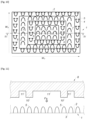
- FIG. 4 is a schematic top view of the face of the textile of the invention, in which the looped zones and the barbed zones are organised according to a pattern forming stripes,
- FIG. 5 is a schematic cross section view along plane I-I of the textile of FIG. 4 before the melting step of the loops and of the press used for the melting step,
- FIG. 6 is a schematic top view of the face of the textile of the invention, in which the looped zones and the barbed zones are organised according to a pattern forming a quincunx,
- FIG. 7 is a schematic cross section view along plane II-II of the textile of FIG. 6 before the melting step of the loops and of the press used for the melting step,
- FIG. 8 is a schematic top view of the face of the textile of the invention, in which the looped zones and the barbed zones are organised according to a pattern forming concentric circles,
- FIG. 9 is a schematic cross section view along plane of the textile of FIG. 8 before the melting step of the loops and of the press used for the melting step,
- FIG. 10 is a schematic top view of the face of the textile of the invention, in which the looped zones and the barbed zones are organised according to a pattern forming concentric rectangles,
- FIG. 11 is a schematic cross section view along plane IV-IV of the textile of FIG. 10 before the melting step of the loops and of the press used for the melting step,
- FIG. 12 is a graph showing the self-gripping properties of textiles of the invention and of comparative textiles.
- the surgical textile 1 has a first face 2 and a second face 3 , opposite the first face 2 .
- the textile 1 comprises an arrangement of yarns forming the background of the textile 1 and defining said first face 2 and second face 3 .
- the first face 2 is provided with a plurality of barbs 4 and with a plurality of loops 5 .
- the barbs 4 have a foot 4 a and a head 4 b .
- the loops 5 have a basis 5 a and an apex 5 b.
- the barbs 4 and the loops 5 extend substantially perpendicularly with respect to the surface of the first face 2 : the length L 1 of a barb 4 , measured perpendicularly to said surface, corresponds therefore to the length of the barb 4 between its foot 4 a and its head 4 b measured according to a longitudinal axis of the barb 4 , and the length L 2 of a loop 5 , measured perpendicularly to said surface, corresponds therefore to the length of the loop 5 between its basis 5 a and its apex 5 b measured according to a longitudinal axis of the loop 5 .
- the length L 2 is greater than the length L 1 .
- L 1 may range from 0.5 mm to 1.0 mm, preferably from 0.7 mm to 0.9 mm, and L 2 may range from 0.8 mm to 1.2 mm, preferably from 0.9 mm to 1.1 mm.
- the loops 5 of the textile 1 allow protecting the barbs 4 when the textile 1 is conveyed to an implantation site. During the time the textile 1 is moved within the surrounding tissues, the loops 5 prevent the barbs 4 to anchor into the tissues.
- FIGS. 1 B and 1 C are schematic cross section views of a textile 1 similar to that of FIG. 1 A , at the vicinity of a biological tissue 12 , when the textile 1 is being conveyed to the implantation site and the barbs 4 are deactivated, and further on when the textile 1 is being anchored to the biological tissue 12 by activation of the barbs 4 .
- the apexes 5 b of the loops 5 are in contact with the outer surface 12 a of the biological tissue 12 .
- the loops 5 thereby maintain the outer surface 12 a of the biological tissue 12 away from the heads 4 b of the barbs 4 .
- the barbs 4 are therefore protected, their gripping function is deactivated, and the transport of the textile 1 up to the implantation site is facilitated, as the barbs 4 are prevented from anchoring into the biological tissue 12 .
- the textile 1 is positioned so that its first face 2 , provided with the barbs 4 and the loops 5 , faces the outer surface 12 a of the biological tissue 12 to which the textile 1 is intended to be fixed.
- the surgeon may then apply a pressure, shown by an arrow P on this Figure, on top of the second face 3 of the textile 1 .
- the pressure applied on the second face 3 of the textile 1 in the direction of the biological tissue 12 causes the loops 5 to flatten, and the barbs 4 to contact the outer surface 12 a of the biological tissue and enter into the biological tissue 12 .
- the heads 4 b of the barbs 4 are then able to grip the biological tissue 12 .
- the gripping function of the barbs 4 is activated.
- the textile 1 allows therefore deactivating the barbs 4 during the time the textile 1 is conveyed to the implantation site, either through surrounding tissues, or in a folded or rolled configuration of the textile 1 in a trocar, and activating the barbs 4 when needed.
- FIG. 1 D With reference to FIG. 1 D is shown the textile 1 of FIGS. 1 B- 1 C in a configuration in which the textile 1 is folded on itself.
- the respective apexes 5 b of two loops 5 facing each other contact themselves, thereby maintaining a safety space 13 between the heads 4 b of two barbs 4 facing each other.
- the barbs 4 are therefore protected and deactivated, and they are prevented from becoming entangled with each other as well as with the background of the textile 1 .
- FIG. 1 E With reference to FIG. 1 E is shown the textile 1 of FIGS. 1 B- 1 D in a configuration in which it has been rolled on itself, for example for introduction inside a trocar.
- the apexes 5 b of the loops 5 contact the second face 3 of the textile 1 , thereby maintaining the barbs 4 , and in particular their heads 4 b , away from this second face 3 of the textile 1 .
- the barbs 4 are therefore protected and deactivated, and prevented from becoming entangled in the background of the textile 1 .
- the deactivation of the barbs 4 also allows an easier deployment of the textile 1 once it has reached the implantation site.
- the deactivation of the barbs 4 by the loops 5 also allows the textile 1 to be detached and re-attached easily on the implantation site, so that the surgeon may reposition the textile 1 in order to fix it in the best position.
- FIG. 2 is a schematic view of a textile 1 similar to that of FIG. 1 A , in which the barbs 4 extend obliquely with respect to the surface of the first face 2 .
- the length l 1 of a barb 4 between its foot 4 a and its head 4 b along a longitudinal axis of the barb 4 is longer than the length L 1 of the barb 4 , measured perpendicularly to the surface of the first face 2 .
- L 2 is greater than L 1 , and the loops 5 can assume their protective function of the barbs 4 .
- FIG. 3 is a schematic view of a textile 1 similar to that of FIG. 1 A , in which the loops 5 extend obliquely with respect to the surface of the first face 2 .
- the length 12 of a loop 5 between its basis 5 a and its head 5 b along a longitudinal axis of the loop 5 is longer than the length L 2 of the loop 5 , measured perpendicularly to the surface of the first face 2 .
- L 2 is greater than L 1 , and the loops 5 can assume their protective function of the barbs 4 .
- FIG. 4 is a top perspective view of a textile 1 similar to that of FIG. 1 A , in which the barbs 4 form barbed zones 6 and the loops 5 form looped zones 7 .
- the textile 1 of FIG. 4 is a knit and FIG. 4 indicates the weft (We) direction and the warp (Wa) direction of the textile 1 .
- the barbed zones 6 alternate with the looped zones 7 according to vertical bands, thereby defining a pattern forming stripes.
- FIG. 5 the textile 1 of FIG.
- the fourth face 4 may be obtained by first knitting one or more several yarns according to a knitting pattern forming the first 2 and the second faces of the textile 1 and one heat-fusible monofilament yarn according to a knitting pattern allowing the formation of the loops 5 protruding outwards the first face 2 .
- a press 8 shaped and dimensioned so as to show a specific relief 9 , is heated to a temperature that causes the loops 5 to melt and is moved towards the first face 2 of the textile 1 according to arrow F shown on FIG. 5 .
- the relief 9 of the press 8 shows protruding portions 10 and recessed portions 11 (only one being visible on FIG. 5 ).
- the press 8 is moved until the protruding portions 10 contact and melt the loops 5 facing said protruding portions 10 , while the recessed portions 11 remain away from the loops 5 .
- the melt loops 5 give rise to the barbs 4 as shown in FIG. 4 , while the uncontacted loops 5 remain unchanged.
- the textile 1 of FIG. 4 is obtained.
- FIGS. 6 and 7 illustrate a knitted textile 1 similar to that of FIGS. 4 and 5 , in which the barbed zones 6 and the looped zones 7 are organised according to a quincunx pattern.
- the knitted textile 1 may be obtained as described in FIG. 4 .
- the relief 9 of the press 8 is provided with protruding portions 10 and recessed portions 11 which are positioned according to a quincunx pattern.
- the press 8 is heated to a temperature that causes the loops 5 to melt and is moved towards the first face 2 of the textile 1 until the protruding portions 10 contact and melt the loops 5 they face while the recessed portions 11 remain away from the loops 5 they face.
- the textile 1 of FIG. 6 is obtained.
- FIGS. 8 and 9 illustrate a knitted textile 1 similar to that of FIGS. 4 and 5 , in which the barbed zones 6 and the looped zones 7 are organised according to a pattern defining concentric circles.
- the knitted textile 1 may be obtained as described in FIG. 4 .
- the relief 9 of the press 8 is provided with protruding portions 10 and recessed portions 11 which are positioned according to a pattern defining concentric circles.
- the press 8 is heated to a temperature that causes the loops 5 to melt and is moved towards the first face 2 of the textile 1 until the protruding portions 10 contact and melt the loops 5 they face while the recessed portions 11 remain away from the loops 5 they face.
- the textile 1 of FIG. 8 is obtained.
- FIGS. 10 and 11 illustrate a knitted textile 1 similar to that of FIGS. 4 and 5 , in which the barbed zones 6 and the looped zones 7 are organised according to a pattern defining concentric rectangles.
- the knitted textile 1 may be obtained as described in FIG. 4 .
- the relief 9 of the press 8 is provided with protruding portions 10 and recessed portions 11 which are positioned according to a pattern defining concentric rectangles.
- the press 8 is heated to a temperature that causes the loops 5 to melt and is moved towards the first face 2 of the textile 1 until the protruding portions 10 contact and melt the loops 5 they face while the recessed portions 11 remain away from the loops 5 they face.
- the textile 1 of FIG. 10 is thus obtained.
- Surgical textiles have been prepared using one of the two following knitting patterns:
- Knitting pattern A
- Knitting Pattern B
- KNIT 1 this knit was prepared using Knitting pattern A, with bars B 2 and B 3 being threaded with monofilament yarns of polyester terephthalate (PET) having a diameter of 0.08 mm.
- Bar B 4 was threaded with a first heat-fusible monofilament yarn of polylactic acid having a diameter of 0.12 mm producing first loops and with a second heat-fusible monofilament yarn of polylactic acid having a diameter of 0.15 mm producing second loops.
- the first loops and the second loops were distributed according to vertical bands. During the cutting step as described above in the application, only the second loops were melt and cut, giving rise to barbs, according to the process step shown in FIG. 5 .
- the present knit therefore shows looped zones and barbed zones organised according to a pattern forming stripes similar to that shown in FIG. 4 .
- the diameter of the barbs is greater than the diameter of the loops.
- KNIT 2 this knit was prepared using Knitting pattern A, with bars B 2 and B 3 being threaded with monofilament yarns of polyester terephthalate (PET) having a diameter of 0.08 mm.
- Bar B 4 was threaded with a first heat-fusible monofilament yarn of polylactic acid having a diameter of 0.15 mm producing first loops and with a second heat-fusible monofilament yarn of polylactic acid having a diameter of 0.12 mm producing second loops.
- the first loops and the second loops were distributed according to vertical bands. During the cutting step as described above in the application, only the second loops were melt and cut, giving rise to barbs, according to the process step shown in FIG. 5 .
- the present knit therefore shows looped zones and barbed zones organised according to a pattern forming stripes similar to that shown in FIG. 4 .
- the diameter of the loops is greater than the diameter of the barbs.
- KNIT 3 this knit was prepared using Knitting pattern A, with bars B 2 and B 3 being threaded with monofilament yarns of polyester terephthalate (PET) having a diameter of 0.09 mm.
- Bar B 4 was threaded with a first heat-fusible monofilament yarn of polylactic acid having a diameter of 0.15 mm producing first loops and with a second heat-fusible monofilament yarn of polylactic acid having a diameter of 0.12 mm producing second loops.
- the first loops and the second loops were distributed according to vertical bands. During the cutting step as described above in the application, only the second loops were melt and cut, giving rise to barbs, according to the process step shown in FIG. 5 .
- the present knit therefore shows looped zones and barbed zones organised according to a pattern forming stripes similar to that shown in FIG. 4 .
- the diameter of the loops is greater than the diameter of the barbs.
- KNIT 4 this knit was prepared using Knitting pattern A, with bars B 2 and B 3 being threaded with monofilament yarns of polyester terephthalate (PET) having a diameter of 0.09 mm. Bar B 4 was threaded with a first heat-fusible monofilament yarn of polylactic acid having a diameter of 0.12 mm producing first loops and with a second heat-fusible monofilament yarn of polylactic acid having a diameter of 0.15 mm producing second loops.
- PET polyester terephthalate
- the first loops and the second loops were distributed according to vertical bands. During the cutting step as described above in the application, only the second loops were melt and cut, giving rise to barbs, according to the process step shown in FIG. 5 .
- the present knit therefore shows looped zones and barbed zones organised according to a pattern forming stripes similar to that shown in FIG. 4 .
- the diameter of the barbs is greater than the diameter of the loops.
- KNIT 5 this knit was prepared using Knitting pattern B, with bars B 2 and B 3 being threaded with monofilament yarns of polyester terephthalate (PET) having a diameter of 0.09 mm. Bar B 4 was threaded with a heat-fusible monofilament yarn of polylactic acid having a diameter of 0.15 mm producing loops.
- PET polyester terephthalate
- the present knit therefore shows looped zones and barbed zones organised according to a quincunx pattern similar to that shown in FIG. 6 .
- the diameter of the barbs is the same as the diameter of the loops.
- KNIT 6 this knit was prepared using Knitting pattern A, with bars B 2 and B 3 being threaded with monofilament yarns of polyester terephthalate (PET) having a diameter of 0.08 mm. Bar B 4 was threaded with a heat-fusible monofilament yarn of polylactic acid having a diameter of 0.15 mm producing loops.
- PET polyester terephthalate
- the cutting step was performed by contacting all the loops with a cylinder brought to a temperature causing all the loops to melt as described in WO01/81667. As a result, all the loops were cut and gave rise to barbs.
- the present comparative knit is therefore provided with barbs only and is free of loops.
- KNIT 7 this knit was prepared using Knitting pattern B, with bars B 2 and B 3 being threaded with monofilament yarns of polyester terephthalate (PET) having a diameter of 0.09 mm. Bar B 4 was threaded with a heat-fusible monofilament yarn of polylactic acid having a diameter of 0.15 mm producing loops.
- PET polyester terephthalate
- the cutting step was performed by contacting all the loops with a cylinder brought to a temperature causing all the loops to melt as described in WO01/81667. As a result, all the loops were cut and gave rise to barbs.
- the present comparative knit is therefore provided with barbs only and is free of loops.
- knit samples of 30 cm ⁇ 5 cm (warp X weft) are prepared. Each knit sample is then folded once on itself, as shown in FIG. 1 D , along the weft direction, so that the folded sample has the following dimensions: 15 cm ⁇ 5 cm.
- the central part of the folded sample (10 cm ⁇ 5 cm) is then submitted to a compaction by means of a mass being applied thereon 5 times, so that the barbs are forced to grip the background of the textile.
- the folded end of the sample is cut so that a compacted two-layered sample is obtained, where each layer of textile is intimately entangled with the other by means of the barbs gripping together and gripping the background of the textile.
- the sample is then positioned on a traction machine having a fixed jaw and a mobile jaw. At one end of the sample, the end of the first layer is attached to the fixed jaw and the end of the second layer is attached to the mobile jaw.
- the machine is set up with the following parameters: distance between the jaws is 3 cm, preload is 0 Newton, extension speed is 100 mm/min, the force is set to 0 before testing.
- the maximal force (in Newton) necessary for separating the two layers is measured.
- This maximal force (N) corresponds to the “gripping on itself” property of the tested knit.
- the textiles of the invention namely KNITS 1 to 5 , show a maximal force lower than the comparative textiles KNIT 6 and KNIT 7 . This means that the textiles of the invention show less gripping forces on itself than the comparative textiles.
- the deployment of the surgical textile of the invention in the surgical site is therefore improved, as the barbs of the textiles of the invention are less plugged into the background of the textile than that of the comparative textiles, and are therefore easy to detach when the surgeon wishes to unfold the textile.
- the barbs of the textiles of the invention are less entangled with one another and are less engaged in the pores of the background of the textile when the textile is folded on itself.
- the unfolding of the textiles of the invention is facilitated compared to that of the comparative textiles.
- the exact positioning of the textiles of the invention is also improved, as the barbs are deactivated by the presence of the loops and they therefore do not impede the smooth conveying of the textiles. Thanks to the presence of the loops, the spreading of the textiles of the inventions is also made easier than for the comparative textiles. The surgeon may then push on the textile to flatten the loops and activate the barbs, so as to anchor the barbs to the biological tissue, as shown for example in FIG. 1 C .
- the repositioning of the textiles of the invention is also rendered possible, due to their lower gripping-on-itself properties, which allows attaching and detaching the barbs to the biological tissue more easily.
- Textiles of the invention in particular some knits of EXAMPLE 1 above, were tested and evaluated in a simulated use environment on a pig abdominal wall model, in a view to assess the ease of use of the textiles of the invention, in particular with regards to their “gripping to surrounding tissues” when said textiles are inserted.
- KNIT 3 For each knit referred to as KNIT 3 , KNIT 4 and KNIT 5 of EXAMPLE 1, three samples were prepared.
- the samples were folded in half, along the weft direction of the knit, with the barbs protruding outwards.
- the surgeon may easily attach and detach the textile to the biological tissues, several times if needed, thereby facilitating the repositioning of the textile.
- the textile of the present invention allows providing a self-gripping surgical textile capable of being introduced in the body of the patient without damaging the barbs and/or the surrounding biological tissues.
Landscapes
- Health & Medical Sciences (AREA)
- Engineering & Computer Science (AREA)
- Biomedical Technology (AREA)
- Cardiology (AREA)
- Oral & Maxillofacial Surgery (AREA)
- Transplantation (AREA)
- Textile Engineering (AREA)
- Heart & Thoracic Surgery (AREA)
- Vascular Medicine (AREA)
- Life Sciences & Earth Sciences (AREA)
- Animal Behavior & Ethology (AREA)
- General Health & Medical Sciences (AREA)
- Public Health (AREA)
- Veterinary Medicine (AREA)
- Materials For Medical Uses (AREA)
Abstract
Description
-
- A) knitting, on a Raschel knitting machine or a warp knitting machine: one or more several yarns according to a knitting pattern allowing the formation of said first and second faces of the textile and at least one heat-fusible monofilament yarn according to a knitting pattern allowing the formation of loops protruding outwards said first face on at least an area of the surface of said first face, said loops showing a length L2, measured perpendicularly to said surface,
- B) cutting, by melting, some of the loops formed at step A), each cut loop thus generating two barbs, each barb showing a length L1, measured perpendicularly to said surface, wherein L2 is greater than L1.
-
- Bar B2: 1.0/0.1//
- Bar B3: 1.0/5.5/1.0/3.3//
- Bar B4: 2.1/5.5/3.4/0.0//
-
- Bar B2: 1.0/0.1//
- Bar B3: 1.0/7.7/6.6/7.7//
- Bar B4: 2.1/5.5/3.4/0.0//
-
- B2: 0-1/3-4/7-6/4-3/0-1/2-1//
- B3: 7-6/4-3/0-1/3-4/7-6/5-6//
- B4: 4-4/1-2/0-1/2-1/4-4/2-2//
-
- Bar B1: unthreaded
- Bar B2: 1.0/0.1//
- Bar B3: 1.0/5.5/1.0/3.3//
- Bar B4: 2.1/5.5/3.4/0.0//
-
- Bar B1: unthreaded
- Bar B2: 1.0/0.1//
- Bar B3: 1.0/7.7/6.6/7.7//
- Bar B4: 2.1/5.5/3.4/0.0//
-
- the insertion of the textile: the loops prevent the barbs from being in contact with the surrounding tissues during the insertion step,
- the deployment of the textile, in particular:
- the unfolding of the textile is facilitated by the low gripping on itself of the barbs of the textiles of the invention. The deployment of the textile on the surgical site is therefore easier with the textiles of the invention than with comparative textiles showing barbs only;
- The exact positioning of the textile at the surgical site is facilitated: the presence of both barbs and loops allows moving the textile within the surrounding tissues more smoothly, without damaging these surrounding tissues: see for example
FIG. 1B showing that the surrounding tissues are not gripped by the barbs of the textile of the invention as long as the intrinsic abdominal pressure only is present, - The spreading of the textile is made easier: the presence of both barbs and loops allows a wide deploying of the textile, as the barbs do not entangle with one another as the surgeon manipulates the textile to lay it down at the surgical site.
Claims (18)
Applications Claiming Priority (2)
| Application Number | Priority Date | Filing Date | Title |
|---|---|---|---|
| FR2003833A FR3109316B1 (en) | 2020-04-16 | 2020-04-16 | Surgical textile with barbs and loops |
| FR2003833 | 2020-04-16 |
Publications (2)
| Publication Number | Publication Date |
|---|---|
| US20210322145A1 US20210322145A1 (en) | 2021-10-21 |
| US12059337B2 true US12059337B2 (en) | 2024-08-13 |
Family
ID=72470424
Family Applications (1)
| Application Number | Title | Priority Date | Filing Date |
|---|---|---|---|
| US17/230,971 Active 2042-05-02 US12059337B2 (en) | 2020-04-16 | 2021-04-14 | Surgical textile with barbs and loops |
Country Status (3)
| Country | Link |
|---|---|
| US (1) | US12059337B2 (en) |
| EP (1) | EP3895658B1 (en) |
| FR (1) | FR3109316B1 (en) |
Families Citing this family (1)
| Publication number | Priority date | Publication date | Assignee | Title |
|---|---|---|---|---|
| TWI823351B (en) * | 2021-07-09 | 2023-11-21 | 高雄醫學大學 | An artificial omentum |
Citations (72)
| Publication number | Priority date | Publication date | Assignee | Title |
|---|---|---|---|---|
| US3320649A (en) | 1962-10-23 | 1967-05-23 | Naimer Jack | Methods of making separable fastening fabrics |
| US3718725A (en) | 1970-11-17 | 1973-02-27 | Int Knitlock Corp | Method for making hook fabric material for fasteners |
| US4259959A (en) * | 1978-12-20 | 1981-04-07 | Walker Wesley W | Suturing element |
| US4338800A (en) | 1979-05-09 | 1982-07-13 | Yoshida Kogyo K.K. | Velvet-type fastener web |
| US4391106A (en) | 1978-02-22 | 1983-07-05 | Karl Otto Braun K.G. | Wound dressing |
| US4476697A (en) | 1980-04-21 | 1984-10-16 | Karl Otto Braun Kg | Wound dressing |
| US4709562A (en) | 1985-10-23 | 1987-12-01 | Yoshida Kogyo K. K. | Warp-knit support tape for hook and loop fasteners |
| EP0276890A2 (en) | 1987-01-30 | 1988-08-03 | AUSONIA S.p.A. | Textile manufactured article for contact fastener, and method and equipment for its production |
| US5254127A (en) | 1992-02-28 | 1993-10-19 | Shadyside Hospital | Method and apparatus for connecting and closing severed blood vessels |
| US5254133A (en) | 1991-04-24 | 1993-10-19 | Seid Arnold S | Surgical implantation device and related method of use |
| US5330445A (en) | 1988-05-26 | 1994-07-19 | Haaga John R | Sheath for wound closure caused by a medical tubular device |
| US5356432A (en) | 1993-02-05 | 1994-10-18 | C. R. Bard, Inc. | Implantable mesh prosthesis and method for repairing muscle or tissue wall defects |
| WO1995007666A1 (en) | 1993-09-13 | 1995-03-23 | C.R. Bard, Inc. | Curved prosthetic mesh and method of manufacture |
| WO1996003091A1 (en) | 1994-07-27 | 1996-02-08 | Mitchell James Notaras | Surgical product and its use |
| US5515583A (en) * | 1991-12-12 | 1996-05-14 | Kuraray Co., Ltd. | Mixed hook/loop separable fastener and process for its production |
| EP0719527A1 (en) | 1994-12-30 | 1996-07-03 | Jean-Claude Sgro | Prosthetic element for the treatment of inguinal hernias, especially for celioscopic surgery |
| US5569273A (en) | 1995-07-13 | 1996-10-29 | C. R. Bard, Inc. | Surgical mesh fabric |
| WO1996041588A1 (en) | 1995-06-12 | 1996-12-27 | Microval S.A.R.L. | Internal prosthesis consisting of a fabric or other substrate, and apparatus for celioscopically inserting same |
| FR2744906A1 (en) | 1996-02-21 | 1997-08-22 | Cousin Biotech | Repair panel for abdominal hernia surgery |
| EP0797962A2 (en) | 1996-03-26 | 1997-10-01 | ETHICON GmbH & Co. KG | Areal implant |
| EP0827724A2 (en) | 1996-09-09 | 1998-03-11 | Herniamesh S.r.l. | Prosthesis for hernioplasty with preformed monofilament polypropylene mesh |
| EP0836838A1 (en) | 1996-10-18 | 1998-04-22 | Cogent | Anatomical prosthesis for hernia repair via open of laparoscopic surgery |
| US5761775A (en) | 1996-10-17 | 1998-06-09 | Legome; Mark J. | Mushroom and loop material closure system for high shear strength and low peel strength applications |
| FR2766698A1 (en) | 1997-08-01 | 1999-02-05 | Cogent Sarl | ADJUSTED THREE-DIMENSIONAL PROSTHETIC FABRIC |
| US5906617A (en) | 1997-08-15 | 1999-05-25 | Meislin; Robert J. | Surgical repair with hook-and-loop fastener |
| FR2779937A1 (en) | 1998-06-23 | 1999-12-24 | Sofradim Production | prosthesis fabric open stretch knitted structure |
| DE19832634A1 (en) | 1998-07-09 | 2000-01-13 | Ethicon Endo Surgery Europe | Multilayer flat implant especially for hernia treatment |
| US6110210A (en) | 1999-04-08 | 2000-08-29 | Raymedica, Inc. | Prosthetic spinal disc nucleus having selectively coupled bodies |
| US6120539A (en) | 1997-05-01 | 2000-09-19 | C. R. Bard Inc. | Prosthetic repair fabric |
| WO2001081667A1 (en) | 2000-04-20 | 2001-11-01 | Sofradim Production | Adhering prosthetic knitting fabric, method for making same and reinforcement implant for treating parietal deficiencies |
| US6596002B2 (en) | 2000-04-20 | 2003-07-22 | Sofradim Production | Abdominal wall reinforcement for the treatment of inguinal hernias by an anterior route |
| US6638284B1 (en) | 1999-06-08 | 2003-10-28 | Ethicon, Inc. | Knitted surgical mesh |
| WO2003092546A2 (en) | 2002-04-30 | 2003-11-13 | Cook Urological Inc. | Sling for supporting tissue |
| WO2003105727A1 (en) | 2002-06-12 | 2003-12-24 | Scimed Life Systems, Inc. | Medical slings |
| US20040039453A1 (en) | 2001-07-27 | 2004-02-26 | Anderson Kimberly A. | Pelvic health implants and methods |
| US20040073235A1 (en) | 2001-10-01 | 2004-04-15 | Lund Robert E. | Surgical article |
| US20040163221A1 (en) * | 2001-06-12 | 2004-08-26 | Shepard William H. | Loop materials for touch fastening |
| US20040225181A1 (en) | 2003-04-25 | 2004-11-11 | Scimed Life Systems, Inc. | Systems and methods for sling delivery and placement |
| US6971252B2 (en) | 2003-09-16 | 2005-12-06 | Sofradim Production | Prosthetic knit with variable properties |
| US6991643B2 (en) * | 2000-12-20 | 2006-01-31 | Usgi Medical Inc. | Multi-barbed device for retaining tissue in apposition and methods of use |
| US7083637B1 (en) | 1999-06-09 | 2006-08-01 | Tannhauser Robert J | Method and apparatus for adjusting flexible areal polymer implants |
| US20060281967A1 (en) | 2005-04-22 | 2006-12-14 | Sofradim Production | Prosthetic safeguard for support implants |
| US20070032695A1 (en) | 2005-08-03 | 2007-02-08 | Boston Scientific Scimed, Inc. | Systems, devices and methods relating to a shape resilient sling-like support for treating urinary incontinence |
| US20070038018A1 (en) | 2005-08-11 | 2007-02-15 | Boston Scientific Scimed, Inc. | Systems, methods and devices relating to a removable sleeve for an implantable sling |
| US20070043255A1 (en) | 2005-08-22 | 2007-02-22 | O'donnell Pat D | Surgical instrument for treating female pelvic prolapse |
| US7213421B2 (en) | 2003-03-31 | 2007-05-08 | Seiren Co., Ltd. | Three-dimensionally constructed warp knit fabric with slippage-preventive yarns |
| US7275290B2 (en) | 2003-06-04 | 2007-10-02 | Velcro Industries B.V. | Touch fasteners |
| US20080081945A1 (en) | 2006-10-03 | 2008-04-03 | Boston Scientific Scimed, Inc. | Pelvic floor repair implants and methods |
| US20080161837A1 (en) | 2007-01-02 | 2008-07-03 | Boston Scientific Scimed, Inc. | Reinforced mesh for retropubic implants |
| US20080208360A1 (en) | 2007-02-15 | 2008-08-28 | Alfredo Meneghin | Prosthetic knit for treating prolapses |
| US20080269548A1 (en) | 2007-04-28 | 2008-10-30 | Vecchiotti Richard G | Dynamic and adjustable support devices |
| US20090036907A1 (en) | 2007-07-30 | 2009-02-05 | Yves Bayon | Bioresorbable knit |
| US7614258B2 (en) | 2006-10-19 | 2009-11-10 | C.R. Bard, Inc. | Prosthetic repair fabric |
| EP2229918A1 (en) | 2009-03-19 | 2010-09-22 | Aesculap AG | Surgical implant, in particular for management of hernias |
| US20100299880A1 (en) | 2002-05-31 | 2010-12-02 | Sitip S.p.A., | Polypropylene Fabric and Its Use in the "Personal Care" Field |
| US20100312043A1 (en) | 2009-06-03 | 2010-12-09 | Boston Scientific Scimed, Inc. | Synthetic graft for soft tissue repair |
| US20110230707A1 (en) | 2008-09-15 | 2011-09-22 | Roll Jessica L | Pelvic implant system and method |
| WO2012021600A1 (en) | 2010-08-10 | 2012-02-16 | Tyco Healthcare Group Lp | Barbed implantable devices |
| EP2514862A2 (en) | 2011-04-21 | 2012-10-24 | Aesculap AG | Medical product and production thereof |
| WO2013020076A1 (en) | 2011-08-03 | 2013-02-07 | Ams Research Corporation | Systems, methods, and implants for treating prolapse or incontinence |
| US20130052403A1 (en) * | 2011-08-25 | 2013-02-28 | Velcro Industries B.V. | Loop-Engageable Fasteners and Related Systems and Methods |
| WO2013026682A1 (en) | 2011-08-19 | 2013-02-28 | Sofradim Production | Knit with barbs on both faces |
| WO2013098345A1 (en) | 2011-12-29 | 2013-07-04 | Sofradim Production | Knit with zones without barbs, method of making same and prostheses obtained therefrom |
| EP2473214B1 (en) | 2009-09-04 | 2014-03-26 | Sofradim Production | Gripping fabric coated with a bioresorbable impenetrable layer |
| US20140094829A1 (en) * | 2012-09-28 | 2014-04-03 | Covidien Lp | Surgical Implant and Applicator |
| EP2473133B1 (en) | 2009-09-04 | 2014-04-09 | Sofradim Production | Fabric comprising picots coated with a hydrosoluble material |
| US20140350578A1 (en) * | 2011-12-29 | 2014-11-27 | Sofradim Production | Barbed prosthetic knit and hernia repair mesh made therefrom as well as process for making said prosthetic knit |
| US9750593B2 (en) * | 2010-07-16 | 2017-09-05 | Sofradim Production | Marked prosthesis |
| US9839504B2 (en) | 2013-06-18 | 2017-12-12 | Covidien Lp | Implantable slings |
| US9839505B2 (en) | 2012-09-25 | 2017-12-12 | Sofradim Production | Prosthesis comprising a mesh and a strengthening means |
| US10080639B2 (en) * | 2011-12-29 | 2018-09-25 | Sofradim Production | Prosthesis for inguinal hernia |
| US10349707B2 (en) | 2016-07-05 | 2019-07-16 | Alfatex Nv | Fastener tape |
-
2020
- 2020-04-16 FR FR2003833A patent/FR3109316B1/en active Active
-
2021
- 2021-04-14 EP EP21168409.7A patent/EP3895658B1/en active Active
- 2021-04-14 US US17/230,971 patent/US12059337B2/en active Active
Patent Citations (81)
| Publication number | Priority date | Publication date | Assignee | Title |
|---|---|---|---|---|
| US3320649A (en) | 1962-10-23 | 1967-05-23 | Naimer Jack | Methods of making separable fastening fabrics |
| US3718725A (en) | 1970-11-17 | 1973-02-27 | Int Knitlock Corp | Method for making hook fabric material for fasteners |
| US4391106A (en) | 1978-02-22 | 1983-07-05 | Karl Otto Braun K.G. | Wound dressing |
| US4259959A (en) * | 1978-12-20 | 1981-04-07 | Walker Wesley W | Suturing element |
| US4338800A (en) | 1979-05-09 | 1982-07-13 | Yoshida Kogyo K.K. | Velvet-type fastener web |
| US4476697A (en) | 1980-04-21 | 1984-10-16 | Karl Otto Braun Kg | Wound dressing |
| US4709562A (en) | 1985-10-23 | 1987-12-01 | Yoshida Kogyo K. K. | Warp-knit support tape for hook and loop fasteners |
| EP0276890A2 (en) | 1987-01-30 | 1988-08-03 | AUSONIA S.p.A. | Textile manufactured article for contact fastener, and method and equipment for its production |
| US5330445A (en) | 1988-05-26 | 1994-07-19 | Haaga John R | Sheath for wound closure caused by a medical tubular device |
| US5254133A (en) | 1991-04-24 | 1993-10-19 | Seid Arnold S | Surgical implantation device and related method of use |
| US5515583A (en) * | 1991-12-12 | 1996-05-14 | Kuraray Co., Ltd. | Mixed hook/loop separable fastener and process for its production |
| US5254127A (en) | 1992-02-28 | 1993-10-19 | Shadyside Hospital | Method and apparatus for connecting and closing severed blood vessels |
| US5356432A (en) | 1993-02-05 | 1994-10-18 | C. R. Bard, Inc. | Implantable mesh prosthesis and method for repairing muscle or tissue wall defects |
| US5356432B1 (en) | 1993-02-05 | 1997-02-04 | Bard Inc C R | Implantable mesh prosthesis and method for repairing muscle or tissue wall defects |
| WO1995007666A1 (en) | 1993-09-13 | 1995-03-23 | C.R. Bard, Inc. | Curved prosthetic mesh and method of manufacture |
| WO1996003091A1 (en) | 1994-07-27 | 1996-02-08 | Mitchell James Notaras | Surgical product and its use |
| EP0719527A1 (en) | 1994-12-30 | 1996-07-03 | Jean-Claude Sgro | Prosthetic element for the treatment of inguinal hernias, especially for celioscopic surgery |
| WO1996041588A1 (en) | 1995-06-12 | 1996-12-27 | Microval S.A.R.L. | Internal prosthesis consisting of a fabric or other substrate, and apparatus for celioscopically inserting same |
| US5569273A (en) | 1995-07-13 | 1996-10-29 | C. R. Bard, Inc. | Surgical mesh fabric |
| FR2744906A1 (en) | 1996-02-21 | 1997-08-22 | Cousin Biotech | Repair panel for abdominal hernia surgery |
| EP0797962A2 (en) | 1996-03-26 | 1997-10-01 | ETHICON GmbH & Co. KG | Areal implant |
| EP0827724A2 (en) | 1996-09-09 | 1998-03-11 | Herniamesh S.r.l. | Prosthesis for hernioplasty with preformed monofilament polypropylene mesh |
| US5761775A (en) | 1996-10-17 | 1998-06-09 | Legome; Mark J. | Mushroom and loop material closure system for high shear strength and low peel strength applications |
| EP0836838A1 (en) | 1996-10-18 | 1998-04-22 | Cogent | Anatomical prosthesis for hernia repair via open of laparoscopic surgery |
| US6120539A (en) | 1997-05-01 | 2000-09-19 | C. R. Bard Inc. | Prosthetic repair fabric |
| FR2766698A1 (en) | 1997-08-01 | 1999-02-05 | Cogent Sarl | ADJUSTED THREE-DIMENSIONAL PROSTHETIC FABRIC |
| US6443964B1 (en) | 1997-08-01 | 2002-09-03 | Sofradim Production | Three-dimensional open-worked prosthetic fabric |
| US6039741A (en) | 1997-08-15 | 2000-03-21 | Meislin; Robert J. | Method for surgical repair with hook-and-loop fastener |
| US5906617A (en) | 1997-08-15 | 1999-05-25 | Meislin; Robert J. | Surgical repair with hook-and-loop fastener |
| FR2779937A1 (en) | 1998-06-23 | 1999-12-24 | Sofradim Production | prosthesis fabric open stretch knitted structure |
| US6408656B1 (en) | 1998-06-23 | 2002-06-25 | Sofradim Production | Isoelastic prosthetic filet stitch fabric |
| DE19832634A1 (en) | 1998-07-09 | 2000-01-13 | Ethicon Endo Surgery Europe | Multilayer flat implant especially for hernia treatment |
| US6110210A (en) | 1999-04-08 | 2000-08-29 | Raymedica, Inc. | Prosthetic spinal disc nucleus having selectively coupled bodies |
| US6638284B1 (en) | 1999-06-08 | 2003-10-28 | Ethicon, Inc. | Knitted surgical mesh |
| US7083637B1 (en) | 1999-06-09 | 2006-08-01 | Tannhauser Robert J | Method and apparatus for adjusting flexible areal polymer implants |
| WO2001081667A1 (en) | 2000-04-20 | 2001-11-01 | Sofradim Production | Adhering prosthetic knitting fabric, method for making same and reinforcement implant for treating parietal deficiencies |
| US20080195231A1 (en) | 2000-04-20 | 2008-08-14 | Francois-Regis Ory | Prosthetic knit with grip properties, method for its production, and reinforcement implant for treatment of parietal defects |
| US7331199B2 (en) | 2000-04-20 | 2008-02-19 | Sofradim Production | Adhering prosthetic knitting fabric, method for making same and reinforcement implant for treating parietal deficiencies |
| US6596002B2 (en) | 2000-04-20 | 2003-07-22 | Sofradim Production | Abdominal wall reinforcement for the treatment of inguinal hernias by an anterior route |
| US6991643B2 (en) * | 2000-12-20 | 2006-01-31 | Usgi Medical Inc. | Multi-barbed device for retaining tissue in apposition and methods of use |
| US20040163221A1 (en) * | 2001-06-12 | 2004-08-26 | Shepard William H. | Loop materials for touch fastening |
| US20040039453A1 (en) | 2001-07-27 | 2004-02-26 | Anderson Kimberly A. | Pelvic health implants and methods |
| US20040073235A1 (en) | 2001-10-01 | 2004-04-15 | Lund Robert E. | Surgical article |
| WO2003092546A2 (en) | 2002-04-30 | 2003-11-13 | Cook Urological Inc. | Sling for supporting tissue |
| US20100299880A1 (en) | 2002-05-31 | 2010-12-02 | Sitip S.p.A., | Polypropylene Fabric and Its Use in the "Personal Care" Field |
| WO2003105727A1 (en) | 2002-06-12 | 2003-12-24 | Scimed Life Systems, Inc. | Medical slings |
| US7213421B2 (en) | 2003-03-31 | 2007-05-08 | Seiren Co., Ltd. | Three-dimensionally constructed warp knit fabric with slippage-preventive yarns |
| US20040225181A1 (en) | 2003-04-25 | 2004-11-11 | Scimed Life Systems, Inc. | Systems and methods for sling delivery and placement |
| US7275290B2 (en) | 2003-06-04 | 2007-10-02 | Velcro Industries B.V. | Touch fasteners |
| US6971252B2 (en) | 2003-09-16 | 2005-12-06 | Sofradim Production | Prosthetic knit with variable properties |
| US20060281967A1 (en) | 2005-04-22 | 2006-12-14 | Sofradim Production | Prosthetic safeguard for support implants |
| US20070032695A1 (en) | 2005-08-03 | 2007-02-08 | Boston Scientific Scimed, Inc. | Systems, devices and methods relating to a shape resilient sling-like support for treating urinary incontinence |
| US20070038018A1 (en) | 2005-08-11 | 2007-02-15 | Boston Scientific Scimed, Inc. | Systems, methods and devices relating to a removable sleeve for an implantable sling |
| US20070043255A1 (en) | 2005-08-22 | 2007-02-22 | O'donnell Pat D | Surgical instrument for treating female pelvic prolapse |
| US20080081945A1 (en) | 2006-10-03 | 2008-04-03 | Boston Scientific Scimed, Inc. | Pelvic floor repair implants and methods |
| US7614258B2 (en) | 2006-10-19 | 2009-11-10 | C.R. Bard, Inc. | Prosthetic repair fabric |
| US20100049222A1 (en) | 2006-10-19 | 2010-02-25 | C. R. Bard | Prosthetic repair fabric |
| US20080161837A1 (en) | 2007-01-02 | 2008-07-03 | Boston Scientific Scimed, Inc. | Reinforced mesh for retropubic implants |
| US20080208360A1 (en) | 2007-02-15 | 2008-08-28 | Alfredo Meneghin | Prosthetic knit for treating prolapses |
| US20080269548A1 (en) | 2007-04-28 | 2008-10-30 | Vecchiotti Richard G | Dynamic and adjustable support devices |
| US20090036907A1 (en) | 2007-07-30 | 2009-02-05 | Yves Bayon | Bioresorbable knit |
| US20110230707A1 (en) | 2008-09-15 | 2011-09-22 | Roll Jessica L | Pelvic implant system and method |
| EP2229918A1 (en) | 2009-03-19 | 2010-09-22 | Aesculap AG | Surgical implant, in particular for management of hernias |
| US20100312043A1 (en) | 2009-06-03 | 2010-12-09 | Boston Scientific Scimed, Inc. | Synthetic graft for soft tissue repair |
| EP2473133B1 (en) | 2009-09-04 | 2014-04-09 | Sofradim Production | Fabric comprising picots coated with a hydrosoluble material |
| EP2473214B1 (en) | 2009-09-04 | 2014-03-26 | Sofradim Production | Gripping fabric coated with a bioresorbable impenetrable layer |
| US9750593B2 (en) * | 2010-07-16 | 2017-09-05 | Sofradim Production | Marked prosthesis |
| WO2012021600A1 (en) | 2010-08-10 | 2012-02-16 | Tyco Healthcare Group Lp | Barbed implantable devices |
| US20130172915A1 (en) * | 2010-08-10 | 2013-07-04 | Covidien Lp | Barbed implantable devices |
| EP2514862A2 (en) | 2011-04-21 | 2012-10-24 | Aesculap AG | Medical product and production thereof |
| WO2013020076A1 (en) | 2011-08-03 | 2013-02-07 | Ams Research Corporation | Systems, methods, and implants for treating prolapse or incontinence |
| WO2013026682A1 (en) | 2011-08-19 | 2013-02-28 | Sofradim Production | Knit with barbs on both faces |
| US20130052403A1 (en) * | 2011-08-25 | 2013-02-28 | Velcro Industries B.V. | Loop-Engageable Fasteners and Related Systems and Methods |
| WO2013098345A1 (en) | 2011-12-29 | 2013-07-04 | Sofradim Production | Knit with zones without barbs, method of making same and prostheses obtained therefrom |
| US20140350578A1 (en) * | 2011-12-29 | 2014-11-27 | Sofradim Production | Barbed prosthetic knit and hernia repair mesh made therefrom as well as process for making said prosthetic knit |
| US9445883B2 (en) | 2011-12-29 | 2016-09-20 | Sofradim Production | Barbed prosthetic knit and hernia repair mesh made therefrom as well as process for making said prosthetic knit |
| US10080639B2 (en) * | 2011-12-29 | 2018-09-25 | Sofradim Production | Prosthesis for inguinal hernia |
| US9839505B2 (en) | 2012-09-25 | 2017-12-12 | Sofradim Production | Prosthesis comprising a mesh and a strengthening means |
| US20140094829A1 (en) * | 2012-09-28 | 2014-04-03 | Covidien Lp | Surgical Implant and Applicator |
| US9839504B2 (en) | 2013-06-18 | 2017-12-12 | Covidien Lp | Implantable slings |
| US10349707B2 (en) | 2016-07-05 | 2019-07-16 | Alfatex Nv | Fastener tape |
Non-Patent Citations (1)
| Title |
|---|
| Extended European Search Report issued in European Application No. 21168409.7 dated Aug. 23, 2021, 6 pages. |
Also Published As
| Publication number | Publication date |
|---|---|
| EP3895658A1 (en) | 2021-10-20 |
| FR3109316B1 (en) | 2023-10-20 |
| FR3109316A1 (en) | 2021-10-22 |
| EP3895658B1 (en) | 2025-05-28 |
| US20210322145A1 (en) | 2021-10-21 |
Similar Documents
| Publication | Publication Date | Title |
|---|---|---|
| US11925543B2 (en) | Barbed prosthetic knit and hernia repair mesh made therefrom as well as process for making said prosthetic knit | |
| US10577731B2 (en) | Knit with strips without barbs, method of making same and prostheses made from said knit | |
| JP5933539B2 (en) | Marked prosthesis | |
| US11555262B2 (en) | Two-sides gripping knit | |
| EP3312325B1 (en) | Method for forming a mesh having a barbed suture attached thereto and the mesh thus obtained | |
| EP4122424B1 (en) | Prosthesis for inguinal hernia | |
| US12059337B2 (en) | Surgical textile with barbs and loops | |
| EP3727490B1 (en) | A self adhering surgical fabric and method of manufacturing same | |
| US12207999B2 (en) | Device for facilitating the implantation of a surgical mesh |
Legal Events
| Date | Code | Title | Description |
|---|---|---|---|
| FEPP | Fee payment procedure |
Free format text: ENTITY STATUS SET TO UNDISCOUNTED (ORIGINAL EVENT CODE: BIG.); ENTITY STATUS OF PATENT OWNER: LARGE ENTITY |
|
| STPP | Information on status: patent application and granting procedure in general |
Free format text: DOCKETED NEW CASE - READY FOR EXAMINATION |
|
| AS | Assignment |
Owner name: SOFRADIM PRODUCTION, FRANCE Free format text: ASSIGNMENT OF ASSIGNORS INTEREST;ASSIGNORS:SIMONS, DAMIEN;BRUNE, THIERRY;BECHIR, NIZAR;SIGNING DATES FROM 20160629 TO 20200504;REEL/FRAME:057807/0922 |
|
| STPP | Information on status: patent application and granting procedure in general |
Free format text: RESPONSE TO NON-FINAL OFFICE ACTION ENTERED AND FORWARDED TO EXAMINER |
|
| STPP | Information on status: patent application and granting procedure in general |
Free format text: NON FINAL ACTION MAILED |
|
| STPP | Information on status: patent application and granting procedure in general |
Free format text: RESPONSE TO NON-FINAL OFFICE ACTION ENTERED AND FORWARDED TO EXAMINER |
|
| STPP | Information on status: patent application and granting procedure in general |
Free format text: FINAL REJECTION MAILED |
|
| STPP | Information on status: patent application and granting procedure in general |
Free format text: RESPONSE AFTER FINAL ACTION FORWARDED TO EXAMINER |
|
| STPP | Information on status: patent application and granting procedure in general |
Free format text: NOTICE OF ALLOWANCE MAILED -- APPLICATION RECEIVED IN OFFICE OF PUBLICATIONS |
|
| ZAAA | Notice of allowance and fees due |
Free format text: ORIGINAL CODE: NOA |
|
| ZAAB | Notice of allowance mailed |
Free format text: ORIGINAL CODE: MN/=. |
|
| STPP | Information on status: patent application and granting procedure in general |
Free format text: PUBLICATIONS -- ISSUE FEE PAYMENT VERIFIED |
|
| STCF | Information on status: patent grant |
Free format text: PATENTED CASE |