US12042829B2 - Methods and apparatus for surface wetting control - Google Patents

Methods and apparatus for surface wetting control Download PDF

Info

Publication number
US12042829B2
US12042829B2 US17/020,625 US202017020625A US12042829B2 US 12042829 B2 US12042829 B2 US 12042829B2 US 202017020625 A US202017020625 A US 202017020625A US 12042829 B2 US12042829 B2 US 12042829B2
Authority
US
United States
Prior art keywords
area
droplet
areas
wettability
frequency
Prior art date
Legal status (The legal status is an assumption and is not a legal conclusion. Google has not performed a legal analysis and makes no representation as to the accuracy of the status listed.)
Active, expires
Application number
US17/020,625
Other versions
US20200406316A1 (en
Inventor
Daniel Lee Revier
Benjamin Stassen Cook
David Patrick Magee
Stephen John Fedigan
Current Assignee (The listed assignees may be inaccurate. Google has not performed a legal analysis and makes no representation or warranty as to the accuracy of the list.)
Texas Instruments Inc
Original Assignee
Texas Instruments Inc
Priority date (The priority date is an assumption and is not a legal conclusion. Google has not performed a legal analysis and makes no representation as to the accuracy of the date listed.)
Filing date
Publication date
Application filed by Texas Instruments Inc filed Critical Texas Instruments Inc
Priority to US17/020,625 priority Critical patent/US12042829B2/en
Publication of US20200406316A1 publication Critical patent/US20200406316A1/en
Application granted granted Critical
Publication of US12042829B2 publication Critical patent/US12042829B2/en
Active legal-status Critical Current
Adjusted expiration legal-status Critical

Links

Images

Classifications

    • BPERFORMING OPERATIONS; TRANSPORTING
    • B08CLEANING
    • B08BCLEANING IN GENERAL; PREVENTION OF FOULING IN GENERAL
    • B08B7/00Cleaning by methods not provided for in a single other subclass or a single group in this subclass
    • B08B7/02Cleaning by methods not provided for in a single other subclass or a single group in this subclass by distortion, beating, or vibration of the surface to be cleaned
    • B08B7/026Using sound waves
    • B08B7/028Using ultrasounds
    • GPHYSICS
    • G02OPTICS
    • G02BOPTICAL ELEMENTS, SYSTEMS OR APPARATUS
    • G02B27/00Optical systems or apparatus not provided for by any of the groups G02B1/00 - G02B26/00, G02B30/00
    • GPHYSICS
    • G02OPTICS
    • G02BOPTICAL ELEMENTS, SYSTEMS OR APPARATUS
    • G02B27/00Optical systems or apparatus not provided for by any of the groups G02B1/00 - G02B26/00, G02B30/00
    • G02B27/0006Optical systems or apparatus not provided for by any of the groups G02B1/00 - G02B26/00, G02B30/00 with means to keep optical surfaces clean, e.g. by preventing or removing dirt, stains, contamination, condensation
    • FMECHANICAL ENGINEERING; LIGHTING; HEATING; WEAPONS; BLASTING
    • F26DRYING
    • F26BDRYING SOLID MATERIALS OR OBJECTS BY REMOVING LIQUID THEREFROM
    • F26B5/00Drying solid materials or objects by processes not involving the application of heat
    • F26B5/02Drying solid materials or objects by processes not involving the application of heat by using ultrasonic vibrations

Definitions

  • This description relates generally to surface wetting, and more particularly to methods and apparatus for surface wetting control.
  • Mounting cameras for alternative views may expose optical surfaces associated with cameras to hazards such as fluid droplets (e.g., water droplets) that can interfere with visibility of such alternative views.
  • the described examples include methods and apparatus for surface wetting control.
  • an apparatus can expel fluid from a droplet on a surface using a transducer mechanically coupled to the surface.
  • a first area of the surface can have a first wettability for the fluid
  • a second area of the surface can have a second wettability for the fluid.
  • the second wettability of the second area of the surface can be greater than the first wettability of the first area of the surface.
  • the first area and the second area have a patterned arrangement.
  • the first size of the droplet can be received to overlap a first area of a surface and a second area of the surface.
  • the first area can have the first wettability for fluid of the droplet
  • the second area of the surface can have the second wettability for the fluid, in which the second wettability of the second area of the surface is greater than the first wettability of the first area of the surface.
  • a first signal including a first frequency can be generated to be coupled with the transducer mechanically coupled to the surface.
  • the transducer can be activated at the first frequency by coupling the first signal with the transducer.
  • the droplet can be reduced using the first frequency of the first signal from the first size to a second size.
  • FIG. 1 is partial block diagram of a system according to an embodiment including an apparatus that can expel fluid from a droplet on an optical surface under surface wetting control.
  • FIG. 2 A is a simplified cross sectional view according to an embodiment of the droplet received at the optical surface (e.g., located on the optical surface) under surface wetting control.
  • FIG. 2 B is a cross sectional view according to an embodiment, similar to FIG. 2 A , but showing movement of the droplet at the optical surface (e.g., on the optical surface) under surface wetting control.
  • FIG. 2 C is a cross sectional view according to an embodiment, similar to FIG. 2 B , but showing vibration to expel fluid from the droplet at the optical surface (e.g., on the optical surface) under surface wetting control.
  • FIG. 3 A is a simplified perspective view according to an embodiment, similar to FIG. 2 A showing the droplet received at the optical surface (e.g., located on the optical surface) under surface wetting control.
  • the optical surface e.g., located on the optical surface
  • FIG. 3 B is a perspective view according to an embodiment, similar to FIG. 3 A , but showing movement of the droplet at the optical surface (e.g., on the optical surface) under surface wetting control.
  • FIG. 3 C is a perspective view according to an embodiment, similar to FIG. 3 B , but showing vibration to expel fluid from the droplet at the optical surface (e.g., on the optical surface) under surface wetting control.
  • FIG. 4 A is a simplified cross sectional view according to an embodiment of second and third droplets received at the optical surface (e.g., located on the optical surface) under surface wetting control.
  • FIG. 4 B is a cross sectional view according to an embodiment, similar to FIG. 4 A , but showing movement of the second and third droplets at the optical surface under surface wetting control.
  • FIG. 4 C is a cross sectional view according to an embodiment, similar to FIG. 4 B , but showing vibration to expel fluid from the second and third droplets at the optical surface under surface wetting control.
  • FIG. 5 A is a simplified cross sectional view according to another embodiment of the droplet received at the optical surface (e.g., located on the optical surface) under gradient control of surface wetting.
  • FIG. 5 B is a cross sectional view according to an embodiment, similar to FIG. 5 A , but showing movement of the droplet at the optical surface (e.g., on the optical surface) under gradient control of surface wetting.
  • FIG. 5 C is a cross sectional view according to an embodiment, similar to FIG. 5 B , but showing vibration to expel fluid from the droplet at the optical surface (e.g., on the optical surface) under gradient control of surface wetting.
  • FIG. 5 D is a cross sectional view according to another embodiment, similar to FIG. 5 B , but with first areas much larger than the droplet and with a second area much smaller than the droplet.
  • FIG. 5 E is a simplified view similar to what is shown in FIG. 1 , but with first and second areas shown much smaller than the droplet.
  • FIG. 6 A is a diagram of impedance versus frequency for an example ultrasonic transducer mechanically coupled to an example optical surface according to an embodiment.
  • FIG. 6 B is a diagram of example droplet size reduction versus frequency according to an embodiment.
  • FIGS. 7 A- 7 B show a flowchart representative of example machine readable instructions that may be executed to implement the example system to expel fluid from the droplet under surface wetting, according to an embodiment as shown in the example of FIG. 1 .
  • FIG. 8 is a block diagram of an example processing platform capable of executing the machine readable instructions of FIGS. 7 A- 7 B to implement the example system to expel fluid from the droplet under surface wetting control, according to an embodiment as shown in the example of FIG. 1 .
  • FIG. 1 is partial block diagram of a system 100 that can expel fluid (e.g. water) from a droplet 102 from an optical surface 104 using an ultrasonic transducer 106 mechanically coupled to the optical surface 104 .
  • This apparatus can expel fluid from the droplet by atomization under wettability control from the optical surface 104 .
  • the ultrasonic transducer 106 can be a piezoelectric ultrasonic transducer 106 including a piezoelectric material (e.g., lead zirconate titanate PZT or niobium doped lead zirconate titanate PNZT.)
  • Epoxy can be used for the mechanical coupling of the ultrasonic transducer 106 with the optical surface 104 .
  • the fluid droplet 102 can be disposed on the optical surface 104 , and can be coupled with the ultrasonic transducer 106 through the optical surface 104 .
  • the ultrasonic transducer 106 mechanically coupled to the optical surface 104 has first and second resonant frequency bands.
  • a first area 108 A of the optical surface 104 can have a first wettability for the fluid, and a second area 110 A of the optical surface 104 can have a second wettability for the fluid.
  • the first area 108 A is shown in the example of FIG. 1 using stippling.
  • the second area 110 A is shown in the example of FIG. 1 using cross hatching.
  • the second wettability of the second area 110 A of the optical surface 104 can be greater than the first wettability of the first area 108 A of the optical surface 104 .
  • a hydrophobic coating can be applied to the first area 108 A, so as to limit the wettability of the first area 108 A.
  • application of the hydrophobic coating to the second area 110 A can be avoided, so that second wettability of the second area 110 A of the optical surface 104 can be greater than the first wettability of the first area 108 A.
  • the first area 108 A and the second area 110 A can have a patterned arrangement, as shown in the example of FIG. 1 .
  • the first area 108 A can be a plurality of first areas 108 A, 108 B, 108 C, 108 D, 108 E, 108 F, 108 G, 108 H, 108 I, 108 J, 108 K, 108 L.
  • the second area 110 A can be a plurality of second areas 110 A, 110 B, 110 C, 110 D, 110 E, 110 F, 110 G, 110 H, 110 I, 110 J, 110 K, 110 L, 110 M.
  • a patterned arrangement of the first and second areas can be an alternating arrangement, as shown for example in FIG.
  • a member of the first areas e.g., first area 108 A
  • a member of the second areas e.g., second area 110 A
  • the first area (e.g., first area 108 A) and the second area (e.g., second area 110 A) can be adjacent to one another in the patterned arrangement, as shown in the example of FIG. 1 .
  • a first edge 108 AE of the first area e.g., first area 108 A
  • the patterned arrangement of the first and second areas can be an alternating grid arrangement, for example a checkerboard like square grid arrangement as shown for example in FIG. 1 .
  • the optical surface 104 can be circular.
  • the patterned arrangement of the first and second areas can be an alternating concentric circular grid arrangement.
  • a dart board like concentric circular grid arrangement can be used in the patterned arrangement of the first and second areas.
  • a signal generator 112 can be coupled with the ultrasonic transducer 106 .
  • the signal generator 112 can generate a first signal 114 including a first frequency 116 to reduce the fluid droplet from a first size 102 A to a second size 102 B, and to generate a second signal 118 including a second frequency 120 to reduce the fluid droplet from the second size 102 B to a third size 102 C.
  • the first droplet size 102 A is representatively illustrated using a dash-dot-dot-dash line style
  • the second droplet size 102 B is representatively illustrated using a dash-dot-dash line style
  • the third droplet size 102 C is representatively illustrated using solid line style.
  • the first frequency 116 to reduce the fluid droplet from the first size 102 A to the second size 102 B can be higher in frequency than the second frequency 120 to reduce the fluid droplet from the second size 102 B to the third size 102 C.
  • the first frequency 116 of the first signal 114 is within the first resonant frequency band of the ultrasonic transducer 106 mechanically coupled to the optical surface 104 .
  • the first frequency 116 of the first signal 114 can be a first sweep of frequencies (e.g., a first frequency sweep) within the first resonant frequency band of the ultrasonic transducer 106 mechanically coupled to the optical surface 104 .
  • the second frequency 120 of the second signal 118 is within the second resonant frequency band of the ultrasonic transducer 106 mechanically coupled to the optical surface 104 .
  • the second frequency 120 of the second signal 118 can be a second sweep of frequencies (e.g., a second frequency sweep) within the second resonant frequency band of the ultrasonic transducer 106 mechanically coupled to the optical surface 104 .
  • the first frequency 116 of the first signal 114 can be different than the second frequency 120 of the second signal 118 .
  • the first frequency sweep can be different than the second frequency sweep.
  • the first resonant frequency band can be different than the second resonant frequency band.
  • the first area 108 A can have a first width dimension W 108 A that can be greater than a corresponding width W 102 A of the first size 102 A of the droplet 102 .
  • the first width dimension W 108 A of the first area 108 A can be greater than a corresponding width W 102 B of the second size 102 B of the droplet 102 .
  • the first width dimension W 108 A of the first area 108 A can be greater than a corresponding width W 102 C of the third size 102 C of the droplet 102 .
  • the second area 110 A can have a first width dimension W 110 A that can be greater than a corresponding width W 102 A of the first size 102 A of the droplet 102 .
  • the second width dimension W 110 A of the second area 110 A can be greater than a corresponding width W 102 B of the second size 102 B of the droplet 102 .
  • the second width dimension W 110 A of the second area 108 A can be greater than a corresponding width W 102 C of the third size 102 C of the droplet 102 .
  • FIG. 2 A is a simplified cross sectional view according to an embodiment of the droplet 102 received at the optical surface 104 (e.g., located on the optical surface 104 ) under surface wetting control.
  • FIG. 2 B is a cross sectional view according to an embodiment, similar to FIG. 2 A , but showing movement of the droplet 102 at the optical surface 104 under surface wetting control.
  • FIG. 2 C is a cross sectional view according to an embodiment, similar to FIG. 2 B , but showing vibration to expel fluid from the droplet 102 at the optical surface 104 under surface wetting control.
  • the first areas 108 A, 108 B are shown in the examples of FIGS. 2 A- 2 C using stippling.
  • the second areas 110 A, 110 B, 110 C are shown in the examples of FIGS. 2 A- 2 C using cross hatching.
  • the examples of FIGS. 2 A- 2 C show the alternating patterned arrangement in cross sectional view of the first areas (e.g., first areas 108 A, 108 B) and the second areas (e.g., second areas 110 A, 110 B, 110 C).
  • a member of the first areas e.g., first area 108 A
  • Another member of the first areas can be interposed between another pair of members of the second areas (e.g., pair of second areas 110 A, 110 C).
  • a member of the second areas e.g., second area 110 A
  • can be interposed between a pair of members of the first areas e.g., pair of first areas 108 A, 108 B).
  • the second wettability of the second areas 110 A, 110 B, 110 C of the optical surface 104 can be greater than the first wettability of the first areas 108 A, 108 B of the optical surface 104 .
  • the hydrophobic coating can be applied to the first areas 108 A, 108 B so as to limit the wettability of the first areas 108 A, 108 B.
  • application of the hydrophobic coating to the second areas 110 A, 110 B, 110 C can be avoided, so that second wettability of the second areas 110 A, 110 B, 110 C of the optical surface 104 can be greater than the first wettability of the first areas 108 A, 108 B.
  • the second wettability of the second areas 110 A, 110 B, 110 C of the optical surface 104 is sufficiently greater than the first wettability of the first areas 108 A, 108 B of the optical surface 104 to cause at least some movement of the droplet 102 from the first area 108 A to the second area 110 A.
  • FIG. 2 A shows droplet 102 partially received at (e.g., partially located on) the first area 108 A having the first wettability and partially received at (e.g., partially located on) the second area 110 A having the second wettability. Since the second wettability is greater than the first wettability, a notional block arrow is shown in FIG. 2 A to depict movement of the droplet 102 from the first area 108 A to the second area 110 A.
  • FIG. 2 B comparison of FIG. 2 A to FIG. 2 B shows that in FIG. 2 B the droplet has moved to the second area 110 A, from being partially received at (e.g., partially located on) the first area 108 A and partially received at (e.g., partially located on) the second area 110 A in FIG. 2 A .
  • the ultrasonic transducer 106 described above with respect to FIG. 1 can excite a vibrational mode of the optical surface 104 having a greater extent of vibration at the second area 110 A than at the first area 108 A.
  • FIG. 2 C shows the vibrational mode of the optical surface 104 having a first extent of vibration (e.g., EXTENT 1 ) at the first area 108 A and having a second extent of vibration (e.g., EXTENT 2 ) at the second area 110 A.
  • the second extent of vibration (e.g., EXTENT 2 ) at the second area 110 A is greater than the first extent of vibration (e.g., EXTENT 1 ) at the first area 108 A.
  • the relatively greater wettability of the second area 110 A can move the droplet 102 , where the relatively greater extent of vibration (e.g., EXTENT 2 ) can expel fluid from the droplet by atomization.
  • regions of greatest wettability e.g. second area 110 A
  • regions of greatest wettability can be placed at locations of largest vibration amplitude.
  • a notional upward block arrow is used to depict the relatively greater extent of vibration (e.g., EXTENT 2 ) expelling fluid from the droplet 102 by atomization.
  • FIG. 3 A is a simplified perspective view according to an embodiment, similar to FIG. 2 A showing the droplet 102 received at the optical surface 104 (e.g., located on the optical surface 104 ) under surface wetting control.
  • FIG. 3 B is a perspective view according to an embodiment, similar to FIG. 3 A , but showing movement of the droplet 102 at the optical surface 104 under surface wetting control.
  • FIG. 3 C is a perspective view according to an embodiment, similar to FIG. 3 B , but showing vibration to expel fluid from the droplet 102 at the optical surface 104 under surface wetting control.
  • the first areas are shown in the examples of FIGS. 3 A- 3 B using stippling.
  • the second areas are shown in the examples of FIGS. 3 A- 3 B using cross hatching.
  • the examples of FIGS. 3 A- 3 B show the alternating patterned arrangement in perspective view of the first areas and the second areas.
  • the second wettability of the second area 110 A of the optical surface 104 is sufficiently greater than the first wettability of the first area 108 A of the optical surface 104 to cause at least some movement of the droplet 102 from the first area 108 A to the second area 110 A.
  • FIG. 3 A shows droplet 102 partially received at (e.g., partially located on) the first area 108 A having the first wettability and partially received at (e.g., partially located on) the second area 110 A having the second wettability. Since the second wettability is greater than the first wettability, a notional block arrow is shown in FIG. 3 A to depict movement of the droplet 102 from the first area 108 A to the second area 110 A. Further, comparison of FIG. 3 A to FIG.
  • FIG. 3 B shows that in FIG. 3 B the droplet has moved to the second area 110 A, from being partially received at (e.g., partially located on) the first area 108 A and partially received at (e.g., partially located on) the second area 110 A in FIG. 3 A .
  • the relatively greater wettability of the second area 110 A can move the droplet 102 , where the relatively greater extent of vibration can expel fluid from the droplet by atomization.
  • a notional upward block arrow is used to depict the relatively greater extent of vibration expelling fluid from the droplet 102 by atomization.
  • depiction of vibration is simplified in FIG. 3 C , and both the second area 110 A and the droplet 102 are depicted using a stippled line style.
  • FIG. 4 A is a simplified cross sectional view according to an embodiment of a second droplet 122 and a third droplet 124 received at the optical surface 104 (e.g., located on the optical surface 104 ) under surface wetting control.
  • FIG. 4 B is a cross sectional view according to an embodiment, similar to FIG. 4 A , but showing movement of the second droplet 122 and the third droplet 124 at the optical surface 104 under surface wetting control.
  • FIG. 4 C is a cross sectional view according to an embodiment, similar to FIG. 4 B , but showing vibration to expel fluid from the second droplet 122 and the third droplet 124 at the optical surface 104 under surface wetting control.
  • the second wettability of the second areas 110 A, 110 B, 110 C of the optical surface 104 can be greater than the first wettability of the first areas 108 A, 108 B of the optical surface 104 .
  • the second wettability of the second areas 110 B, 110 C of the optical surface 104 is sufficiently greater than the first wettability of the first areas 108 A, 108 B of the optical surface to cause at least some movement of the second and third droplets 122 , 124 from the first areas 108 A, 108 B to the second areas 110 B, 110 C.
  • FIG. 4 A shows second droplet 122 partially received at (e.g., partially located on) one of the first areas 108 A having the first wettability and partially received at (e.g., partially located on) one the second areas 110 B having the second wettability.
  • the example of FIG. 4 A also shows third droplet 124 partially received at (e.g., partially located on) another one of the first areas 108 B having the first wettability and partially received at (e.g., partially located on) another one the second areas 110 C having the second wettability. Since the second wettability is greater than the first wettability, notional block arrows are shown in FIG.
  • FIG. 4 A to depict movement of the second droplet 122 from the one of the first areas 108 A to one of the second areas 110 B, and to depict movement of the third droplet 124 from another one of the first areas 108 B to another one of the second areas 110 C.
  • FIG. 4 B shows that in FIG. 4 B the second droplet 122 has moved to the one of the second areas 110 B, from being partially received at (e.g., partially located on) one of the first areas 108 A and partially received at (e.g., partially located on) the one of the second areas 110 B in FIG. 4 A .
  • FIG. 4 A to depict movement of the second droplet 122 from the one of the first areas 108 A to one of the second areas 110 B, and to depict movement of the third droplet 124 from another one of the first areas 108 B to another one of the second areas 110 C.
  • the third droplet 124 has moved to another one of the second areas 110 C, from being partially received at (e.g., partially located on) another one of the first areas 108 B and partially received at (e.g., partially located on) another one of the second areas 110 C in FIG. 4 A .
  • FIG. 4 C shows the vibrational mode of the optical surface 104 having a first extent of vibration (e.g., EXTENT 1 ) at first areas 108 A, 108 B and having a second extent of vibration (e.g., EXTENT 2 ) at one and another one of the second areas 110 B, 110 C.
  • the second extent of vibration e.g., EXTENT 2
  • the first extent of vibration e.g., EXTENT 1
  • the relatively greater wettability of one and another one of the second areas 110 B, 110 C can move the second and third droplets 122 , 124 , where the relatively greater extent of vibration (e.g., EXTENT 2 ) can expel fluid from the droplet by atomization.
  • regions of greatest wettability e.g. second areas 110 B, 110 C
  • notional upward block arrows are used to depict the relatively greater extent of vibration (e.g., EXTENT 2 ) expelling fluid from the second and third droplets 122 , 124 by atomization.
  • An added benefit is when droplets that are smaller than a given region fall onto the surface, they will still tend migrate to the locations of largest vibration amplitude due to an acceleration gradient across the droplet.
  • FIG. 5 A is a simplified cross sectional view according to another embodiment of the droplet 502 received at the optical surface 504 (e.g., located on the optical surface 504 ) under gradient control of surface wetting.
  • FIG. 5 B is a cross sectional view according to an embodiment, similar to FIG. 5 A , but showing movement of the droplet 502 at the optical surface 504 under gradient control of surface wetting.
  • FIG. 5 C is a cross sectional view according to an embodiment, similar to FIG. 5 B , but showing vibration to expel fluid from the droplet 502 at the optical surface 504 under gradient control of surface wetting.
  • a first area 508 A having an increasing gradient of wettability in a direction towards second area 510 A is shown in the examples of FIGS. 5 A- 5 C using an increasingly darkened gradient depiction in the direction towards second area 510 A.
  • additional first area 508 B having an increasing gradient of wettability in an additional direction towards second area 510 A is shown in the examples of FIGS. 5 A- 5 C using an increasingly darkened gradient depiction in the additional direction towards second area 510 A.
  • the second area 510 A is shown in the examples of FIGS. 5 A- 5 C using cross hatching.
  • FIGS. 5 A- 5 C using cross hatching.
  • first areas 508 A, 508 B show the increasing wettability gradient patterned arrangement in cross sectional view of the first areas (e.g., first areas 508 A, 508 B) and the second area (e.g., second area 510 A).
  • a second area 510 A can be interposed between a pair of members of the first areas (e.g., pair of first areas 508 A, 508 B).
  • second area 510 A can be centrally arranged between first area 508 A and additional first area 508 B.
  • the first area 508 A can have an increasing gradient of wettability in a centrally oriented direction towards second area 510 A, as shown in the examples of FIGS.
  • additional first area 508 B can have an increasing gradient of wettability in an additional centrally oriented direction towards second area 510 A as shown in the examples of FIGS. 5 A- 5 C using an increasingly darkened gradient depiction in the additional centrally oriented direction towards second area 510 A.
  • the optical surface 504 can have a wettability gradient that increases (e.g. increases monotonically) from peripheral areas of the optical surface 504 (e.g., first area 508 A and additional first area 508 B) towards a central area of the optical surface 504 (e.g., second area 510 A).
  • the second wettability of the second area 510 A of the optical surface 504 can be greater than the first gradient wettability of the first areas 508 A, 508 B of the optical surface 504 .
  • the hydrophobic coating can be applied in a suitable gradient manner, for example using inkjet printing, to the first areas 508 A, 508 B so as to limit the wettability of the first areas 508 A, 508 B in a gradient manner.
  • application of the hydrophobic coating to the second area 510 A can be avoided, so that second wettability of the second area 510 A of the optical surface 504 can be greater than the first gradient wettability of the first areas 508 A, 508 B.
  • the second wettability of the second area 510 A of the optical surface 504 is sufficiently greater than the first gradient wettability of the first areas 508 A, 508 B of the optical surface 504 to cause at least some movement of the droplet 502 from the first area 508 A to the second area 510 A.
  • FIG. 5 A shows droplet 502 partially received at (e.g., partially located on) the first area 508 A having the first gradient wettability and partially received at (e.g., partially located on) the second area 510 A having the second wettability. Since the second wettability is greater than the first gradient wettability, a notional block arrow is shown in FIG. 5 A to depict movement of the droplet 502 from the first area 508 A to the second area 510 A.
  • FIG. 5 B comparison of FIG. 5 A to FIG. 5 B shows that in FIG. 5 B the droplet has moved to the second area 510 A, from being partially received at (e.g., partially located on) the first area 508 A and partially received at (e.g., partially located on) the second area 510 A in FIG. 5 A .
  • the optical surface 504 can have a wettability gradient that increases (e.g.
  • the droplet 502 can be moved thereby from peripheral areas of the optical surface 504 (e.g., from first area 508 A) towards the central area of the optical surface 504 (e.g., towards second area 510 A).
  • the ultrasonic transducer 106 described above with respect to FIG. 1 can excite a vibrational mode of the optical surface 504 having a greater extent of vibration at the second area 510 A than at the first area 508 A.
  • FIG. 5 C shows the vibrational mode of the optical surface 504 having a first extent of vibration (e.g., EXTENT 1 ) at the first area 508 A and having a second extent of vibration (e.g., EXTENT 2 ) at the second area 510 A.
  • a first extent of vibration e.g., EXTENT 1
  • EXTENT 2 second extent of vibration
  • the second extent of vibration (e.g., EXTENT 2 ) at the second area 510 A is greater than the first extent of vibration (e.g., EXTENT 1 ) at the first area 508 A.
  • the relatively greater wettability of the second area 510 A can move the droplet 502 , where the relatively greater extent of vibration (e.g., EXTENT 2 ) can expel fluid from the droplet by atomization.
  • regions of greatest wettability e.g. second area 510 A
  • a notional upward block arrow is used to depict the relatively greater extent of vibration (e.g., EXTENT 2 ) expelling fluid from the droplet 502 by atomization.
  • FIG. 5 D is a cross sectional view according to another embodiment, similar to FIG. 5 B , but with first areas 508 A, 508 B much larger than the droplet 502 and with a second area 510 A much smaller than the droplet 502 .
  • the second area 510 A can be an order of magnitude smaller than the droplet 502 (e.g., at least an order of magnitude smaller than the droplet 502 , or even smaller).
  • the first area 508 A can have the increasing gradient of wettability in the centrally oriented direction towards second area 510 A, as shown in FIG. 5 D using the increasingly darkened gradient depiction in the centrally oriented direction towards second area 510 A.
  • additional first area 508 B can have the increasing gradient of wettability in the additional centrally oriented direction towards second area 510 A as shown in FIG. 5 D using the increasingly darkened gradient depiction in the additional centrally oriented direction towards second area 510 A.
  • the optical surface 504 shown in FIG. 5 D can have the wettability gradient that increases (e.g. increases monotonically) from peripheral areas of the optical surface 504 (e.g., first area 508 A and additional first area 508 B) towards the central area of the optical surface 504 (e.g., second area 510 A).
  • first areas and/or second areas can be smaller than the droplet (e.g., an order of magnitude smaller than the droplet, e.g., at least an order of magnitude smaller than the droplet, or smaller).
  • respective members of the first areas 108 A, 108 B, 108 C, 108 D, 108 E, 108 F, 108 G, 108 H, 108 I, 108 J, 108 K, 108 L shown in FIG. 1 can be smaller than the droplet 102 (e.g., an order of magnitude smaller than the droplet, e.g., at least an order of magnitude smaller than the droplet, or smaller).
  • respective members of the second areas 110 A, 110 B, 110 C, 110 D, 110 E, 110 F, 110 G, 110 H, 110 I, 110 J, 110 K, 110 L, 110 M can be smaller than the droplet 102 (e.g., an order of magnitude smaller than the droplet, e.g., at least an order of magnitude smaller than the droplet, or smaller).
  • FIG. 5 E is a simplified view similar to what is shown in FIG. 1 , but with first areas 508 A, 508 B, 508 C, 508 D, 508 E, 508 F, 508 G, 508 H, 508 I, 508 J, 508 K, 508 L and second areas 510 A, 510 B, 510 C, 510 D, 510 E, 510 F, 510 G, 510 H, 510 I, 510 J, 510 K, 510 L, 510 M shown much smaller than the droplet 502 on optical surface 504 .
  • Second wettability of the second areas of the optical surface 504 can be greater than the first wettability of the first areas.
  • the first areas are shown in the example of FIG. 5 E using stippling.
  • the second areas are shown in the example of FIG. 5 E using cross hatching.
  • FIG. 6 A is a diagram 600 a of impedance (Ohms in decibels) versus frequency (logarithmic scale in kilohertz) for an example ultrasonic transducer mechanically coupled to an example optical surface according to an embodiment.
  • FIG. 6 A shows the example first frequency of three-hundred kilohertz for the example ultrasonic transducer mechanically coupled to the example optical surface.
  • the example first frequency of the example three-hundred kilohertz can correspond to a first nominal resonance frequency of a first low impedance resonance extremity 602 in the diagram of FIG. 6 A at the first frequency of the example ultrasonic transducer mechanically coupled to the example optical surface.
  • the first resonance band extends in frequency to plus and minus thirty kilohertz from the three-hundred kilohertz, or the first resonance band extends in frequency from two-hundred-and-seventy kilohertz to three-hundred-and-thirty kilohertz).
  • FIG. 6 A shows the example second frequency of twenty-six kilohertz for the example ultrasonic transducer mechanically coupled to the example optical surface.
  • the example second frequency of twenty-six kilohertz corresponds to a second nominal resonance frequency of a second low impedance resonance extremity 604 in the diagram of FIG. 6 A at the second frequency of the example ultrasonic transducer mechanically coupled to the example optical surface.
  • the example second frequency of twenty-six kilohertz corresponds to the second nominal resonance frequency of the second low impedance resonance extremity 604 that is centered within a second resonance band “ 604 band”. More broadly, the second frequency is within a second resonance band “ 604 band”.
  • the second resonance band is defined herein as extending in frequency to plus and minus ten percent of the second nominal resonance frequency of the second low impedance resonance extremity for the ultrasonic transducer mechanically coupled to the optical surface.
  • the second resonance band extends in frequency to plus and minus ten percent of the second nominal resonance frequency of twenty-six kilohertz (e.g.
  • the second resonance band extends in frequency to plus and minus two and six-tenths kilohertz from the twenty-six kilohertz, or the second resonance band extends in frequency from twenty-three-and-four-tenths kilohertz to twenty-eight-and-six-tenths kilohertz).
  • FIG. 6 B is a diagram 600 b of example droplet size reduction versus frequency according to an embodiment.
  • the example of FIG. 6 B shows the example first frequency of the example three-hundred kilohertz for the example ultrasonic transducer mechanically coupled to the example optical surface.
  • the example first frequency 602 of the example three-hundred kilohertz can reduce the droplet from the first droplet size 606 (e.g., reduce from ten millimeters in droplet diameter) to the second droplet size 608 (e.g., reduce to four millimeters in droplet diameter).
  • the example second frequency 604 of twenty-six kilohertz for the example ultrasonic transducer mechanically coupled to the example optical surface.
  • the example second frequency 604 of twenty-six kilohertz can reduce the droplet from the second droplet size 608 (e.g., reduce from four millimeters in droplet diameter) to the third droplet size 610 (e.g., reduce to eight-tenths of a millimeter in droplet diameter).
  • example system 100 example optical surface 104 , 504 , example ultrasonic transducer 106 , example first areas 108 A, 108 B, 108 C, 108 D, 108 E, 108 F, 108 G, 108 H, 108 I, 108 J, 108 K, 108 L, 508 A, example second areas 110 A, 110 B, 110 C, 110 D, 110 E, 110 F, 110 G, 110 H, 110 I, 110 J, 110 K, 110 L, 110 M, 510 A, 510 B, example edge of the first area 108 AE, example edge of second area 110 AE, example signal generator 112 , example first signal 114 , example first frequency 116 , example second signal 118 , example second frequency 120 , example width of first area W 108 A, example width of second area W 110 A, example first extent of vibration EXTENT 1 , example second extent of vibration EXTENT 2 , example first low impedance resonance extremity 602 , example first resonance band 602 band, example second
  • 1 may be implemented by hardware, software, firmware and/or any combination of hardware, software and/or firmware, and may be implemented by one or more analog or digital circuit(s), logic circuits, programmable processor(s), application specific integrated circuit(s) (ASIC(s)), programmable logic device(s) (PLD(s)) and/or field programmable logic device(s) (FPLD(s)).
  • ASIC application specific integrated circuit
  • PLD programmable logic device
  • FPLD field programmable logic device
  • example system 100 example optical surface 104 , 504 , example ultrasonic transducer 106 , example first areas 108 A, 108 B, 108 C, 108 D, 108 E, 108 F, 108 G, 108 H, 108 I, 108 J, 108 K, 108 L, 508 A, example second areas 110 A, 110 B, 110 C, 110 D, 110 E, 110 F, 110 G, 110 H, 110 I, 110 J, 110 K, 110 L, 110 M, 510 A, 510 B, example edge of the first area 108 AE, example edge of second area 110 AE, example signal generator 112 , example first signal 114 , example first frequency 116 , example second signal 118 , example second frequency 120 , example width of first area W 108 A, example width of second area W 110 A, example first extent of vibration EXTENT 1 , example second extent of vibration EXTENT 2 , example first low impedance resonance extremity 602 , example first resonance band 602 band, example
  • FIGS. 7 A- 7 B show a flowchart representative of example machine readable instructions that may be executed to implement the example system 100 to expel fluid from the droplet 102 on the optical surface 104 under wettability control, according to an embodiment as shown in the example of FIG. 1 .
  • the machine readable instructions comprise a program for execution by a processor, such as the processor 812 shown in the example processor platform 800 described below in connection with FIG. 8 .
  • the program may be embodied in software stored on a tangible computer readable storage medium such as a CD-ROM, a floppy disk, a hard drive, a digital versatile disk (DVD), a Blu-ray disk, or a memory associated with the processor 812 , but the entire program and/or parts thereof could alternatively be executed by a device other than the processor 812 and/or embodied in firmware or dedicated hardware.
  • a tangible computer readable storage medium such as a CD-ROM, a floppy disk, a hard drive, a digital versatile disk (DVD), a Blu-ray disk, or a memory associated with the processor 812 , but the entire program and/or parts thereof could alternatively be executed by a device other than the processor 812 and/or embodied in firmware or dedicated hardware.
  • FIGS. 7 A- 7 B many other methods of implementing the example system 100 to expel fluid from the droplet 102 on the optical surface 104 under wettability control may alternatively be used.
  • the order of execution of the blocks may
  • FIGS. 7 A- 7 B may be implemented using coded instructions (e.g., computer and/or machine readable instructions) stored on a tangible computer readable storage medium such as a hard disk drive, a flash memory, a read-only memory (ROM), a compact disk (CD), a digital versatile disk (DVD), a cache, a random-access memory (RAM) and/or any other storage device or storage disk in which information is stored for any duration (e.g., for extended time periods, permanently, for brief instances, for temporarily buffering, and/or for caching of the information).
  • coded instructions e.g., computer and/or machine readable instructions
  • a tangible computer readable storage medium such as a hard disk drive, a flash memory, a read-only memory (ROM), a compact disk (CD), a digital versatile disk (DVD), a cache, a random-access memory (RAM) and/or any other storage device or storage disk in which information is stored for any duration (e.g., for extended time periods, permanently, for brief
  • tangible computer readable storage medium is expressly defined to include any type of computer readable storage device and/or storage disk and to exclude propagating signals and to exclude transmission media.
  • tangible computer readable storage medium and “tangible machine readable storage medium” are used interchangeably. In some examples, the example processes of FIGS.
  • non-transitory computer and/or machine readable medium such as a hard disk drive, a flash memory, a read-only memory, a compact disk, a digital versatile disk, a cache, a random-access memory and/or any other storage device or storage disk in which information is stored for any duration (e.g., for extended time periods, permanently, for brief instances, for temporarily buffering, and/or for caching of the information).
  • a non-transitory computer readable medium such as a hard disk drive, a flash memory, a read-only memory, a compact disk, a digital versatile disk, a cache, a random-access memory and/or any other storage device or storage disk in which information is stored for any duration (e.g., for extended time periods, permanently, for brief instances, for temporarily buffering, and/or for caching of the information).
  • a non-transitory computer readable medium is expressly defined to include any type of computer readable storage device and/or storage disk and to exclude propagating signals and to exclude transmission media.
  • a process flow 700 of FIGS. 7 A- 7 B can begin at block 702 .
  • the optical surface can receive the first size of the droplet to overlap a first area of the optical surface and a second area of the surface.
  • the first area can have a first wettability for a fluid of the droplet.
  • the second area of the surface can have a second wettability for the fluid, in which the first wettability of the first area of the surface is greater than the second wettability of the second area of the surface.
  • FIG. 2 A shows optical surface 104 to receive the first size of the droplet 102 to overlap the first area 108 A of the optical surface 104 and the second area 110 A of the optical surface 104 .
  • FIG. 7 A there can be at least some movement of the droplet from the first area of the surface to the second area of the surface based on the first wettability of the first area of the surface being greater than the second wettability of the second area of the surface.
  • a notional block arrow is shown in FIG. 2 A to depict movement of the droplet 102 from the first area 108 A to the second area 110 A.
  • FIG. 2 B shows that in FIG. 2 B the droplet has moved to the second area 110 A, from being partially received at (e.g., partially located on) the first area 108 A and partially received at (e.g., partially located on) the second area 110 A in FIG. 2 A .
  • the first signal including the first frequency can be generated.
  • the signal generator 112 shown in the example of FIG. 1 can be used to generate the first signal 114 having the first frequency 116 .
  • the signal generator 112 can be coupled with the ultrasonic transducer 106 .
  • the ultrasonic transducer 106 can be mechanically coupled to the optical surface 104 .
  • the ultrasonic transducer can be activated using the first signal.
  • the signal generator 112 can be coupled with the ultrasonic transducer 106 to activate the ultrasonic transducer 106 using the first signal 114 .
  • the first frequency 116 of the first signal 114 can be within the first resonant frequency band of the ultrasonic transducer 106 mechanically coupled to the optical surface 104 .
  • the first frequency 116 of the first signal 114 can be a first sweep of frequencies (e.g., a first frequency sweep) within the first resonant frequency band of the ultrasonic transducer 106 mechanically coupled to the optical surface 104 .
  • the first frequency can excite a vibrational mode of the optical surface having a greater extent of vibration at the second area of the optical surface than at the first area of the optical surface.
  • FIG. 2 C shows the vibrational mode of the optical surface 104 having a first extent of vibration (e.g., EXTENT 1 ) at the first area 108 A and having a second extent of vibration (e.g., EXTENT 2 ) at the second area 110 A.
  • a first extent of vibration e.g., EXTENT 1
  • EXTENT 2 second extent of vibration
  • the second extent of vibration (e.g., EXTENT 2 ) at the second area 110 A is greater than the first extent of vibration (e.g., EXTENT 1 ) at the first area 108 A.
  • the relatively greater wettability of the second area 110 A can move the droplet 102 , where the relatively greater extent of vibration (e.g., EXTENT 2 ) can expel fluid from the droplet by atomization.
  • the fluid droplet can be reduced by atomization from the first size to a second size using the first signal having the first frequency.
  • fluid droplet 102 can be reduced by atomization from the first size 102 A to a second size 102 B using the first signal 114 having the first frequency 116 .
  • the second signal including the second frequency can be generated.
  • the ultrasonic transducer can be activated using the second signal.
  • the second frequency of the second signal can be within a second resonant frequency band of the ultrasonic transducer mechanically coupled to the optical surface.
  • the second frequency of the second signal can be different than the first frequency of the first signal.
  • the second resonant frequency band can be different than the first resonant frequency band.
  • the signal generator 112 can be coupled with the ultrasonic transducer 106 to activate the ultrasonic transducer 106 using the second signal 118 .
  • the second frequency can excite a vibrational mode of the optical surface having a greater extent of vibration at the second area of the optical surface than at the first area of the optical surface.
  • FIG. 2 C shows the vibrational mode of the optical surface 104 having a first extent of vibration (e.g., EXTENT 1 ) at the first area 108 A and having a second extent of vibration (e.g., EXTENT 2 ) at the second area 110 A.
  • the second extent of vibration (e.g., EXTENT 2 ) at the second area 110 A is greater than the first extent of vibration (e.g., EXTENT 1 ) at the first area 108 A.
  • the droplet can be reduced by atomization from the second size to a third size using the second signal having the second frequency.
  • fluid droplet 102 can be reduced by atomization from the second size 102 B to a third size 102 C using the second signal 118 having the second frequency 120 .
  • decision block 722 it is determined whether to end the cycle of expelling fluid from the optical surface. For example, if a control input registered at a time determines that the cycle is not to end at that time, then flow execution transfers to block 702 shown in FIG. 7 A . However, if a control input registered at that time determines that the cycle is to end at that time, then after block 722 , the example method 700 can end.
  • FIG. 8 is a block diagram of an example processing platform capable of executing the machine readable instructions of FIGS. 8 A- 8 B to implement the example system to expel fluid from the droplet under wettability control, according to an embodiment as shown in the example of FIG. 1 .
  • the processor platform 800 can be, for example, a server, a personal computer, a mobile device (e.g., a cell phone, a smart phone, a tablet such as an iPadTM), a personal digital assistant (PDA), an Internet appliance, a DVD player, a CD player, a digital video recorder, a Blu-ray player, a gaming console, a personal video recorder, a set top box, or any other type of computing device.
  • a mobile device e.g., a cell phone, a smart phone, a tablet such as an iPadTM
  • PDA personal digital assistant
  • an Internet appliance e.g., a DVD player, a CD player, a digital video recorder, a Blu-ray player, a gaming console, a personal video recorder, a set top box, or any other type of computing device.
  • the processor platform 800 of this example includes a processor 812 .
  • the processor 812 of this example is hardware.
  • the processor 812 can be implemented by one or more integrated circuits, logic circuits, microprocessors or controllers from any desired family or manufacturer.
  • the hardware of processor 812 can be virtualized using virtualization such as Virtual Machines and/or containers.
  • the processor 812 can implement example signal generator 112 , including example first signal 114 , example first frequency 116 , example second signal 118 , and example second frequency 120 .
  • the processor platform 800 of this example also includes an interface circuit 820 .
  • the interface circuit 820 may be implemented by any type of interface standard, such as an Ethernet interface, a universal serial bus (USB), and/or a PCI express interface.
  • one or more input devices 822 are connected to the interface circuit 820 .
  • the input device(s) 822 permit(s) a user to enter data and commands into the processor 812 .
  • the input device(s) can be implemented by, for example, an audio sensor, a microphone, a camera (still or video), a keyboard, a button, a mouse, a touchscreen, a track-pad, a trackball, isopoint and/or a voice recognition system.
  • One or more output devices 824 are also connected to the interface circuit 820 of this example.
  • the output devices 824 can be implemented, for example, by display devices (e.g., a light emitting diode (LED), an organic light emitting diode (OLED), a liquid crystal display, a cathode ray tube display (CRT), a touchscreen, a tactile output device, a light emitting diode (LED), a printer and/or speakers).
  • the interface circuit 820 of this example thus, usually includes a graphics driver card, a graphics driver chip or a graphics driver processor.
  • the interface circuit 820 of this example also includes a communication device such as a transmitter, a receiver, a transceiver, a modem and/or network interface card to facilitate exchange of data with external machines (e.g., computing devices of any kind) via a network 826 (e.g., an Ethernet connection, a digital subscriber line (DSL), a telephone line, coaxial cable, a cellular telephone system, etc.).
  • a communication device such as a transmitter, a receiver, a transceiver, a modem and/or network interface card to facilitate exchange of data with external machines (e.g., computing devices of any kind) via a network 826 (e.g., an Ethernet connection, a digital subscriber line (DSL), a telephone line, coaxial cable, a cellular telephone system, etc.).
  • DSL digital subscriber line
  • the processor platform 800 of this example also includes one or more mass storage devices 828 for storing software and/or data.
  • mass storage devices 828 include floppy disk drives, hard drive disks, compact disk drives, Blu-ray disk drives, RAID systems, and digital versatile disk (DVD) drives.
  • the coded instructions 832 of FIG. 8 may be stored in the mass storage device 828 , in the volatile memory 814 , in the nonvolatile memory 816 , and/or on a removable tangible computer readable storage medium such as a CD or DVD.

Landscapes

  • Physics & Mathematics (AREA)
  • General Physics & Mathematics (AREA)
  • Optics & Photonics (AREA)
  • Investigating Or Analysing Materials By Optical Means (AREA)
  • Physical Or Chemical Processes And Apparatus (AREA)
  • Engineering & Computer Science (AREA)
  • Mechanical Engineering (AREA)
  • Application Of Or Painting With Fluid Materials (AREA)

Abstract

For surface wetting control, an apparatus can expel fluid from a droplet on a surface using a transducer mechanically coupled to the surface. A first area of the surface can have a first wettability for the fluid, and a second area of the surface can have a second wettability for the fluid. The first wettability of the first area of the surface can be greater than the second wettability of the second area of the surface. The first area and the second area can have a patterned arrangement.

Description

CROSS-REFERENCE TO RELATED APPLICATION
This application is a divisional of U.S. patent application Ser. No. 15/492,433 filed Apr. 20, 2017, which is incorporated herein by reference.
TECHNICAL FIELD
This description relates generally to surface wetting, and more particularly to methods and apparatus for surface wetting control.
BACKGROUND
Unfortunately, a number of motor vehicle deaths appears to be increasing every year. This trend is caused by various reasons, including an increase in the driving population. Also, more engineering effort is needed to reduce risk of death or serious injury in automobiles. In addition to avoiding risks to drivers and passengers, more robust obstacle and collision avoidance systems are required to reduce the high cost of damage to automobiles and other property due to collisions.
Manufacturers can incorporate new technologies into new automobiles at a reasonable cost. Some promising technologies may help to improve obstacle and collision avoidance systems, such as digital camera based surround view and camera monitoring systems. In some cases, cameras can increase safety by mounting in locations that give a driver access to alternative perspectives, which are otherwise diminished or unavailable to the driver's usual view through windows or mirrors. While mounting one or more cameras for alternative views can provide many advantages, some challenges may remain.
SUMMARY
Mounting cameras for alternative views may expose optical surfaces associated with cameras to hazards such as fluid droplets (e.g., water droplets) that can interfere with visibility of such alternative views. The described examples include methods and apparatus for surface wetting control. In certain described examples, an apparatus can expel fluid from a droplet on a surface using a transducer mechanically coupled to the surface. A first area of the surface can have a first wettability for the fluid, and a second area of the surface can have a second wettability for the fluid. The second wettability of the second area of the surface can be greater than the first wettability of the first area of the surface. The first area and the second area have a patterned arrangement.
Other described examples include a method to operate upon a droplet having a first size. For example, the first size of the droplet can be received to overlap a first area of a surface and a second area of the surface. The first area can have the first wettability for fluid of the droplet, and the second area of the surface can have the second wettability for the fluid, in which the second wettability of the second area of the surface is greater than the first wettability of the first area of the surface. A first signal including a first frequency can be generated to be coupled with the transducer mechanically coupled to the surface. The transducer can be activated at the first frequency by coupling the first signal with the transducer. The droplet can be reduced using the first frequency of the first signal from the first size to a second size.
BRIEF DESCRIPTION OF THE DRAWINGS
FIG. 1 is partial block diagram of a system according to an embodiment including an apparatus that can expel fluid from a droplet on an optical surface under surface wetting control.
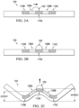
FIG. 2A is a simplified cross sectional view according to an embodiment of the droplet received at the optical surface (e.g., located on the optical surface) under surface wetting control.
FIG. 2B is a cross sectional view according to an embodiment, similar to FIG. 2A, but showing movement of the droplet at the optical surface (e.g., on the optical surface) under surface wetting control.
FIG. 2C is a cross sectional view according to an embodiment, similar to FIG. 2B, but showing vibration to expel fluid from the droplet at the optical surface (e.g., on the optical surface) under surface wetting control.
FIG. 3A is a simplified perspective view according to an embodiment, similar to FIG. 2A showing the droplet received at the optical surface (e.g., located on the optical surface) under surface wetting control.
FIG. 3B is a perspective view according to an embodiment, similar to FIG. 3A, but showing movement of the droplet at the optical surface (e.g., on the optical surface) under surface wetting control.
FIG. 3C is a perspective view according to an embodiment, similar to FIG. 3B, but showing vibration to expel fluid from the droplet at the optical surface (e.g., on the optical surface) under surface wetting control.
FIG. 4A is a simplified cross sectional view according to an embodiment of second and third droplets received at the optical surface (e.g., located on the optical surface) under surface wetting control.
FIG. 4B is a cross sectional view according to an embodiment, similar to FIG. 4A, but showing movement of the second and third droplets at the optical surface under surface wetting control.
FIG. 4C is a cross sectional view according to an embodiment, similar to FIG. 4B, but showing vibration to expel fluid from the second and third droplets at the optical surface under surface wetting control.
FIG. 5A is a simplified cross sectional view according to another embodiment of the droplet received at the optical surface (e.g., located on the optical surface) under gradient control of surface wetting.
FIG. 5B is a cross sectional view according to an embodiment, similar to FIG. 5A, but showing movement of the droplet at the optical surface (e.g., on the optical surface) under gradient control of surface wetting.
FIG. 5C is a cross sectional view according to an embodiment, similar to FIG. 5B, but showing vibration to expel fluid from the droplet at the optical surface (e.g., on the optical surface) under gradient control of surface wetting.
FIG. 5D is a cross sectional view according to another embodiment, similar to FIG. 5B, but with first areas much larger than the droplet and with a second area much smaller than the droplet.
FIG. 5E is a simplified view similar to what is shown in FIG. 1 , but with first and second areas shown much smaller than the droplet.
FIG. 6A is a diagram of impedance versus frequency for an example ultrasonic transducer mechanically coupled to an example optical surface according to an embodiment.
FIG. 6B is a diagram of example droplet size reduction versus frequency according to an embodiment.
FIGS. 7A-7B show a flowchart representative of example machine readable instructions that may be executed to implement the example system to expel fluid from the droplet under surface wetting, according to an embodiment as shown in the example of FIG. 1 .
FIG. 8 is a block diagram of an example processing platform capable of executing the machine readable instructions of FIGS. 7A-7B to implement the example system to expel fluid from the droplet under surface wetting control, according to an embodiment as shown in the example of FIG. 1 .
DETAILED DESCRIPTION OF EXAMPLE EMBODIMENTS
U.S. Pat. Nos. 10,596,604 and 10,384,239 are incorporated herein by reference.
FIG. 1 is partial block diagram of a system 100 that can expel fluid (e.g. water) from a droplet 102 from an optical surface 104 using an ultrasonic transducer 106 mechanically coupled to the optical surface 104. This apparatus can expel fluid from the droplet by atomization under wettability control from the optical surface 104. For example, the ultrasonic transducer 106 can be a piezoelectric ultrasonic transducer 106 including a piezoelectric material (e.g., lead zirconate titanate PZT or niobium doped lead zirconate titanate PNZT.) Epoxy can be used for the mechanical coupling of the ultrasonic transducer 106 with the optical surface 104. The fluid droplet 102 can be disposed on the optical surface 104, and can be coupled with the ultrasonic transducer 106 through the optical surface 104. In the example of FIG. 1 , the ultrasonic transducer 106 mechanically coupled to the optical surface 104 has first and second resonant frequency bands.
A first area 108A of the optical surface 104 can have a first wettability for the fluid, and a second area 110A of the optical surface 104 can have a second wettability for the fluid. The first area 108A is shown in the example of FIG. 1 using stippling. The second area 110A is shown in the example of FIG. 1 using cross hatching.
The second wettability of the second area 110A of the optical surface 104 can be greater than the first wettability of the first area 108A of the optical surface 104. For example, a hydrophobic coating can be applied to the first area 108A, so as to limit the wettability of the first area 108A. For example, application of the hydrophobic coating to the second area 110A can be avoided, so that second wettability of the second area 110A of the optical surface 104 can be greater than the first wettability of the first area 108A.
The first area 108A and the second area 110A can have a patterned arrangement, as shown in the example of FIG. 1 . Further, the first area 108A can be a plurality of first areas 108A, 108B, 108C, 108D, 108E, 108F, 108G, 108H, 108I, 108J, 108K, 108L. The second area 110A can be a plurality of second areas 110A, 110B, 110C, 110D, 110E, 110F, 110G, 110H, 110I, 110J, 110K, 110L, 110M. A patterned arrangement of the first and second areas can be an alternating arrangement, as shown for example in FIG. 1 , in which a member of the first areas (e.g., first area 108A) can be interposed between a pair of members of the second areas (e.g., pair of second areas 110A, 110B). In the alternating arrangement shown for example in FIG. 1 , a member of the second areas (e.g., second area 110A) can be interposed between a pair of members of the first areas (e.g., pair of first areas 108A, 108B). The first area (e.g., first area 108A) and the second area (e.g., second area 110A) can be adjacent to one another in the patterned arrangement, as shown in the example of FIG. 1 . A first edge 108AE of the first area (e.g., first area 108A) can be proximate to a second edge 110AE of the second area (e.g., second area 110A) in the patterned arrangement.
Accordingly, the patterned arrangement of the first and second areas can be an alternating grid arrangement, for example a checkerboard like square grid arrangement as shown for example in FIG. 1 . In other examples the optical surface 104 can be circular. For example, the patterned arrangement of the first and second areas can be an alternating concentric circular grid arrangement. For example, rather than the checkerboard like square grid arrangement shown in the example of FIG. 1 , a dart board like concentric circular grid arrangement can be used in the patterned arrangement of the first and second areas.
As shown in the example of FIG. 1 , a signal generator 112 can be coupled with the ultrasonic transducer 106. The signal generator 112 can generate a first signal 114 including a first frequency 116 to reduce the fluid droplet from a first size 102A to a second size 102B, and to generate a second signal 118 including a second frequency 120 to reduce the fluid droplet from the second size 102B to a third size 102C. In the drawings: the first droplet size 102A is representatively illustrated using a dash-dot-dot-dash line style; the second droplet size 102B is representatively illustrated using a dash-dot-dash line style; and the third droplet size 102C is representatively illustrated using solid line style.
The first frequency 116 to reduce the fluid droplet from the first size 102A to the second size 102B can be higher in frequency than the second frequency 120 to reduce the fluid droplet from the second size 102B to the third size 102C. The first frequency 116 of the first signal 114 is within the first resonant frequency band of the ultrasonic transducer 106 mechanically coupled to the optical surface 104. In some examples, the first frequency 116 of the first signal 114 can be a first sweep of frequencies (e.g., a first frequency sweep) within the first resonant frequency band of the ultrasonic transducer 106 mechanically coupled to the optical surface 104. The second frequency 120 of the second signal 118 is within the second resonant frequency band of the ultrasonic transducer 106 mechanically coupled to the optical surface 104. In some examples, the second frequency 120 of the second signal 118 can be a second sweep of frequencies (e.g., a second frequency sweep) within the second resonant frequency band of the ultrasonic transducer 106 mechanically coupled to the optical surface 104. The first frequency 116 of the first signal 114 can be different than the second frequency 120 of the second signal 118. The first frequency sweep can be different than the second frequency sweep. The first resonant frequency band can be different than the second resonant frequency band.
As shown in the example of FIG. 1 , the first area 108A can have a first width dimension W108A that can be greater than a corresponding width W102A of the first size 102A of the droplet 102. The first width dimension W108A of the first area 108A can be greater than a corresponding width W102B of the second size 102B of the droplet 102. The first width dimension W108A of the first area 108A can be greater than a corresponding width W102C of the third size 102C of the droplet 102.
Similarly, as shown in the example of FIG. 1 , the second area 110A can have a first width dimension W110A that can be greater than a corresponding width W102A of the first size 102A of the droplet 102. The second width dimension W110A of the second area 110A can be greater than a corresponding width W102B of the second size 102B of the droplet 102. The second width dimension W110A of the second area 108A can be greater than a corresponding width W102C of the third size 102C of the droplet 102.
FIG. 2A is a simplified cross sectional view according to an embodiment of the droplet 102 received at the optical surface 104 (e.g., located on the optical surface 104) under surface wetting control. FIG. 2B is a cross sectional view according to an embodiment, similar to FIG. 2A, but showing movement of the droplet 102 at the optical surface 104 under surface wetting control. FIG. 2C is a cross sectional view according to an embodiment, similar to FIG. 2B, but showing vibration to expel fluid from the droplet 102 at the optical surface 104 under surface wetting control.
The first areas 108A, 108B are shown in the examples of FIGS. 2A-2C using stippling. The second areas 110A, 110B, 110C are shown in the examples of FIGS. 2A-2C using cross hatching. The examples of FIGS. 2A-2C show the alternating patterned arrangement in cross sectional view of the first areas (e.g., first areas 108A, 108B) and the second areas (e.g., second areas 110A, 110B, 110C). For example, a member of the first areas (e.g., first area 108A) can be interposed between a pair of members of the second areas (e.g., pair of second areas 110A, 110B). Another member of the first areas (e.g., first area 108B) can be interposed between another pair of members of the second areas (e.g., pair of second areas 110A, 110C). A member of the second areas (e.g., second area 110A) can be interposed between a pair of members of the first areas (e.g., pair of first areas 108A, 108B).
In the examples of FIGS. 2A-2C, the second wettability of the second areas 110A, 110B, 110C of the optical surface 104 can be greater than the first wettability of the first areas 108A, 108B of the optical surface 104. For example, the hydrophobic coating can be applied to the first areas 108A, 108B so as to limit the wettability of the first areas 108A, 108B. For example, application of the hydrophobic coating to the second areas 110A, 110B, 110C can be avoided, so that second wettability of the second areas 110A, 110B, 110C of the optical surface 104 can be greater than the first wettability of the first areas 108A, 108B.
The second wettability of the second areas 110A, 110B, 110C of the optical surface 104 is sufficiently greater than the first wettability of the first areas 108A, 108B of the optical surface 104 to cause at least some movement of the droplet 102 from the first area 108A to the second area 110A. FIG. 2A shows droplet 102 partially received at (e.g., partially located on) the first area 108A having the first wettability and partially received at (e.g., partially located on) the second area 110A having the second wettability. Since the second wettability is greater than the first wettability, a notional block arrow is shown in FIG. 2A to depict movement of the droplet 102 from the first area 108A to the second area 110 A. Further, comparison of FIG. 2A to FIG. 2B shows that in FIG. 2B the droplet has moved to the second area 110A, from being partially received at (e.g., partially located on) the first area 108A and partially received at (e.g., partially located on) the second area 110A in FIG. 2A.
The ultrasonic transducer 106 described above with respect to FIG. 1 can excite a vibrational mode of the optical surface 104 having a greater extent of vibration at the second area 110A than at the first area 108A. For example, FIG. 2C shows the vibrational mode of the optical surface 104 having a first extent of vibration (e.g., EXTENT1) at the first area 108A and having a second extent of vibration (e.g., EXTENT2) at the second area 110A. As shown in the example of FIG. 2C, the second extent of vibration (e.g., EXTENT2) at the second area 110A is greater than the first extent of vibration (e.g., EXTENT1) at the first area 108A. For example, the relatively greater wettability of the second area 110A can move the droplet 102, where the relatively greater extent of vibration (e.g., EXTENT2) can expel fluid from the droplet by atomization. For example, regions of greatest wettability (e.g. second area 110A) can be placed at locations of largest vibration amplitude. In the example of FIG. 2C, a notional upward block arrow is used to depict the relatively greater extent of vibration (e.g., EXTENT2) expelling fluid from the droplet 102 by atomization.
FIG. 3A is a simplified perspective view according to an embodiment, similar to FIG. 2A showing the droplet 102 received at the optical surface 104 (e.g., located on the optical surface 104) under surface wetting control. FIG. 3B is a perspective view according to an embodiment, similar to FIG. 3A, but showing movement of the droplet 102 at the optical surface 104 under surface wetting control. FIG. 3C is a perspective view according to an embodiment, similar to FIG. 3B, but showing vibration to expel fluid from the droplet 102 at the optical surface 104 under surface wetting control. The first areas are shown in the examples of FIGS. 3A-3B using stippling. The second areas are shown in the examples of FIGS. 3A-3B using cross hatching. The examples of FIGS. 3A-3B show the alternating patterned arrangement in perspective view of the first areas and the second areas.
The second wettability of the second area 110A of the optical surface 104 is sufficiently greater than the first wettability of the first area 108A of the optical surface 104 to cause at least some movement of the droplet 102 from the first area 108A to the second area 110A. FIG. 3A shows droplet 102 partially received at (e.g., partially located on) the first area 108A having the first wettability and partially received at (e.g., partially located on) the second area 110A having the second wettability. Since the second wettability is greater than the first wettability, a notional block arrow is shown in FIG. 3A to depict movement of the droplet 102 from the first area 108A to the second area 110 A. Further, comparison of FIG. 3A to FIG. 3B shows that in FIG. 3B the droplet has moved to the second area 110A, from being partially received at (e.g., partially located on) the first area 108A and partially received at (e.g., partially located on) the second area 110A in FIG. 3A.
For example, the relatively greater wettability of the second area 110A can move the droplet 102, where the relatively greater extent of vibration can expel fluid from the droplet by atomization. In the example of FIG. 3C, a notional upward block arrow is used to depict the relatively greater extent of vibration expelling fluid from the droplet 102 by atomization. For ease of viewing, depiction of vibration is simplified in FIG. 3C, and both the second area 110A and the droplet 102 are depicted using a stippled line style.
While a droplet 102 is shown, and described above with respect to FIG. 1 , FIGS. 2A-2C, and FIGS. 3A-3B, the foregoing is likewise applicable to additional droplets, for example, a second droplet and a third droplet. FIG. 4A is a simplified cross sectional view according to an embodiment of a second droplet 122 and a third droplet 124 received at the optical surface 104 (e.g., located on the optical surface 104) under surface wetting control. FIG. 4B is a cross sectional view according to an embodiment, similar to FIG. 4A, but showing movement of the second droplet 122 and the third droplet 124 at the optical surface 104 under surface wetting control. FIG. 4C is a cross sectional view according to an embodiment, similar to FIG. 4B, but showing vibration to expel fluid from the second droplet 122 and the third droplet 124 at the optical surface 104 under surface wetting control.
In the examples of FIGS. 4A-4C, the second wettability of the second areas 110A, 110B, 110C of the optical surface 104 can be greater than the first wettability of the first areas 108A, 108B of the optical surface 104. For example, the second wettability of the second areas 110B, 110C of the optical surface 104 is sufficiently greater than the first wettability of the first areas 108A, 108B of the optical surface to cause at least some movement of the second and third droplets 122, 124 from the first areas 108A, 108B to the second areas 110B, 110C. The example of FIG. 4A shows second droplet 122 partially received at (e.g., partially located on) one of the first areas 108A having the first wettability and partially received at (e.g., partially located on) one the second areas 110B having the second wettability. Similarly, the example of FIG. 4A also shows third droplet 124 partially received at (e.g., partially located on) another one of the first areas 108B having the first wettability and partially received at (e.g., partially located on) another one the second areas 110C having the second wettability. Since the second wettability is greater than the first wettability, notional block arrows are shown in FIG. 4A to depict movement of the second droplet 122 from the one of the first areas 108A to one of the second areas 110 B, and to depict movement of the third droplet 124 from another one of the first areas 108B to another one of the second areas 110C. Further, comparison of FIG. 4A to FIG. 4B shows that in FIG. 4B the second droplet 122 has moved to the one of the second areas 110B, from being partially received at (e.g., partially located on) one of the first areas 108A and partially received at (e.g., partially located on) the one of the second areas 110B in FIG. 4A. In FIG. 4B the third droplet 124 has moved to another one of the second areas 110C, from being partially received at (e.g., partially located on) another one of the first areas 108B and partially received at (e.g., partially located on) another one of the second areas 110C in FIG. 4A.
For example, FIG. 4C shows the vibrational mode of the optical surface 104 having a first extent of vibration (e.g., EXTENT1) at first areas 108A, 108B and having a second extent of vibration (e.g., EXTENT2) at one and another one of the second areas 110B, 110C. As shown in the example of FIG. 4C, the second extent of vibration (e.g., EXTENT2) at one and another one of the second areas 110B, 110C is greater than the first extent of vibration (e.g., EXTENT1) at the first areas 108A, 108B. For example, the relatively greater wettability of one and another one of the second areas 110B, 110C can move the second and third droplets 122, 124, where the relatively greater extent of vibration (e.g., EXTENT2) can expel fluid from the droplet by atomization. For example, regions of greatest wettability (e.g. second areas 110B, 110C) can be placed at locations of largest vibration amplitude. In the example of FIG. 4C, notional upward block arrows are used to depict the relatively greater extent of vibration (e.g., EXTENT2) expelling fluid from the second and third droplets 122, 124 by atomization. An added benefit is when droplets that are smaller than a given region fall onto the surface, they will still tend migrate to the locations of largest vibration amplitude due to an acceleration gradient across the droplet.
FIG. 5A is a simplified cross sectional view according to another embodiment of the droplet 502 received at the optical surface 504 (e.g., located on the optical surface 504) under gradient control of surface wetting. FIG. 5B is a cross sectional view according to an embodiment, similar to FIG. 5A, but showing movement of the droplet 502 at the optical surface 504 under gradient control of surface wetting. FIG. 5C is a cross sectional view according to an embodiment, similar to FIG. 5B, but showing vibration to expel fluid from the droplet 502 at the optical surface 504 under gradient control of surface wetting.
A first area 508A having an increasing gradient of wettability in a direction towards second area 510A is shown in the examples of FIGS. 5A-5C using an increasingly darkened gradient depiction in the direction towards second area 510A. Similarly, additional first area 508B having an increasing gradient of wettability in an additional direction towards second area 510A is shown in the examples of FIGS. 5A-5C using an increasingly darkened gradient depiction in the additional direction towards second area 510A. The second area 510A is shown in the examples of FIGS. 5A-5C using cross hatching. The examples of FIGS. 5A-5C show the increasing wettability gradient patterned arrangement in cross sectional view of the first areas (e.g., first areas 508A, 508B) and the second area (e.g., second area 510A). For example, a second area 510A can be interposed between a pair of members of the first areas (e.g., pair of first areas 508A, 508B). For example, second area 510A can be centrally arranged between first area 508A and additional first area 508B. For example, the first area 508A can have an increasing gradient of wettability in a centrally oriented direction towards second area 510A, as shown in the examples of FIGS. 5A-5C using an increasingly darkened gradient depiction in the centrally oriented direction towards second area 510A. Similarly, additional first area 508B can have an increasing gradient of wettability in an additional centrally oriented direction towards second area 510A as shown in the examples of FIGS. 5A-5C using an increasingly darkened gradient depiction in the additional centrally oriented direction towards second area 510A. For example, the optical surface 504 can have a wettability gradient that increases (e.g. increases monotonically) from peripheral areas of the optical surface 504 (e.g., first area 508A and additional first area 508B) towards a central area of the optical surface 504 (e.g., second area 510A).
In the examples of FIGS. 5A-5C, the second wettability of the second area 510A of the optical surface 504 can be greater than the first gradient wettability of the first areas 508A, 508B of the optical surface 504. For example, the hydrophobic coating can be applied in a suitable gradient manner, for example using inkjet printing, to the first areas 508A, 508B so as to limit the wettability of the first areas 508A, 508B in a gradient manner. For example, application of the hydrophobic coating to the second area 510A can be avoided, so that second wettability of the second area 510A of the optical surface 504 can be greater than the first gradient wettability of the first areas 508A, 508B.
The second wettability of the second area 510A of the optical surface 504 is sufficiently greater than the first gradient wettability of the first areas 508A, 508B of the optical surface 504 to cause at least some movement of the droplet 502 from the first area 508A to the second area 510A. FIG. 5A shows droplet 502 partially received at (e.g., partially located on) the first area 508A having the first gradient wettability and partially received at (e.g., partially located on) the second area 510A having the second wettability. Since the second wettability is greater than the first gradient wettability, a notional block arrow is shown in FIG. 5A to depict movement of the droplet 502 from the first area 508A to the second area 510 A. Further, comparison of FIG. 5A to FIG. 5B shows that in FIG. 5B the droplet has moved to the second area 510A, from being partially received at (e.g., partially located on) the first area 508A and partially received at (e.g., partially located on) the second area 510A in FIG. 5A. For example, since the optical surface 504 can have a wettability gradient that increases (e.g. increases monotonically) from peripheral areas of the optical surface 504 (e.g., first area 508A and additional first area 508B) towards a central area of the optical surface 504 (e.g., second area 510A), the droplet 502 can be moved thereby from peripheral areas of the optical surface 504 (e.g., from first area 508A) towards the central area of the optical surface 504 (e.g., towards second area 510A).
The ultrasonic transducer 106 described above with respect to FIG. 1 can excite a vibrational mode of the optical surface 504 having a greater extent of vibration at the second area 510A than at the first area 508A. For example, FIG. 5C shows the vibrational mode of the optical surface 504 having a first extent of vibration (e.g., EXTENT1) at the first area 508A and having a second extent of vibration (e.g., EXTENT2) at the second area 510A. As shown in the example of FIG. 5C, the second extent of vibration (e.g., EXTENT2) at the second area 510A is greater than the first extent of vibration (e.g., EXTENT1) at the first area 508A. For example, the relatively greater wettability of the second area 510A can move the droplet 502, where the relatively greater extent of vibration (e.g., EXTENT2) can expel fluid from the droplet by atomization. For example, regions of greatest wettability (e.g. second area 510A) can be placed (e.g., centrally placed) at locations of largest vibration amplitude. In the example of FIG. 5C, a notional upward block arrow is used to depict the relatively greater extent of vibration (e.g., EXTENT2) expelling fluid from the droplet 502 by atomization.
FIG. 5D is a cross sectional view according to another embodiment, similar to FIG. 5B, but with first areas 508A, 508B much larger than the droplet 502 and with a second area 510A much smaller than the droplet 502. In some examples, the second area 510A can be an order of magnitude smaller than the droplet 502 (e.g., at least an order of magnitude smaller than the droplet 502, or even smaller). In the example of FIG. 5D, the first area 508A can have the increasing gradient of wettability in the centrally oriented direction towards second area 510A, as shown in FIG. 5D using the increasingly darkened gradient depiction in the centrally oriented direction towards second area 510A. Similarly, additional first area 508B can have the increasing gradient of wettability in the additional centrally oriented direction towards second area 510A as shown in FIG. 5D using the increasingly darkened gradient depiction in the additional centrally oriented direction towards second area 510A. For example, the optical surface 504 shown in FIG. 5D can have the wettability gradient that increases (e.g. increases monotonically) from peripheral areas of the optical surface 504 (e.g., first area 508A and additional first area 508B) towards the central area of the optical surface 504 (e.g., second area 510A).
In additional other examples, the first areas and/or second areas can be smaller than the droplet (e.g., an order of magnitude smaller than the droplet, e.g., at least an order of magnitude smaller than the droplet, or smaller). In some examples, respective members of the first areas 108A, 108B, 108C, 108D, 108E, 108F, 108G, 108H, 108I, 108J, 108K, 108L shown in FIG. 1 can be smaller than the droplet 102 (e.g., an order of magnitude smaller than the droplet, e.g., at least an order of magnitude smaller than the droplet, or smaller). In some examples, respective members of the second areas 110A, 110B, 110C, 110D, 110E, 110F, 110G, 110H, 110I, 110J, 110K, 110L, 110M can be smaller than the droplet 102 (e.g., an order of magnitude smaller than the droplet, e.g., at least an order of magnitude smaller than the droplet, or smaller).
FIG. 5E is a simplified view similar to what is shown in FIG. 1 , but with first areas 508A, 508B, 508C, 508D, 508E, 508F, 508G, 508H, 508I, 508J, 508K, 508L and second areas 510A, 510B, 510C, 510D, 510E, 510F, 510G, 510H, 510I, 510J, 510K, 510L, 510M shown much smaller than the droplet 502 on optical surface 504. Second wettability of the second areas of the optical surface 504 can be greater than the first wettability of the first areas. The first areas are shown in the example of FIG. 5E using stippling. The second areas are shown in the example of FIG. 5E using cross hatching.
FIG. 6A is a diagram 600 a of impedance (Ohms in decibels) versus frequency (logarithmic scale in kilohertz) for an example ultrasonic transducer mechanically coupled to an example optical surface according to an embodiment. FIG. 6A shows the example first frequency of three-hundred kilohertz for the example ultrasonic transducer mechanically coupled to the example optical surface. The example first frequency of the example three-hundred kilohertz can correspond to a first nominal resonance frequency of a first low impedance resonance extremity 602 in the diagram of FIG. 6A at the first frequency of the example ultrasonic transducer mechanically coupled to the example optical surface. The example first frequency of three-hundred kilohertz can correspond to the first nominal resonance frequency of the first low impedance resonance extremity 602 that is centered within a first resonance band “602band”. More broadly, the first frequency is within a first resonance band “602band”. The first resonance band is defined herein as extending in frequency to plus and minus ten percent of the first nominal resonance frequency of the first low impedance resonance extremity for the ultrasonic transducer mechanically coupled to the optical surface. For example, with the example first frequency of three-hundred kilohertz, the first resonance band extends in frequency to plus and minus ten percent of the first nominal resonance frequency of three-hundred kilohertz (e.g. the first resonance band extends in frequency to plus and minus thirty kilohertz from the three-hundred kilohertz, or the first resonance band extends in frequency from two-hundred-and-seventy kilohertz to three-hundred-and-thirty kilohertz).
Further, FIG. 6A shows the example second frequency of twenty-six kilohertz for the example ultrasonic transducer mechanically coupled to the example optical surface. The example second frequency of twenty-six kilohertz corresponds to a second nominal resonance frequency of a second low impedance resonance extremity 604 in the diagram of FIG. 6A at the second frequency of the example ultrasonic transducer mechanically coupled to the example optical surface. The example second frequency of twenty-six kilohertz corresponds to the second nominal resonance frequency of the second low impedance resonance extremity 604 that is centered within a second resonance band “604band”. More broadly, the second frequency is within a second resonance band “604band”. The second resonance band is defined herein as extending in frequency to plus and minus ten percent of the second nominal resonance frequency of the second low impedance resonance extremity for the ultrasonic transducer mechanically coupled to the optical surface. For example, with the example second frequency of twenty-six kilohertz, the second resonance band extends in frequency to plus and minus ten percent of the second nominal resonance frequency of twenty-six kilohertz (e.g. the second resonance band extends in frequency to plus and minus two and six-tenths kilohertz from the twenty-six kilohertz, or the second resonance band extends in frequency from twenty-three-and-four-tenths kilohertz to twenty-eight-and-six-tenths kilohertz).
FIG. 6B is a diagram 600 b of example droplet size reduction versus frequency according to an embodiment. The example of FIG. 6B shows the example first frequency of the example three-hundred kilohertz for the example ultrasonic transducer mechanically coupled to the example optical surface. As shown in the example of FIG. 6B, the example first frequency 602 of the example three-hundred kilohertz can reduce the droplet from the first droplet size 606 (e.g., reduce from ten millimeters in droplet diameter) to the second droplet size 608 (e.g., reduce to four millimeters in droplet diameter). Further, the example of FIG. 6B shows the example second frequency 604 of twenty-six kilohertz for the example ultrasonic transducer mechanically coupled to the example optical surface. As shown in the example of FIG. 6B, the example second frequency 604 of twenty-six kilohertz can reduce the droplet from the second droplet size 608 (e.g., reduce from four millimeters in droplet diameter) to the third droplet size 610 (e.g., reduce to eight-tenths of a millimeter in droplet diameter).
While example manners of implementing the example system 100 for expelling fluid from a droplet 102 from an optical surface 104 using the ultrasonic transducer 106 mechanically coupled to the optical surface 104 under wettability control as in FIG. 1 , one or more of the elements, processes and/or devices illustrated in FIG. 1 may be combined, divided, re-arranged, omitted, eliminated and/or implemented in any other way.
Further, the example system 100, example optical surface 104, 504, example ultrasonic transducer 106, example first areas 108A, 108B, 108C, 108D, 108E, 108F, 108G, 108H, 108I, 108J, 108K, 108L, 508A, example second areas 110A, 110B, 110C, 110D, 110E, 110F, 110G, 110H, 110I, 110J, 110K, 110L, 110M, 510A, 510B, example edge of the first area 108AE, example edge of second area 110AE, example signal generator 112, example first signal 114, example first frequency 116, example second signal 118, example second frequency 120, example width of first area W108A, example width of second area W110A, example first extent of vibration EXTENT1, example second extent of vibration EXTENT2, example first low impedance resonance extremity 602, example first resonance band 602band, example second low impedance resonance extremity 604, and example second resonance band 604band of the example of FIG. 1 may be implemented by hardware, software, firmware and/or any combination of hardware, software and/or firmware, and may be implemented by one or more analog or digital circuit(s), logic circuits, programmable processor(s), application specific integrated circuit(s) (ASIC(s)), programmable logic device(s) (PLD(s)) and/or field programmable logic device(s) (FPLD(s)).
Further still, the example system 100, example optical surface 104, 504, example ultrasonic transducer 106, example first areas 108A, 108B, 108C, 108D, 108E, 108F, 108G, 108H, 108I, 108J, 108K, 108L, 508A, example second areas 110A, 110B, 110C, 110D, 110E, 110F, 110G, 110H, 110I, 110J, 110K, 110L, 110M, 510A, 510B, example edge of the first area 108AE, example edge of second area 110AE, example signal generator 112, example first signal 114, example first frequency 116, example second signal 118, example second frequency 120, example width of first area W108A, example width of second area W110A, example first extent of vibration EXTENT1, example second extent of vibration EXTENT2, example first low impedance resonance extremity 602, example first resonance band 602band, example second low impedance resonance extremity 604, and example second resonance band 604band of the example of FIG. 1 may include one or more elements, processes and/or devices in addition to, or instead of, those illustrated in FIG. 1 , and/or may include more than one of any or all of the illustrated elements, processes and devices.
When reading any of the apparatus or system claims of this patent to cover a purely software and/or firmware implementation, at least one of the example system 100, example optical surface 104, 504, example ultrasonic transducer 106, example first areas 108A, 108B, 108C, 108D, 108E, 108F, 108G, 108H, 108I, 108J, 108K, 108L, 508A, example second areas 110A, 110B, 110C, 110D, 110E, 110F, 110G, 110H, 110I, 110J, 110K, 110L, 110M, 510A, 510B, example edge of the first area 108AE, example edge of second area 110AE, example signal generator 112, example first signal 114, example first frequency 116, example second signal 118, example second frequency 120, example width of first area W108A, example width of second area W110A, example first extent of vibration EXTENT1, example second extent of vibration EXTENT2, example first low impedance resonance extremity 602, example first resonance band 602band, example second low impedance resonance extremity 604, and example second resonance band 604band of the example of FIG. 1 is/are hereby expressly defined to include a tangible computer readable storage device or storage disk such as a memory, a digital versatile disk (DVD), a compact disk (CD), a Blu-ray disk, etc. storing the software and/or firmware.
FIGS. 7A-7B show a flowchart representative of example machine readable instructions that may be executed to implement the example system 100 to expel fluid from the droplet 102 on the optical surface 104 under wettability control, according to an embodiment as shown in the example of FIG. 1 . In this example, the machine readable instructions comprise a program for execution by a processor, such as the processor 812 shown in the example processor platform 800 described below in connection with FIG. 8 . The program may be embodied in software stored on a tangible computer readable storage medium such as a CD-ROM, a floppy disk, a hard drive, a digital versatile disk (DVD), a Blu-ray disk, or a memory associated with the processor 812, but the entire program and/or parts thereof could alternatively be executed by a device other than the processor 812 and/or embodied in firmware or dedicated hardware. Further, although the example program is described with reference to the flowchart illustrated in FIGS. 7A-7B, many other methods of implementing the example system 100 to expel fluid from the droplet 102 on the optical surface 104 under wettability control may alternatively be used. For example, the order of execution of the blocks may be changed, and/or some of the blocks described may be changed, eliminated, or combined.
As described above, the example processes of FIGS. 7A-7B may be implemented using coded instructions (e.g., computer and/or machine readable instructions) stored on a tangible computer readable storage medium such as a hard disk drive, a flash memory, a read-only memory (ROM), a compact disk (CD), a digital versatile disk (DVD), a cache, a random-access memory (RAM) and/or any other storage device or storage disk in which information is stored for any duration (e.g., for extended time periods, permanently, for brief instances, for temporarily buffering, and/or for caching of the information). As used herein, the term tangible computer readable storage medium is expressly defined to include any type of computer readable storage device and/or storage disk and to exclude propagating signals and to exclude transmission media. As used herein, “tangible computer readable storage medium” and “tangible machine readable storage medium” are used interchangeably. In some examples, the example processes of FIGS. 7A-7B may be implemented using coded instructions (e.g., computer and/or machine readable instructions) stored on a non-transitory computer and/or machine readable medium such as a hard disk drive, a flash memory, a read-only memory, a compact disk, a digital versatile disk, a cache, a random-access memory and/or any other storage device or storage disk in which information is stored for any duration (e.g., for extended time periods, permanently, for brief instances, for temporarily buffering, and/or for caching of the information). As used herein, the term non-transitory computer readable medium is expressly defined to include any type of computer readable storage device and/or storage disk and to exclude propagating signals and to exclude transmission media.
A process flow 700 of FIGS. 7A-7B can begin at block 702. At block 702, the optical surface can receive the first size of the droplet to overlap a first area of the optical surface and a second area of the surface. The first area can have a first wettability for a fluid of the droplet. The second area of the surface can have a second wettability for the fluid, in which the first wettability of the first area of the surface is greater than the second wettability of the second area of the surface. For example, FIG. 2A shows optical surface 104 to receive the first size of the droplet 102 to overlap the first area 108A of the optical surface 104 and the second area 110A of the optical surface 104.
Next, as shown in the example of FIG. 7A, at block 704 there can be at least some movement of the droplet from the first area of the surface to the second area of the surface based on the first wettability of the first area of the surface being greater than the second wettability of the second area of the surface. For example, since the second wettability is greater than the first wettability, a notional block arrow is shown in FIG. 2A to depict movement of the droplet 102 from the first area 108A to the second area 110 A. Further, comparison of FIG. 2A to FIG. 2B shows that in FIG. 2B the droplet has moved to the second area 110A, from being partially received at (e.g., partially located on) the first area 108A and partially received at (e.g., partially located on) the second area 110A in FIG. 2A.
Next, as shown in the example of FIG. 7A, at block 706 the first signal including the first frequency can be generated. For example, the signal generator 112 shown in the example of FIG. 1 can be used to generate the first signal 114 having the first frequency 116. As shown in the example of FIG. 1 , the signal generator 112 can be coupled with the ultrasonic transducer 106. The ultrasonic transducer 106 can be mechanically coupled to the optical surface 104.
Next, as shown in the example of FIG. 7A, at block 708 the ultrasonic transducer can be activated using the first signal. As shown in the example of FIG. 1 , the signal generator 112 can be coupled with the ultrasonic transducer 106 to activate the ultrasonic transducer 106 using the first signal 114. The first frequency 116 of the first signal 114 can be within the first resonant frequency band of the ultrasonic transducer 106 mechanically coupled to the optical surface 104. In some examples, the first frequency 116 of the first signal 114 can be a first sweep of frequencies (e.g., a first frequency sweep) within the first resonant frequency band of the ultrasonic transducer 106 mechanically coupled to the optical surface 104.
Next, as shown in the example of FIG. 7A, at block 710 the first frequency can excite a vibrational mode of the optical surface having a greater extent of vibration at the second area of the optical surface than at the first area of the optical surface. For example, FIG. 2C shows the vibrational mode of the optical surface 104 having a first extent of vibration (e.g., EXTENT1) at the first area 108A and having a second extent of vibration (e.g., EXTENT2) at the second area 110A. As shown in the example of FIG. 2C, the second extent of vibration (e.g., EXTENT2) at the second area 110A is greater than the first extent of vibration (e.g., EXTENT1) at the first area 108A. For example, the relatively greater wettability of the second area 110A can move the droplet 102, where the relatively greater extent of vibration (e.g., EXTENT2) can expel fluid from the droplet by atomization.
Next, as shown in the example of FIG. 7A, at block 712 the fluid droplet can be reduced by atomization from the first size to a second size using the first signal having the first frequency. As shown in the example of FIG. 1 , fluid droplet 102 can be reduced by atomization from the first size 102A to a second size 102B using the first signal 114 having the first frequency 116.
Next, as shown in the example of FIG. 7B, at block 714 the second signal including the second frequency can be generated. Next, at block 716 the ultrasonic transducer can be activated using the second signal. The second frequency of the second signal can be within a second resonant frequency band of the ultrasonic transducer mechanically coupled to the optical surface. The second frequency of the second signal can be different than the first frequency of the first signal. The second resonant frequency band can be different than the first resonant frequency band. As shown in the example of FIG. 1 , the signal generator 112 can be coupled with the ultrasonic transducer 106 to activate the ultrasonic transducer 106 using the second signal 118.
Next, as shown in the example of FIG. 7B, at block 718 the second frequency can excite a vibrational mode of the optical surface having a greater extent of vibration at the second area of the optical surface than at the first area of the optical surface. For example, FIG. 2C shows the vibrational mode of the optical surface 104 having a first extent of vibration (e.g., EXTENT1) at the first area 108A and having a second extent of vibration (e.g., EXTENT2) at the second area 110A. As shown in the example of FIG. 2C, the second extent of vibration (e.g., EXTENT2) at the second area 110A is greater than the first extent of vibration (e.g., EXTENT1) at the first area 108A.
Next, as shown in the example of FIG. 7B, at block 720 the droplet can be reduced by atomization from the second size to a third size using the second signal having the second frequency. As shown in the example of FIG. 1 , fluid droplet 102 can be reduced by atomization from the second size 102B to a third size 102C using the second signal 118 having the second frequency 120.
Next, at decision block 722 it is determined whether to end the cycle of expelling fluid from the optical surface. For example, if a control input registered at a time determines that the cycle is not to end at that time, then flow execution transfers to block 702 shown in FIG. 7A. However, if a control input registered at that time determines that the cycle is to end at that time, then after block 722, the example method 700 can end.
FIG. 8 is a block diagram of an example processing platform capable of executing the machine readable instructions of FIGS. 8A-8B to implement the example system to expel fluid from the droplet under wettability control, according to an embodiment as shown in the example of FIG. 1 .
The processor platform 800 can be, for example, a server, a personal computer, a mobile device (e.g., a cell phone, a smart phone, a tablet such as an iPad™), a personal digital assistant (PDA), an Internet appliance, a DVD player, a CD player, a digital video recorder, a Blu-ray player, a gaming console, a personal video recorder, a set top box, or any other type of computing device.
The processor platform 800 of this example includes a processor 812. The processor 812 of this example is hardware. For example, the processor 812 can be implemented by one or more integrated circuits, logic circuits, microprocessors or controllers from any desired family or manufacturer. The hardware of processor 812 can be virtualized using virtualization such as Virtual Machines and/or containers. The processor 812 can implement example signal generator 112, including example first signal 114, example first frequency 116, example second signal 118, and example second frequency 120.
The processor 812 of this example includes a local memory 813 (e.g., a cache). The processor 812 of this example is in communication with a main memory including a volatile memory 814 and a nonvolatile memory 816 via a bus 818. The volatile memory 814 may be implemented by synchronous dynamic random access memory (SDRAM), dynamic random access memory (DRAM), RAMBUS dynamic random access memory (RDRAM) and/or any other type of random access memory device. The nonvolatile memory 816 may be implemented by flash memory and/or any other desired type of memory device. Access to the main memory 814, 816 is controlled by a memory controller.
The processor platform 800 of this example also includes an interface circuit 820. The interface circuit 820 may be implemented by any type of interface standard, such as an Ethernet interface, a universal serial bus (USB), and/or a PCI express interface.
In this example, one or more input devices 822 are connected to the interface circuit 820. The input device(s) 822 permit(s) a user to enter data and commands into the processor 812. The input device(s) can be implemented by, for example, an audio sensor, a microphone, a camera (still or video), a keyboard, a button, a mouse, a touchscreen, a track-pad, a trackball, isopoint and/or a voice recognition system.
One or more output devices 824 are also connected to the interface circuit 820 of this example. The output devices 824 can be implemented, for example, by display devices (e.g., a light emitting diode (LED), an organic light emitting diode (OLED), a liquid crystal display, a cathode ray tube display (CRT), a touchscreen, a tactile output device, a light emitting diode (LED), a printer and/or speakers). The interface circuit 820 of this example, thus, usually includes a graphics driver card, a graphics driver chip or a graphics driver processor.
The interface circuit 820 of this example also includes a communication device such as a transmitter, a receiver, a transceiver, a modem and/or network interface card to facilitate exchange of data with external machines (e.g., computing devices of any kind) via a network 826 (e.g., an Ethernet connection, a digital subscriber line (DSL), a telephone line, coaxial cable, a cellular telephone system, etc.).
The processor platform 800 of this example also includes one or more mass storage devices 828 for storing software and/or data. Examples of such mass storage devices 828 include floppy disk drives, hard drive disks, compact disk drives, Blu-ray disk drives, RAID systems, and digital versatile disk (DVD) drives.
The coded instructions 832 of FIG. 8 may be stored in the mass storage device 828, in the volatile memory 814, in the nonvolatile memory 816, and/or on a removable tangible computer readable storage medium such as a CD or DVD.
Modifications are possible in the described examples, and other implementations are possible, within the scope of the claims.

Claims (14)

What is claimed is:
1. Apparatus to expel fluid from a droplet on a surface using a transducer mechanically coupled to the surface, the apparatus comprising:
a first area of the surface having a first wettability for the fluid; and
a second area of the surface having a second wettability for the fluid, in which the second wettability of the second area of the surface is greater than the first wettability of the first area of the surface, and the first area and the second area have a patterned arrangement;
wherein the transducer is configured to excite a vibrational mode of the surface having a greater extent of vibration at the second area than at the first area.
2. The apparatus of claim 1, wherein a first edge of the first area is proximate to a second edge of the second area in the patterned arrangement.
3. The apparatus of claim 1, wherein:
the first area is a plurality of first areas;
the second area is a plurality of second areas; and
the patterned arrangement of the first and second areas is an alternating arrangement in which a member of the first areas is interposed between a pair of members of the second areas.
4. The apparatus of claim 1, wherein:
the first area is a plurality of first areas;
the second area is a plurality of second areas; and
the patterned arrangement of the first and second areas is an alternating arrangement in which a member of the second areas is interposed between a pair of members of the first areas.
5. The apparatus of claim 1, wherein the second wettability of the second area of the surface is sufficiently greater than the first wettability of the first area of the surface to cause at least some movement of the droplet from the first area to the second area.
6. Apparatus to expel fluid from a droplet on a surface using a transducer mechanically coupled to the surface, the apparatus comprising:
a first area of the surface having a first wettability for the fluid; and
a second area of the surface having a second wettability for the fluid, in which the second wettability of the second area of the surface is greater than the first wettability of the first area of the surface, and the first area and the second area have a patterned arrangement;
wherein:
the first area is a plurality of first areas;
the second area is centrally arranged between a pair of members of the first areas; and
the first areas have respective increasing gradients of wettability in respective directions centrally oriented towards the second area.
7. The apparatus of claim 6, further comprising a signal generator configured to generate a first signal having a first frequency to reduce the droplet from a first size to a second size, and to generate a second signal having a second frequency to reduce the droplet from the second size to a third size.
8. The apparatus of claim 7, wherein the first area has a first width dimension that is greater than a corresponding width of the second size of the droplet.
9. The apparatus of claim 7, wherein the second area has a second width dimension that is greater than a corresponding width of the second size of the droplet.
10. The apparatus of claim 7, wherein the first area has a first width dimension that is greater than a corresponding width of the third size of the droplet.
11. The apparatus of claim 7, wherein the second area has a second width dimension that is greater than a corresponding width of the third size of the droplet.
12. The apparatus of claim 7, wherein the first frequency is higher than the second frequency.
13. The apparatus of claim 7, wherein the first frequency is within a first resonant frequency band of the transducer, and the second frequency is within a second resonant frequency band of the transducer.
14. Apparatus to expel fluid of a droplet from a surface using a transducer mechanically coupled to the surface, the apparatus comprising:
first and second adjacent areas of the surface in which the droplet overlaps the first and second areas of the surface, and the first area has a first wettability that is greater than a second wettability of the second area; and
a signal generator configured to generate a signal having a frequency to reduce a size of the droplet;
wherein the frequency of the signal generator is to excite a vibrational mode of the surface having a greater extent of vibration at the second area than at the first area.
US17/020,625 2017-04-20 2020-09-14 Methods and apparatus for surface wetting control Active 2039-10-23 US12042829B2 (en)

Priority Applications (1)

Application Number Priority Date Filing Date Title
US17/020,625 US12042829B2 (en) 2017-04-20 2020-09-14 Methods and apparatus for surface wetting control

Applications Claiming Priority (2)

Application Number Priority Date Filing Date Title
US15/492,433 US10780467B2 (en) 2017-04-20 2017-04-20 Methods and apparatus for surface wetting control
US17/020,625 US12042829B2 (en) 2017-04-20 2020-09-14 Methods and apparatus for surface wetting control

Related Parent Applications (1)

Application Number Title Priority Date Filing Date
US15/492,433 Division US10780467B2 (en) 2017-04-20 2017-04-20 Methods and apparatus for surface wetting control

Publications (2)

Publication Number Publication Date
US20200406316A1 US20200406316A1 (en) 2020-12-31
US12042829B2 true US12042829B2 (en) 2024-07-23

Family

ID=63852591

Family Applications (2)

Application Number Title Priority Date Filing Date
US15/492,433 Active 2037-08-14 US10780467B2 (en) 2017-04-20 2017-04-20 Methods and apparatus for surface wetting control
US17/020,625 Active 2039-10-23 US12042829B2 (en) 2017-04-20 2020-09-14 Methods and apparatus for surface wetting control

Family Applications Before (1)

Application Number Title Priority Date Filing Date
US15/492,433 Active 2037-08-14 US10780467B2 (en) 2017-04-20 2017-04-20 Methods and apparatus for surface wetting control

Country Status (1)

Country Link
US (2) US10780467B2 (en)

Families Citing this family (10)

* Cited by examiner, † Cited by third party
Publication number Priority date Publication date Assignee Title
US10384239B2 (en) 2016-09-27 2019-08-20 Texas Instruments Incorporated Methods and apparatus for ultrasonic lens cleaner using configurable filter banks
US10682675B2 (en) 2016-11-01 2020-06-16 Texas Instruments Incorporated Ultrasonic lens cleaning system with impedance monitoring to detect faults or degradation
US11237387B2 (en) 2016-12-05 2022-02-01 Texas Instruments Incorporated Ultrasonic lens cleaning system with foreign material detection
US10663418B2 (en) 2017-02-03 2020-05-26 Texas Instruments Incorporated Transducer temperature sensing
US10695805B2 (en) 2017-02-03 2020-06-30 Texas Instruments Incorporated Control system for a sensor assembly
US11042026B2 (en) 2017-02-24 2021-06-22 Texas Instruments Incorporated Transducer-induced heating and cleaning
US11420238B2 (en) 2017-02-27 2022-08-23 Texas Instruments Incorporated Transducer-induced heating-facilitated cleaning
US11607704B2 (en) 2017-04-20 2023-03-21 Texas Instruments Incorporated Methods and apparatus for electrostatic control of expelled material for lens cleaners
US10780467B2 (en) 2017-04-20 2020-09-22 Texas Instruments Incorporated Methods and apparatus for surface wetting control
US10908414B2 (en) 2017-05-10 2021-02-02 Texas Instruments Incorporated Lens cleaning via electrowetting

Citations (95)

* Cited by examiner, † Cited by third party
Publication number Priority date Publication date Assignee Title
US3681626A (en) 1971-11-11 1972-08-01 Branson Instr Oscillatory circuit for ultrasonic cleaning apparatus
US4019073A (en) 1975-08-12 1977-04-19 Vladimir Sergeevich Vishnevsky Piezoelectric motor structures
US4271371A (en) 1979-09-26 1981-06-02 Kabushiki Kaisha Morita Seisakusho Driving system for an ultrasonic piezoelectric transducer
US4556467A (en) 1981-06-22 1985-12-03 Mineral Separation Corporation Apparatus for ultrasonic processing of materials
US4607652A (en) 1984-08-29 1986-08-26 Yung Simon K C Contact lens cleaning apparatus
US4654554A (en) 1984-09-05 1987-03-31 Sawafuji Dynameca Co., Ltd. Piezoelectric vibrating elements and piezoelectric electroacoustic transducers
US4691725A (en) 1985-05-13 1987-09-08 Ultramed Corporation Lens cleaner
US4710233A (en) 1984-08-20 1987-12-01 Siemens Aktiengesellschaft Method and apparatus for cleaning, disinfecting and sterilizing medical instruments
US4836684A (en) 1988-02-18 1989-06-06 Ultrasonic Power Corporation Ultrasonic cleaning apparatus with phase diversifier
US4852592A (en) 1987-08-13 1989-08-01 Digangi And Ross Apparatus for the cleaning of contact lenses
US4870982A (en) 1989-01-09 1989-10-03 Tatung Company Of America, Inc. Ultrasonic cleaning apparatus for household use
US5005016A (en) 1989-04-03 1991-04-02 U.S. Philips Corporation Hybrid phase-locked loop
US5005015A (en) 1989-08-07 1991-04-02 General Electric Company Ice detection system
US5037189A (en) 1988-02-25 1991-08-06 Aisin Seiki Kabushiki Kaisha Cleaning apparatus for a mirror
US5071776A (en) 1987-11-28 1991-12-10 Kabushiki Kaisha Toshiba Wafer processsing method for manufacturing wafers having contaminant-gettering damage on one surface
US5113116A (en) 1989-10-05 1992-05-12 Firma J. Eberspacher Circuit arrangement for accurately and effectively driving an ultrasonic transducer
US5136425A (en) 1988-06-23 1992-08-04 Aisin Seiki Kabushiki Kaisha Self-cleaning plate-shaped device including a vibrator with oscillations parallel to the plane of the plate
US5155625A (en) 1989-03-24 1992-10-13 Murakami Kaimeido Co., Ltd. Water-drop-repellent mirror including a vibration plate and heating means
US5178173A (en) 1991-08-01 1993-01-12 Robert J. Pace Ultrasonic contact lens cleaning device
US5313333A (en) 1992-12-23 1994-05-17 Estman Kodak Company Method and apparatus for combined active and passive athermalization of an optical assembly
US5706840A (en) 1995-03-03 1998-01-13 Sandia Corporation Precision cleaning apparatus and method
US5853500A (en) 1997-07-18 1998-12-29 Symetrix Corporation Method for fabricating thin films of barium strontium titanate without exposure to oxygen at high temperatures
US6064259A (en) 1998-07-24 2000-05-16 Nikon Corporation Of America High power, high performance pulse width modulation amplifier
DE10114230A1 (en) 2000-03-24 2001-10-25 Bayerische Motoren Werke Ag Detecting condensation on a surface, comprises analyzing changes in dielectric constant in stray field of capacitor
US20020139394A1 (en) 2001-04-03 2002-10-03 Barry Bronson Self-cleaning lens shield
US20030214599A1 (en) 2002-05-17 2003-11-20 Junichi Ito Optical apparatus having dust off function
US6764168B1 (en) 2002-03-01 2004-07-20 Novellus Systems, Inc. Sensor for detecting droplet characteristics
US6880402B1 (en) 1999-10-27 2005-04-19 Schlumberger Technology Corporation Deposition monitoring system
CN1821536A (en) 2005-02-18 2006-08-23 株式会社东海理化电机制作所 Electric window device
CN1821539A (en) 2006-03-31 2006-08-23 上海中伟给排水设备综合服务有限公司 Anti-flood water blocking plate
US20060203342A1 (en) * 2005-03-09 2006-09-14 Chin-Yuan Chen Changeable mirror surface
US20060285108A1 (en) 2005-06-17 2006-12-21 Perkinelmer, Inc. Optical emission device with boost device
WO2007005852A2 (en) 2005-06-30 2007-01-11 Insound Medical, Inc. Hearing aid microphone protective barrier
US20070046143A1 (en) 2004-02-03 2007-03-01 Blandino Thomas P Drive Circuits and Methods for Ultrasonic Piezoelectric Actuators
US20070103554A1 (en) 2005-11-07 2007-05-10 Canon Kabushiki Kaisha Image pickup apparatus with foreign object removal capabilities
US20070159422A1 (en) 2004-02-03 2007-07-12 Blandino Thomas P Active material and light emitting device
CN101063830A (en) 2006-04-28 2007-10-31 Asml荷兰有限公司 Methods to clean a surface, a device manufacturing method, a cleaning assembly, cleaning apparatus, and lithographic apparatus
US20080198458A1 (en) 2007-02-20 2008-08-21 Canon Kabushiki Kaisha Image capturing apparatus
CN101274326A (en) 2007-03-29 2008-10-01 鸿富锦精密工业(深圳)有限公司 Optical lens surface dust removal device and dust removal method
US20080248416A1 (en) 2007-04-05 2008-10-09 Ricoh Company Ltd Toner preparation method and apparatus, and toner prepared thereby
US20090026883A1 (en) 2006-02-08 2009-01-29 Nathan James Croft Controller for a High Frequency Agitation Source
CN201223863Y (en) 2007-09-30 2009-04-22 南开大学 Narrow pulsewidth laser automatic spotter
JP2009283069A (en) 2008-05-22 2009-12-03 Kenwood Corp Optical disk device, cleaning method, and program
US7705519B2 (en) 2004-06-15 2010-04-27 Kabushiki Kaisha Toshiba Acoustic backing composition, ultrasonic probe and ultrasonic diagnostic apparatus
US7705517B1 (en) 2008-10-30 2010-04-27 Texas Instruments Incorporated Ultrasound transmitter
US20100165170A1 (en) 2008-12-26 2010-07-01 Sumio Kawai Vibrating device and image equipment having the same
US20100171872A1 (en) 2008-11-13 2010-07-08 Nikon Corporation Optical device, imaging device, and method for manufacturing optical device
CN201579230U (en) 2009-10-23 2010-09-15 河北先河环保科技股份有限公司 Minitype ultrasonic cleaning device of underwater optical measurement analysis meter
WO2010104867A1 (en) 2009-03-09 2010-09-16 Univenture Method and apparatus for separating particles from a liquid
US20110073142A1 (en) 2009-09-29 2011-03-31 Denso Corporation On-board optical sensor cover and on-board optical apparatus
US20110228389A1 (en) 2010-03-16 2011-09-22 Canon Kabushiki Kaisha Vibrator driving method, vibrating apparatus, driving apparatus having vibrating apparatus, foreign substance removing apparatus having vibrating apparatus, and optical apparatus having vibrating apparatus
US20120224309A1 (en) 2011-03-04 2012-09-06 Yazaki Corporation Power source circuit shut off apparatus
US8293026B1 (en) 2009-04-28 2012-10-23 Integrated Medical Systems International, Inc. Fixtures for the cleaning of lenses
US8337760B2 (en) 2005-07-15 2012-12-25 Pepsico, Inc. Resonant frequency bottle sanitation
US20130170685A1 (en) 2011-12-28 2013-07-04 Samsung Electronics Co., Ltd. Electronic apparatus having resonance structure for speaker device
CN103191886A (en) 2013-03-21 2013-07-10 安徽师范大学 Method for detecting surface pollution degree through ultrasonic wave and cleaning pollution
CN103312948A (en) 2012-03-12 2013-09-18 华晶科技股份有限公司 Camera device and vibration dust removal method thereof
US20130242481A1 (en) 2012-03-13 2013-09-19 Samsung Electronics Co. Ltd. Waterproof case for portable terminal
CN103376612A (en) 2012-04-18 2013-10-30 华晶科技股份有限公司 Dust removal system, camera device and vibration dust removal method thereof
US20130333978A1 (en) 2011-03-03 2013-12-19 Nitto Denko Corporation Waterproof sound-transmitting membrane and electrical product
US20140033454A1 (en) 2012-08-02 2014-02-06 Gentex Corporation Amplified piezoelectric camera lens cleaner
DE102012214650A1 (en) 2012-08-17 2014-02-20 Robert Bosch Gmbh Device for removing deposits on optical element i.e. entry lens, has data processing device coupled to sensor and actuator to actuate actuator according to specified operation strategy to remove deposits on optical element
CN103775869A (en) 2012-10-18 2014-05-07 索尼公司 Light source apparatus and image display apparatus
US20140218877A1 (en) 2013-02-01 2014-08-07 Cho-Yi Lin Electronic device and dust cover thereof
US20140253150A1 (en) 2013-03-06 2014-09-11 Apple Inc. Electronic Device With Liquid Contact Sensors
US8899761B2 (en) 2011-03-23 2014-12-02 Gentex Corporation Lens cleaning apparatus
EP2873572A1 (en) 2012-07-11 2015-05-20 Nissan Motor Co., Ltd. Vehicle-mounted-camera cleaning device, and vehicle-mounted-camera cleaning method
US9070856B1 (en) 2007-06-14 2015-06-30 Misonix, Incorporated Waveform generator for driving electromechanical device
US9084053B2 (en) 2013-01-11 2015-07-14 Red Tail Hawk Corporation Microphone environmental protection device
US9080961B2 (en) 2010-10-06 2015-07-14 Nakamura Kagakukogyo Co., Ltd. Method for detecting water in plastics and water removal system for plastic materials
US9095882B2 (en) 2011-10-20 2015-08-04 Canon Kabushiki Kaisha Piezoelectric device, dust removing apparatus, and imaging apparatus
US20150277100A1 (en) 2014-03-25 2015-10-01 Amazon Technologies, Inc. Electrowetting Display Pixel Architecture
EP2777579B1 (en) 2013-03-11 2015-11-04 Covidien LP Systems for detecting abnormalities within a circuit of an electrosurgical generator
US9226076B2 (en) 2014-04-30 2015-12-29 Apple Inc. Evacuation of liquid from acoustic space
US9253297B2 (en) 2009-09-04 2016-02-02 Nitto Denko Corporation Sound-transmitting membrane for microphone, sound-transmitting membrane member for microphone provided with the membrane, microphone, and electronic device provided with microphone
US20160178898A1 (en) 2012-07-02 2016-06-23 Agricam Ab Self-cleaning camera housings, self-cleaning camera modules, and monitoring systems comprising self-cleaning camera modules
US20160266379A1 (en) 2015-03-11 2016-09-15 Texas Instruments Incorporated Ultrasonic lens cleaning system with current sensing
WO2016167110A1 (en) 2015-04-14 2016-10-20 ソニー株式会社 Illumination device and projection-type display apparatus
US9573165B2 (en) 2014-08-22 2017-02-21 Apple Inc. Hydrophobic mesh cover
US9796359B2 (en) 2012-02-23 2017-10-24 The Raymond Corporation Method and apparatus for removing and preventing lens surface contamination on a vehicle lens
US20170343458A1 (en) 2014-12-19 2017-11-30 Micro Motion, Inc. Controlling a vibration of a vibratory sensor based on a phase error
US20170361360A1 (en) 2016-06-20 2017-12-21 Texas Instruments Incorporated Ultrasonic lens cleaning with travelling wave excitation
US20170371154A1 (en) 2016-06-28 2017-12-28 Texas Instruments Incorporated Optical device housing
WO2018020701A1 (en) 2016-07-28 2018-02-01 株式会社カクイチ製作所 Nanobubble-generating nozzle and nanobubble-generating device
US20180117642A1 (en) 2016-11-01 2018-05-03 Texas Instruments Incorporated Ultrasonic lens cleaning system with impedance monitoring to detect faults or degradation
US20180239218A1 (en) 2015-12-24 2018-08-23 Murata Manufacturing Co., Ltd. Vibrating device, method for driving same, and camera
US20180264526A1 (en) 2017-03-14 2018-09-20 Lg Electronics Inc. Device for cleaning surface using electrowetting element and method for controlling the same
US20180275397A1 (en) 2015-12-07 2018-09-27 Myongji University Industry And Academia Cooperation Foundation Device and method for cleaning camera lens part
US20180304282A1 (en) 2017-04-20 2018-10-25 Texas Instruments Incorporated Methods and apparatus for electrostatic control of expelled material for lens cleaners
WO2018207041A1 (en) 2017-05-12 2018-11-15 International Business Machines Corporation Ultra-sonic self-cleaning system
US20180326462A1 (en) 2017-05-10 2018-11-15 Texas Instruments Incorporated Lens cleaning via electrowetting
US10384239B2 (en) 2016-09-27 2019-08-20 Texas Instruments Incorporated Methods and apparatus for ultrasonic lens cleaner using configurable filter banks
US20190277787A1 (en) 2016-05-18 2019-09-12 Myongji University Industry And Academia Cooperation Foundation Cleaning apparatus and method
US10780467B2 (en) 2017-04-20 2020-09-22 Texas Instruments Incorporated Methods and apparatus for surface wetting control
WO2024079595A1 (en) 2022-10-10 2024-04-18 Quantumcorrugated S.R.L. A corrugated cardboard production apparatus

Family Cites Families (2)

* Cited by examiner, † Cited by third party
Publication number Priority date Publication date Assignee Title
JPS568688A (en) 1979-07-05 1981-01-29 Nisshin Flour Milling Co Ltd Antitumor substance 1166a and its preparation
JP5725882B2 (en) 2011-01-25 2015-05-27 キヤノン株式会社 Foreign object removal unit and optical apparatus provided with the same

Patent Citations (103)

* Cited by examiner, † Cited by third party
Publication number Priority date Publication date Assignee Title
US3681626A (en) 1971-11-11 1972-08-01 Branson Instr Oscillatory circuit for ultrasonic cleaning apparatus
US4019073A (en) 1975-08-12 1977-04-19 Vladimir Sergeevich Vishnevsky Piezoelectric motor structures
US4271371A (en) 1979-09-26 1981-06-02 Kabushiki Kaisha Morita Seisakusho Driving system for an ultrasonic piezoelectric transducer
US4556467A (en) 1981-06-22 1985-12-03 Mineral Separation Corporation Apparatus for ultrasonic processing of materials
US4710233A (en) 1984-08-20 1987-12-01 Siemens Aktiengesellschaft Method and apparatus for cleaning, disinfecting and sterilizing medical instruments
US4607652A (en) 1984-08-29 1986-08-26 Yung Simon K C Contact lens cleaning apparatus
US4654554A (en) 1984-09-05 1987-03-31 Sawafuji Dynameca Co., Ltd. Piezoelectric vibrating elements and piezoelectric electroacoustic transducers
US4691725A (en) 1985-05-13 1987-09-08 Ultramed Corporation Lens cleaner
US4852592A (en) 1987-08-13 1989-08-01 Digangi And Ross Apparatus for the cleaning of contact lenses
US5071776A (en) 1987-11-28 1991-12-10 Kabushiki Kaisha Toshiba Wafer processsing method for manufacturing wafers having contaminant-gettering damage on one surface
US4836684A (en) 1988-02-18 1989-06-06 Ultrasonic Power Corporation Ultrasonic cleaning apparatus with phase diversifier
US5037189A (en) 1988-02-25 1991-08-06 Aisin Seiki Kabushiki Kaisha Cleaning apparatus for a mirror
US5136425A (en) 1988-06-23 1992-08-04 Aisin Seiki Kabushiki Kaisha Self-cleaning plate-shaped device including a vibrator with oscillations parallel to the plane of the plate
US4870982A (en) 1989-01-09 1989-10-03 Tatung Company Of America, Inc. Ultrasonic cleaning apparatus for household use
US5155625A (en) 1989-03-24 1992-10-13 Murakami Kaimeido Co., Ltd. Water-drop-repellent mirror including a vibration plate and heating means
US5005016A (en) 1989-04-03 1991-04-02 U.S. Philips Corporation Hybrid phase-locked loop
US5005015A (en) 1989-08-07 1991-04-02 General Electric Company Ice detection system
US5113116A (en) 1989-10-05 1992-05-12 Firma J. Eberspacher Circuit arrangement for accurately and effectively driving an ultrasonic transducer
US5178173A (en) 1991-08-01 1993-01-12 Robert J. Pace Ultrasonic contact lens cleaning device
US5313333A (en) 1992-12-23 1994-05-17 Estman Kodak Company Method and apparatus for combined active and passive athermalization of an optical assembly
US5706840A (en) 1995-03-03 1998-01-13 Sandia Corporation Precision cleaning apparatus and method
US5853500A (en) 1997-07-18 1998-12-29 Symetrix Corporation Method for fabricating thin films of barium strontium titanate without exposure to oxygen at high temperatures
US6064259A (en) 1998-07-24 2000-05-16 Nikon Corporation Of America High power, high performance pulse width modulation amplifier
US6880402B1 (en) 1999-10-27 2005-04-19 Schlumberger Technology Corporation Deposition monitoring system
DE10114230A1 (en) 2000-03-24 2001-10-25 Bayerische Motoren Werke Ag Detecting condensation on a surface, comprises analyzing changes in dielectric constant in stray field of capacitor
US20020139394A1 (en) 2001-04-03 2002-10-03 Barry Bronson Self-cleaning lens shield
US6607606B2 (en) 2001-04-03 2003-08-19 Hewlett-Packard Development Company, L.P. Self-cleaning lens shield
US6764168B1 (en) 2002-03-01 2004-07-20 Novellus Systems, Inc. Sensor for detecting droplet characteristics
US20030214599A1 (en) 2002-05-17 2003-11-20 Junichi Ito Optical apparatus having dust off function
US7215372B2 (en) 2002-05-17 2007-05-08 Olympus Corporation Optical apparatus having dust off function
US20070159422A1 (en) 2004-02-03 2007-07-12 Blandino Thomas P Active material and light emitting device
US20070046143A1 (en) 2004-02-03 2007-03-01 Blandino Thomas P Drive Circuits and Methods for Ultrasonic Piezoelectric Actuators
US7705519B2 (en) 2004-06-15 2010-04-27 Kabushiki Kaisha Toshiba Acoustic backing composition, ultrasonic probe and ultrasonic diagnostic apparatus
CN1821536A (en) 2005-02-18 2006-08-23 株式会社东海理化电机制作所 Electric window device
EP1703062A2 (en) 2005-02-18 2006-09-20 Kabushiki Kaisha Tokai Rika Denki Seisakusho Power window device
US20060203342A1 (en) * 2005-03-09 2006-09-14 Chin-Yuan Chen Changeable mirror surface
US20060285108A1 (en) 2005-06-17 2006-12-21 Perkinelmer, Inc. Optical emission device with boost device
WO2007005852A2 (en) 2005-06-30 2007-01-11 Insound Medical, Inc. Hearing aid microphone protective barrier
US8494200B2 (en) 2005-06-30 2013-07-23 Insound Medical, Inc. Hearing aid microphone protective barrier
US8337760B2 (en) 2005-07-15 2012-12-25 Pepsico, Inc. Resonant frequency bottle sanitation
US20070103554A1 (en) 2005-11-07 2007-05-10 Canon Kabushiki Kaisha Image pickup apparatus with foreign object removal capabilities
US20090026883A1 (en) 2006-02-08 2009-01-29 Nathan James Croft Controller for a High Frequency Agitation Source
CN1821539A (en) 2006-03-31 2006-08-23 上海中伟给排水设备综合服务有限公司 Anti-flood water blocking plate
CN101063830A (en) 2006-04-28 2007-10-31 Asml荷兰有限公司 Methods to clean a surface, a device manufacturing method, a cleaning assembly, cleaning apparatus, and lithographic apparatus
US20080198458A1 (en) 2007-02-20 2008-08-21 Canon Kabushiki Kaisha Image capturing apparatus
CN101274326A (en) 2007-03-29 2008-10-01 鸿富锦精密工业(深圳)有限公司 Optical lens surface dust removal device and dust removal method
US20080248416A1 (en) 2007-04-05 2008-10-09 Ricoh Company Ltd Toner preparation method and apparatus, and toner prepared thereby
US9070856B1 (en) 2007-06-14 2015-06-30 Misonix, Incorporated Waveform generator for driving electromechanical device
CN201223863Y (en) 2007-09-30 2009-04-22 南开大学 Narrow pulsewidth laser automatic spotter
JP2009283069A (en) 2008-05-22 2009-12-03 Kenwood Corp Optical disk device, cleaning method, and program
US7705517B1 (en) 2008-10-30 2010-04-27 Texas Instruments Incorporated Ultrasound transmitter
US20100171872A1 (en) 2008-11-13 2010-07-08 Nikon Corporation Optical device, imaging device, and method for manufacturing optical device
US20100165170A1 (en) 2008-12-26 2010-07-01 Sumio Kawai Vibrating device and image equipment having the same
WO2010104867A1 (en) 2009-03-09 2010-09-16 Univenture Method and apparatus for separating particles from a liquid
US8286801B2 (en) 2009-03-09 2012-10-16 Univenture, Inc. Method and apparatus for separating particles from a liquid
JP5608688B2 (en) 2009-03-09 2014-10-15 ユニヴェンチャー・インコーポレーテッド Method and apparatus for separating particles from a liquid
US8293026B1 (en) 2009-04-28 2012-10-23 Integrated Medical Systems International, Inc. Fixtures for the cleaning of lenses
US9253297B2 (en) 2009-09-04 2016-02-02 Nitto Denko Corporation Sound-transmitting membrane for microphone, sound-transmitting membrane member for microphone provided with the membrane, microphone, and electronic device provided with microphone
US20110073142A1 (en) 2009-09-29 2011-03-31 Denso Corporation On-board optical sensor cover and on-board optical apparatus
CN201579230U (en) 2009-10-23 2010-09-15 河北先河环保科技股份有限公司 Minitype ultrasonic cleaning device of underwater optical measurement analysis meter
US20110228389A1 (en) 2010-03-16 2011-09-22 Canon Kabushiki Kaisha Vibrator driving method, vibrating apparatus, driving apparatus having vibrating apparatus, foreign substance removing apparatus having vibrating apparatus, and optical apparatus having vibrating apparatus
US9080961B2 (en) 2010-10-06 2015-07-14 Nakamura Kagakukogyo Co., Ltd. Method for detecting water in plastics and water removal system for plastic materials
US20130333978A1 (en) 2011-03-03 2013-12-19 Nitto Denko Corporation Waterproof sound-transmitting membrane and electrical product
US20120224309A1 (en) 2011-03-04 2012-09-06 Yazaki Corporation Power source circuit shut off apparatus
US8899761B2 (en) 2011-03-23 2014-12-02 Gentex Corporation Lens cleaning apparatus
US9095882B2 (en) 2011-10-20 2015-08-04 Canon Kabushiki Kaisha Piezoelectric device, dust removing apparatus, and imaging apparatus
KR20130076250A (en) 2011-12-28 2013-07-08 삼성전자주식회사 Electronic apparatus with resonance structure for speaker
US20130170685A1 (en) 2011-12-28 2013-07-04 Samsung Electronics Co., Ltd. Electronic apparatus having resonance structure for speaker device
US9796359B2 (en) 2012-02-23 2017-10-24 The Raymond Corporation Method and apparatus for removing and preventing lens surface contamination on a vehicle lens
CN103312948A (en) 2012-03-12 2013-09-18 华晶科技股份有限公司 Camera device and vibration dust removal method thereof
US20130242481A1 (en) 2012-03-13 2013-09-19 Samsung Electronics Co. Ltd. Waterproof case for portable terminal
CN103376612A (en) 2012-04-18 2013-10-30 华晶科技股份有限公司 Dust removal system, camera device and vibration dust removal method thereof
US20160178898A1 (en) 2012-07-02 2016-06-23 Agricam Ab Self-cleaning camera housings, self-cleaning camera modules, and monitoring systems comprising self-cleaning camera modules
EP2873572A1 (en) 2012-07-11 2015-05-20 Nissan Motor Co., Ltd. Vehicle-mounted-camera cleaning device, and vehicle-mounted-camera cleaning method
US20140033454A1 (en) 2012-08-02 2014-02-06 Gentex Corporation Amplified piezoelectric camera lens cleaner
DE102012214650A1 (en) 2012-08-17 2014-02-20 Robert Bosch Gmbh Device for removing deposits on optical element i.e. entry lens, has data processing device coupled to sensor and actuator to actuate actuator according to specified operation strategy to remove deposits on optical element
CN103775869A (en) 2012-10-18 2014-05-07 索尼公司 Light source apparatus and image display apparatus
US9084053B2 (en) 2013-01-11 2015-07-14 Red Tail Hawk Corporation Microphone environmental protection device
US20140218877A1 (en) 2013-02-01 2014-08-07 Cho-Yi Lin Electronic device and dust cover thereof
US20140253150A1 (en) 2013-03-06 2014-09-11 Apple Inc. Electronic Device With Liquid Contact Sensors
EP2777579B1 (en) 2013-03-11 2015-11-04 Covidien LP Systems for detecting abnormalities within a circuit of an electrosurgical generator
CN103191886A (en) 2013-03-21 2013-07-10 安徽师范大学 Method for detecting surface pollution degree through ultrasonic wave and cleaning pollution
US20150277100A1 (en) 2014-03-25 2015-10-01 Amazon Technologies, Inc. Electrowetting Display Pixel Architecture
US9226076B2 (en) 2014-04-30 2015-12-29 Apple Inc. Evacuation of liquid from acoustic space
US9573165B2 (en) 2014-08-22 2017-02-21 Apple Inc. Hydrophobic mesh cover
US20170343458A1 (en) 2014-12-19 2017-11-30 Micro Motion, Inc. Controlling a vibration of a vibratory sensor based on a phase error
US20160266379A1 (en) 2015-03-11 2016-09-15 Texas Instruments Incorporated Ultrasonic lens cleaning system with current sensing
WO2016167110A1 (en) 2015-04-14 2016-10-20 ソニー株式会社 Illumination device and projection-type display apparatus
US20180275397A1 (en) 2015-12-07 2018-09-27 Myongji University Industry And Academia Cooperation Foundation Device and method for cleaning camera lens part
US20180239218A1 (en) 2015-12-24 2018-08-23 Murata Manufacturing Co., Ltd. Vibrating device, method for driving same, and camera
US20190277787A1 (en) 2016-05-18 2019-09-12 Myongji University Industry And Academia Cooperation Foundation Cleaning apparatus and method
US20170361360A1 (en) 2016-06-20 2017-12-21 Texas Instruments Incorporated Ultrasonic lens cleaning with travelling wave excitation
US20170371154A1 (en) 2016-06-28 2017-12-28 Texas Instruments Incorporated Optical device housing
WO2018020701A1 (en) 2016-07-28 2018-02-01 株式会社カクイチ製作所 Nanobubble-generating nozzle and nanobubble-generating device
US10384239B2 (en) 2016-09-27 2019-08-20 Texas Instruments Incorporated Methods and apparatus for ultrasonic lens cleaner using configurable filter banks
US10596604B2 (en) 2016-09-27 2020-03-24 Texas Instruments Incorporated Methods and apparatus using multistage ultrasonic lens cleaning for improved water removal
US20180117642A1 (en) 2016-11-01 2018-05-03 Texas Instruments Incorporated Ultrasonic lens cleaning system with impedance monitoring to detect faults or degradation
US20180264526A1 (en) 2017-03-14 2018-09-20 Lg Electronics Inc. Device for cleaning surface using electrowetting element and method for controlling the same
US20180304282A1 (en) 2017-04-20 2018-10-25 Texas Instruments Incorporated Methods and apparatus for electrostatic control of expelled material for lens cleaners
US10780467B2 (en) 2017-04-20 2020-09-22 Texas Instruments Incorporated Methods and apparatus for surface wetting control
US20180326462A1 (en) 2017-05-10 2018-11-15 Texas Instruments Incorporated Lens cleaning via electrowetting
WO2018207041A1 (en) 2017-05-12 2018-11-15 International Business Machines Corporation Ultra-sonic self-cleaning system
WO2024079595A1 (en) 2022-10-10 2024-04-18 Quantumcorrugated S.R.L. A corrugated cardboard production apparatus

Non-Patent Citations (27)

* Cited by examiner, † Cited by third party
Title
Brereton, "Particle Removal by Focused Ultrasound," Journal of Sound and Vibration, 1994, pp. 683-698.
CN101063830A, English Machine Translation, 29 pages.
CN101274326A, English Machine Translation, 11 pages.
CN103312948AA, English Machine Translation, 15 pages.
CN103376612A, English Machine Translation, 16 pages.
CN201223863Y, English Machine Translation, 16 pages.
CN201579230U, English Machine Translation, 11 pages.
DE10114230A1 Machine Translation (Year: 2001).
DE102012214650, English Machine Translation, 14 pages.
Extended European Search Report in corresponding 17866470.2, dated Sep. 25, 2019, 2 pages.
Extended European Search Report in corresponding 17878085.4, dated Nov. 13, 2019, 7 pages.
Gale, "Removal of Particulate Contaminants using Ultrasonics and Megasonics: A Review," Particulate Science and Technology, 2007, 16 pages.
Graff, "Wave Motion in Elastic Solids", Dover, 1991, 3 pages.
Hagedorn, et al., "Travelling Wave Ultrasonic Motors, Part I: Working Principle and Mathematical Modelling of the Stator", Journal of Sound and Vibration, 1992, 155(1), pp. 31-46.
Howard "High Speed Photography of Ultrasonic Atomization," Thesis, Brown University, May 13, 2010 (39 pages).
International Search Report for PCT/US2017/059536 dated Feb. 28, 2018, 3 pages.
International Search Report for PCT/US2017/064530 dated Apr. 5, 2018, 3 pages.
International Search Report in corresponding PCT Application No. PCT/US2018/016714, dated Jun. 21, 2018, 2 pages.
JP5608688B2, English Machine Translation, 15 pages.
Kazemi, "Substrate Cleaning using Ultrasonics/Megasonics," IEEE, 2000, 6 pages.
Lee, "Smart Self-Cleaning Cover Glass for Automotive Miniature Cameras," IEEE, 2016, 4 pages.
Office Action for Chinese Patent Application No. ;201780067964.X dated Apr. 23, 2021, 2 pages.
Office Action for Chinese Patent Application No. 201780069987.4 dated Apr. 23, 2021, 2 pages.
Partial Supplementary European Search Report for 18747814.4, dated Jan. 13, 2020, 13 pages.
TI-78189CN Chinese Office Action dated Sep. 27, 2021.
Vaseiljev, "Ultrasonic system for solar panel cleaning," Sensors and Actuators A: Physical 200 (2013) pp. 74-78.
Ziaei-Moayyed, et al. "Electrical Deflection of Polar Liquid Streams: A Misunderstood Demonstration," Journal of Chemical Education, vol. 77, No. 11, Nov. 2000 (4 pages).

Also Published As

Publication number Publication date
US20200406316A1 (en) 2020-12-31
US20180304318A1 (en) 2018-10-25
US10780467B2 (en) 2020-09-22

Similar Documents

Publication Publication Date Title
US12042829B2 (en) Methods and apparatus for surface wetting control
US11607704B2 (en) Methods and apparatus for electrostatic control of expelled material for lens cleaners
US12128459B2 (en) Multi-frequency reduction of fluid droplet
US10598890B2 (en) Lens assembly and electronic device including the same
CN108683761A (en) Sound production control method and device, electronic device and computer readable medium
CN110058676A (en) A kind of method for oscillating, electronic equipment and storage medium
CN110290283B (en) Method and device for controlling vibration and folding screen equipment
JP2017528683A (en) System and method for ultrasonic distance detection
CN108646971A (en) Screen sounding control method and device and electronic device
US12183113B2 (en) Configuration of an ultrasonic fingerprint sensor relative to a display of a device
US20180208055A1 (en) Fuel control regulator system with acoustic pliability
EP4109926B1 (en) Distributed mode loudspeaker actuator including patterned electrodes
CN110377272B (en) Method and device for realizing SDK based on TBOX
US11363187B2 (en) Focusing method and apparatus applied to terminal device, and terminal device
US10798259B2 (en) Input device and image forming apparatus
WO2022204629A1 (en) Segmented transducers for acoustic applications
CN109691134B (en) A speaker, electronic device and method for speaker arrangement
US11842559B1 (en) Application of different bias voltages to regions of an ultrasonic fingerprint sensor
EP3136587A2 (en) Vibration motor controller, and lens apparatus and image pickup apparatus that include the same
US20250287138A1 (en) Tuning spring mass resonator of loudspeaker in mobile device
US20250389573A1 (en) Liquid level sensing device
US11900710B1 (en) Personalized fingerprint sensor system parameters
EP4599598A1 (en) Passive radiator for liquid ejection
US20140348366A1 (en) Handheld Electronic Devices and Methods Involving Distributed Mode Loudspeakers
CN106055116B (en) Control method and control device

Legal Events

Date Code Title Description
FEPP Fee payment procedure

Free format text: ENTITY STATUS SET TO UNDISCOUNTED (ORIGINAL EVENT CODE: BIG.); ENTITY STATUS OF PATENT OWNER: LARGE ENTITY

STPP Information on status: patent application and granting procedure in general

Free format text: DOCKETED NEW CASE - READY FOR EXAMINATION

STPP Information on status: patent application and granting procedure in general

Free format text: NON FINAL ACTION MAILED

STPP Information on status: patent application and granting procedure in general

Free format text: RESPONSE TO NON-FINAL OFFICE ACTION ENTERED AND FORWARDED TO EXAMINER

STPP Information on status: patent application and granting procedure in general

Free format text: NOTICE OF ALLOWANCE MAILED -- APPLICATION RECEIVED IN OFFICE OF PUBLICATIONS

ZAAA Notice of allowance and fees due

Free format text: ORIGINAL CODE: NOA

ZAAB Notice of allowance mailed

Free format text: ORIGINAL CODE: MN/=.

STPP Information on status: patent application and granting procedure in general

Free format text: DOCKETED NEW CASE - READY FOR EXAMINATION

STPP Information on status: patent application and granting procedure in general

Free format text: NOTICE OF ALLOWANCE MAILED -- APPLICATION RECEIVED IN OFFICE OF PUBLICATIONS

ZAAA Notice of allowance and fees due

Free format text: ORIGINAL CODE: NOA

ZAAB Notice of allowance mailed

Free format text: ORIGINAL CODE: MN/=.

STPP Information on status: patent application and granting procedure in general

Free format text: PUBLICATIONS -- ISSUE FEE PAYMENT VERIFIED

STCF Information on status: patent grant

Free format text: PATENTED CASE