US12013550B2 - Aperture module and camera module - Google Patents
Aperture module and camera module Download PDFInfo
- Publication number
- US12013550B2 US12013550B2 US17/179,655 US202117179655A US12013550B2 US 12013550 B2 US12013550 B2 US 12013550B2 US 202117179655 A US202117179655 A US 202117179655A US 12013550 B2 US12013550 B2 US 12013550B2
- Authority
- US
- United States
- Prior art keywords
- blades
- rotating plate
- type
- disposed
- blade
- Prior art date
- Legal status (The legal status is an assumption and is not a legal conclusion. Google has not performed a legal analysis and makes no representation as to the accuracy of the status listed.)
- Active, expires
Links
- 230000008859 change Effects 0.000 claims abstract description 14
- 230000003287 optical effect Effects 0.000 claims description 86
- 238000005096 rolling process Methods 0.000 description 16
- 239000000758 substrate Substances 0.000 description 14
- 238000012937 correction Methods 0.000 description 12
- 238000000034 method Methods 0.000 description 8
- 230000004907 flux Effects 0.000 description 7
- 230000003993 interaction Effects 0.000 description 7
- 238000001514 detection method Methods 0.000 description 6
- 230000008569 process Effects 0.000 description 3
- 230000007423 decrease Effects 0.000 description 2
- 239000000696 magnetic material Substances 0.000 description 2
- 238000004519 manufacturing process Methods 0.000 description 2
- 238000013459 approach Methods 0.000 description 1
- 230000008901 benefit Effects 0.000 description 1
- 230000000295 complement effect Effects 0.000 description 1
- RKTYLMNFRDHKIL-UHFFFAOYSA-N copper;5,10,15,20-tetraphenylporphyrin-22,24-diide Chemical compound [Cu+2].C1=CC(C(=C2C=CC([N-]2)=C(C=2C=CC=CC=2)C=2C=CC(N=2)=C(C=2C=CC=CC=2)C2=CC=C3[N-]2)C=2C=CC=CC=2)=NC1=C3C1=CC=CC=C1 RKTYLMNFRDHKIL-UHFFFAOYSA-N 0.000 description 1
- 230000003247 decreasing effect Effects 0.000 description 1
- 238000013461 design Methods 0.000 description 1
- 230000006866 deterioration Effects 0.000 description 1
- 238000006073 displacement reaction Methods 0.000 description 1
- 239000000463 material Substances 0.000 description 1
- 239000002184 metal Substances 0.000 description 1
- 229910044991 metal oxide Inorganic materials 0.000 description 1
- 150000004706 metal oxides Chemical class 0.000 description 1
- 238000012986 modification Methods 0.000 description 1
- 230000004048 modification Effects 0.000 description 1
- 239000004065 semiconductor Substances 0.000 description 1
- 230000006641 stabilisation Effects 0.000 description 1
- 238000011105 stabilization Methods 0.000 description 1
Images


Classifications
-
- G—PHYSICS
- G02—OPTICS
- G02B—OPTICAL ELEMENTS, SYSTEMS OR APPARATUS
- G02B5/00—Optical elements other than lenses
- G02B5/005—Diaphragms
-
- G—PHYSICS
- G02—OPTICS
- G02B—OPTICAL ELEMENTS, SYSTEMS OR APPARATUS
- G02B27/00—Optical systems or apparatus not provided for by any of the groups G02B1/00 - G02B26/00, G02B30/00
- G02B27/64—Imaging systems using optical elements for stabilisation of the lateral and angular position of the image
- G02B27/646—Imaging systems using optical elements for stabilisation of the lateral and angular position of the image compensating for small deviations, e.g. due to vibration or shake
-
- G—PHYSICS
- G02—OPTICS
- G02B—OPTICAL ELEMENTS, SYSTEMS OR APPARATUS
- G02B7/00—Mountings, adjusting means, or light-tight connections, for optical elements
- G02B7/02—Mountings, adjusting means, or light-tight connections, for optical elements for lenses
- G02B7/021—Mountings, adjusting means, or light-tight connections, for optical elements for lenses for more than one lens
-
- G—PHYSICS
- G02—OPTICS
- G02B—OPTICAL ELEMENTS, SYSTEMS OR APPARATUS
- G02B7/00—Mountings, adjusting means, or light-tight connections, for optical elements
- G02B7/02—Mountings, adjusting means, or light-tight connections, for optical elements for lenses
- G02B7/022—Mountings, adjusting means, or light-tight connections, for optical elements for lenses lens and mount having complementary engagement means, e.g. screw/thread
-
- G—PHYSICS
- G03—PHOTOGRAPHY; CINEMATOGRAPHY; ANALOGOUS TECHNIQUES USING WAVES OTHER THAN OPTICAL WAVES; ELECTROGRAPHY; HOLOGRAPHY
- G03B—APPARATUS OR ARRANGEMENTS FOR TAKING PHOTOGRAPHS OR FOR PROJECTING OR VIEWING THEM; APPARATUS OR ARRANGEMENTS EMPLOYING ANALOGOUS TECHNIQUES USING WAVES OTHER THAN OPTICAL WAVES; ACCESSORIES THEREFOR
- G03B29/00—Combinations of cameras, projectors or photographic printing apparatus with non-photographic non-optical apparatus, e.g. clocks or weapons; Cameras having the shape of other objects
-
- G—PHYSICS
- G03—PHOTOGRAPHY; CINEMATOGRAPHY; ANALOGOUS TECHNIQUES USING WAVES OTHER THAN OPTICAL WAVES; ELECTROGRAPHY; HOLOGRAPHY
- G03B—APPARATUS OR ARRANGEMENTS FOR TAKING PHOTOGRAPHS OR FOR PROJECTING OR VIEWING THEM; APPARATUS OR ARRANGEMENTS EMPLOYING ANALOGOUS TECHNIQUES USING WAVES OTHER THAN OPTICAL WAVES; ACCESSORIES THEREFOR
- G03B30/00—Camera modules comprising integrated lens units and imaging units, specially adapted for being embedded in other devices, e.g. mobile phones or vehicles
-
- G—PHYSICS
- G03—PHOTOGRAPHY; CINEMATOGRAPHY; ANALOGOUS TECHNIQUES USING WAVES OTHER THAN OPTICAL WAVES; ELECTROGRAPHY; HOLOGRAPHY
- G03B—APPARATUS OR ARRANGEMENTS FOR TAKING PHOTOGRAPHS OR FOR PROJECTING OR VIEWING THEM; APPARATUS OR ARRANGEMENTS EMPLOYING ANALOGOUS TECHNIQUES USING WAVES OTHER THAN OPTICAL WAVES; ACCESSORIES THEREFOR
- G03B9/00—Exposure-making shutters; Diaphragms
- G03B9/02—Diaphragms
- G03B9/06—Two or more co-operating pivoted blades, e.g. iris type
-
- H—ELECTRICITY
- H04—ELECTRIC COMMUNICATION TECHNIQUE
- H04N—PICTORIAL COMMUNICATION, e.g. TELEVISION
- H04N23/00—Cameras or camera modules comprising electronic image sensors; Control thereof
- H04N23/50—Constructional details
- H04N23/55—Optical parts specially adapted for electronic image sensors; Mounting thereof
Definitions
- the following description relates to an aperture module and a camera module including the same.
- a general digital camera includes a mechanical aperture to change an amount of incident light depending on an image capturing environment, but it is difficult for a camera module used in a small product such as the portable electronic device to separately include an aperture due to structural characteristics and spatial limitations.
- a number of blades are required to implement an incident hole size of the aperture to be diverse and close to a spherical shape, and accordingly, there is a problem that a thickness of the aperture module may be increased.
- an aperture module includes: a base; a rotating plate rotatably disposed on the base; and blades configured to form an incident hole and move by rotation of the rotating plate to change a size of the incident hole, wherein the blades are disposed in an opening disposed inside the rotating plate.
- the blades and the rotating plate may be disposed at substantially a same position in an optical axis direction.
- the blades may be disposed to at least partially overlap each other in an optical axis direction.
- the blades may include a first type blade and a second type blade at least partially overlapping the first type blade in an optical axis direction.
- the first type blade and the second type blade may be alternately arranged in a circumferential direction.
- the first type blade may include two or more first type blades
- the second type blade may include two or more second type blades
- the first type blade may include a first portion and a second portion thinner than the first portion. At least a portion of the second portion may be configured to be selectively accommodated in an accommodating portion formed in the second type blade.
- the aperture module may further include a link connected to at least one of the blades and the rotating plate, respectively.
- the link may include includes a first hole and a second hole disposed at one end of the link and another end of the link, respectively.
- the rotating plate may include a first pin corresponding to the first hole.
- the least one of the blades may include a second pin corresponding to the second hole.
- the rotating plate may include a depression portion having a height lower than a height of a periphery of the rotating plate.
- the first pin may be disposed in the depression portion.
- the at least one of the blades includes a depression portion having a height lower than that of a periphery.
- the second pin may be disposed in the depression portion.
- the aperture module may further include a plate fixedly disposed on the base and forming a seating surface at least partially in contact with the rotating plate and the blades.
- the plate may include a protruding portion corresponding to at least one of the blades on the seating surface. At the least one of the blades may include a guide groove configured to accommodate the protruding portion.
- the guide groove may extend in a radial direction of the rotating plate.
- At least one of the blades may include protruding portion.
- the plate may include a guide groove disposed on the seating surface and configured to accommodate the protruding portion.
- an aperture module in another general aspect, includes: a base; a rotating plate rotatably disposed on the base; blades configured to form an incident hole and move by rotation of the rotating plate to change a size of the incident hole; and a link connected to at least one of the blades and the rotating plate, respectively.
- the link may be rotatably coupled to the at least one of the blades and the rotating plate, respectively.
- the blades may include two or more first type blades and two or more second type blades at least partially overlapping the two or more first type blades, respectively, in an optical axis direction.
- the first type blades and the second type blades may be alternately arranged in a circumferential direction.
- the blades may include a first blade and a second blade at least partially overlapping the first blade in an optical axis direction.
- An end portion of the second blade may include a recess configured to receive an end portion of the first blade.
- a camera module in another general aspect, includes: a case; a lens module disposed in the case and including at least one lens having an optical axis; and an aperture module disposed over the lens module in a direction of the optical axis.
- the aperture module includes: a base; a rotating plate rotatably disposed on the base, and including a ring-shaped member surrounding an opening through which an optical axis extends; and blades configured to form a hole through which light incident to the aperture model passes, and configured to be rotated by the rotating plate to change a size of the hole.
- the blades are disposed in the opening without overlapping the ring-shaped member in the direction of the optical axis.
- the camera module may further include: a guide plate forming a seating surface on which the blades and the rotating plate are disposed.
- the guide plate may be configured to guide movement of the blades in a radial direction with respect to the optical axis.
- the camera module may further include rotatable links connecting the rotating plate to the blades, respectively.
- the blades may include a first blade and a second blade at least partially overlapping the first blade in the direction of the optical axis.
- An end portion of the second blade may include a recess configured to receive an end portion of the first blade.
- a surface of the first blade may include a stepped portion configured to interface with the end portion of the second blade.
- a portable electronic device may include the camera module described above.
- FIG. 1 is a perspective view of a camera module, according to an embodiment.
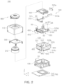
- FIG. 2 is a schematic exploded perspective view of the camera module, according to an embodiment.
- FIG. 3 is a combined perspective view in which only a cover of an aperture module shown in FIG. 2 is disassembled, according to an embodiment.
- FIG. 4 is an exploded perspective view of the aperture module, according to an embodiment
- FIG. 5 is a cross-sectional view taken along line I-I′ of FIG. 3 .
- FIG. 6 illustrates a blade included in the aperture module, according to an embodiment.
- FIG. 7 illustrates another blade included in the aperture module, according to an exemplary embodiment
- FIG. 8 is a plan view of the aperture module when an incident hole has a minimum size, in an embodiment.
- FIG. 9 is a plan view of the aperture module when the incident hole has a medium size, in an embodiment.
- FIG. 10 is a plan view of the aperture module when the incident hole has a maximum size, in an embodiment.
- portion of an element may include the whole element or less than the whole element.
- the term “and/or” includes any one and any combination of any two or more of the associated listed items; likewise, “at least one of” includes any one and any combination of any two or more of the associated listed items.
- first,” “second,” and “third” may be used herein to describe various members, components, regions, layers, or sections, these members, components, regions, layers, or sections are not to be limited by these terms. Rather, these terms are only used to distinguish one member, component, region, layer, or section from another member, component, region, layer, or section. Thus, a first member, component, region, layer, or section referred to in examples described herein may also be referred to as a second member, component, region, layer, or section without departing from the teachings of the examples.
- spatially relative terms such as “above,” “upper,” “below,” “lower,” and the like, may be used herein for ease of description to describe one element's relationship to another element as illustrated in the figures. Such spatially relative terms are intended to encompass different orientations of the device in use or operation in addition to the orientation depicted in the figures. For example, if the device in the figures is turned over, an element described as being “above,” or “upper” relative to another element would then be “below,” or “lower” relative to the other element. Thus, the term “above” encompasses both the above and below orientations depending on the spatial orientation of the device.
- the device may be also be oriented in other ways (rotated 90 degrees or at other orientations), and the spatially relative terms used herein are to be interpreted accordingly.
- FIG. 1 is a perspective view of a camera module 100 , according to an embodiment.
- FIG. 2 is a schematic exploded perspective view of the camera module 100 .
- the camera module 100 may include, for example, a lens barrel 210 , an actuator configured to move the lens barrel 210 , a case 110 and a housing 120 accommodating the lens barrel 210 and the actuator therein, an image sensor module 700 configured to convert light incident through the lens barrel 210 into an electrical signal, and an aperture module 800 configured to adjust an amount of light incident to the lens barrel 210 .
- the lens barrel 210 may have a hollow cylindrical shape so that a plurality of lenses configured to capture an image of a subject may be accommodated therein, and the plurality of lenses may be mounted in the lens barrel 210 along an optical axis.
- the number of lenses disposed in the lens barrel 210 may depend on a design of the lens barrel 210 , and the respective lenses may have optical characteristics such as the same refractive index, different refractive indices, and the like.
- the actuator may move the lens barrel 210 .
- the actuator may move the lens barrel 210 in an optical axis (Z-axis) direction to focus the lenses, and move the lens barrel 210 in a direction perpendicular to the optical axis (the Z-axis) to correct shake at the time of capturing an image.
- the actuator may include a focusing portion 400 configured to focus the lenses and a shake correction portion 500 configured to correct the shake.
- the image sensor module 700 may convert light incident thereto through the lens barrel 210 into an electrical signal.
- the image sensor module 700 may include an image sensor 710 and a printed circuit board 720 connected to the image sensor 710 , and may further include an infrared filter.
- the infrared filter may cut off light in an infrared region in the light incident thereto through the lens barrel 210 .
- the image sensor 710 may convert the light incident thereto through the lens barrel 210 into an electrical signal.
- the image sensor 710 may include a charge coupled device (CCD) or a complementary metal oxide semiconductor (CMOS).
- the electrical signal converted by the image sensor 710 may be output as an image through a display unit of a portable electronic device, for example.
- the image sensor 710 may be fixed to the printed circuit board 720 , and may be electrically connected to the printed circuit board 720 by wire bonding.
- the lens barrel 210 and the actuator may be accommodated in the housing 120 .
- the housing 120 may have a shape of which the top and the bottom of the housing 120 are open, and the lens barrel 210 and the actuator may be accommodated in an internal space of the housing 120 .
- the image sensor module 700 may be disposed on the bottom of the housing 120 .
- the case 110 may be coupled to the housing 120 to surround outer surfaces of the housing 120 , and may protect internal components of the camera module 100 .
- the case 110 may shield electromagnetic waves.
- the case 110 may be formed of a metal and, thus, may be grounded to a ground pad disposed on the printed circuit board 720 , resulting in shielding the electromagnetic waves.
- the actuator may move the lens barrel 210 in order to focus the lenses on the subject.
- the actuator may include the focusing portion 400 configured to move the lens barrel 210 in the optical axis (Z-axis) direction.
- the focusing portion 400 may include a magnet 410 and an integrated coil 420 configured to generate driving force to move the lens barrel 210 and a carrier 300 accommodating the lens barrel 210 therein in the optical axis (Z-axis) direction.
- the magnet 410 may be mounted on the carrier 300 .
- the magnet 410 may be mounted on a first surface of the carrier 300 .
- the coil 420 may be mounted on the housing 120 , and may be disposed to face the magnet 410 .
- the coil 420 may be disposed on a first surface of a substrate 600 , and the substrate 600 may be mounted on the housing 120 .
- the magnet 410 may be mounted on the carrier 300 to thus move in the optical axis (Z-axis) direction together with the carrier 300 , and the coil 420 may be fixed to the housing 120 .
- positions of the magnet 410 and the coil 420 may be exchanged with each other.
- the carrier 300 When a driving signal is applied to the coil 420 , the carrier 300 may be moved in the optical axis (Z-axis) direction by electromagnetic interaction between the magnet 410 and the coil 420 .
- the lens barrel 210 may also be moved in the optical axis (Z-axis) direction by the movement of the carrier 300 .
- the frame 310 , the lens holder 320 , and the lens barrel 210 may be moved together in the optical axis (Z-axis) direction by the movement of the carrier 300 .
- Rolling members B 1 may be disposed between the carrier 300 and the housing 120 to reduce friction between the carrier 300 and the housing 120 when the carrier 300 is moved.
- the rolling members B 1 may have a ball form.
- the rolling members B 1 may be disposed on opposite sides of the magnet 410 .
- a yoke 440 may be disposed on the housing 120 .
- the yoke 440 may be mounted on the substrate 600 and disposed on the housing 120 .
- the yoke 440 may be provided on the second surface of the substrate 600 . Therefore, the yoke 440 may be disposed to face the magnet 410 with the coil 420 interposed therebetween. Attractive force may act in a direction perpendicular to the optical axis (Z-axis) between the yoke 440 and the magnet 410 . Therefore, the rolling members B 1 may be maintained in a state of contact with the carrier 300 and the housing 120 by attractive force between the yoke 440 and the magnet 410 .
- the yoke 440 may collect magnetic force of the magnet 410 to prevent generation of a leaked magnetic flux.
- the yoke 440 and the magnet 410 may form a magnetic circuit.
- the focusing portion may include a position detection element for closed loop control.
- the position detection element may include an AF hall element 430 .
- a magnetic flux value detected by the AF hall element 430 may change according to the movement of the magnet 410 facing the AF hall element 430 .
- the position detection element may detect the position of the lens barrel 210 from a change in the magnetic flux value of the AF hall element 430 according to the movement of the magnet 410 in the optical axis (Z axis) direction.
- the shake correction portion 500 may be operated to correct image blurring or moving picture shaking due to a factor such as handshake of a user at the time of capturing an image or a moving picture. For example, when the shake is generated at the time of capturing the image due to the handshake of the user or the like, the shake correction portion 500 may apply a relative displacement corresponding to the shake to the lens barrel 210 to compensate for the shake. As an example, the shake correction portion 500 may move the lens barrel 210 in the direction perpendicular to the optical axis (the Z-axis) to correct the shake.
- the shake correction portion 500 may include first and second magnets 510 a and 520 a , and first and second coils 510 b and 520 b configured to generate driving force to move a guide member in the direction perpendicular to the optical axis (the Z-axis).
- the frame 310 and the lens holder 320 may be inserted into the carrier 300 , may be stacked in the optical axis (the Z axis) direction, and may guide the movement of the lens barrel 210 .
- the frame 310 and the lens holder 320 may have a space into which the lens barrel 210 may be inserted.
- the lens barrel 210 may be inserted and fixed into the lens holder 320 .
- the frame 310 and the lens holder 320 may be moved in the direction perpendicular to the optical axis (the Z-axis) with respect to the carrier 300 by the driving force generated according to the electromagnetic interaction between the first and second magnets 510 a and 520 a , and the first and second coils 510 b and 520 b , respectively.
- the first magnet 510 a is disposed on a second surface of the lens holder 320 and the first coil 510 b is disposed on the second surface of the substrate 600 , so that the first magnet 510 a and the first coil 510 b may generate driving force in a first axis (Y axis) direction perpendicular to the optical axis (the Z axis).
- a second magnet 520 a is disposed on a third surface of the lens holder 320 and a second coil 520 b is disposed on a third surface of the substrate 600 , so that the second magnet 520 a and the second coil 520 b may generate driving force in a second axis (X axis) direction perpendicular to the first axis (the Y axis).
- the second axis (the X axis) refers to an axis perpendicular to both of the optical axis (the Z axis) and the first axis (the Y axis).
- the first and second magnets 510 a and 520 a may be disposed to be orthogonal to each other on a plane perpendicular to the optical axis (the Z axis).
- the first and second magnets 510 a and 520 a may be mounted on the lens holder 320 , and the first and second coils 510 b and 520 b , which face the first and second magnets 510 a and 520 a , respectively, may be disposed on the substrate 600 and be mounted on the housing 120 .
- the first and second magnets 510 a and 520 a may be moved in the direction perpendicular to the optical axis (the Z axis) together with the lens holder 320 , and the first and second coils 510 b and 520 b may be fixed to the housing 120 .
- positions of the first and second magnets 510 a and 520 a , and the first and second coils 510 b and 520 b may be exchanged with each other.
- the shake correction portion 500 may include a position detection element for closed loop control.
- the position detection element may include first and second optical image stabilization (OIS) hall elements 510 c and 520 c .
- the first and second OIS hall elements 510 c and 520 c may be disposed on the substrate 600 and be mounted on the housing 120 . Therefore, the first and second OIS hall elements 510 c and 520 c may face the first and second magnets 510 a and 520 a , respectively, in the direction perpendicular to the optical axis (Z axis).
- the first OIS hall element 510 c may be disposed on the second surface of the substrate 600
- the second OIS hall element 520 c may be disposed on the third surface of the substrate 600 .
- Magnetic flux values of the first and second OIS hall elements 510 c and 520 c may change according to the movement of the first and second magnets 510 a and 520 a , respectively.
- the position detection element may detect the position of the lens barrel 210 from a change in the magnetic flux values of the first and second OIS hall elements 510 c and 520 c according to the movement of the first and second magnets 510 a and 520 a , respectively, in two directions (X axis direction and Y axis direction) perpendicular to the optical axis.
- the camera module 100 may include a plurality of ball members supporting the shake correction portion 500 .
- the plurality of ball members may serve to guide movements of the frame 310 , the lens holder 320 , and the lens barrel 210 in the shake correction process.
- the plurality of ball members may also serve to maintain an interval between the carrier 300 , the frame 310 , and the lens holder 320 .
- the plurality of ball members may include first ball members B 2 and second ball members B 3 .
- the first ball members B 2 may guide movement of the frame 310 , the lens holder 320 , and the lens barrel 210 in the first axis (Y axis) direction
- the second ball members B 3 may guide movement of the lens holder 320 and the lens barrel 210 in the second axis (X axis) direction.
- the first ball members B 2 may be moved in a rolling motion in the first axis (Y axis) direction when driving force in the first axis (Y axis) direction is generated. Therefore, the first ball members B 2 may guide the movements of the frame 310 , the lens holder 320 , and the lens barrel 210 in the first axis (X axis) direction.
- the second ball members B 3 may be moved in a rolling motion in the second axis (X axis) direction when driving force in the second axis (X axis) direction is generated. Therefore, the second ball members B 3 may guide the movements of the lens holder 320 and the lens barrel 210 in the second axis (X axis) direction.
- the first ball members B 2 may include a plurality of ball members disposed between the carrier 300 and the frame 310
- the second ball members B 3 may include a plurality of ball members disposed between the frame 310 and the lens holder 320 .
- First guide groove portions 301 accommodating the first ball members B 2 therein may be formed, respectively, in surfaces of the carrier 300 and the frame 310 facing each other in the optical axis (Z axis) direction.
- the first guide groove portions 301 may include a plurality of guide grooves corresponding to the plurality of ball members of the first ball members B 2 .
- the first ball members B 2 may be accommodated in the first guide groove portions 301 and be fitted between the carrier 300 and the frame 310 .
- a movement of the first ball members B 2 in the optical axis (Z axis) direction and the second axis (X axis) direction may be restricted, and the first ball members B 2 may be moved in only the first axis (Y axis) direction.
- the first ball members B 2 may be moved in a rolling motion in only the first axis (Y axis) direction.
- a planar shape of each of the plurality of guide grooves of the first guide groove portions 301 may be a rectangular shape having a length in the first axis (Y axis) direction.
- Second guide groove portions 311 accommodating the second ball members B 3 therein may be formed, respectively, in surfaces of the frame 310 and the lens holder 320 facing each other in the optical axis (Z axis) direction.
- the second guide groove portions 311 may include a plurality of guide grooves corresponding to the plurality of ball members of the second ball members B 3 .
- the second ball members B 3 may be accommodated in the second guide groove portions 311 and fitted between the frame 310 and the lens holder 320 .
- a movement of the second ball members B 3 in the optical axis (Z axis) direction and the first axis (Y axis) direction may be restricted, and the second ball members B 3 may only be moved in the second axis (X axis) direction.
- the second ball members B 3 may be moved in a rolling motion in only the second axis (X axis) direction.
- a planar shape of each of the plurality of guide grooves of the second guide groove portions 311 may be a rectangular shape having a length in the second axis (X axis) direction.
- Third ball members B 4 supporting the movement of the lens holder 320 may be provided between the carrier 300 and the lens holder 320 .
- the third ball members B 4 may guide both of movement of the lens holder 320 in the first axis (Y axis) direction and movement of the lens holder 320 in the second axis (X axis) direction.
- the third ball members B 4 may be moved in a rolling motion in the first axis (Y axis) direction when driving force in the first axis (Y axis) direction is generated. Therefore, the third ball members B 4 may guide the movement of the lens holder 320 in the first axis (Y axis) direction.
- the third ball members B 4 may be moved in a rolling motion in the second axis (X axis) direction when driving force in the second axis (X axis) direction is generated. Therefore, the third ball members B 4 may guide the movement of the lens holder 320 in the second axis (X axis) direction. Meanwhile, the second ball members B 3 and the third ball members B 4 may be in contact with and support the lens holder 320 .
- Third guide groove portions 302 accommodating the third ball members B 4 therein may be formed, respectively, in surfaces of the carrier 300 and the lens holder 320 facing each other in the optical axis (Z axis) direction.
- the third ball members B 4 may be accommodated in the third guide groove portions 302 and be fitted between the carrier 300 and the lens holder 320 .
- a movement of the third ball members B 4 in the optical axis (Z axis) direction may be restricted, and the third ball members B 4 may be moved in a rolling motion in the first axis (Y axis) direction and the second axis (X axis) direction.
- a planar shape of each of the third guide groove portions 302 may be a circular shape. Therefore, the third guide groove portions 302 may have a planar shape different from those of the first and second guide groove portions 301 and 311 .
- the first ball members B 2 may be movable in the rolling motion in the first axis (Y axis) direction
- the second ball members B 3 may be movable in the rolling motion in the second axis (X axis) direction
- the third ball members B 4 may be movable in the rolling motion in the first axis (Y axis) direction and the second axis (X axis) direction.
- the frame 310 , the lens holder 320 , and the lens barrel 210 may be moved together in the first axis (Y axis) direction.
- the first ball members B 2 and the third ball members B 4 may be moved in the rolling motion along the first axis (the Y axis). In this case, the movement of the second ball members B 3 may be restricted.
- the lens holder 320 and the lens barrel 210 may be moved in the second axis (X axis) direction.
- the second ball members B 3 and the third ball members B 4 may be moved in the rolling motion along the second axis (the X axis). In this case, the movement of the first ball members B 2 may be restricted.
- a plurality of yokes 510 d and 520 d may be provided so that the shake correction portion 500 and the first to third ball members B 2 , B 3 , and B 4 are maintained in a state in which they are in contact with each other.
- the plurality of yokes 510 d and 520 d may be fixed to the carrier 300 , and may be disposed to face the first and second magnets 510 a and 520 a , respectively, in the optical axis (Z axis) direction. Therefore, attractive force may be generated in the optical axis (Z axis) direction between the plurality of yokes 510 d and 520 d and the first and second magnets 510 a and 520 a , respectively.
- the frame 310 and the lens holder 320 of the shake correction portion 500 may be maintained in a state in which they are in contact with the first to third ball members B 2 , B 3 , and B 4 .
- the plurality of yokes 510 d and 520 d may be formed of a material that may generate the attractive force between the plurality of yokes 510 d and 520 d and the first and second magnets 510 a and 520 a , respectively.
- the plurality of yokes 510 d and 520 d may be formed of a magnetic material.
- the plurality of yokes 510 d and 520 d may be provided so that the frame 310 and the lens holder 320 may be maintained in the state in which they are in contact with the first to third ball members B 2 , B 3 , and B 4 , and a stopper 330 may be provided to prevent the first to third ball members B 2 , B 3 , and B 4 , the frame 310 , and the lens holder 320 from being externally separated from the carrier 300 due to external impact, or the like.
- the stopper 330 may be coupled to the carrier 300 to cover at least a portion of an upper surface of the lens holder 320 .
- the camera module 100 may include an aperture module 800 .
- the aperture module 800 may be coupled to the lens barrel 210 through an upper portion of the case 110 .
- the aperture module 800 may be mounted on the lens holder 320 , into which the lens barrel 210 is fixedly inserted, and may be coupled to the lens barrel 210 . Therefore, the aperture module 800 may move together with the lens barrel 210 and the lens holder 320 .
- the aperture module 800 may include a magnet 890 ( FIG. 3 ).
- the magnet 890 is a part of a driving portion capable of adjusting an incident hole of the aperture module 800 .
- the magnet 890 may include two magnetic materials having different polarities.
- the aperture driving portion may include a coil 540 configured to electromagnetically interact with the magnet 890 .
- the coil 540 may be disposed on a fourth surface of the substrate 600 to face the magnet 890 . Since the coil 540 is disposed on the fourth surface of the substrate 600 , the magnet 890 and the coil 540 may generate a driving force in the first axis (Y axis) direction.
- a hall element 530 may be fixedly disposed to face the magnet 890 on the fourth surface of the substrate 600 .
- the hall element 530 may include a first hall element 531 and a second hall element 532 disposed with the coil 540 interposed therebetween.
- a magnetic flux value of the hall element 530 may change according to movement of the magnet 890 .
- a position of the magnet 890 may be detected from the magnetic flux value of the hall element 530 .
- FIG. 3 is a combined perspective view in which only a cover 820 of the aperture module 800 is disassembled, according to an embodiment.
- FIG. 4 is an exploded perspective view of the aperture module 800 , according to an embodiment.
- FIG. 5 is a cross-sectional view taken along line I-I′ of FIG. 3 .
- the aperture module 800 may include a base 810 , a rotating plate 840 , and blades 860 and 870 .
- the rotating plate 840 may be rotatably disposed on the base 810 .
- the rotating plate 840 may rotate with respect to the base 810 in a plane perpendicular to the optical axis.
- the rotating plate 840 may have a ring shape in which a center of the rotating plate 840 coincides with the optical axis.
- the base 810 may include extension portions 812 , 813 , and 814 guiding the rotation of the rotating plate 840 .
- the base 810 may include extension portions 812 , 813 , and 814 extending in the optical axis direction to be in contact with an outer circumferential surface of the rotating plate 840 .
- the extension portion 812 , 813 , and 814 may guide the rotation of the rotating plate 840 .
- the base 810 may have three extension portions 812 , 813 , and 814 on one surface thereof, and one side surfaces 812 a , 813 a , and 814 a of the extension portions 812 , 813 , and 814 may be in contact with the outer circumferential surface 844 of the rotating plate 840 .
- a clearance may exist between the extension portions 812 , 813 , and 814 and the outer circumferential surface 844 of the rotating plate 840 so that the rotating plate 840 may rotate smoothly.
- the extension portions 812 , 813 , and 814 may limit a movement direction of the rotating plate 840 so that a rotational center of the rotating plate 840 deviates from the optical axis.
- the rotating plate 840 may include an opening 845 .
- Blades 860 and 870 to be described later may be disposed inside the opening 845 of the rotating plate 840 .
- the aperture module 800 may include the aperture driving portion capable of rotating the rotating plate 840 .
- the aperture driving portion may include the moving portion 850 , which is attached to the base 810 , the magnet 890 , and the coil 540 .
- the moving portion 850 may be slidable in one direction with respect to the base 810 .
- the base 810 may include a guide 815 to which the moving portion 850 may be mounted. The moving portion 850 may slide on the guide 815 .
- ball members B 5 may be disposed between the moving portion 850 and the guide 815 in order to reduce a frictional force between the moving portion 850 and the guide 815 .
- the moving portion 850 and/or the guide 815 may include a guide groove partially accommodating the ball members B 5 , and a movement direction of the ball members B 5 may be restricted to a direction in which the guide groove extends.
- the moving portion 850 and/or the guide 815 may include a guide groove extending parallel to a slide direction of the moving portion 850 .
- the moving portion 850 may be driven by an electromagnetic force.
- the magnet 890 may be attached to the moving portion 850 .
- the magnet 890 may receive an electromagnetic force by interaction with the coil 540 . According to the electromagnetic interaction between the magnet 890 and the coil 540 , the moving portion 850 may reciprocatively slide with respect to the base 810 .
- the rotating plate 840 may interact with the moving portion 850 .
- a portion of the moving portion 850 may push the rotating plate 840 in a circumferential direction according to the movement of the moving portion 850 , which may rotate the rotating plate 840 .
- the moving portion 850 may include a protruding portion 851 extending to the rotating plate 840 .
- the rotating plate 840 may include an accommodating portion 848 configured to accommodate the protruding portion 851 .
- the protruding portion 851 may rotate the rotating plate 840 while pushing a point of the rotating plate 840 .
- the moving portion 850 may include a pin extending toward the rotating plate 840 , and the rotating plate 840 may have a recess configured to accommodate the pin.
- the aperture module 800 may include blades 860 and 870 .
- the blades 860 and 870 may define an incident hole of the aperture.
- the blades 860 and 870 may be arranged in a circumferential direction, and surfaces facing the centers of the blades 860 and 870 may define the incident hole of the aperture.
- the aperture module 800 may include blades 860 and 870 having different shapes. In an embodiment, the aperture module 800 may include a first type blade 860 and a second type blade 870 . In an embodiment, the first type blades 860 and the second type blades 870 may be arranged in alternating order in the circumferential direction.
- first type blades 860 and two or more second type blades 870 may be provided. According to the embodiment illustrated in FIG. 3 , three first type blades 860 and three second type blades 870 may be arranged in alternating order in the circumferential direction.
- the first type blades 860 and the second type blades 870 may be arranged at equal intervals in the circumferential direction with respect to the optical axis. In the illustrated embodiment, six total blades 860 and 870 may be arranged at equal intervals in the circumferential direction with respect to the optical axis, and the incident hole may have a hexagonal shape. In an embodiment, the first type blades 860 and the second type blades 870 may be arranged so that the distances between the blades 860 and 870 and the optical axis are all the same or substantially the same. In another embodiment, when the aperture module 800 includes two first type blades 860 and two second type blades 870 , the shape of the incident hole may be a tetragonal shape. In another embodiment, when the aperture module 800 includes four first type blades 860 and four second type blades 870 , the shape of the incident hole may be an octagonal shape.
- first type blades 860 and the second type blades 870 may be disposed to at least partially overlap each other in the optical axis direction.
- the first type blades 860 may at least partially overlap adjacent second type blades 870 .
- the first type blades 860 and the second type blades 870 may be disposed in the opening 845 of the rotating plate 840 . Since the first type blades 860 and the second type blades 870 are provided in the opening 845 of the rotating plate 840 , the first type blades 860 and the second type blades 870 may not overlap the rotating plate 840 . In an embodiment, when the aperture module 800 is viewed in the optical axis direction, the first type and second type blades 860 and 870 and the rotating plate 840 may be disposed in regions separated from each other.
- the first type and second type blades 860 and 870 may only be positioned inside the opening 845 of the rotating plate 840 , and may not invade the region outside the opening 845 . Since the first type and second type blades 860 and 870 are disposed so as not to overlap the rotating plate 840 , the aperture module 800 may be implemented to have a thin thickness.
- the first type and second type blades 860 and 870 may be disposed on the same surface as the rotating plate 840 in the optical axis direction.
- an upper surface 841 of the rotating plate 840 and upper surfaces of the first type and second type blades 860 and 870 may coincide or substantially coincide.
- At least one of the first type and second type blades 860 and 870 may interact with the rotating plate 840 through a link 880 .
- at least one of the first type and second type blades 860 and 870 may be connected to the rotating plate 840 through the link 880 .
- One end of the link 880 may be connected to the at least one of the first type and second type blades 860 and 870 , and the other end of the link 880 may be connected to the rotating plate 840 .
- the link 880 may be rotatably coupled to at least one of the first type and second type blades 860 and 870 and the rotating plate 840 , respectively.
- the link 880 may include a first hole 884 at the one end thereof and a second hole 883 at the other end thereof.
- the rotating plate 840 may include a first pin 846 corresponding to the first hole 884
- at least one of the first type and second type blades 860 and 870 may include second pin 865 and 875 , respectively, corresponding to the second hole 883 .
- the first hole 884 and the second hole 883 may be attached to the first pin 846 and the second pins 865 and 875 , respectively.
- the first pin 846 may be disposed in a depression portion 847 having a height lower than the upper surface 841 of the rotating plate 840 .
- a size of the incident hole may be adjusted by interaction of the first type and second type blades 860 and 870 .
- the first type and second type blades 860 and 870 which are arranged in the circumferential direction, interact together to become closer to or farther away from the optical axis, and accordingly, the size of the incident hole may be reduced or increased.
- the first type and second type blades 860 and 870 may interact with the rotating plate 840 . As the first type and second type blades 860 and 870 move according to the rotation of the rotating plate 840 , the size of the incident hole may be adjusted.
- the first type and second type blades 860 and 870 may move in a direction away from or toward the optical axis. In an embodiment, the first type and second type blades 860 and 870 may move radially about the optical axis. When the blades 860 and 870 interact with the rotating plate 840 , the first type and second type blades 860 and 870 may simultaneously approach the optical axis or move away from the optical axis. Accordingly, the size of the incident hole defined by the first type and second type blades 860 and 870 may be adjusted.
- the aperture module 800 may include a structure guiding the first type and second type blades 860 and 870 to move in a certain path according to the rotation of the rotating plate 840 .
- the aperture module 800 may further include a guide plate 830 disposed under the first type and second type blades 860 and 870 . Referring to FIG. 5 , the guide plate 830 may be disposed on the base 810 , and the blades 860 and 870 may be disposed on the guide plate 830 .
- the guide plate 830 may be fixedly attached to the base 810 .
- the base 810 may include a seating surface 811 for the guide plate 830 , and a lower surface 832 of the guide plate 830 may be disposed on the seating surface 811 of the base 810 .
- the base 810 may include an opening 816 for light passing through the incident hole by the first type and second type blades 860 and 870 .
- the guide plate 830 may have a ring shape.
- the first type and second type blades 860 and 870 and the rotating plate 840 may be disposed on regions of the guide plate 830 separated from each other and may not overlap each other.
- an inner diameter of the guide plate 830 may be smaller than the inner diameter of the rotating plate 840 .
- the upper surface of the guide plate 830 may be divided into two regions based on the inner diameter of the rotating plate 840 .
- the rotating plate 840 may be seated on a portion of the guide plate 830 that is larger than the inner diameter of the rotating plate 840 .
- the first type and second type blades 860 and 870 may be seated on a portion of the guide plate 830 that is smaller than the inner diameter of the rotating plate 840 .
- the guide plate 830 may include a protruding portion 834 extending toward the first type and second type blades 860 and 870 .
- the first type and second type blades 860 and 870 may be seated on the upper surface of the guide plate 830 , and the protruding portion 834 corresponding to the at least one of the first type and second type blades 860 and 870 may be disposed on the upper surface of the guide plate 830 .
- At least one of the first type and second type blades 860 and 870 may include guide grooves 869 and 879 , respectively, configured to accommodate at least a portion of the protruding portion 834 . Since the protruding portion 834 has a fixed position with respect to the base 810 , the movement direction of the first type and second type blades 860 and 870 with respect to the base 810 may be restricted to a direction in which the guide grooves 869 and 879 extend.
- first type and second type blades 860 and 870 may move linearly with respect to the guide plate 830 .
- shape of the guide grooves 869 and 879 and the protruding portion 834 may be formed so that the blades 860 and 870 may move linearly with respect to the guide plate 830 .
- the guide grooves 869 and 879 may linearly extend, and the protruding portion 834 may extend in a direction parallel to the direction in which the guide grooves 869 and 879 extend.
- the protruding portion 834 may have a shape of a square column extending in a direction parallel to the direction in which the guide grooves 869 and 879 extend, or may have a shape of an elliptical cylinder having a long axis parallel to the direction in which the guide grooves 869 and 879 extend.
- the guide grooves 869 and 879 may linearly extend, and the protruding portion 834 may include two or more protrusions aligned in the direction in which the guide grooves 869 and 879 extend.
- the guide grooves 869 and 879 may extend radially from the optical axis. In an embodiment, the guide grooves 869 and 879 may extend parallel to a radial direction from the center of rotation of the rotating plate 840 . Accordingly, the first type and second type blades 860 and 870 may move in a direction toward the optical axis or away from the optical axis.
- the first type blade 860 may include the first guide groove 869 accommodating the protruding portion 834 .
- the first type blade 860 may move parallel to a direction in which the first guide groove 869 extends due to an interaction between the first guide groove 869 and the protruding portion 834 .
- the first guide groove 869 may extend in a direction toward the optical axis.
- the first guide groove 869 may extend in a radial direction from the optical axis. For example, an imaginary extension line of the first guide groove 869 may cross the optical axis.
- the second type blade 870 may include a second guide groove 879 accommodating the protruding portion 834 .
- the second type blade 870 may move parallel to a direction in which the second guide groove 879 extends due to an interaction between the second guide groove 879 and the protruding portion 834 .
- the second guide groove 879 may extend in a direction toward the optical axis.
- the second guide groove 879 may extend in a radial direction from the optical axis. For example, an imaginary extension line of the second guide groove 879 may cross the optical axis.
- the guide grooves may be disposed in the guide plate 830 and the protruding portion may be disposed on the first type and second type blades 860 and 870 .
- the first type and second type blades 860 and 870 may move along a direction in which the guide groove provided in the guide plate 830 extends.
- the guide grooves 869 and 879 provided in the guide plate 830 may extend radially around the optical axis.
- the first type and second type blades 860 and 870 may be disposed to at least partially overlap each other.
- the first type and second type blades 860 and 870 may at least partially overlap each other in the optical axis direction.
- the first type and second type blades 860 and 870 may be disposed to overlap each other. Since the first type and second type blades 860 and 870 are disposed so as to overlap each other, the aperture module 800 may be implemented to have a thin thickness.
- the aperture module 800 may include an aperture cover 820 .
- the aperture cover 820 may form a portion of the exterior of the aperture module 800 .
- the aperture cover 820 may protect internal components of the aperture module 800 .
- a portion of the aperture cover 820 may be disposed on the rotating plate 840 and the first type and second type blades 860 and 870 .
- the aperture cover 820 may restrict the rotating plate 840 and the blades 860 and 870 to move on a designated plane.
- the aperture cover 820 may function to press the rotating plate 840 and/or the first type and second type blades 860 and 870 in the optical axis direction so that the rotating plate 840 and/or the first type and second type blades 860 and 870 may be moved in a state adjacent to the upper surface 831 of the guide plate 830 .
- a predetermined clearance may exist between the rotating plate 840 and/or the first type and second type blades 860 and 870 and the aperture cover 820 .
- FIG. 6 illustrates the first type blade 860 , according to an embodiment.
- FIG. 7 illustrates the second type blade 870 , according to an embodiment.
- the first type blade 860 may include the pin 865 that may be coupled to the link 880 .
- the first type blade 860 may include a depression portion 866 having a height lower than that of an upper surface 861 of the first type blade 860 , and the first pin 846 may extend from the depression portion 866 .
- a lower surface 882 of the link 880 may be seated on the depression portion 866 . Therefore, even if the link 880 is attached to overlap the first type blade 860 , the overall thickness of the aperture module 800 may be reduced. For example, when the link 880 is attached to the first type blade 860 , an upper surface 881 of the link 880 and the upper surface 861 of the first type blade 860 may coincide or substantially coincide.
- the first type blade 860 may include the first guide groove 869 configured to accommodate at least a portion of the protruding portion 834 of the guide plate 830 on the lower surface 862 .
- the first type blade 860 may include a portion 867 having a thin thickness.
- the thin portion 867 may be defined by surfaces 868 a and 868 b having a height lower than that of the upper surface 861 and the lower surface 862 .
- the first type blade 860 may be have a thick portion (or a first portion) at a central region thereof and a thin portion 867 (or a second portion) at an end region thereof, based on a stepped portion S.
- the second type blade 870 may include the pin 875 that may be coupled to the link 880 .
- the second type blade 870 may include a depression portion 876 having a height lower than that of an upper surface 871 of the second type blade 870 , and the pin 875 may extend from the depression portion 876 .
- the lower surface 882 of the link 880 may be seated on the depression portion 876 . Therefore, even if the link 880 is attached to overlap the second type blade 870 , the overall thickness of the aperture module 800 may be reduced. For example, when the link 880 is attached to the second type blade 870 , the upper surface 881 of the link 880 and the upper surface 871 of the second type blade 870 may coincide or substantially coincide.
- the second type blade 870 may include the second guide groove 879 configured to accommodate at least a portion of the protruding portion 834 of the guide plate 830 on the lower surface 872 .
- the second type blade 870 may include an accommodating groove 877 at an end region thereof, into which a portion of the first type blade 860 may be inserted.
- the thin portion 867 of the first type blade 860 may be accommodated in the accommodating groove 877 of the second type blade 870 .
- the thin portion 867 of the first type blade 860 may be positioned between two surfaces 878 a and 878 b each defining the accommodating groove 877 .
- a portion of the first type blade 860 may be selectively accommodated in the second type blade 870 according to the driving of the aperture.
- an overlapping region between the first type blade 860 and the second type blade 870 may increase.
- the overlapping region between the first type blade 860 and the second type blade 870 may decrease. That is, according to the size of the incident hole, a portion of the thin portion 867 of the first type blade 860 may be selectively accommodated in the accommodating groove 877 of the second type blade 870 .
- a shape of the stepped portion S of the first type blade 860 may correspond to a shape of an edge of the second type blade 870 .
- the edge of the second type blade 870 may come into contact with (e.g., interface with) the stepped portion of the adjacent first type blade 860 .
- inner side surfaces 863 and 873 of the blades 860 and 870 facing the optical axis may have a plane.
- outer side surfaces 864 and 874 of the first type and second type blades 860 and 870 , respectively, facing the rotating plate 840 may have a curved surface. Referring to FIG. 10 , when the size of the incident hole is the maximum size, the outer side surfaces 864 and 874 of the first type and second type blades 860 and 870 , respectively, may be adjacent to an inner circumferential surface 843 of the rotating plate 840 .
- FIG. 8 is a plan view of the aperture module 800 when an incident hole has the minimum size, in an embodiment.
- FIG. 9 is a plan view of the aperture module 800 when an incident hole has a medium size, in an embodiment.
- FIG. 10 is a plan view of the aperture module 800 when an incident hole has the maximum size, in an embodiment.
- the aperture module 800 may provide the incident hole to have various sizes.
- the incident hole may be defined by side surfaces of the first type and second type blades 860 and 870 in the optical axis direction, and, in an embodiment, the size of the incident hole may continuously change according to the movement of the moving portion 850 .
- the protruding portion 834 may rotate the rotating plate 840 in a counterclockwise direction.
- the rotating plate 840 rotates, the first type and second type blades 860 and 870 may move away from the optical axis, and the size of the incident hole may be expanded.
- the rotating plate 840 may rotate in a clockwise direction, and the first type and second type blades 860 and 870 may move toward the optical axis. Accordingly, the size of the incident hole may be reduced.
- the protruding portion 851 of the moving portion 850 may be positioned between the first point P 1 and the second point P 2 .
- the moving portion 850 may be positioned at an arbitrary point Pa between the first point P 1 and the second point P 2 by the electromagnetic force acting on the magnet 890 .
- the aperture module 800 may provide an incident hole 801 having a minimum size.
- the aperture module 800 may provide an incident hole 803 having a maximum size.
- the position of the moving portion 850 and the size of the incident hole may correspond one-to-one.
- the size of the incident hole may be continuously increased.
- the size of the incident hole may be continuously decreased.
- the aperture module 800 may provide an incident hole 802 having a medium size.
- the first type and second type blades 860 and 870 move uniformly, and therefore, the shape of the incident hole may be maintained to be constant.
- the shape of the incident hole may remain a regular hexagon.
- an amount of incident light may be selectively changed through the aperture module, deterioration of performance of the auto-focusing function may be prevented even though the aperture module is mounted in the camera module, and an increase in the weight of the camera module due to inclusion of the aperture module may be significantly reduced.
- the aperture module may be capable of continuously implementing an accurate aperture diameter while reducing the use of current.
- the thickness of the aperture module may be prevented from increasing while forming the incident hole using a number of blades.
Landscapes
- Physics & Mathematics (AREA)
- General Physics & Mathematics (AREA)
- Optics & Photonics (AREA)
- Engineering & Computer Science (AREA)
- Multimedia (AREA)
- Signal Processing (AREA)
- Adjustment Of Camera Lenses (AREA)
- Studio Devices (AREA)
Abstract
Description
Claims (24)
Applications Claiming Priority (2)
| Application Number | Priority Date | Filing Date | Title |
|---|---|---|---|
| KR10-2020-0139601 | 2020-10-26 | ||
| KR1020200139601A KR102439907B1 (en) | 2020-10-26 | 2020-10-26 | Aperture module and camera module including the same |
Publications (2)
| Publication Number | Publication Date |
|---|---|
| US20220128832A1 US20220128832A1 (en) | 2022-04-28 |
| US12013550B2 true US12013550B2 (en) | 2024-06-18 |
Family
ID=80515883
Family Applications (1)
| Application Number | Title | Priority Date | Filing Date |
|---|---|---|---|
| US17/179,655 Active 2041-11-24 US12013550B2 (en) | 2020-10-26 | 2021-02-19 | Aperture module and camera module |
Country Status (3)
| Country | Link |
|---|---|
| US (1) | US12013550B2 (en) |
| KR (1) | KR102439907B1 (en) |
| CN (2) | CN114509904B (en) |
Families Citing this family (6)
| Publication number | Priority date | Publication date | Assignee | Title |
|---|---|---|---|---|
| KR102439907B1 (en) * | 2020-10-26 | 2022-09-05 | 삼성전기주식회사 | Aperture module and camera module including the same |
| TWI814457B (en) * | 2022-05-26 | 2023-09-01 | 大立光電股份有限公司 | Light pass aperture module, camera module and electronic device |
| KR20240158599A (en) * | 2023-04-27 | 2024-11-05 | 자화전자(주) | IRIS device and camera module including the same |
| CN119471942B (en) * | 2023-07-28 | 2025-10-14 | 宁波舜宇光电信息有限公司 | Lens assemblies, camera modules and electronic equipment |
| WO2025028935A1 (en) * | 2023-07-28 | 2025-02-06 | 엘지이노텍(주) | Aperture module, and lens module and camera device including same |
| WO2025263959A1 (en) * | 2024-06-17 | 2025-12-26 | 삼성전자 주식회사 | Electronic device including camera module |
Citations (17)
| Publication number | Priority date | Publication date | Assignee | Title |
|---|---|---|---|---|
| US1861257A (en) * | 1929-10-25 | 1932-05-31 | Barenyi Arpad | Photographic shutter |
| US3980407A (en) * | 1975-01-17 | 1976-09-14 | Electromask, Inc. | Shutter plate movement |
| WO2003028074A1 (en) * | 2001-09-26 | 2003-04-03 | Nikon Corporation | Diaphragm device, projection optical system and projection exposure device, and micro-device producing method |
| JP2005079555A (en) | 2003-09-03 | 2005-03-24 | Nikon Corp | Aperture device and exposure device |
| JP2005338711A (en) | 2004-05-31 | 2005-12-08 | Nisca Corp | Light quantity adjusting device and projector apparatus using same |
| KR20090050608A (en) | 2007-11-16 | 2009-05-20 | 성우전자 주식회사 | Lens protection device for mobile phone camera |
| US20160178989A1 (en) * | 2014-12-17 | 2016-06-23 | Canon Kabushiki Kaisha | Lens barrel and optical apparatus |
| US20190373145A1 (en) | 2018-06-05 | 2019-12-05 | Samsung Electronics Co., Ltd. | Camera module for controlling iris diaphragm using signal corrected according to position of lens assembly, electronic device including the camera module, and method for operating the electronic device |
| CN209979707U (en) | 2019-04-02 | 2020-01-21 | 德淮半导体有限公司 | Probe card |
| US20200028998A1 (en) | 2018-07-20 | 2020-01-23 | Samsung Electro-Mechanics Co., Ltd. | Aperture module and camera module including the same |
| US20200026149A1 (en) | 2018-07-20 | 2020-01-23 | Samsung Electro-Mechanics Co., Ltd. | Aperture stop module |
| US20200241387A1 (en) | 2019-01-29 | 2020-07-30 | Samsung Electro-Mechanics Co., Ltd. | Aperture module and camera module including the same |
| CN111596500A (en) | 2020-06-22 | 2020-08-28 | 睿恩光电有限责任公司 | Aperture device, camera device, and electronic apparatus |
| US20200278590A1 (en) * | 2019-02-28 | 2020-09-03 | Panasonic Intellectual Property Management Co., Ltd. | Light shielding unit and lens barrell provided with same |
| US20200301246A1 (en) | 2019-03-21 | 2020-09-24 | Samsung Electro-Mechanics Co., Ltd. | Aperture module, camera module, and portable electronic device |
| CN212255876U (en) | 2019-06-28 | 2020-12-29 | 三星电机株式会社 | Aperture module and camera module including the same |
| US20210109305A1 (en) * | 2019-10-09 | 2021-04-15 | Tdk Taiwan Corp. | Optical element driving mechanism |
Family Cites Families (2)
| Publication number | Priority date | Publication date | Assignee | Title |
|---|---|---|---|---|
| US10812692B2 (en) | 2018-08-22 | 2020-10-20 | Samsung Electro-Mechanics Co., Ltd. | Aperture module and camera module including the same |
| KR102439907B1 (en) * | 2020-10-26 | 2022-09-05 | 삼성전기주식회사 | Aperture module and camera module including the same |
-
2020
- 2020-10-26 KR KR1020200139601A patent/KR102439907B1/en active Active
-
2021
- 2021-02-19 US US17/179,655 patent/US12013550B2/en active Active
- 2021-07-07 CN CN202110766920.4A patent/CN114509904B/en active Active
- 2021-07-07 CN CN202121541862.7U patent/CN215986834U/en active Active
Patent Citations (23)
| Publication number | Priority date | Publication date | Assignee | Title |
|---|---|---|---|---|
| US1861257A (en) * | 1929-10-25 | 1932-05-31 | Barenyi Arpad | Photographic shutter |
| US3980407A (en) * | 1975-01-17 | 1976-09-14 | Electromask, Inc. | Shutter plate movement |
| WO2003028074A1 (en) * | 2001-09-26 | 2003-04-03 | Nikon Corporation | Diaphragm device, projection optical system and projection exposure device, and micro-device producing method |
| JP2005079555A (en) | 2003-09-03 | 2005-03-24 | Nikon Corp | Aperture device and exposure device |
| JP2005338711A (en) | 2004-05-31 | 2005-12-08 | Nisca Corp | Light quantity adjusting device and projector apparatus using same |
| KR20090050608A (en) | 2007-11-16 | 2009-05-20 | 성우전자 주식회사 | Lens protection device for mobile phone camera |
| US20160178989A1 (en) * | 2014-12-17 | 2016-06-23 | Canon Kabushiki Kaisha | Lens barrel and optical apparatus |
| US20190373145A1 (en) | 2018-06-05 | 2019-12-05 | Samsung Electronics Co., Ltd. | Camera module for controlling iris diaphragm using signal corrected according to position of lens assembly, electronic device including the camera module, and method for operating the electronic device |
| KR20190138344A (en) | 2018-06-05 | 2019-12-13 | 삼성전자주식회사 | Camera Module including a aperture and Electronic device including the same |
| US20200028998A1 (en) | 2018-07-20 | 2020-01-23 | Samsung Electro-Mechanics Co., Ltd. | Aperture module and camera module including the same |
| US20200026149A1 (en) | 2018-07-20 | 2020-01-23 | Samsung Electro-Mechanics Co., Ltd. | Aperture stop module |
| CN110737147A (en) | 2018-07-20 | 2020-01-31 | 三星电机株式会社 | Aperture diaphragm module |
| CN110737146A (en) | 2018-07-20 | 2020-01-31 | 三星电机株式会社 | Aperture module and camera module including the same |
| US20200241387A1 (en) | 2019-01-29 | 2020-07-30 | Samsung Electro-Mechanics Co., Ltd. | Aperture module and camera module including the same |
| KR20200093997A (en) | 2019-01-29 | 2020-08-06 | 삼성전기주식회사 | Aperture module and camera module including the same |
| US20200278590A1 (en) * | 2019-02-28 | 2020-09-03 | Panasonic Intellectual Property Management Co., Ltd. | Light shielding unit and lens barrell provided with same |
| KR20200112158A (en) | 2019-03-21 | 2020-10-05 | 삼성전기주식회사 | Aperture module and camera module including the same |
| US20200301246A1 (en) | 2019-03-21 | 2020-09-24 | Samsung Electro-Mechanics Co., Ltd. | Aperture module, camera module, and portable electronic device |
| CN209979707U (en) | 2019-04-02 | 2020-01-21 | 德淮半导体有限公司 | Probe card |
| CN212255876U (en) | 2019-06-28 | 2020-12-29 | 三星电机株式会社 | Aperture module and camera module including the same |
| US20200409234A1 (en) | 2019-06-28 | 2020-12-31 | Samsung Electro-Mechanics Co., Ltd. | Aperture module and camera module including the same |
| US20210109305A1 (en) * | 2019-10-09 | 2021-04-15 | Tdk Taiwan Corp. | Optical element driving mechanism |
| CN111596500A (en) | 2020-06-22 | 2020-08-28 | 睿恩光电有限责任公司 | Aperture device, camera device, and electronic apparatus |
Non-Patent Citations (4)
| Title |
|---|
| Chinese Office Action Issued on Mar. 29, 2024, in Counterpart Chinese Patent Application No. 202110766920.4 (4 Pages in English, 6 Pages in Chinese). |
| Chinese Office Action issued on Oct. 27, 2021 in corresponding Chinese Patent Application No. 202121541862.7 (2 pages in English, 2 pages in Chinese). |
| Korean Office Action issued on Jan. 26, 2022 in corresponding Korean Patent Application No. 10-2020-0139601 (5 pages in English and 4 pages in Korean). |
| Machine translation of WO-03028074-A1 (Year: 2003). * |
Also Published As
| Publication number | Publication date |
|---|---|
| KR20220055298A (en) | 2022-05-03 |
| US20220128832A1 (en) | 2022-04-28 |
| KR102439907B1 (en) | 2022-09-05 |
| CN114509904A (en) | 2022-05-17 |
| CN215986834U (en) | 2022-03-08 |
| CN114509904B (en) | 2025-02-21 |
Similar Documents
| Publication | Publication Date | Title |
|---|---|---|
| US12013550B2 (en) | Aperture module and camera module | |
| US11156898B2 (en) | Aperture module, camera module, and portable electronic device | |
| US11226539B2 (en) | Aperture module and camera module including the same | |
| US11768346B2 (en) | Optical mechanism | |
| US11754851B2 (en) | Lens driving apparatus having three ball members and opening in frame | |
| US10969654B2 (en) | Aperture module and camera module including the same | |
| EP3785059B1 (en) | An optical-path folding-element with an extended two degree of freedom rotation range | |
| US10824051B2 (en) | Aperture module and camera module including the same | |
| US11493741B2 (en) | Reflective module and camera module including the same | |
| CN110830687B (en) | Aperture module and camera module including the same | |
| JP5923558B2 (en) | Optical vibration prevention mechanism that can switch optical paths | |
| US10931857B2 (en) | Aperture module and camera module including the same | |
| US10812697B2 (en) | Camera module | |
| TWI765947B (en) | Image capturing module having multiple lenses | |
| US10701248B2 (en) | Iris module and camera module including the same | |
| US11347134B2 (en) | Camera module | |
| US11762167B2 (en) | Camera module | |
| US20240219811A1 (en) | Aperture module and camera module including the same | |
| US12554179B2 (en) | Aperture module and camera module including the same | |
| US12547052B2 (en) | Camera module | |
| US20240085760A1 (en) | Aperture module and camera module including the same | |
| US20240231190A1 (en) | Camera module | |
| US20240319568A1 (en) | Camera module | |
| US20230266638A1 (en) | Camera module | |
| US20250330709A1 (en) | Camera module |
Legal Events
| Date | Code | Title | Description |
|---|---|---|---|
| AS | Assignment |
Owner name: SAMSUNG ELECTRO-MECHANICS CO., LTD., KOREA, REPUBLIC OF Free format text: ASSIGNMENT OF ASSIGNORS INTEREST;ASSIGNORS:HWANG, SE YEON;KIM, SEOK HWAN;REEL/FRAME:055330/0667 Effective date: 20210202 |
|
| FEPP | Fee payment procedure |
Free format text: ENTITY STATUS SET TO UNDISCOUNTED (ORIGINAL EVENT CODE: BIG.); ENTITY STATUS OF PATENT OWNER: LARGE ENTITY |
|
| STPP | Information on status: patent application and granting procedure in general |
Free format text: DOCKETED NEW CASE - READY FOR EXAMINATION |
|
| STPP | Information on status: patent application and granting procedure in general |
Free format text: RESPONSE TO NON-FINAL OFFICE ACTION ENTERED AND FORWARDED TO EXAMINER |
|
| STPP | Information on status: patent application and granting procedure in general |
Free format text: FINAL REJECTION MAILED |
|
| STPP | Information on status: patent application and granting procedure in general |
Free format text: RESPONSE AFTER FINAL ACTION FORWARDED TO EXAMINER |
|
| STPP | Information on status: patent application and granting procedure in general |
Free format text: ADVISORY ACTION MAILED |
|
| STPP | Information on status: patent application and granting procedure in general |
Free format text: DOCKETED NEW CASE - READY FOR EXAMINATION |
|
| STPP | Information on status: patent application and granting procedure in general |
Free format text: NON FINAL ACTION MAILED |
|
| STPP | Information on status: patent application and granting procedure in general |
Free format text: RESPONSE TO NON-FINAL OFFICE ACTION ENTERED AND FORWARDED TO EXAMINER |
|
| STPP | Information on status: patent application and granting procedure in general |
Free format text: NOTICE OF ALLOWANCE MAILED -- APPLICATION RECEIVED IN OFFICE OF PUBLICATIONS |
|
| STPP | Information on status: patent application and granting procedure in general |
Free format text: NOTICE OF ALLOWANCE MAILED -- APPLICATION RECEIVED IN OFFICE OF PUBLICATIONS |
|
| STPP | Information on status: patent application and granting procedure in general |
Free format text: PUBLICATIONS -- ISSUE FEE PAYMENT RECEIVED |
|
| STPP | Information on status: patent application and granting procedure in general |
Free format text: PUBLICATIONS -- ISSUE FEE PAYMENT VERIFIED |
|
| STCF | Information on status: patent grant |
Free format text: PATENTED CASE |