US11975367B2 - Pipe cleaning and/or pipe inspection nozzle including extension sleeve - Google Patents
Pipe cleaning and/or pipe inspection nozzle including extension sleeve Download PDFInfo
- Publication number
- US11975367B2 US11975367B2 US17/155,993 US202117155993A US11975367B2 US 11975367 B2 US11975367 B2 US 11975367B2 US 202117155993 A US202117155993 A US 202117155993A US 11975367 B2 US11975367 B2 US 11975367B2
- Authority
- US
- United States
- Prior art keywords
- extension sleeve
- nozzle
- sleeve
- section
- metallic
- Prior art date
- Legal status (The legal status is an assumption and is not a legal conclusion. Google has not performed a legal analysis and makes no representation as to the accuracy of the status listed.)
- Active, expires
Links
Images


Classifications
-
- B—PERFORMING OPERATIONS; TRANSPORTING
- B05—SPRAYING OR ATOMISING IN GENERAL; APPLYING FLUENT MATERIALS TO SURFACES, IN GENERAL
- B05B—SPRAYING APPARATUS; ATOMISING APPARATUS; NOZZLES
- B05B3/00—Spraying or sprinkling apparatus with moving outlet elements or moving deflecting elements
- B05B3/02—Spraying or sprinkling apparatus with moving outlet elements or moving deflecting elements with rotating elements
- B05B3/04—Spraying or sprinkling apparatus with moving outlet elements or moving deflecting elements with rotating elements driven by the liquid or other fluent material discharged, e.g. the liquid actuating a motor before passing to the outlet
- B05B3/06—Spraying or sprinkling apparatus with moving outlet elements or moving deflecting elements with rotating elements driven by the liquid or other fluent material discharged, e.g. the liquid actuating a motor before passing to the outlet by jet reaction
-
- B—PERFORMING OPERATIONS; TRANSPORTING
- B05—SPRAYING OR ATOMISING IN GENERAL; APPLYING FLUENT MATERIALS TO SURFACES, IN GENERAL
- B05B—SPRAYING APPARATUS; ATOMISING APPARATUS; NOZZLES
- B05B13/00—Machines or plants for applying liquids or other fluent materials to surfaces of objects or other work by spraying, not covered by groups B05B1/00 - B05B11/00
- B05B13/06—Machines or plants for applying liquids or other fluent materials to surfaces of objects or other work by spraying, not covered by groups B05B1/00 - B05B11/00 specially designed for treating the inside of hollow bodies
- B05B13/0627—Arrangements of nozzles or spray heads specially adapted for treating the inside of hollow bodies
-
- B—PERFORMING OPERATIONS; TRANSPORTING
- B08—CLEANING
- B08B—CLEANING IN GENERAL; PREVENTION OF FOULING IN GENERAL
- B08B9/00—Cleaning hollow articles by methods or apparatus specially adapted thereto
- B08B9/02—Cleaning pipes or tubes or systems of pipes or tubes
- B08B9/027—Cleaning the internal surfaces; Removal of blockages
- B08B9/04—Cleaning the internal surfaces; Removal of blockages using cleaning devices introduced into and moved along the pipes
-
- B—PERFORMING OPERATIONS; TRANSPORTING
- B08—CLEANING
- B08B—CLEANING IN GENERAL; PREVENTION OF FOULING IN GENERAL
- B08B9/00—Cleaning hollow articles by methods or apparatus specially adapted thereto
- B08B9/02—Cleaning pipes or tubes or systems of pipes or tubes
- B08B9/027—Cleaning the internal surfaces; Removal of blockages
- B08B9/032—Cleaning the internal surfaces; Removal of blockages by the mechanical action of a moving fluid, e.g. by flushing
- B08B9/0321—Cleaning the internal surfaces; Removal of blockages by the mechanical action of a moving fluid, e.g. by flushing using pressurised, pulsating or purging fluid
- B08B9/0325—Control mechanisms therefor
-
- B—PERFORMING OPERATIONS; TRANSPORTING
- B08—CLEANING
- B08B—CLEANING IN GENERAL; PREVENTION OF FOULING IN GENERAL
- B08B9/00—Cleaning hollow articles by methods or apparatus specially adapted thereto
- B08B9/02—Cleaning pipes or tubes or systems of pipes or tubes
- B08B9/027—Cleaning the internal surfaces; Removal of blockages
- B08B9/04—Cleaning the internal surfaces; Removal of blockages using cleaning devices introduced into and moved along the pipes
- B08B9/049—Cleaning the internal surfaces; Removal of blockages using cleaning devices introduced into and moved along the pipes having self-contained propelling means for moving the cleaning devices along the pipes, i.e. self-propelled
- B08B9/0495—Nozzles propelled by fluid jets
-
- F—MECHANICAL ENGINEERING; LIGHTING; HEATING; WEAPONS; BLASTING
- F16—ENGINEERING ELEMENTS AND UNITS; GENERAL MEASURES FOR PRODUCING AND MAINTAINING EFFECTIVE FUNCTIONING OF MACHINES OR INSTALLATIONS; THERMAL INSULATION IN GENERAL
- F16L—PIPES; JOINTS OR FITTINGS FOR PIPES; SUPPORTS FOR PIPES, CABLES OR PROTECTIVE TUBING; MEANS FOR THERMAL INSULATION IN GENERAL
- F16L55/00—Devices or appurtenances for use in, or in connection with, pipes or pipe systems
- F16L55/26—Pigs or moles, i.e. devices movable in a pipe or conduit with or without self-contained propulsion means
- F16L55/28—Constructional aspects
-
- G—PHYSICS
- G03—PHOTOGRAPHY; CINEMATOGRAPHY; ANALOGOUS TECHNIQUES USING WAVES OTHER THAN OPTICAL WAVES; ELECTROGRAPHY; HOLOGRAPHY
- G03B—APPARATUS OR ARRANGEMENTS FOR TAKING PHOTOGRAPHS OR FOR PROJECTING OR VIEWING THEM; APPARATUS OR ARRANGEMENTS EMPLOYING ANALOGOUS TECHNIQUES USING WAVES OTHER THAN OPTICAL WAVES; ACCESSORIES THEREFOR
- G03B37/00—Panoramic or wide-screen photography; Photographing extended surfaces, e.g. for surveying; Photographing internal surfaces, e.g. of pipe
- G03B37/005—Photographing internal surfaces, e.g. of pipe
-
- B—PERFORMING OPERATIONS; TRANSPORTING
- B05—SPRAYING OR ATOMISING IN GENERAL; APPLYING FLUENT MATERIALS TO SURFACES, IN GENERAL
- B05B—SPRAYING APPARATUS; ATOMISING APPARATUS; NOZZLES
- B05B13/00—Machines or plants for applying liquids or other fluent materials to surfaces of objects or other work by spraying, not covered by groups B05B1/00 - B05B11/00
- B05B13/06—Machines or plants for applying liquids or other fluent materials to surfaces of objects or other work by spraying, not covered by groups B05B1/00 - B05B11/00 specially designed for treating the inside of hollow bodies
- B05B13/0627—Arrangements of nozzles or spray heads specially adapted for treating the inside of hollow bodies
- B05B13/0636—Arrangements of nozzles or spray heads specially adapted for treating the inside of hollow bodies by means of rotatable spray heads or nozzles
-
- F—MECHANICAL ENGINEERING; LIGHTING; HEATING; WEAPONS; BLASTING
- F16—ENGINEERING ELEMENTS AND UNITS; GENERAL MEASURES FOR PRODUCING AND MAINTAINING EFFECTIVE FUNCTIONING OF MACHINES OR INSTALLATIONS; THERMAL INSULATION IN GENERAL
- F16L—PIPES; JOINTS OR FITTINGS FOR PIPES; SUPPORTS FOR PIPES, CABLES OR PROTECTIVE TUBING; MEANS FOR THERMAL INSULATION IN GENERAL
- F16L2101/00—Uses or applications of pigs or moles
- F16L2101/10—Treating the inside of pipes
- F16L2101/12—Cleaning
-
- F—MECHANICAL ENGINEERING; LIGHTING; HEATING; WEAPONS; BLASTING
- F16—ENGINEERING ELEMENTS AND UNITS; GENERAL MEASURES FOR PRODUCING AND MAINTAINING EFFECTIVE FUNCTIONING OF MACHINES OR INSTALLATIONS; THERMAL INSULATION IN GENERAL
- F16L—PIPES; JOINTS OR FITTINGS FOR PIPES; SUPPORTS FOR PIPES, CABLES OR PROTECTIVE TUBING; MEANS FOR THERMAL INSULATION IN GENERAL
- F16L2101/00—Uses or applications of pigs or moles
- F16L2101/30—Inspecting, measuring or testing
-
- G—PHYSICS
- G02—OPTICS
- G02B—OPTICAL ELEMENTS, SYSTEMS OR APPARATUS
- G02B23/00—Telescopes, e.g. binoculars; Periscopes; Instruments for viewing the inside of hollow bodies; Viewfinders; Optical aiming or sighting devices
- G02B23/24—Instruments or systems for viewing the inside of hollow bodies, e.g. fibrescopes
- G02B23/2476—Non-optical details, e.g. housings, mountings, supports
Definitions
- the present invention describes a metallic extension sleeve for installation in an interior space of a pipe cleaning nozzle and/or inspection nozzle, a pipe cleaning nozzle and/or inspection nozzle, comprising a metallic nozzle body comprising at least one feed nozzle and at least one cleaning nozzle, wherein a camera module is connected by means of a camera adapter, which is partially inserted into an interior space in the nozzle body, to an electrical conductor conducting electrical voltage and/or data signals in the connection region of a high-pressure hose to the pipe cleaning nozzle and/or inspection nozzle, and the use of an extension sleeve in the interior space of a pipe cleaning nozzle and/or inspection nozzle.
- FIG. 1 A shows a stationary pipe cleaning nozzle comprising a stationary nozzle body, to which a high-pressure hose can be fastened on a first side, and a camera module can be fastened on a second side, which are in each case suggested drawn in a dashed manner in FIG. 1 B .
- the cabling of the camera module by means of cables, which are guided in the edge region of the high-pressure hose, is adapted to the length of the nozzle body.
- FIG. 1 B shows a rotating pipe cleaning nozzle, consisting of a multi-part nozzle body comprising a pushing part, a rotor part, and a stator part, which forms the head of the pipe cleaning nozzle.
- Pressure medium can also be supplied from a rear side by means of a high-pressure hose, and can be discharged through at least one feed nozzle, as a result of which the feed and the rotation of the pipe cleaning nozzle is accomplished.
- a camera module can in each case be attached on the side of the nozzle body located opposite the high-pressure hose in the longitudinal direction, whereby an electrical cabling is attained as well.
- One aspect of the present invention relates to creating a possibility that an available camera module can be coupled to a plurality of pipe cleaning and/or inspection nozzles in a simple and cost-efficient manner, and that a secure reliable coupling of the electrical lines is attained.
- a metallic extension sleeve is disclosed herein, whereby a pipe cleaning and/or inspection nozzle comprising the features as disclosed herein can be attained.
- the use of extension sleeves of this type is also disclosed.
- FIG. 1 A shows a partially schematic perspective view of a pulling nozzle comprising camera module from the prior art.
- FIG. 1 B shows a partially schematic perspective view of a rotary nozzle known from the prior art comprising camera module and classic line guide.
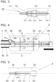
- FIG. 2 shows a partially cut schematic side view of a pulling nozzle comprising a camera adapter and a camera module, wherein an extension sleeve is not necessary, because the length of the camera adapter is adapted to the length of the pulling nozzle.
- FIG. 3 shows a schematic partially cut side view of the camera adapter according to FIG. 2 .
- FIG. 4 shows a partially cut schematic side view of a multipart pipe cleaning and/or inspection nozzle in the form of a rotating nozzle comprising camera module, wherein, in addition to the camera adapter, an extension sleeve is arranged so as to run concentrically to the interior space of the rotating nozzle.
- FIG. 5 shows a schematic partially cut side view of the extension sleeve according to FIG. 4 .
- the pipe cleaning nozzles and/or inspection nozzles 2 of interest here have at least one nozzle body 20 , to which a high-pressure hose 1 can be connected.
- the pipe cleaning nozzle and/or inspection nozzle 2 can be moved parallel to the longitudinal axis L in the feed direction, as suggested by means of the black arrow.
- a camera adapter 23 to which a camera module 24 can be fastened directly or indirectly, is arranged in an interior space, to which pressure medium can be applied.
- the camera module 24 is supplied with energy from the hose wall 10 with electrical contact and/or electrical conductors 11 through the high-pressure hose 1 , or data signals from the camera module 24 are guided away from the pipe cleaning nozzle and/or inspection nozzle 2 , respectively.
- the camera adapter 23 or the length thereof, respectively, is adapted to the length of the pulling nozzle 2 in FIG. 2 .
- the camera adapter 23 has, on its high-pressure hose-side end, a loop contact 231 , which is formed something like a whisk here.
- the loop contact 231 is fastened to a metallic adapter body 233 by means of an insulator insert 232 .
- An inner power line/signal line 234 is connected to the insulator insert 232 , electrically connected to the loop contact 231 and protruding through an interior space of the adapter body 233 in a camera module direction. Electrical power and/or data signals can thus be guided all the way into a camera module 24 , accepted by the loop contact 231 .
- the length of the camera adapter 23 in the direction of the longitudinal axis L is adapted to a pulling nozzle 2 or the corresponding nozzle body 20 , respectively.
- the adapter body 233 is made of metal and has, consecutively in the direction of the longitudinal axis L, a first external thread 2331 , a stop 2332 , a second external thread 2333 , a flange 2334 , and a sleeve 2335 .
- the camera adapter 23 is fastened in the interior space of the nozzle body 20 or in the interior space of a stator part 202 , respectively, by means of the second external thread 2333 .
- the camera module 24 is screwed or attached to the sleeve 2335 , which protrudes later, and the camera module 24 is contacted with the inner power/signal line 234 .
- the stop 2332 can be forgone, whereby the thread diameters of the first external thread 2331 and second external thread 2333 have to be different.
- the diameter in the region of the first external thread 2331 has to be smaller than the diameter of the second external thread 2333 .
- the flange 2334 serves the purpose that the camera adapter 23 cannot be sunk too far in the interior space of the nozzle body 20 .
- a screw connection between camera adapter 23 and nozzle body 20 is advantageous, although a plug connection would likewise be possible.
- the camera adapter 23 can then no longer supply the desired cabling between high-pressure hose 1 and camera module 24 .
- the nozzle body 20 comprises a pushing part 200 , a rotor part 201 , and a stator part 202 .
- the camara adapter 23 or the loop contact 231 thereof, respectively, can no longer be contacted directly with the electrical contact 11 in the high-pressure hose 1 .
- a modular setup comprising camera adapter 23 and an extension sleeve 3 is introduced here. Due to the extension sleeve 3 , which is fastened to the camera adapter 23 by means of a screw connection, an electrical conductor 11 , which is oriented towards the nozzle 2 on the high-pressure hose side, can be contacted indirectly via the extension sleeve 3 and the camera adapter 23 comprising the camera module 24 .
- Different camera adapters 23 of different lengths which are produced in a rather complex manner, do not need to be used for nozzles 2 or nozzle bodies 20 , respectively, of different lengths, but the extension sleeve 3 is available in different lengths and can be variably installed.
- the extension sleeve 3 is installed into the interior space of the pipe cleaning nozzle and/or inspection nozzle 2 and is fastened indirectly therein.
- a non-positive and/or positive respectively a form-fitting and/or force-locking connection of the extension sleeve 3 with the camera adapter 23 is provided in the nozzle body 20 .
- the camera adapter 23 is likewise fastened in a positive and/or non-positive respectively in a form-fitting and/or force-locking manner in the interior space of the nozzle body 20 , so that the connections can be released if necessary.
- the extension sleeve 3 has a high-pressure line section 30 , an outlet section 31 , and a coupling section 32 .
- the high-pressure line section 30 comprises a sleeve loop contact 300 , which can likewise be designed as sleeve whisk, and a sleeve insulator insert 301 .
- the sleeve loop contact 300 comprises one or several bent wire loops, which are electrically conductive.
- the sleeve insulator insert 301 is embedded into the extension sleeve 3 and ensures an electrical insulation of the sleeve loop contact 300 and of at least one centric inner power/signal line 311 with respect to the extension sleeve 3 . In the installed state, the centric inner power/signal line 311 transfers electrical voltages and/or data signals to the loop contact 231 of the camera adapter 23 .
- At least one outlet opening 310 is provided in the extension sleeve 3 , through which pressure medium can be discharged from the interior space radially to the outside from the nozzle 2 .
- the pressure medium is guided to the outside through at least one feed nozzle 21 and/or cleaning nozzle 22 . Due to the fact that the extension sleeve 3 is arranged in the interior space, a centric duct in the nozzle 2 , which guides pressure medium, pressure medium is accordingly guided through the interior of the extension sleeve 3 .
- the diameter of the high-pressure line section 30 and of the outlet section 31 is selected to be smaller than the diameter of the coupling section 32 here.
- the extension sleeve 3 is partially pushed over the camera adapter 23 and is preferably fastened in a screwed manner. An attaching and a clamping fastening of the extension sleeve 3 with the coupling section 32 thereof to the camera adapter 23 on the side thereof facing the high-pressure hose are likewise possible.
- the coupling section 32 preferably has a coupling internal thread 320 , by means of which the coupling section 32 and thus the extension sleeve 3 is screwed onto the camera adapter 23 .
- the electrically conductive extension sleeve 3 is connected in an electrically conductive manner to the camera adapter 23 and the stator part 202 and thus in an electrically conductive manner to the nozzle body 20 .
- the coupling internal thread 320 can be forgone.
- the inner power/signal line 311 is contacted in an electrically conductive manner with the inner power/signal line 234 of the camera adapter 23 , and the inner power/signal line 311 and the inner power/signal line 234 are arranged in an electrically insulated manner with respect to the nozzle body 20 , the camera adapter 23 , and the extension sleeve 3 .
- the extension sleeve 3 is made of steel, aluminum, or of brass.
- the sleeve insulator insert 301 is likewise formed in a sleeve-like manner, comprising a smaller cross section than the high-pressure line section 30 of the extension sleeve 3 .
- the electrically insulating material of the sleeve insulator insert 301 can be ceramic or plastic.
- the sleeve loop contact 300 is fastened in the sleeve insulator insert 301 and is connected to the inner power/signal line 311 , for example by means of soldering. An electrical connection of the sleeve loop contact 300 and the inner power/signal line 311 to the body of the extension sleeve 3 is thus ruled out.
- the extension sleeve 3 is designed with a smaller cross section than in the remaining regions of the extension sleeve 3 and thus in a tapered manner.
- an external thread 300 a is provided at the outer surface of the high-pressure line section 30 .
- a further extension sleeve 3 can be screwed onto the first extension sleeve 3 by means of the tapering and the external thread 300 a.
- An interior space of any length of a nozzle 2 can thus be bridged by several extension sleeves 3 , wherein a power supply and/or data connection from the high-pressure hose side all the way to the camera module 24 is possible.
- the camera module 24 can be supplied with power and/or data signals can be accepted.
Landscapes
- Engineering & Computer Science (AREA)
- Mechanical Engineering (AREA)
- General Engineering & Computer Science (AREA)
- Chemical & Material Sciences (AREA)
- Combustion & Propulsion (AREA)
- Physics & Mathematics (AREA)
- General Physics & Mathematics (AREA)
- Investigating Materials By The Use Of Optical Means Adapted For Particular Applications (AREA)
- Studio Devices (AREA)
Abstract
Description
-
- 1 high-pressure hose
- 10 hose wall with electrical contact
- 11 electrical conductor through high-pressure hose/in hose wall
- 2 pipe cleaning nozzle and/or inspection nozzle
- 20 nozzle body
- 200 pushing part
- 201 rotor part
- 202 stator part/head
- 21 feed nozzle (at least 1)
- 22 cleaning nozzle (at least 1)
- 23 camera adapter
- 231 loop contact/whisk
- 232 insulator insert/loop holder
- 233 adapter body
- 2331 first external thread
- 2332 stop
- 2333 second external thread
- 2334 flange
- 2335 sleeve
- 234 inner power/signal line
- 24 camera module
- 20 nozzle body
- 3 extension sleeve (for camera adapter)
- 30 high-pressure line section
- 300 sleeve loop contact/sleeve whisk
- 300 a external thread
- 301 sleeve insulator insert
- 31 outlet section (centrically)
- 310 outlet opening
- 311 inner power/signal line
- 32 coupling section
- 320 coupling external thread
- 30 high-pressure line section
- L longitudinal axis
- 1 high-pressure hose
Claims (7)
Applications Claiming Priority (2)
| Application Number | Priority Date | Filing Date | Title |
|---|---|---|---|
| CH000139/2020A CH717117B1 (en) | 2020-02-07 | 2020-02-07 | Inspection nozzle with an extension sleeve and extension sleeve. |
| CH00139/20 | 2020-02-07 |
Publications (2)
| Publication Number | Publication Date |
|---|---|
| US20210245207A1 US20210245207A1 (en) | 2021-08-12 |
| US11975367B2 true US11975367B2 (en) | 2024-05-07 |
Family
ID=74644356
Family Applications (1)
| Application Number | Title | Priority Date | Filing Date |
|---|---|---|---|
| US17/155,993 Active 2042-05-07 US11975367B2 (en) | 2020-02-07 | 2021-01-22 | Pipe cleaning and/or pipe inspection nozzle including extension sleeve |
Country Status (4)
| Country | Link |
|---|---|
| US (1) | US11975367B2 (en) |
| CN (1) | CN216573645U (en) |
| CH (1) | CH717117B1 (en) |
| DE (1) | DE202021100077U1 (en) |
Families Citing this family (1)
| Publication number | Priority date | Publication date | Assignee | Title |
|---|---|---|---|---|
| CN117840150B (en) * | 2024-03-06 | 2024-05-31 | 中建安装集团黄河建设有限公司 | Pipeline upset inside lining inner wall clearance ware |
Citations (14)
| Publication number | Priority date | Publication date | Assignee | Title |
|---|---|---|---|---|
| JPH11114513A (en) * | 1997-10-13 | 1999-04-27 | Kantool:Kk | High pressure jet cleaning equipment with camera for piping |
| EP1147825A1 (en) * | 2000-04-07 | 2001-10-24 | ROV Developpement | Video inspection and jet cleaning device for pipes |
| WO2006127095A1 (en) * | 2005-05-25 | 2006-11-30 | Thomas Stoneman | Simultaneously clean and inspect sewer pipes |
| CH699422B1 (en) * | 2006-10-27 | 2010-03-15 | Enz Technik Ag | Cleaning nozzle with braked rotor part. |
| WO2014000887A1 (en) * | 2012-06-27 | 2014-01-03 | Plaesier Arnold | Rotating device and pipe flushing and inspection system |
| DE202014100229U1 (en) * | 2013-03-11 | 2014-01-31 | Enz Technik Ag | Cleaning nozzle for receiving a camera module |
| US20150331136A1 (en) * | 2010-02-22 | 2015-11-19 | Jeffrey S. Tinlin | Inline jet-sonde |
| US20160129458A1 (en) * | 2014-11-11 | 2016-05-12 | Enz Technik Ag | Cleaning nozzle with eddy current brake system |
| US20160305891A1 (en) * | 2010-03-26 | 2016-10-20 | SeeScan, Inc. | Pipe inspection system with jetter push-cable |
| US20170128989A1 (en) * | 2010-03-26 | 2017-05-11 | SeeScan, Inc. | Methods and apparatus for clearing obstructions with a jetter push-cable apparatus |
| EP3326727A2 (en) * | 2016-11-29 | 2018-05-30 | RITEC Rohrinspektionstechnik GmbH | Device for the inspection and cleaning of a conduit or pipe section |
| EP3513877A1 (en) * | 2018-01-21 | 2019-07-24 | Michael Layher | Nozzle device for dispensing fluids |
| DE102018110056A1 (en) * | 2018-04-26 | 2019-10-31 | Envirobot GmbH & Co. KG | Sewer cleaning and inspection device and method |
| US20200012182A1 (en) * | 2018-06-18 | 2020-01-09 | SeeScan, Inc. | Multi-dielectric coaxial push-cables and associated apparatus |
-
2020
- 2020-02-07 CH CH000139/2020A patent/CH717117B1/en not_active Application Discontinuation
-
2021
- 2021-01-11 DE DE202021100077.5U patent/DE202021100077U1/en active Active
- 2021-01-22 US US17/155,993 patent/US11975367B2/en active Active
- 2021-02-05 CN CN202120340405.5U patent/CN216573645U/en active Active
Patent Citations (14)
| Publication number | Priority date | Publication date | Assignee | Title |
|---|---|---|---|---|
| JPH11114513A (en) * | 1997-10-13 | 1999-04-27 | Kantool:Kk | High pressure jet cleaning equipment with camera for piping |
| EP1147825A1 (en) * | 2000-04-07 | 2001-10-24 | ROV Developpement | Video inspection and jet cleaning device for pipes |
| WO2006127095A1 (en) * | 2005-05-25 | 2006-11-30 | Thomas Stoneman | Simultaneously clean and inspect sewer pipes |
| CH699422B1 (en) * | 2006-10-27 | 2010-03-15 | Enz Technik Ag | Cleaning nozzle with braked rotor part. |
| US20150331136A1 (en) * | 2010-02-22 | 2015-11-19 | Jeffrey S. Tinlin | Inline jet-sonde |
| US20160305891A1 (en) * | 2010-03-26 | 2016-10-20 | SeeScan, Inc. | Pipe inspection system with jetter push-cable |
| US20170128989A1 (en) * | 2010-03-26 | 2017-05-11 | SeeScan, Inc. | Methods and apparatus for clearing obstructions with a jetter push-cable apparatus |
| WO2014000887A1 (en) * | 2012-06-27 | 2014-01-03 | Plaesier Arnold | Rotating device and pipe flushing and inspection system |
| DE202014100229U1 (en) * | 2013-03-11 | 2014-01-31 | Enz Technik Ag | Cleaning nozzle for receiving a camera module |
| US20160129458A1 (en) * | 2014-11-11 | 2016-05-12 | Enz Technik Ag | Cleaning nozzle with eddy current brake system |
| EP3326727A2 (en) * | 2016-11-29 | 2018-05-30 | RITEC Rohrinspektionstechnik GmbH | Device for the inspection and cleaning of a conduit or pipe section |
| EP3513877A1 (en) * | 2018-01-21 | 2019-07-24 | Michael Layher | Nozzle device for dispensing fluids |
| DE102018110056A1 (en) * | 2018-04-26 | 2019-10-31 | Envirobot GmbH & Co. KG | Sewer cleaning and inspection device and method |
| US20200012182A1 (en) * | 2018-06-18 | 2020-01-09 | SeeScan, Inc. | Multi-dielectric coaxial push-cables and associated apparatus |
Non-Patent Citations (1)
| Title |
|---|
| http://web.archive.org/web/20160605101907/https://www.kaercher.com/us/home-garden/application-tips/pipe-cleaning.html (Year: 2016). * |
Also Published As
| Publication number | Publication date |
|---|---|
| CH717117A2 (en) | 2021-08-16 |
| DE202021100077U1 (en) | 2021-02-01 |
| CN216573645U (en) | 2022-05-24 |
| US20210245207A1 (en) | 2021-08-12 |
| CH717117B1 (en) | 2024-10-15 |
Similar Documents
| Publication | Publication Date | Title |
|---|---|---|
| US7163420B2 (en) | Compression connector with integral coupler | |
| US11975367B2 (en) | Pipe cleaning and/or pipe inspection nozzle including extension sleeve | |
| US20050014410A1 (en) | Cable connector for welder or wire feeder | |
| KR102773936B1 (en) | Exchange method of porcelain bushing for termination connection box using synthetic fibers | |
| US4458976A (en) | Terminal and connector assembly for electrical cables | |
| CN211351683U (en) | Middle-high voltage cable intermediate joint | |
| CN108886215B (en) | electrical plug connection | |
| US12397310B2 (en) | Extension sleeve for a camera adapter and nozzle having the extension sleeve | |
| EP3403300B1 (en) | Test point adaptor for coaxial cable connections | |
| WO2015157269A1 (en) | Replaceable bushing for electrical equipment | |
| KR101139531B1 (en) | Apparatus for cable connecting | |
| CN215896839U (en) | Automobile wire harness convenient to butt joint | |
| WO2005004290A1 (en) | Coaxial connector | |
| CN113517578A (en) | Radio frequency cable quick connector | |
| GB2256097A (en) | Coupling for braided cable | |
| US20240337159A1 (en) | Connector arrangement, drilling arrangement and method for high voltage electro pulse drilling | |
| CN113422263B (en) | Coaxial cable connector assembly and working method thereof | |
| KR100678538B1 (en) | Coupling devices for welding cables | |
| CN100533869C (en) | An electrical connector | |
| WO2024052661A1 (en) | Harness | |
| RU38355U1 (en) | CABLE LUG | |
| CN106450917A (en) | Side outgoing charging socket and connector | |
| CN112886323B (en) | Intermediate connection device and method for insulated tubular busbars in railway traction power supply systems | |
| CN106329159A (en) | Connector for wellhead | |
| CN219737735U (en) | Aviation plug disassembly-free detection device |
Legal Events
| Date | Code | Title | Description |
|---|---|---|---|
| AS | Assignment |
Owner name: ENZ TECHNIK AG, SWITZERLAND Free format text: ASSIGNMENT OF ASSIGNORS INTEREST;ASSIGNOR:LENDI, CHRISTOPH;REEL/FRAME:055003/0481 Effective date: 20210107 |
|
| FEPP | Fee payment procedure |
Free format text: ENTITY STATUS SET TO UNDISCOUNTED (ORIGINAL EVENT CODE: BIG.); ENTITY STATUS OF PATENT OWNER: SMALL ENTITY |
|
| FEPP | Fee payment procedure |
Free format text: ENTITY STATUS SET TO SMALL (ORIGINAL EVENT CODE: SMAL); ENTITY STATUS OF PATENT OWNER: SMALL ENTITY |
|
| STPP | Information on status: patent application and granting procedure in general |
Free format text: DOCKETED NEW CASE - READY FOR EXAMINATION |
|
| STPP | Information on status: patent application and granting procedure in general |
Free format text: RESPONSE TO NON-FINAL OFFICE ACTION ENTERED AND FORWARDED TO EXAMINER |
|
| STPP | Information on status: patent application and granting procedure in general |
Free format text: FINAL REJECTION MAILED |
|
| STPP | Information on status: patent application and granting procedure in general |
Free format text: RESPONSE AFTER FINAL ACTION FORWARDED TO EXAMINER |
|
| STPP | Information on status: patent application and granting procedure in general |
Free format text: NOTICE OF ALLOWANCE MAILED -- APPLICATION RECEIVED IN OFFICE OF PUBLICATIONS |
|
| ZAAB | Notice of allowance mailed |
Free format text: ORIGINAL CODE: MN/=. |
|
| STPP | Information on status: patent application and granting procedure in general |
Free format text: PUBLICATIONS -- ISSUE FEE PAYMENT VERIFIED |
|
| STCF | Information on status: patent grant |
Free format text: PATENTED CASE |