US11959930B2 - Automatic analysis apparatus - Google Patents
Automatic analysis apparatus Download PDFInfo
- Publication number
- US11959930B2 US11959930B2 US16/749,172 US202016749172A US11959930B2 US 11959930 B2 US11959930 B2 US 11959930B2 US 202016749172 A US202016749172 A US 202016749172A US 11959930 B2 US11959930 B2 US 11959930B2
- Authority
- US
- United States
- Prior art keywords
- dispensing
- immersion
- probe
- dispensing probe
- specimen
- Prior art date
- Legal status (The legal status is an assumption and is not a legal conclusion. Google has not performed a legal analysis and makes no representation as to the accuracy of the status listed.)
- Active, expires
Links
- 238000004458 analytical method Methods 0.000 title claims description 60
- 239000000523 sample Substances 0.000 claims abstract description 321
- 238000007654 immersion Methods 0.000 claims abstract description 179
- 238000005259 measurement Methods 0.000 claims abstract description 97
- 239000007788 liquid Substances 0.000 claims abstract description 89
- 238000004140 cleaning Methods 0.000 claims description 77
- 238000012545 processing Methods 0.000 description 99
- 239000003153 chemical reaction reagent Substances 0.000 description 86
- 238000010790 dilution Methods 0.000 description 59
- 239000012895 dilution Substances 0.000 description 59
- 230000005284 excitation Effects 0.000 description 29
- 238000003756 stirring Methods 0.000 description 26
- 230000007246 mechanism Effects 0.000 description 25
- 238000001514 detection method Methods 0.000 description 20
- 238000000034 method Methods 0.000 description 13
- 238000011109 contamination Methods 0.000 description 11
- 230000004044 response Effects 0.000 description 11
- 239000011347 resin Substances 0.000 description 10
- 229920005989 resin Polymers 0.000 description 10
- XLYOFNOQVPJJNP-UHFFFAOYSA-N water Chemical compound O XLYOFNOQVPJJNP-UHFFFAOYSA-N 0.000 description 7
- 239000008367 deionised water Substances 0.000 description 5
- 229910021641 deionized water Inorganic materials 0.000 description 5
- FAPWRFPIFSIZLT-UHFFFAOYSA-M Sodium chloride Chemical compound [Na+].[Cl-] FAPWRFPIFSIZLT-UHFFFAOYSA-M 0.000 description 3
- 239000008280 blood Substances 0.000 description 3
- 210000004369 blood Anatomy 0.000 description 3
- 239000000470 constituent Substances 0.000 description 3
- 239000011780 sodium chloride Substances 0.000 description 3
- 238000012360 testing method Methods 0.000 description 3
- 238000002835 absorbance Methods 0.000 description 2
- 238000012742 biochemical analysis Methods 0.000 description 2
- 239000012472 biological sample Substances 0.000 description 2
- 230000008859 change Effects 0.000 description 2
- 238000010586 diagram Methods 0.000 description 2
- -1 e.g. Substances 0.000 description 2
- 239000003219 hemolytic agent Substances 0.000 description 2
- 210000002700 urine Anatomy 0.000 description 2
- 238000010876 biochemical test Methods 0.000 description 1
- 239000012295 chemical reaction liquid Substances 0.000 description 1
- 238000001816 cooling Methods 0.000 description 1
- 230000006870 function Effects 0.000 description 1
- 230000002949 hemolytic effect Effects 0.000 description 1
- 238000003384 imaging method Methods 0.000 description 1
- 238000009413 insulation Methods 0.000 description 1
- 239000004973 liquid crystal related substance Substances 0.000 description 1
- 239000000463 material Substances 0.000 description 1
- 238000012986 modification Methods 0.000 description 1
- 230000004048 modification Effects 0.000 description 1
- 230000003287 optical effect Effects 0.000 description 1
- 238000002360 preparation method Methods 0.000 description 1
- 230000008569 process Effects 0.000 description 1
- 230000001737 promoting effect Effects 0.000 description 1
- 230000009467 reduction Effects 0.000 description 1
- 239000004065 semiconductor Substances 0.000 description 1
Images


Classifications
-
- G—PHYSICS
- G01—MEASURING; TESTING
- G01N—INVESTIGATING OR ANALYSING MATERIALS BY DETERMINING THEIR CHEMICAL OR PHYSICAL PROPERTIES
- G01N35/00—Automatic analysis not limited to methods or materials provided for in any single one of groups G01N1/00 - G01N33/00; Handling materials therefor
- G01N35/10—Devices for transferring samples or any liquids to, in, or from, the analysis apparatus, e.g. suction devices, injection devices
- G01N35/1004—Cleaning sample transfer devices
-
- G—PHYSICS
- G01—MEASURING; TESTING
- G01N—INVESTIGATING OR ANALYSING MATERIALS BY DETERMINING THEIR CHEMICAL OR PHYSICAL PROPERTIES
- G01N35/00—Automatic analysis not limited to methods or materials provided for in any single one of groups G01N1/00 - G01N33/00; Handling materials therefor
- G01N35/02—Automatic analysis not limited to methods or materials provided for in any single one of groups G01N1/00 - G01N33/00; Handling materials therefor using a plurality of sample containers moved by a conveyor system past one or more treatment or analysis stations
- G01N35/025—Automatic analysis not limited to methods or materials provided for in any single one of groups G01N1/00 - G01N33/00; Handling materials therefor using a plurality of sample containers moved by a conveyor system past one or more treatment or analysis stations having a carousel or turntable for reaction cells or cuvettes
-
- G—PHYSICS
- G01—MEASURING; TESTING
- G01N—INVESTIGATING OR ANALYSING MATERIALS BY DETERMINING THEIR CHEMICAL OR PHYSICAL PROPERTIES
- G01N35/00—Automatic analysis not limited to methods or materials provided for in any single one of groups G01N1/00 - G01N33/00; Handling materials therefor
- G01N35/00584—Control arrangements for automatic analysers
- G01N35/00594—Quality control, including calibration or testing of components of the analyser
- G01N35/00613—Quality control
- G01N35/00623—Quality control of instruments
-
- G—PHYSICS
- G01—MEASURING; TESTING
- G01N—INVESTIGATING OR ANALYSING MATERIALS BY DETERMINING THEIR CHEMICAL OR PHYSICAL PROPERTIES
- G01N35/00—Automatic analysis not limited to methods or materials provided for in any single one of groups G01N1/00 - G01N33/00; Handling materials therefor
- G01N35/10—Devices for transferring samples or any liquids to, in, or from, the analysis apparatus, e.g. suction devices, injection devices
- G01N35/1002—Reagent dispensers
-
- G—PHYSICS
- G01—MEASURING; TESTING
- G01N—INVESTIGATING OR ANALYSING MATERIALS BY DETERMINING THEIR CHEMICAL OR PHYSICAL PROPERTIES
- G01N35/00—Automatic analysis not limited to methods or materials provided for in any single one of groups G01N1/00 - G01N33/00; Handling materials therefor
- G01N35/10—Devices for transferring samples or any liquids to, in, or from, the analysis apparatus, e.g. suction devices, injection devices
- G01N35/1009—Characterised by arrangements for controlling the aspiration or dispense of liquids
- G01N35/1011—Control of the position or alignment of the transfer device
-
- G—PHYSICS
- G01—MEASURING; TESTING
- G01N—INVESTIGATING OR ANALYSING MATERIALS BY DETERMINING THEIR CHEMICAL OR PHYSICAL PROPERTIES
- G01N35/00—Automatic analysis not limited to methods or materials provided for in any single one of groups G01N1/00 - G01N33/00; Handling materials therefor
- G01N35/10—Devices for transferring samples or any liquids to, in, or from, the analysis apparatus, e.g. suction devices, injection devices
- G01N35/1009—Characterised by arrangements for controlling the aspiration or dispense of liquids
- G01N35/1016—Control of the volume dispensed or introduced
-
- G—PHYSICS
- G01—MEASURING; TESTING
- G01N—INVESTIGATING OR ANALYSING MATERIALS BY DETERMINING THEIR CHEMICAL OR PHYSICAL PROPERTIES
- G01N35/00—Automatic analysis not limited to methods or materials provided for in any single one of groups G01N1/00 - G01N33/00; Handling materials therefor
- G01N35/10—Devices for transferring samples or any liquids to, in, or from, the analysis apparatus, e.g. suction devices, injection devices
- G01N35/1065—Multiple transfer devices
-
- G—PHYSICS
- G01—MEASURING; TESTING
- G01N—INVESTIGATING OR ANALYSING MATERIALS BY DETERMINING THEIR CHEMICAL OR PHYSICAL PROPERTIES
- G01N35/00—Automatic analysis not limited to methods or materials provided for in any single one of groups G01N1/00 - G01N33/00; Handling materials therefor
- G01N2035/00178—Special arrangements of analysers
- G01N2035/00277—Special precautions to avoid contamination (e.g. enclosures, glove- boxes, sealed sample carriers, disposal of contaminated material)
-
- G—PHYSICS
- G01—MEASURING; TESTING
- G01N—INVESTIGATING OR ANALYSING MATERIALS BY DETERMINING THEIR CHEMICAL OR PHYSICAL PROPERTIES
- G01N35/00—Automatic analysis not limited to methods or materials provided for in any single one of groups G01N1/00 - G01N33/00; Handling materials therefor
- G01N35/02—Automatic analysis not limited to methods or materials provided for in any single one of groups G01N1/00 - G01N33/00; Handling materials therefor using a plurality of sample containers moved by a conveyor system past one or more treatment or analysis stations
- G01N35/04—Details of the conveyor system
- G01N2035/0439—Rotary sample carriers, i.e. carousels
- G01N2035/0441—Rotary sample carriers, i.e. carousels for samples
-
- G—PHYSICS
- G01—MEASURING; TESTING
- G01N—INVESTIGATING OR ANALYSING MATERIALS BY DETERMINING THEIR CHEMICAL OR PHYSICAL PROPERTIES
- G01N35/00—Automatic analysis not limited to methods or materials provided for in any single one of groups G01N1/00 - G01N33/00; Handling materials therefor
- G01N35/02—Automatic analysis not limited to methods or materials provided for in any single one of groups G01N1/00 - G01N33/00; Handling materials therefor using a plurality of sample containers moved by a conveyor system past one or more treatment or analysis stations
- G01N35/04—Details of the conveyor system
- G01N2035/0439—Rotary sample carriers, i.e. carousels
- G01N2035/0443—Rotary sample carriers, i.e. carousels for reagents
-
- G—PHYSICS
- G01—MEASURING; TESTING
- G01N—INVESTIGATING OR ANALYSING MATERIALS BY DETERMINING THEIR CHEMICAL OR PHYSICAL PROPERTIES
- G01N35/00—Automatic analysis not limited to methods or materials provided for in any single one of groups G01N1/00 - G01N33/00; Handling materials therefor
- G01N35/02—Automatic analysis not limited to methods or materials provided for in any single one of groups G01N1/00 - G01N33/00; Handling materials therefor using a plurality of sample containers moved by a conveyor system past one or more treatment or analysis stations
- G01N35/04—Details of the conveyor system
- G01N2035/0439—Rotary sample carriers, i.e. carousels
- G01N2035/0453—Multiple carousels working in parallel
-
- G—PHYSICS
- G01—MEASURING; TESTING
- G01N—INVESTIGATING OR ANALYSING MATERIALS BY DETERMINING THEIR CHEMICAL OR PHYSICAL PROPERTIES
- G01N35/00—Automatic analysis not limited to methods or materials provided for in any single one of groups G01N1/00 - G01N33/00; Handling materials therefor
- G01N35/02—Automatic analysis not limited to methods or materials provided for in any single one of groups G01N1/00 - G01N33/00; Handling materials therefor using a plurality of sample containers moved by a conveyor system past one or more treatment or analysis stations
- G01N35/04—Details of the conveyor system
- G01N2035/0474—Details of actuating means for conveyors or pipettes
- G01N2035/0475—Details of actuating means for conveyors or pipettes electric, e.g. stepper motor, solenoid
-
- G—PHYSICS
- G01—MEASURING; TESTING
- G01N—INVESTIGATING OR ANALYSING MATERIALS BY DETERMINING THEIR CHEMICAL OR PHYSICAL PROPERTIES
- G01N35/00—Automatic analysis not limited to methods or materials provided for in any single one of groups G01N1/00 - G01N33/00; Handling materials therefor
- G01N35/10—Devices for transferring samples or any liquids to, in, or from, the analysis apparatus, e.g. suction devices, injection devices
- G01N35/1009—Characterised by arrangements for controlling the aspiration or dispense of liquids
- G01N2035/1025—Fluid level sensing
-
- G—PHYSICS
- G01—MEASURING; TESTING
- G01N—INVESTIGATING OR ANALYSING MATERIALS BY DETERMINING THEIR CHEMICAL OR PHYSICAL PROPERTIES
- G01N35/00—Automatic analysis not limited to methods or materials provided for in any single one of groups G01N1/00 - G01N33/00; Handling materials therefor
- G01N35/10—Devices for transferring samples or any liquids to, in, or from, the analysis apparatus, e.g. suction devices, injection devices
- G01N2035/1027—General features of the devices
- G01N2035/1032—Dilution or aliquotting
Definitions
- the present invention relates to an automatic analysis apparatus.
- An automatic analysis apparatus is used for testing in various fields including biochemical test and blood transfusion test.
- the automatic analysis apparatus performs analysis processing on a large number of specimens simultaneously and analyzes multiple components quickly and precisely.
- the automatic analysis apparatus includes a dispensing probe that sucks and discharges, i.e., dispenses, a liquid, e.g., a specimen or a reagent.
- the automatic analysis apparatus described in JP 2014-A includes a measurement portion, a determination portion, and a notification portion.
- the measurement portion measures a physical quantity that reflects capacitance between a nozzle, which is one electrode, and a container filled with a liquid, which is the other electrode, when the nozzle (dispensing probe) is outside the liquid.
- the determination portion determines whether dirt is adhered to the nozzle on the basis of results of a comparison between the measured physical quantity and a predetermined value.
- the notification portion gives a notice of the result determined by the determination portion.
- JP 2014-194351 A does not describe processing in the case of excessive immersion in which immersion of the dispensing probe exceeds a predetermined range. Moreover, a subsequent operation in the case where immersion of the dispensing probe is excessive immersion varies with use of the automatic analysis apparatus. Therefore, in the case where immersion of the dispensing probe is excessive immersion, an optimal operation is not executed in some cases.
- an automatic analysis apparatus includes a measurement portion, an excessive immersion determination portion, a setting input portion, and a control portion.
- the measurement portion includes a containment unit including a plurality of containers containing a liquid, a dispensing unit including a dispensing probe for dispensing the liquid, and a gauging portion for gauging the liquid dispensed by the dispensing unit.
- the excessive immersion determination portion determines whether an immersion of the dispensing probe is excessive immersion that exceeds a predetermined range.
- the setting input portion can select and set an operation of the measurement portion to be performed after the excessive immersion determination portion determines that the immersion is excessive immersion from a plurality of modes.
- the control portion controls the measurement portion depending on a mode set by the setting input portion.
- the automatic analysis apparatus of the present invention can perform an operation depending on use when immersion of the dispensing probe is excessive immersion.
- FIG. 1 is a schematic configuration view illustrating an automatic analysis apparatus according to a first embodiment of the present invention
- FIG. 2 is a block diagram of the automatic analysis apparatus according to the first embodiment of the present invention.
- FIG. 3 is a perspective view illustrating a dispensing unit according to the first embodiment of the present invention.
- FIG. 4 is a cross-sectional view illustrating a dispensing probe of the dispensing unit according to the first embodiment of the present invention
- FIG. 5 is an explanatory view for explaining excessive immersion of the dispensing probe according to the present invention.
- FIG. 6 is a graph illustrating a first example of an output signal of a liquid surface sensor according to the present invention.
- FIG. 7 is an explanatory view for explaining lowering operation of the dispensing probe according to the present invention.
- FIG. 8 is a graph illustrating a second example of an output signal of a liquid surface sensor according to the present invention.
- FIG. 9 is a graph for explaining movement distance of the dispensing probe according to the present invention.
- FIG. 10 is a graph for explaining immersion distance of the dispensing probe according to the present invention.
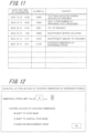
- FIG. 11 is a view illustrating an example of alarm history according to the first embodiment of the present invention.
- FIG. 12 is a view illustrating an example of a control setting screen in the case of excessive immersion of the dispensing probe according to the first embodiment of the present invention.
- FIG. 13 is a flowchart illustrating an example of dispensing processing according to the first embodiment of the present invention.
- FIG. 14 is a flowchart illustrating an example of dispensing processing according to the first embodiment of the present invention.
- FIG. 15 is a flowchart illustrating an example of dispensing processing according to the first embodiment of the present invention.
- FIG. 16 is a flowchart illustrating an example of dispensing processing according to the first embodiment of the present invention.
- FIG. 17 is a flowchart illustrating an example of dispensing processing according to the first embodiment of the present invention.
- FIG. 18 is a flowchart illustrating an example of processing in which special cleaning is performed in S 16 of the dispensing processing according to the first embodiment of the present invention.
- FIG. 19 is a flowchart illustrating an example of dispensing processing according to a second embodiment of the present invention.
- FIG. 20 is a flowchart illustrating an example of dispensing processing according to the second embodiment of the present invention.
- FIG. 21 is a flowchart illustrating an example of dispensing processing according to the second embodiment of the present invention.
- FIG. 22 is a flowchart illustrating an example of dispensing processing according to the second embodiment of the present invention.
- FIG. 23 is a flowchart illustrating an example of dispensing processing according to the second embodiment of the present invention.
- FIG. 24 is a flowchart illustrating an example of dispensing processing according to the second embodiment of the present invention.
- FIG. 25 is a view illustrating an example of a control setting screen depending on an immersion range of a dispensing probe according to a third embodiment of the present invention.
- FIG. 1 is a schematic configuration view illustrating an automatic analysis apparatus according to the first embodiment.
- An automatic analysis apparatus 1 illustrated in FIG. 1 is, for example, a biochemical analysis apparatus that automatically measures the amount of a specific component contained in a biological sample, e.g., blood or urine.
- the automatic analysis apparatus 1 includes a measurement portion 1 a and a control portion 1 b.
- the measurement portion 1 a includes, for example, a sample turntable 2 , a dilution turntable 3 , a first reagent turntable 4 , a second reagent turntable 5 , and a reaction turntable 6 . Moreover, the measurement portion 1 a includes a dilution stirring apparatus 11 , a dilution cleaning apparatus 12 , a first reaction stirring apparatus 13 , a second reaction stirring apparatus 14 , a multi-wavelength photometer 15 , and a reaction container cleaning apparatus 16 .
- the measurement portion 1 a includes a specimen dispensing unit 21 , a dilute specimen dispensing unit 22 , a first reagent dispensing unit 23 , a second reagent dispensing unit 24 , and a probe cleaning apparatus 30 .
- the measurement portion 1 a may further include a cleaned container holding portion, which is not illustrated.
- the specimen dispensing unit 21 , the dilute specimen dispensing unit 22 , the first reagent dispensing unit 23 , and the second reagent dispensing unit 24 indicate specific examples of the dispensing units of the present invention.
- control portion 1 b includes a display portion 41 , and includes an input portion, a storage portion, and a control portion, which will be described in detail below. These constituent elements will be described in detail below in order of the measurement portion 1 a and the control portion 1 b.
- the sample turntable 2 is one of holding portions that hold a plurality of containers that stores a dispense liquid.
- the sample turntable 2 is configured to hold a plurality of specimen containers P 2 in rows along the periphery thereof and convey the held specimen containers P 2 in both directions circumferentially.
- the sample turntable 2 is rotatably supported by a drive mechanism, which is not illustrated, along a circumferential direction.
- Each specimen container P 2 held on the sample turntable 2 stores, as a dispense liquid, a specimen to be measured or a control specimen for precision control.
- the sample turntable 2 is configured such that the various specimens to be measured are held in a predetermined position.
- the sample turntable 2 may hold, in addition to the specimen containers P 2 , a dilution liquid container that stores a dilution liquid or a hemolytic agent container that stores a hemolytic agent for performing hemolytic processing.
- the immersion cleaning container is as large as the cleaning bath of the probe cleaning apparatus 30 , which will be described below, or the specimen container P 2 .
- the sample turntable 2 described above may have a function of cooling the held specimen containers P 2 or other containers.
- the dilution turntable 3 is one of holding portions that hold a plurality of containers that stores a dispense liquid.
- the dilution turntable 3 is configured to hold a plurality of dilution containers P 3 along the periphery thereof and convey the held dilution containers P 3 in both directions circumferentially.
- the dilution turntable 3 is rotatably supported by a drive mechanism, which is not illustrated, along a circumferential direction.
- a specimen sucked from the specimen container P 2 arranged on the sample turntable 2 and diluted (hereinafter, the “dilute specimen”) is injected into the dilution container P 3 held on the dilution turntable 3 as a dispense liquid.
- the automatic analysis apparatus 1 may not include the dilution turntable 3 .
- the first reagent turntable 4 holds a plurality of first reagent containers P 4 along the periphery thereof
- the second reagent turntable 5 holds a plurality of second reagent containers P 5 along the periphery thereof
- the first reagent turntable 4 and the second reagent turntable 5 are configured to convey the held first reagent containers P 4 and the held second reagent containers P 5 in both directions circumferentially.
- the first reagent turntable 4 and the second reagent turntable 5 are one of holding portions that hold a plurality of containers that stores a dispense liquid, and are rotatably supported by a drive mechanism, which is not illustrated, along a circumferential direction.
- a first reagent is dispensed as a dispense liquid from a reagent bottle into the plurality of first reagent containers P 4 held on the first reagent turntable 4 .
- a second reagent is dispensed as a dispense liquid from a reagent bottle into the plurality of second reagent containers P 5 held on the second reagent turntable 5 .
- the reaction turntable 6 is arranged between the dilution turntable 3 , the first reagent turntable 4 , and the second reagent turntable 5 .
- the reaction turntable 6 is configured to hold a plurality of reaction containers P 6 along the periphery thereof and convey the held reaction containers P 6 in both directions circumferentially.
- the reaction turntable 6 is rotatably supported by a drive mechanism, which is not illustrated, along a circumferential direction.
- the dilute specimen collected from the dilution container P 3 of the dilution turntable 3 and the first reagent collected form the first reagent container P 4 of the first reagent turntable 4 or the second reagent collected form the second reagent container P 5 of the second reagent turntable 5 are dispensed into the reaction containers P 6 held on the reaction turntable 6 at a predetermined amount. Then, the dilute specimen and the first reagent or the second reagent are stirred and reacted in the reaction container P 6 .
- the reaction turntable 6 described above is configured to keep the temperature of the reaction container P 6 constant at any time with a constant temperature bath, which is not illustrated. Note that when the automatic analysis apparatus 1 does not include the dilution turntable 3 , a specimen collected from the specimen container P 2 of the sample turntable 2 is dispensed into the reaction container P 6 held on the reaction turntable 6 .
- the dilution stirring apparatus 11 is arranged around the dilution turntable 3 .
- the dilution stirring apparatus 11 includes a stirring mechanism and a drive mechanism for driving the stirring mechanism.
- the dilution stirring apparatus 11 inserts a stir bar, which is not illustrated, into the dilution container P 3 held on the dilution turntable 3 and stirs the specimen to be measured and a dilution liquid.
- the dilution cleaning apparatus 12 is arranged around the dilution turntable 3 .
- the dilution cleaning apparatus 12 is an apparatus for cleaning the dilution container P 3 from which the dilute specimen has been sucked by the dilute specimen dispensing unit 22 , which will be described below.
- the first reaction stirring apparatus 13 and the second reaction stirring apparatus 14 are arranged around the reaction turntable 6 .
- the first reaction stirring apparatus 13 and the second reaction stirring apparatus 14 stir the dilute specimen and the first reagent or the second reagent in the reaction container P 6 held on the reaction turntable 6 .
- the first reaction stirring apparatus 13 and the second reaction stirring apparatus 14 include a stirring mechanism and a drive mechanism for driving the stirring mechanism.
- the first reaction stirring apparatus 13 and the second reaction stirring apparatus 14 insert a stir bar, which is not illustrated, into the reaction container P 6 held in a predetermined position on the reaction turntable 6 and stir the dilute specimen (or specimen) and the first reagent or the second reagent, thereby promoting reaction of the dilute specimen and the first reagent or the second reagent.
- the multi-wavelength photometer 15 is a specific example of the gauging portion of the present invention and is arranged to face an outer wall of the reaction turntable 6 around the reaction turntable 6 .
- the multi-wavelength photometer 15 performs optical measurement on the dilute specimen reacted with the first reagent or the second reagent in the reaction container P 6 , outputs the amount of various components of the specimen as absorbance, and detects a reaction state of the dilute specimen.
- the reaction container cleaning apparatus 16 is arranged around the reaction turntable 6 .
- the reaction container cleaning apparatus 16 is an apparatus that cleans the interior of the reaction container P 6 for which test has ended.
- the specimen dispensing unit 21 includes a specimen probe 21 a as a dispensing probe having a small tube shape.
- the specimen dispensing unit 21 is arranged around the sample turntable 2 and the dilution turntable 3 .
- the specimen dispensing unit 21 inserts an end of the specimen probe 21 a the axial direction of which is held vertically into the specimen in the specimen container P 2 held on the sample turntable 2 or into the specimen in the specimen container conveyed by a specimen feed apparatus 100 , which will be described below, with a drive mechanism, which is not illustrated, according to a preset measurement program.
- a predetermined amount of specimen is sucked into the specimen probe 21 a .
- the sample turntable 2 moves the specimen container P 2 held in a predetermined position on the sample turntable 2 to a predetermined specimen collection position in advance.
- the specimen feed apparatus 100 moves the specimen container held on a specimen rack, which will be described below, to a predetermined specimen collection position in advance.
- the specimen dispensing unit 21 inserts the end of the specimen probe 21 a into the dilution container P 3 of the dilution turntable 3 , and discharges the specimen sucked into the specimen probe 21 a and a predetermined amount of dilution liquid (e.g., saline or deionized water) fed from the specimen dispensing unit 21 itself into the dilution container P 3 .
- dilution liquid e.g., saline or deionized water
- the specimen dispensing unit 21 inserts the end of the specimen probe 21 a into the reaction container P 6 of the reaction turntable 6 . Then, the specimen dispensing unit 21 discharges the specimen sucked into the specimen probe 21 a and a predetermined amount of dilution liquid (e.g., saline or deionized water) fed from the specimen dispensing unit 21 itself into the reaction container P 6 .
- dilution liquid e.g., saline or deionized water
- the specimen probe 21 a includes a liquid surface detection mechanism, which is not illustrated.
- the liquid surface detection mechanism is to detect contact between the end of the specimen probe 21 a and the liquid surface, for example, according to capacitance between the liquid surface and the end of the specimen probe 21 a.
- the dilute specimen dispensing unit 22 includes a dilute specimen probe 22 a , which is a dispensing probe having a small tube shape, and is arranged between the dilution turntable 3 and the reaction turntable 6 .
- the dilute specimen dispensing unit 22 according to a preset measurement program, inserts an end of the dilute specimen probe 22 a the axial direction of which is held vertically into the dilution container P 3 of the dilution turntable 3 with a drive mechanism, which is not illustrated.
- the dilute specimen dispensing unit 22 sucks a predetermined amount of dilute specimen through the end of the dilute specimen probe 22 a , which is filled with a dilution liquid, via an air lock.
- the dilute specimen dispensing unit 22 inserts the end of the dilute specimen probe 22 a into the reaction container P 6 of the reaction turntable 6 , and discharges the dilute specimen sucked into the dilute specimen probe 22 a into the reaction container P 6 .
- the automatic analysis apparatus 1 may not necessarily include the dilute specimen dispensing unit 22 .
- the first reagent dispensing unit 23 includes a first reagent probe 23 a as a dispensing probe having a small tube shape.
- the first reagent dispensing unit 23 is arranged between the reaction turntable 6 and the first reagent turntable 4 .
- the first reagent dispensing unit 23 according to a preset measurement program, inserts an end of the first reagent probe 23 a the axial direction of which is held vertically into the first reagent container P 4 of the first reagent turntable 4 with a drive mechanism, which is not illustrated.
- the first reagent dispensing unit 23 sucks a predetermined amount of first reagent through the end of the first reagent probe 23 a , which is filled with a dilution liquid, via an air lock. Moreover, the first reagent dispensing unit 23 inserts the end of the first reagent probe 23 a into the reaction container P 6 of the reaction turntable 6 and discharges the first reagent, which has been sucked into the first reagent probe 23 a , into the reaction container P 6 .
- the second reagent dispensing unit 24 includes a second reagent probe 24 a as a dispensing probe having a small tube shape.
- the second reagent dispensing unit 24 is arranged between the reaction turntable 6 and the second reagent turntable 5 .
- the second reagent dispensing unit 24 according to a preset measurement program, inserts an end of the second reagent probe 24 a the axial direction of which is held vertically into the second reagent container P 5 of the second reagent turntable 5 with a drive mechanism, which is not illustrated.
- the second reagent dispensing unit 24 sucks a predetermined amount of second reagent through the end of the second reagent probe 24 a , which is filled with a dilution liquid, via an air lock. Moreover, the second reagent dispensing unit 24 inserts the end of the second reagent probe 24 a into the reaction container P 6 of the reaction turntable 6 and discharges the second reagent, which has been sucked into the second reagent probe 24 a , into the reaction container P 6 .
- the probe cleaning apparatus 30 is to immerse and clean the specimen probe 21 a of the specimen dispensing unit 21 and is arranged on the track of the movement of the specimen probe 21 a .
- the probe cleaning apparatus 30 is assumed to be provided on the track of the specimen probe 21 a between the sample turntable 2 and the dilution turntable 3 .
- the probe cleaning apparatus 30 includes a cleaning liquid feed pipe and a cleaning bath.
- the cleaning liquid feed pipe feeds a cleaning liquid in the form of shower to the end of the specimen probe 21 a arranged in an upper part of the cleaning bath to clean the outer wall of the specimen probe 21 a.
- the control portion 1 b is connected to the drive mechanisms of the constituent elements and the multi-wavelength photometer 15 , which constitute the aforementioned measurement portion 1 a , and to the specimen feed apparatus 100 for feeding the specimen to the measurement portion 1 a .
- the specimen feed apparatus 100 includes a feed portion for feeding a specimen rack that contains a plurality of (e.g., five) specimens, and a retrieval portion for retrieving the specimen rack for which dispensing processing by the specimen dispensing unit 21 has been performed.
- the specimen feed apparatus 100 includes a conveyance portion for conveying the specimen rack from the feed portion to the retrieval portion, and a barcode reader arranged between the feed portion and a specimen collection position.
- the conveyance portion conveys the specimen rack to a barcode read position of the barcode reader.
- the barcode reader reads barcode information attached to the specimen container. Then, the conveyance portion conveys the specimen rack to the specimen collection position and, when the dispensing processing by the specimen dispensing unit 21 ends, conveys the specimen rack to the retrieval portion.
- FIG. 2 is a block diagram of the automatic analysis apparatus 1 according to the embodiment.
- control portion 1 b includes a display portion 41 , an input portion 42 , a storage portion 43 , and an input/output control portion 44 . Details of these constituent elements are described below.
- the display portion 41 displays results of the measurement by the multi-wavelength photometer 15 , and various setting information or various history information of the automatic analysis apparatus 1 .
- a liquid crystal display apparatus is used as the display portion 41 .
- the display portion 41 also includes an alarm output portion that outputs an alarm.
- the alarm output portion is not limited to the display portion 41 , but may be a speaker, which is not illustrated, or may be both the display portion 41 and the speaker.
- the input portion 42 is an example of the setting input portion of the present invention.
- the input portion 42 receives input related to various settings or other input performed by an operator of the automatic analysis apparatus 1 , and outputs an input signal to the input/output control portion 44 .
- As the input portion 42 for example, a mouse, a keyboard, or a touch panel provided on a display surface of the display portion 41 is used.
- the storage portion 43 includes, for example, a mass storage apparatus, e.g., HDD (hard disk drive) or a semiconductor memory.
- the storage portion 43 stores various programs executed by the input/output control portion 44 , which will be described below, and the aforementioned various setting information or various history information.
- the input/output control portion 44 includes a calculator, e.g., a microcomputer.
- the calculator includes a storage portion, e.g., a CPU (central processing unit), a ROM (read only memory), and a RAM (random access memory), and controls an operation of each portion in the automatic analysis apparatus 1 .
- the input/output control portion 44 includes portions: a display control portion 44 a , a measurement control portion 44 b , an excessive immersion determination portion 44 c , and a cleaning control portion 44 d.
- the display control portion 44 a creates a display screen related to various setting information or various history information of the automatic analysis apparatus 1 in addition to the results of the measurement by the multi-wavelength photometer 15 , and displays the created display screen on the display portion 41 .
- the various setting information and various history information include setting information and history information related to the case of excessive immersion of the dispensing probe.
- the measurement control portion 44 b is an example of the control portion of the present invention.
- the measurement control portion 44 b controls the timing of an operation of each drive mechanism constituting the measurement portion 1 a and controls the timing of measurement of luminous intensity with the multi-wavelength photometer 15 .
- the measurement control portion 44 b controls the specimen dispensing unit 21 to collect the specimens in order in a predetermined cycle from the plurality of specimen containers P 2 held on the sample turntable 2 .
- the measurement control portion 44 b controls the drive mechanisms such that the specimen in each specimen container P 2 held on the sample turntable 2 is diluted to a predetermined concentration, the dilute specimen is mixed and reacted with the first reagent and the second reagent, and the absorbance of the resulting reaction liquid is measured.
- the excessive immersion determination portion 44 c is connected to a liquid surface sensor 45 .
- the liquid surface sensor 45 outputs a signal depending on a contact state of a liquid of the specimen (dispensing) probe to the excessive immersion determination portion 44 c .
- the excessive immersion determination portion 44 c determines whether an immersion of the specimen (dispensing) probe is excessive immersion that exceeds a predetermined range on the basis of the output of the liquid surface sensor 45 .
- the excessive immersion determination portion 44 c when the immersion of the specimen probe is excessive immersion, instructs the display control portion 44 a to output an alarm to the display portion 41 (alarm output portion).
- Such excessive immersion determination portion 44 c determines whether immersion is excessive immersion on the basis of the setting information stored in the storage portion 43 , a signal from the liquid surface sensor 45 provided on the specimen probe 21 a , or the like. Details of determination as to whether immersion is excessive immersion by the excessive immersion determination portion 44 c will be described with respect to an excessive immersion determination method below.
- the cleaning control portion 44 d controls the probe cleaning apparatus 30 and the drive mechanism of the specimen dispensing unit 21 so as to control a cleaning operation of the specimen probe 21 a.
- FIG. 3 is a perspective view illustrating the dispensing unit according to the first embodiment.
- FIG. 4 is a cross-sectional view illustrating the dispensing probe of the dispensing unit according to the first embodiment.
- specimen dispensing unit 21 the dilute specimen dispensing unit 22 , the first reagent dispensing unit 23 , and the second reagent dispensing unit have the same configuration. Therefore, here, a description is given of the specimen dispensing unit 21 .
- the specimen dispensing unit 21 is simply called the dispensing unit 21
- the specimen probe 21 a is simply called the dispensing probe 21 a.
- the dispensing unit 21 includes a drive mechanism 101 , a support arm 102 , the dispensing probe 21 a , a resin tube 104 , and a pump, which is not illustrated.
- the support arm 102 is supported on the drive mechanism 101 so as to be movable in an up-and-down direction and rotatable in a horizontal direction.
- the dispensing probe 21 a is provided at an end of the support arm 102 which is opposite to the end supported on the drive mechanism 101 .
- a drive portion for moving the dispensing probe 21 a via the support arm 102 is provided on the drive mechanism 101 .
- the dispensing probe 21 a is detachably attached to the support arm 102 via a fixation member 105 . Then, the dispensing probe 21 a protrudes downward in the up-and-down direction from the end of the support arm 102 .
- the dispensing probe 21 a includes an inner pipe 107 , an outer pipe 108 , and an insulation member 109 interposed between the inner pipe 107 and the outer pipe 108 .
- the inner pipe 107 includes a conductive member.
- the resin tube 104 made of a material different from that of the inner pipe 107 is connected to an end of the inner pipe 107 on the support arm 102 side. That is, the inner pipe 107 is communicated with the resin tube 104 .
- the resin tube 104 extends to the drive mechanism 101 along the support arm 102 .
- One end of the resin tube 104 is connected to the inner pipe 107 , and the other end is connected to the pump (not illustrated).
- the pump When the pump is driven, the specimen is sucked to the inner pipe 107 via the resin tube 104 , and the sucked specimen is contained in the inner pipe 107 and the resin tube 104 .
- the inner pipe 107 and the resin tube 104 are filled with deionized water, which is system water. Moreover, an air lock is inserted at an end of the inner pipe 107 opposite from the resin tube 104 , i.e., an end that contacts the specimen. Thus, the specimen can be prevented from being mixed with the deionized water by the air lock when the specimen is sucked by the inner pipe 107 .
- liquid preliminarily charged into the inner pipe 107 and the resin tube 104 is not limited to non-conductive deionized water, but conductive saline or other various liquids may be charged.
- the liquid surface sensor 45 (see FIG. 2 ) is connected to the inner pipe 107 and the outer pipe 108 of the dispensing probe 21 a . Then, the liquid surface sensor 45 detects a value of capacitance of the inner pipe 107 and the outer pipe 108 . A value detected by the liquid surface sensor 45 is output to the excessive immersion determination portion 44 c . Then, the excessive immersion determination portion 44 c determines whether an immersion of the specimen (dispensing) probe is excessive immersion that exceeds a predetermined range on the basis of the value (sensor detection value) detected by the liquid surface sensor 45 .
- FIG. 5 is an explanatory view for explaining excessive immersion of the dispensing probe 21 a .
- FIG. 6 is a graph illustrating a first example of an output signal of the liquid surface sensor 45 .
- a region of the dispensing probe 21 a from an end a of the inner pipe 107 to a predetermined distance b is a region that can be cleaned by the aforementioned probe cleaning apparatus 30 .
- the predetermined distance b is shorter than an inner pipe length c, a length of the inner pipe 107 protruding from the outer pipe 108 . Accordingly, the cleanable region of the dispensing probe 21 a is a part of the inner pipe 107 . Then, a region above the predetermined distance b is an uncleanable region.
- a detection potential by the liquid surface sensor 45 becomes high. Then, when an end d of the outer pipe 108 contacts the liquid surface, a detection potential by the liquid surface sensor 45 becomes higher than the detection potential of the case where the end a of the inner pipe 107 contacts the liquid surface.
- the excessive immersion determination portion 44 c determines that immersion is excessive immersion when a detection potential by the liquid surface sensor 45 exceeds the outer pipe detection threshold.
- the outer pipe detection threshold is set to a value higher than the detection potential immediately before contact between the end d of the outer pipe 108 and the liquid surface and a value lower than the detection potential stabilized after the end d of the outer pipe 108 contacts the liquid surface.
- Such first determination method for excessive immersion does not determine that immersion is excessive immersion until the end d of the outer pipe 108 contacts the liquid surface. Therefore, even when the liquid surface is present in the region from the predetermined distance b to the end d of the outer pipe 108 in the uncleanable region, it is not determined that immersion is excessive immersion. Accordingly, the first determination method for excessive immersion generates an undetectable region over which excessive immersion cannot be detected.
- FIG. 7 is an explanatory view for explaining lowering operation of the dispensing probe 21 a .
- FIG. 8 is a graph illustrating a second example of an output signal of the liquid surface sensor 45 .
- FIG. 9 is a graph for explaining movement distance of the dispensing probe 21 a .
- FIG. 10 is a graph for explaining immersion distance of the dispensing probe 21 a.
- the dispensing probe 21 a including the inner pipe 107 and the outer pipe 108 lowers from a lowering start position h to a lowering stop position j, and sucks the specimen. Then, while lowering from the lowering start position h to the lowering stop position j, the end of the inner pipe 107 contacts the liquid surface. As illustrated in FIG. 8 , when the end of the inner pipe 107 contacts the liquid surface, a detection potential by the liquid surface sensor 45 becomes high. Thus, time taken from the lowering start position h until reaching a liquid surface detection position i, which is the position of the liquid surface, is detected (hereinafter the “liquid surface detection time”).
- an immersion distance of the dispensing probe 21 a is calculated on the basis of the time required from the lowering start position h to the lowering stop position j and the liquid surface detection time.
- the horizontal axis of the graph illustrated in FIG. 9 is time, and the vertical axis is speed of the lowering operation of the dispensing probe 21 a .
- an area enclosed by the graph, the x axis (time), and the y axis (speed) illustrated in FIG. 9 is the movement distance of the dispensing probe 21 a (distance from the lowering start position h to the lowering stop position j).
- the liquid surface detection time is substituted into the graph illustrated in FIG. 9 .
- an area on and after the liquid surface detection time (hatched area of FIG. 10 ) is the movement distance of the dispensing probe 21 a on and after the liquid surface detection position i. That is, the excessive immersion determination portion 44 c calculates the area on and after the liquid surface detection time so as to be able to calculate the immersion distance of the dispensing probe 21 a.
- the excessive immersion determination portion 44 c compares the calculated immersion distance of the dispensing probe 21 a with the predetermined distance b, which is a cleanable region, (see FIG. 5 ), and determines that immersion is normal (not excessive immersion) when the immersion distance of the dispensing probe 21 a is equal to or less than the predetermined distance b. Meanwhile, when the immersion distance of the dispensing probe 21 a is greater than the predetermined distance b, the excessive immersion determination portion 44 c determines that immersion is excessive immersion. Thus, in the second determination method for excessive immersion, the immersion distance of the dispensing probe 21 a is calculated. Therefore, undetectable region for which excessive immersion cannot be detected is not generated.
- FIG. 11 is a view illustrating an example of the display portion outputting alarm history.
- an alarm is output to the display portion 41 when various errors are detected or a matter to be reported to the operator is generated.
- Items of the alarm of the present embodiment include date and time of occurrence, alarm No., and content. The alarms are displayed and listed in order of output such that the history of a predetermined number of alarms can be confirmed.
- the box of date and time of occurrence displays year, month, day, and time. Moreover, the box of content displays the content of an alarm. Alarm No. is assigned to each content to be reported. For example, when the dispensing probe 21 a is excessively immersed, alarm No. 13199 is displayed. Thus, the operator can confirm that the dispensing probe 21 a is excessively immersed and the date and time of occurrence of excessive immersion.
- FIG. 12 is a view illustrating an example of a control setting screen in the case of excessive immersion of the dispensing probe 21 a.
- an immersion upper limit value of the dispensing probe 21 a and an operation executed when excessive immersion of the dispensing probe 21 a occurs can be preset on the control setting screen.
- the control setting screen illustrated in FIG. 12 is displayed on the display portion 41 prior to start of analysis by the measurement portion 1 a .
- the operator uses the input portion 42 to set an immersion upper limit value of the dispensing probe 21 a and an operation executed when excessive immersion of the dispensing probe 21 a occurs.
- the immersion upper limit value displays “b” which is the aforementioned cleanable region as an initial value.
- the operator can change the immersion upper limit value depending on the specimen (sample) or measurement content.
- the initial value “b” is the immersion upper limit value.
- the immersion upper limit value may be input with use of up and down arrow buttons displayed on the setting screen, or a numerical value may be input directly.
- the operation executed when excessive immersion of the dispensing probe 21 a occurs includes “shift to stop mode,” “shift to partial stop mode,” and “maintain measurement mode.”
- the operator selects one of “shift to stop mode,” “shift to partial stop mode,” and “maintain measurement mode.”
- the operation executed when excessive immersion of the dispensing probe 21 a occurs is set.
- “maintain measurement mode” in which the dispensing operation of the dispensing probe 21 a is practically continued is an example of the continuation mode of the present invention.
- the measurement mode is a state in which a preparation operation for measurement of the specimen has been completed and measurement of the specimen can be received.
- reception indicates that barcode information (including information of specimen ID) of a specimen container is read with the barcode reader set on the sample turntable 2 or the specimen feed apparatus 100 , measurement instructions are referenced on the basis of the read barcode information, and the measurement instructions are input to the input/output control portion 44 .
- a predetermined dispensing operation is executed according to the measurement instructions.
- the predetermined dispensing operation is completed, the specimen is conveyed to a predetermined position (storage position) away from the dispensing position.
- the stop mode is a state in which the measurement of the specimen cannot be received.
- the reception of measurement of a subsequent specimen and the dispensing operation are stopped, and measurement instructions with respect to the specimen for which the reception has been completed and a predetermined dispensing operation according to the measurement instructions has not been performed are stopped.
- each operation portion of the measurement portion 1 a moves to and stops at a predetermined position (standby position), and shifting to the stop mode is completed.
- the specimen conveyed to the dispensing position during shifting to the stop mode passes the dispensing position and is conveyed to a predetermined position (storage position).
- the partial stop mode is a state in which the operator needs to access the specimen container P 2 or the reagent containers P 4 and P 5 to set or remove the specimen or the reagent, and the related operation portion (at least one or more of the specimen dispensing unit 21 a , sample turntable 2 , the first reagent turntable 4 , and the second reagent turntable 5 ) is temporarily stopped.
- the partial stop mode is maintained until the operator's instruction of restarting the measurement is given.
- the measurement portion 1 a can restart a predetermined dispensing operation and the measurement of the specimen at any time.
- FIGS. 13 to 17 are a flowchart illustrating an example of the dispensing processing according to the first embodiment.
- the operator sets an immersion upper limit value of the dispensing probe 21 a and an operation executed when excessive immersion of the dispensing probe 21 a occurs on the control setting screen in the case of excessive immersion (see FIG. 12 ), and then gives an instruction of analysis start.
- the input/output control portion 44 when an analysis start instruction (S 1 ) is given, determines whether a current mode is the stop mode (S 2 ).
- the input/output control portion 44 moves each unit to the initial position (S 3 ). Then, each unit is cleaned (S 4 ). After processing of S 4 or when it is determined that the current mode is not the stop mode in S 2 (NO in S 2 ), the input/output control portion 44 shifts to the measurement mode (S 5 ).
- the input/output control portion 44 determines whether there is a specimen for which the reception of the measurement of specimen has been completed (received specimen) and a predetermined dispensing operation according to the measurement instructions has not been completed (non-dispensed specimen) (S 6 ). When it is determined that there is no non-dispensed specimen in the received specimens in S 6 (NO in S 6 ), the input/output control portion 44 ends the dispensing processing. Meanwhile, when it is determined that there is a non-dispensed specimen in the received specimens in S 6 (YES in S 6 ), the input/output control portion 44 moves the dispensing probe 21 a to the specimen container P 2 and sucks the specimen with the dispensing probe 21 a (S 7 ).
- the input/output control portion 44 determines whether the dispensing probe 21 a has been immersed over the preset immersion upper limit (excessively immersed) (S 8 ). When it is determined that the dispensing probe 21 a is not immersed over the immersion upper limit in S 8 (NO in S 8 ), the input/output control portion 44 moves the dispensing probe 21 a to the dilution container P 3 and discharges the specimen of the dispensing probe 21 a to the dilution container P 3 (S 9 ).
- the input/output control portion 44 moves the dispensing probe 21 a to the cleaning position (cleaning bath) of the probe cleaning apparatus 30 , and cleans the dispensing probe 21 a (S 10 ).
- the input/output control portion 44 returns the processing to S 6 and repeats the processing from S 6 .
- the input/output control portion 44 outputs an alarm to the display portion 41 (S 11 ). Then, the input/output control portion 44 moves the dispensing probe 21 a to above the specimen container P 2 (S 12 ).
- the input/output control portion 44 determines whether the “maintain measurement mode” is set in the control setting in the case of excessive immersion of the dispensing probe 21 a (S 13 ). When it is determined that “maintain measurement mode” is not set in S 13 (NO in S 13 ), the input/output control portion 44 determines whether “stop probe immediately” is set (S 14 ). Note that setting of “stop probe immediately” may be made in the control setting in the case of excessive immersion or may be made separately from the control setting in the case of excessive immersion.
- the specimen dispensing probe 21 a is not moved to the dilution container P 3 of the dilution turntable 3 , but temporarily stopped above the specimen collection position.
- the input/output control portion 44 moves the dispensing probe 21 a to the dilution container P 3 and discharges the specimen of the dispensing probe 21 a to the dilution container P 3 (S 15 ).
- the input/output control portion 44 moves the dispensing probe 21 a to the cleaning position (cleaning bath) of the probe cleaning apparatus 30 and cleans the dispensing probe 21 a (S 16 ).
- the input/output control portion 44 After the processing of S 16 or when it is determined that “stop probe immediately” is set in S 14 (YES in S 14 ), the input/output control portion 44 checks the control setting in the case of excessive immersion of the dispensing probe 21 a (S 17 ) and performs the set control (operation). When it is determined that “maintain measurement mode” is set by the control setting in the case of excessive immersion of the dispensing probe 21 a in S 17 , the input/output control portion 44 shifts to the processing of S 6 .
- the input/output control portion 44 determines whether the measurement of the dispensed specimen has ended (S 18 ).
- the input/output control portion 44 repeats the processing of S 18 until the measurement of the dispensed specimen ends. That is, the input/output control portion 44 waits until the measurement of the dispensed specimen ends. Then, when it is determined that the measurement of the dispensed specimen has ended in S 18 (YES in S 18 ), the input/output control portion 44 shifts to the stop mode (S 19 ).
- the input/output control portion 44 displays a response selection screen on the display portion 41 (S 21 ).
- the response selection screen displays “shift to measurement mode,” “perform special cleaning,” and “clean manually.” The operator selects any one of the three displayed responses.
- the input/output control portion 44 checks the response selected in the processing of S 21 (S 22 ) and performs the selected response. When it is determined that the response selected on the response selection screen is “perform special cleaning” in S 22 , the input/output control portion 44 determines whether excitation of the dispensing probe 21 a is on (S 23 ).
- the input/output control portion 44 When it is determined that the excitation of the dispensing probe 21 a is not on in S 23 (NO in S 23 ), the input/output control portion 44 turns on the excitation of the dispensing probe 21 a (S 24 ). After the processing of S 24 or when it is determined that the excitation of the dispensing probe 21 a is on in S 23 (YES in S 23 ), the input/output control portion 44 determines whether the dispensing probe 21 a is in the cleaning position (cleaning bath) of the probe cleaning apparatus 30 (S 25 ).
- the input/output control portion 44 moves the dispensing probe 21 a to the cleaning position (S 26 ). After the processing of S 26 or when it is determined that the dispensing probe 21 a is in the cleaning position in S 25 (YES in S 25 ), the input/output control portion 44 performs special cleaning on the dispensing probe 21 a (S 27 ).
- the special cleaning unlike typical cleaning in terms of cleaning time, cleaning range, cleaning liquid, and cleaning process, carefully cleans a wider range as compared with the typical cleaning. Accordingly, the special cleaning can also clean a portion contaminated by excessive immersion of the dispensing probe 21 a.
- the input/output control portion 44 determines whether the outer wall of the dispensing probe 21 a is contaminated (S 28 ).
- a contamination determination portion determines whether the outer wall of the dispensing probe 21 a is contaminated.
- the contamination determination portion determines whether the outer wall of the dispensing probe 21 a is contaminated on the basis of an image of the dispensing probe 21 a output from an imaging portion, which is not illustrated.
- the input/output control portion 44 shifts to the processing of S 21 . Note that, in the case of NO in S 28 , the outer wall of the dispensing probe 21 a is not contaminated. Therefore, the input/output control portion 44 may shift to the processing of S 2 (see FIG. 13 ).
- the input/output control portion 44 determines whether the number of times of contamination determination retry has reached the preset number of times (S 29 ).
- the input/output control portion 44 shifts to the processing of S 27 . Meanwhile, when it is determined that the number of times of contamination determination retry has reached the preset number of times in S 29 (YES in S 29 ), the input/output control portion 44 shifts to the processing of S 21 .
- the input/output control portion 44 determines whether “stop probe immediately” is set (S 30 ).
- the input/output control portion 44 turns off the excitation of the dispensing probe 21 a (S 31 ).
- the dispensing probe 21 a is not moved. Therefore, the specimen attached to the outer wall of the dispensing probe 21 a is prevented from being discharged to other containers, e.g., the dilution container P 3 , or other units.
- the excitation of the dispensing probe 21 a is turned off, safety of the operator who touches the dispensing probe 21 a during cleaning can be protected.
- the operator moves the dispensing probe 21 a to the cleanable position while preventing dripping of the specimen, and cleans the outer wall of the dispensing probe 21 a manually. Moreover, after the processing of S 31 , the input/output control portion 44 shifts to the processing of S 21 .
- the input/output control portion 44 determines whether the excitation of the dispensing probe 21 a is on (S 32 ).
- the input/output control portion 44 When it is determined that the excitation of the dispensing probe 21 a is not on in S 32 (NO in S 32 ), the input/output control portion 44 turns on the excitation of the dispensing probe 21 a (S 33 ). After the processing of S 33 or when it is determined that the excitation of the dispensing probe 21 a is on in S 32 (YES in S 32 ), the input/output control portion 44 moves the dispensing probe 21 a to the cleanable position and turns off the excitation of the dispensing probe 21 a (S 34 ).
- the operator cleans the dispensing probe 21 a manually. Moreover, after the processing of S 34 , the input/output control portion 44 shifts to the processing of S 21 .
- the input/output control portion 44 determines whether the excitation of the dispensing probe 21 a is on (S 35 ).
- the input/output control portion 44 When it is determined that the excitation of the dispensing probe 21 a is not on in S 35 (NO in S 35 ), the input/output control portion 44 turns on the excitation of the dispensing probe 21 a (S 36 ). After the processing of S 36 or when it is determined that the excitation of the dispensing probe 21 a is on in S 35 (YES in S 35 ), the input/output control portion 44 determines whether the dispensing probe 21 a is in the initial position (S 37 ).
- the input/output control portion 44 moves the dispensing probe 21 a to the initial position (S 38 ). After the processing of S 38 , the input/output control portion 44 shifts to the processing of S 2 (see FIG. 13 ).
- FIG. 18 is a flowchart illustrating an example of processing in which the special cleaning is performed in S 16 in the dispensing processing according to the first embodiment.
- the input/output control portion 44 performs the special cleaning of the dispensing probe 21 a (S 41 ).
- the input/output control portion 44 determines whether the outer wall of the dispensing probe 21 a is contaminated (S 42 ). When it is determined that the outer wall of the dispensing probe 21 a is not contaminated in S 42 (NO in S 42 ), the input/output control portion 44 shifts to the processing of S 6 (see FIG. 13 ).
- the input/output control portion 44 determines whether the number of times of contamination determination retry has reached the preset number of times (S 43 ).
- the input/output control portion 44 shifts to the processing of S 42 . Meanwhile, when it is determined that the number of times of contamination determination retry has reached the preset number of times in S 43 (YES in S 43 ), the input/output control portion 44 shifts to the processing of S 17 (see FIG. 14 ).
- control executed in the case of excessive immersion of the dispensing probe 21 a can be selected from a plurality of controls (e.g., “maintain measurement mode,” “shift to stop mode,” “shift to partial stop mode,” and “stop probe immediately”).
- a plurality of controls e.g., “maintain measurement mode,” “shift to stop mode,” “shift to partial stop mode,” and “stop probe immediately”.
- “shift to stop mode” is set as control executed in the case of excessive immersion.
- the specimen of the sample turntable 2 or the specimen feed apparatus 100 can be retrieved immediately, and it is possible to perform measurement with the different analysis apparatus in advance.
- “shift to partial stop mode” is set as control executed in the case of excessive immersion.
- the state of the specimen (sample) and the dispensing probe 21 a can be confirmed in a short period of time, and measurement can be restarted in a short period of time.
- stop probe immediately is set as control executed in the case of excessive immersion.
- “maintain measurement mode” is set as control executed in the case of excessive immersion.
- the dispensing processing of the present embodiment it is determined whether the outer wall of the dispensing probe 21 a is contaminated. Then, when it is determined that the outer wall of the dispensing probe 21 a is not contaminated, the measurement operation is restarted. Thus, it is not necessary for the operator to confirm whether the dispensing probe 21 a is contaminated, enabling a reduction in burden on the operator.
- the automatic analysis apparatus of the second embodiment has the same configuration as the automatic analysis apparatus 1 of the first embodiment, but they are different in terms of the dispensing processing. Therefore, here, the dispensing processing of the second embodiment is described, and the same configuration as the configuration of the automatic analysis apparatus 1 of the first embodiment will not be elaborated.
- FIGS. 19 to 24 are a flowchart illustrating an example of the dispensing processing according to the second embodiment.
- the operator sets an immersion upper limit value of the dispensing probe 21 a on the control setting screen in the case of excessive immersion (see FIG. 12 ) and gives an instruction of analysis start.
- the input/output control portion 44 when an analysis start instruction (S 51 ) is given, determines whether a current mode is the stop mode (S 52 ).
- the input/output control portion 44 moves each unit to the initial position (S 53 ). Then, each unit is cleaned (S 54 ). After the processing of S 54 or when it is determined that the current mode is not the stop mode in S 52 (NO in S 52 ), the input/output control portion 44 shifts to the measurement mode (S 55 ).
- the input/output control portion 44 determines whether there is a non-dispensed specimen in the received specimens (S 56 ). When it is determined that there is no non-dispensed specimen in the received specimens in S 56 (NO in S 56 ), the input/output control portion 44 ends the dispensing processing. Meanwhile, when it is determined that there is a non-dispensed specimen in the received specimens in S 56 (YES in S 56 ), the input/output control portion 44 moves the dispensing probe 21 a to the specimen container P 2 and sucks the specimen with the dispensing probe 21 a (S 57 ).
- the input/output control portion 44 determines whether the dispensing probe 21 a has been immersed over the preset immersion upper limit (excessively immersed) (S 58 ). When it is determined that the dispensing probe 21 a is not immersed over the immersion upper limit in S 58 (NO in S 58 ), the input/output control portion 44 moves the dispensing probe 21 a to the dilution container P 3 and discharges the specimen of the dispensing probe 21 a to the dilution container P 3 (S 59 ).
- the input/output control portion 44 moves the dispensing probe 21 a to the cleaning position (cleaning bath) of the probe cleaning apparatus 30 , and cleans the dispensing probe 21 a (S 60 ).
- the input/output control portion 44 returns the processing to S 56 and repeats the processing from S 56 .
- the input/output control portion 44 outputs an alarm to the display portion 41 (S 61 ). Then, the input/output control portion 44 moves the dispensing probe 21 a to above the specimen container P 2 (S 62 ).
- the input/output control portion 44 determines whether the “stop probe immediately” is set (S 63 ). When it is determined that “stop probe immediately” is not set in S 63 (NO in S 63 ), the input/output control portion 44 moves the dispensing probe 21 a to the dilution container P 3 and discharges the specimen of the dispensing probe 21 a to the dilution container P 3 (S 64 ).
- the input/output control portion 44 moves the dispensing probe 21 a to the cleaning position (cleaning bath) of the probe cleaning apparatus 30 and cleans the dispensing probe 21 a (S 65 ). After the processing of S 65 or when it is determined that “stop probe immediately” is set in S 63 (YES in S 63 ), the input/output control portion 44 shifts to the partial stop mode (S 66 ).
- the input/output control portion 44 displays the control setting screen in the case of excessive immersion of the dispensing probe 21 a on the display portion (S 67 ).
- the control setting screen in the case of excessive immersion of the dispensing probe 21 a displays “shift to stop mode,” “shift to measurement mode,” “perform special cleaning,” and “clean manually.” The operator selects any of the four displayed control (operations).
- the input/output control portion 44 confirms the control (operation) selected in the processing of S 67 (S 68 ), and performs the selected control (operation).
- the input/output control portion 44 determines whether the measurement of the dispensed specimen has ended (S 69 ).
- the input/output control portion 44 repeats the processing of S 69 until the measurement of the dispensed specimen ends. That is, the input/output control portion 44 waits until the measurement of the dispensed specimen ends. Then, when it is determined that the measurement of the dispensed specimen has ended in S 69 (YES in S 69 ), the input/output control portion 44 shifts to the stop mode (S 70 ). After the processing of S 70 , the input/output control portion 44 shifts to the processing of S 67 .
- the input/output control portion 44 determines whether the excitation of the dispensing probe 21 a is on (S 71 ).
- the input/output control portion 44 When it is determined that the excitation of the dispensing probe 21 a is not on in S 71 (NO in S 71 ), the input/output control portion 44 turns on the excitation of the dispensing probe 21 a (S 72 ). After the processing of S 72 or when it is determined that the excitation of the dispensing probe 21 a is on in S 71 (YES in S 71 ), the input/output control portion 44 determines whether the dispensing probe 21 a is in the cleaning position (cleaning bath) of the probe cleaning apparatus 30 (S 73 ).
- the input/output control portion 44 moves the dispensing probe 21 a to the cleaning position (S 74 ). After the processing of S 74 or when it is determined that the dispensing probe 21 a is in the cleaning position in S 73 (YES in S 73 ), the input/output control portion 44 performs the special cleaning on the dispensing probe 21 a (S 75 ).
- the input/output control portion 44 determines whether the outer wall of the dispensing probe 21 a is contaminated (S 76 ). When it is determined that the outer wall of the dispensing probe 21 a is not contaminated in S 76 (NO in S 76 ), the input/output control portion 44 shifts to the processing of S 67 (see FIG. 21 ). Note that, in the case of NO in S 76 , the outer wall of the dispensing probe 21 a is not contaminated. Therefore, the input/output control portion 44 may shift to the processing of S 52 (see FIG. 19 ).
- the input/output control portion 44 determines whether the number of times of contamination determination retry has reached the preset number of times (S 77 ).
- the input/output control portion 44 shifts to the processing of S 75 . Meanwhile, when it is determined that the number of times of contamination determination retry has reached the preset number of times in S 77 (YES in S 77 ), the input/output control portion 44 shifts to the processing of S 67 .
- the input/output control portion 44 determines whether “stop probe immediately” is set (S 78 ).
- the input/output control portion 44 When it is determined that “stop probe immediately” is set (YES in S 78 ) in S 78 , the input/output control portion 44 turns off the excitation of the dispensing probe 21 a (S 79 ). Thus, when “stop probe immediately” is set, the dispensing probe 21 a is not moved. Therefore, the specimen attached to the outer wall of the dispensing probe 21 a is prevented from being discharged to other containers, e.g., the dilution container P 3 , or other units. After the processing of S 79 , the input/output control portion 44 shifts to the processing of S 67 (see FIG. 21 ).
- the operator moves the dispensing probe 21 a to the cleanable position while preventing dripping of the specimen, and cleans the outer wall of the dispensing probe 21 a manually. Moreover, after the processing of S 79 , the input/output control portion 44 shifts to the processing of S 67 (see FIG. 21 ).
- the input/output control portion 44 determines whether the excitation of the dispensing probe 21 a is on (S 80 ).
- the input/output control portion 44 When it is determined that the excitation of the dispensing probe 21 a is not on in S 80 (NO in S 80 ), the input/output control portion 44 turns on the excitation of the dispensing probe 21 a (S 81 ). After the processing of S 81 or when it is determined that the excitation of the dispensing probe 21 a is on in S 80 (YES in S 80 ), the input/output control portion 44 moves the dispensing probe 21 a to the cleanable position and turns off the excitation of the dispensing probe 21 a (S 82 ).
- the operator cleans the dispensing probe 21 a manually. Moreover, after the processing of S 82 , the input/output control portion 44 shifts to the processing of S 67 .
- the input/output control portion 44 determines whether the excitation of the dispensing probe 21 a is on (S 83 ).
- the input/output control portion 44 determines whether the dispensing probe 21 a is in the initial position (S 85 ).
- control executed in the case of excessive immersion of the dispensing probe 21 a can be selected from a plurality of controls (e.g., “maintain measurement mode,” “shift to stop mode,” “shift to partial stop mode,” and “stop probe immediately”).
- a plurality of controls e.g., “maintain measurement mode,” “shift to stop mode,” “shift to partial stop mode,” and “stop probe immediately”.
- control subsequently executed after the dispensing probe 21 a is excessively immersed can be selected. Therefore, even when the use is changed, an optimal operation corresponding to such change can be executed.
- the automatic analysis apparatus of the third embodiment has the same configuration as the automatic analysis apparatus 1 of the first embodiment, but they are different in terms of the dispensing processing S 17 (see FIG. 14 ). Therefore, here, the dispensing processing S 17 of the third embodiment is described, and the same configuration and processing as the configuration and processing of the automatic analysis apparatus 1 of the first embodiment will not be elaborated.
- the input/output control portion 44 After the processing of S 16 or when it is determined that “stop probe immediately” is set in S 14 (YES in S 14 ), the input/output control portion 44 confirms the control setting depending on the immersion range (S 17 ) and performs the set control (operation). When it is determined that “maintain measurement mode” is set in the control setting depending on the immersion range in S 17 , the input/output control portion 44 shifts to the processing of S 6 .
- FIG. 25 is a view illustrating an example of the control setting screen depending on the immersion range of the dispensing probe 21 a.
- the automatic analysis apparatus of the third embodiment presets control depending on the immersion range (immersion distance).
- a first threshold is input to a first immersion distance input box 51
- a second threshold greater than the first threshold is input to a second immersion distance input box 52 .
- a first immersion range (e.g., “less than 40 mm”) is set.
- a pull-down button is provided next to the first immersion range such that control executed in the case of the first immersion range (e.g., “maintain measurement mode”) can be selected from a pull-down list.
- a minimum value e.g., “40” of a second immersion range is displayed.
- a second immersion range e.g., “40 mm or more and less than 70 mm”.
- a pull down button is provided next to the second immersion range such that control executed in the case of the second immersion range (e.g., “shift to partial stop mode”) can be selected from a pull-down list.
- a minimum value e.g., “70”
- the third immersion range e.g., “70 mm or more”
- a pull down button is provided next to the third immersion range such that control executed in the case of the third immersion range (e.g., “shift to stop mode”) can be selected from a pull-down list.
- the present embodiment a description is given of the example in which different controls are set with respect to the three immersion ranges. However, the same control may be set with respect to different immersion ranges in the automatic analysis apparatus of the present invention. Moreover, in the present embodiment, the three immersion ranges are set by the operator. However, a plurality of immersion ranges may be set in advance and the operator may select control corresponding to each immersion range in the automatic analysis apparatus of the present invention.
- control executed in the case of excessive immersion of the dispensing probe 21 a can be selected from a plurality of controls (e.g., “maintain measurement mode,” “shift to stop mode,” “shift to partial stop mode,” and “stop probe immediately”).
- a plurality of controls e.g., “maintain measurement mode,” “shift to stop mode,” “shift to partial stop mode,” and “stop probe immediately”.
- a subsequent control may vary with the immersion range of the dispensing probe 21 a . Therefore, it is possible to perform an operation depending on the state of immersion of the dispensing probe 21 a . Thus, it is possible to more finely set an operation depending on the use.
- the present invention is not limited to the aforementioned embodiments, but various modifications may be made without departing from the gist of the invention stated in the claims.
- the aforementioned embodiments describe the present invention in detail for the sake of easy understanding, and the present invention is not necessarily limited to include all the configurations described.
- a part of the configuration of an embodiment may be replaced with a configuration of another embodiment, and a configuration of another embodiment may be added to the configuration of an embodiment.
- another configuration may be added, deleted or replaced.
- the immersion upper limit value (threshold) of the dispensing probe 21 a is set before start of the dispensing processing.
- the immersion upper limit value may be automatically set by the excessive immersion determination method (presence or absence of undetectable region for which excessive immersion cannot be detected) or on the basis of the cleanable region of the dispensing probe 21 a or the like.
- the dispensing probe 21 a of the specimen dispensing unit 21 by way of example.
- the dispensing probe of the present invention is not limited to those dispensing a specimen (sample), but may be a dispensing probe of another dispensing unit, e.g., the first reagent dispensing unit 23 .
- the present invention is applied to a biochemical analysis apparatus used for analysis of a biological sample, e.g., blood or urine as the automatic analysis apparatus.
- a biological sample e.g., blood or urine
- the present invention is not limited thereto, but may be applied to an apparatus that analyzes other various elements, e.g., water quality or food.
Landscapes
- Chemical & Material Sciences (AREA)
- Analytical Chemistry (AREA)
- Physics & Mathematics (AREA)
- Health & Medical Sciences (AREA)
- Life Sciences & Earth Sciences (AREA)
- Biochemistry (AREA)
- General Health & Medical Sciences (AREA)
- General Physics & Mathematics (AREA)
- Immunology (AREA)
- Pathology (AREA)
- Quality & Reliability (AREA)
- Engineering & Computer Science (AREA)
- Chemical Kinetics & Catalysis (AREA)
- Automatic Analysis And Handling Materials Therefor (AREA)
Abstract
Description
Claims (3)
Applications Claiming Priority (2)
| Application Number | Priority Date | Filing Date | Title |
|---|---|---|---|
| JP2019010417A JP6837086B2 (en) | 2019-01-24 | 2019-01-24 | Automatic analyzer |
| JP2019-010417 | 2019-05-14 |
Publications (2)
| Publication Number | Publication Date |
|---|---|
| US20200241025A1 US20200241025A1 (en) | 2020-07-30 |
| US11959930B2 true US11959930B2 (en) | 2024-04-16 |
Family
ID=69137722
Family Applications (1)
| Application Number | Title | Priority Date | Filing Date |
|---|---|---|---|
| US16/749,172 Active 2041-02-15 US11959930B2 (en) | 2019-01-24 | 2020-01-22 | Automatic analysis apparatus |
Country Status (4)
| Country | Link |
|---|---|
| US (1) | US11959930B2 (en) |
| EP (1) | EP3686605B1 (en) |
| JP (1) | JP6837086B2 (en) |
| CN (1) | CN111474372B (en) |
Families Citing this family (5)
| Publication number | Priority date | Publication date | Assignee | Title |
|---|---|---|---|---|
| WO2017087707A1 (en) * | 2015-11-18 | 2017-05-26 | Beckman Coulter, Inc. | Filtering device for analyzing instrument |
| JP7177596B2 (en) * | 2018-02-27 | 2022-11-24 | シスメックス株式会社 | Specimen measuring device and specimen measuring method |
| JP7008744B2 (en) * | 2020-04-14 | 2022-01-25 | 日本電子株式会社 | Automatic analyzer and control method of automated analyzer |
| WO2022070459A1 (en) * | 2020-09-29 | 2022-04-07 | 株式会社日立ハイテク | Automated analyzer |
| USD993451S1 (en) * | 2020-11-09 | 2023-07-25 | Perkinelmer U.S. Llc | Autosampler carousel assembly |
Citations (10)
| Publication number | Priority date | Publication date | Assignee | Title |
|---|---|---|---|---|
| JPS58174852A (en) | 1982-04-08 | 1983-10-13 | Toshiba Corp | Apparatus for automatically sucking liquid being examined |
| US4586546A (en) * | 1984-10-23 | 1986-05-06 | Cetus Corporation | Liquid handling device and method |
| US20030070498A1 (en) * | 2001-09-06 | 2003-04-17 | Yasuhiro Ohyama | Automatic sample analyzer and its components |
| US20090169432A1 (en) * | 2007-12-28 | 2009-07-02 | Olympus Corporation | Automatic analyzer and dispensing method thereof |
| US20100051060A1 (en) * | 2007-05-11 | 2010-03-04 | Beckman Coulter, Inc. | Nozzle cleaning method, nozzle cleaning device, and automatic analyzer |
| US20100210007A1 (en) * | 2009-02-16 | 2010-08-19 | Kabushiki Kaisha Toshiba | Automatic analyzer |
| US20110174343A1 (en) * | 2008-09-30 | 2011-07-21 | Hitachi High-Technologies Corporation | Automatic analyzer |
| US20120003731A1 (en) * | 2009-03-13 | 2012-01-05 | Beckman Coulter, Inc. | Analyzer and method for washing dispenser probe |
| JP5259550B2 (en) * | 2009-10-27 | 2013-08-07 | 株式会社日立ハイテクノロジーズ | Automatic analyzer and sample dispensing method |
| JP2014194351A (en) | 2013-03-28 | 2014-10-09 | Toshiba Corp | Automatic analyzer |
Family Cites Families (8)
| Publication number | Priority date | Publication date | Assignee | Title |
|---|---|---|---|---|
| CA2384523C (en) * | 1991-03-04 | 2007-01-09 | Bayer Corporation | Automated analyzer |
| US5550059A (en) * | 1994-02-23 | 1996-08-27 | Bayer Corporation | Fluid sensing pipette |
| JP3158054B2 (en) * | 1996-07-19 | 2001-04-23 | 株式会社日立製作所 | Liquid sampling device |
| JP2009041961A (en) * | 2007-08-07 | 2009-02-26 | Olympus Corp | Washing method of probe for handling liquid and analyzer |
| US20120309099A1 (en) * | 2010-01-29 | 2012-12-06 | Hitachi High-Technologies Corporation | Automatic analyzing device |
| JP5570848B2 (en) * | 2010-03-05 | 2014-08-13 | 株式会社東芝 | Automatic analyzer |
| CN101881706B (en) * | 2010-07-05 | 2014-04-02 | 深圳迈瑞生物医疗电子股份有限公司 | Sampling device and method |
| JP6649942B2 (en) * | 2015-02-23 | 2020-02-19 | 株式会社日立ハイテクノロジーズ | Automatic analyzer |
-
2019
- 2019-01-24 JP JP2019010417A patent/JP6837086B2/en active Active
-
2020
- 2020-01-03 EP EP20150230.9A patent/EP3686605B1/en active Active
- 2020-01-22 US US16/749,172 patent/US11959930B2/en active Active
- 2020-01-22 CN CN202010073411.9A patent/CN111474372B/en active Active
Patent Citations (10)
| Publication number | Priority date | Publication date | Assignee | Title |
|---|---|---|---|---|
| JPS58174852A (en) | 1982-04-08 | 1983-10-13 | Toshiba Corp | Apparatus for automatically sucking liquid being examined |
| US4586546A (en) * | 1984-10-23 | 1986-05-06 | Cetus Corporation | Liquid handling device and method |
| US20030070498A1 (en) * | 2001-09-06 | 2003-04-17 | Yasuhiro Ohyama | Automatic sample analyzer and its components |
| US20100051060A1 (en) * | 2007-05-11 | 2010-03-04 | Beckman Coulter, Inc. | Nozzle cleaning method, nozzle cleaning device, and automatic analyzer |
| US20090169432A1 (en) * | 2007-12-28 | 2009-07-02 | Olympus Corporation | Automatic analyzer and dispensing method thereof |
| US20110174343A1 (en) * | 2008-09-30 | 2011-07-21 | Hitachi High-Technologies Corporation | Automatic analyzer |
| US20100210007A1 (en) * | 2009-02-16 | 2010-08-19 | Kabushiki Kaisha Toshiba | Automatic analyzer |
| US20120003731A1 (en) * | 2009-03-13 | 2012-01-05 | Beckman Coulter, Inc. | Analyzer and method for washing dispenser probe |
| JP5259550B2 (en) * | 2009-10-27 | 2013-08-07 | 株式会社日立ハイテクノロジーズ | Automatic analyzer and sample dispensing method |
| JP2014194351A (en) | 2013-03-28 | 2014-10-09 | Toshiba Corp | Automatic analyzer |
Non-Patent Citations (2)
| Title |
|---|
| European Patent Office Examination Report issued in EP20150230.9, dated Sep. 1, 2021. |
| Extended European Search Report issued in EP20150230.9 dated Jun. 24, 2020. |
Also Published As
| Publication number | Publication date |
|---|---|
| CN111474372B (en) | 2024-03-29 |
| JP2020118565A (en) | 2020-08-06 |
| CN111474372A (en) | 2020-07-31 |
| JP6837086B2 (en) | 2021-03-03 |
| EP3686605A1 (en) | 2020-07-29 |
| US20200241025A1 (en) | 2020-07-30 |
| EP3686605B1 (en) | 2025-07-23 |
Similar Documents
| Publication | Publication Date | Title |
|---|---|---|
| US11959930B2 (en) | Automatic analysis apparatus | |
| EP1087231A2 (en) | Automatic analysis apparatus | |
| CN115144601A (en) | Automatic analysis device and automatic analysis method | |
| JP2011128075A (en) | Automatic analyzer, and specimen stirring method and specimen dispensation method of the automatic analyzer | |
| JP2018194301A (en) | Automatic analyzer and method for adjusting the amount of cleaning liquid | |
| US8778686B2 (en) | Automatic analyzer and dispensing method thereof | |
| JP7461963B2 (en) | Automatic analyzer and reagent dispensing method | |
| JP5161592B2 (en) | Automatic analyzer and maintenance method thereof | |
| JP2009036512A (en) | Automatic analyzer | |
| CN110320380B (en) | Automatic analysis device and automatic analysis method | |
| JP2018204962A (en) | Automatic analyzer and program | |
| US20190369130A1 (en) | Automatic Analyzer | |
| JP2018066583A (en) | Automatic analyzer | |
| JP6758821B2 (en) | Automatic analyzer | |
| US11885825B2 (en) | Automated analyzer and method of controlling the automated analyzer | |
| JP2008003057A (en) | Analyzer and analysis method | |
| CN110730910A (en) | Automatic analyzer | |
| JP2018132416A (en) | Autoanalyzer | |
| CN110501515B (en) | Automatic analysis device and automatic analysis method | |
| JP7720410B2 (en) | automatic analyzer | |
| US20250199028A1 (en) | Dispensing Probe Device and Automatic Analysis Device | |
| US20240264190A1 (en) | Automatic analyzer and method for detecting adhesion of liquid droplet to probe | |
| JP5808473B2 (en) | Automatic analyzer | |
| JP5388745B2 (en) | Automatic analyzer | |
| JP2020201159A (en) | Automatic analyzer |
Legal Events
| Date | Code | Title | Description |
|---|---|---|---|
| FEPP | Fee payment procedure |
Free format text: ENTITY STATUS SET TO UNDISCOUNTED (ORIGINAL EVENT CODE: BIG.); ENTITY STATUS OF PATENT OWNER: LARGE ENTITY |
|
| AS | Assignment |
Owner name: JEOL LTD., JAPAN Free format text: ASSIGNMENT OF ASSIGNORS INTEREST;ASSIGNORS:ASAKURA, MAKOTO;YAMASHITA, MINE;NAKAI, CHIKASHI;AND OTHERS;REEL/FRAME:052237/0066 Effective date: 20200217 |
|
| STPP | Information on status: patent application and granting procedure in general |
Free format text: DOCKETED NEW CASE - READY FOR EXAMINATION |
|
| STPP | Information on status: patent application and granting procedure in general |
Free format text: NON FINAL ACTION MAILED |
|
| STPP | Information on status: patent application and granting procedure in general |
Free format text: RESPONSE TO NON-FINAL OFFICE ACTION ENTERED AND FORWARDED TO EXAMINER |
|
| STPP | Information on status: patent application and granting procedure in general |
Free format text: FINAL REJECTION MAILED |
|
| STPP | Information on status: patent application and granting procedure in general |
Free format text: RESPONSE AFTER FINAL ACTION FORWARDED TO EXAMINER |
|
| STPP | Information on status: patent application and granting procedure in general |
Free format text: ADVISORY ACTION MAILED |
|
| STPP | Information on status: patent application and granting procedure in general |
Free format text: DOCKETED NEW CASE - READY FOR EXAMINATION |
|
| STPP | Information on status: patent application and granting procedure in general |
Free format text: NOTICE OF ALLOWANCE MAILED -- APPLICATION RECEIVED IN OFFICE OF PUBLICATIONS |
|
| STPP | Information on status: patent application and granting procedure in general |
Free format text: PUBLICATIONS -- ISSUE FEE PAYMENT VERIFIED |
|
| STCF | Information on status: patent grant |
Free format text: PATENTED CASE |