US11940559B2 - Light detection and range (LIDAR) device with component stacking for coaxial readout without splitter mirror for autonomous driving vehicles - Google Patents
Light detection and range (LIDAR) device with component stacking for coaxial readout without splitter mirror for autonomous driving vehicles Download PDFInfo
- Publication number
- US11940559B2 US11940559B2 US16/216,780 US201816216780A US11940559B2 US 11940559 B2 US11940559 B2 US 11940559B2 US 201816216780 A US201816216780 A US 201816216780A US 11940559 B2 US11940559 B2 US 11940559B2
- Authority
- US
- United States
- Prior art keywords
- light
- collimating lens
- mounting board
- target
- light beam
- Prior art date
- Legal status (The legal status is an assumption and is not a legal conclusion. Google has not performed a legal analysis and makes no representation as to the accuracy of the status listed.)
- Active, expires
Links
- 238000001514 detection method Methods 0.000 title claims abstract description 6
- 230000008447 perception Effects 0.000 claims description 30
- 238000000034 method Methods 0.000 claims description 22
- 239000012141 concentrate Substances 0.000 claims description 6
- 230000008878 coupling Effects 0.000 claims description 4
- 238000010168 coupling process Methods 0.000 claims description 4
- 238000005859 coupling reaction Methods 0.000 claims description 4
- 230000008569 process Effects 0.000 description 13
- 238000004891 communication Methods 0.000 description 9
- 230000004807 localization Effects 0.000 description 9
- 238000002379 ultrasonic velocimetry Methods 0.000 description 8
- 238000010586 diagram Methods 0.000 description 7
- 230000015654 memory Effects 0.000 description 6
- 230000001133 acceleration Effects 0.000 description 5
- 238000012517 data analytics Methods 0.000 description 4
- 230000002085 persistent effect Effects 0.000 description 4
- 238000012545 processing Methods 0.000 description 3
- 230000005540 biological transmission Effects 0.000 description 2
- 230000033001 locomotion Effects 0.000 description 2
- 238000010801 machine learning Methods 0.000 description 2
- 230000009471 action Effects 0.000 description 1
- 230000010267 cellular communication Effects 0.000 description 1
- 230000001413 cellular effect Effects 0.000 description 1
- 230000008859 change Effects 0.000 description 1
- 238000004590 computer program Methods 0.000 description 1
- 230000001419 dependent effect Effects 0.000 description 1
- 238000013461 design Methods 0.000 description 1
- 238000009429 electrical wiring Methods 0.000 description 1
- 230000006870 function Effects 0.000 description 1
- 230000003993 interaction Effects 0.000 description 1
- 238000005259 measurement Methods 0.000 description 1
- 230000007246 mechanism Effects 0.000 description 1
- 238000012986 modification Methods 0.000 description 1
- 230000004048 modification Effects 0.000 description 1
- 230000003287 optical effect Effects 0.000 description 1
- 239000002245 particle Substances 0.000 description 1
- 230000002093 peripheral effect Effects 0.000 description 1
- 230000004044 response Effects 0.000 description 1
- 238000009987 spinning Methods 0.000 description 1
- 239000000126 substance Substances 0.000 description 1
Images


Classifications
-
- G—PHYSICS
- G01—MEASURING; TESTING
- G01S—RADIO DIRECTION-FINDING; RADIO NAVIGATION; DETERMINING DISTANCE OR VELOCITY BY USE OF RADIO WAVES; LOCATING OR PRESENCE-DETECTING BY USE OF THE REFLECTION OR RERADIATION OF RADIO WAVES; ANALOGOUS ARRANGEMENTS USING OTHER WAVES
- G01S7/00—Details of systems according to groups G01S13/00, G01S15/00, G01S17/00
- G01S7/48—Details of systems according to groups G01S13/00, G01S15/00, G01S17/00 of systems according to group G01S17/00
- G01S7/483—Details of pulse systems
- G01S7/484—Transmitters
-
- G—PHYSICS
- G01—MEASURING; TESTING
- G01S—RADIO DIRECTION-FINDING; RADIO NAVIGATION; DETERMINING DISTANCE OR VELOCITY BY USE OF RADIO WAVES; LOCATING OR PRESENCE-DETECTING BY USE OF THE REFLECTION OR RERADIATION OF RADIO WAVES; ANALOGOUS ARRANGEMENTS USING OTHER WAVES
- G01S7/00—Details of systems according to groups G01S13/00, G01S15/00, G01S17/00
- G01S7/48—Details of systems according to groups G01S13/00, G01S15/00, G01S17/00 of systems according to group G01S17/00
- G01S7/481—Constructional features, e.g. arrangements of optical elements
- G01S7/4811—Constructional features, e.g. arrangements of optical elements common to transmitter and receiver
- G01S7/4812—Constructional features, e.g. arrangements of optical elements common to transmitter and receiver transmitted and received beams following a coaxial path
-
- G—PHYSICS
- G01—MEASURING; TESTING
- G01C—MEASURING DISTANCES, LEVELS OR BEARINGS; SURVEYING; NAVIGATION; GYROSCOPIC INSTRUMENTS; PHOTOGRAMMETRY OR VIDEOGRAMMETRY
- G01C21/00—Navigation; Navigational instruments not provided for in groups G01C1/00 - G01C19/00
- G01C21/26—Navigation; Navigational instruments not provided for in groups G01C1/00 - G01C19/00 specially adapted for navigation in a road network
- G01C21/28—Navigation; Navigational instruments not provided for in groups G01C1/00 - G01C19/00 specially adapted for navigation in a road network with correlation of data from several navigational instruments
-
- G—PHYSICS
- G01—MEASURING; TESTING
- G01C—MEASURING DISTANCES, LEVELS OR BEARINGS; SURVEYING; NAVIGATION; GYROSCOPIC INSTRUMENTS; PHOTOGRAMMETRY OR VIDEOGRAMMETRY
- G01C21/00—Navigation; Navigational instruments not provided for in groups G01C1/00 - G01C19/00
- G01C21/26—Navigation; Navigational instruments not provided for in groups G01C1/00 - G01C19/00 specially adapted for navigation in a road network
- G01C21/34—Route searching; Route guidance
-
- G—PHYSICS
- G01—MEASURING; TESTING
- G01S—RADIO DIRECTION-FINDING; RADIO NAVIGATION; DETERMINING DISTANCE OR VELOCITY BY USE OF RADIO WAVES; LOCATING OR PRESENCE-DETECTING BY USE OF THE REFLECTION OR RERADIATION OF RADIO WAVES; ANALOGOUS ARRANGEMENTS USING OTHER WAVES
- G01S13/00—Systems using the reflection or reradiation of radio waves, e.g. radar systems; Analogous systems using reflection or reradiation of waves whose nature or wavelength is irrelevant or unspecified
- G01S13/86—Combinations of radar systems with non-radar systems, e.g. sonar, direction finder
- G01S13/865—Combination of radar systems with lidar systems
-
- G—PHYSICS
- G01—MEASURING; TESTING
- G01S—RADIO DIRECTION-FINDING; RADIO NAVIGATION; DETERMINING DISTANCE OR VELOCITY BY USE OF RADIO WAVES; LOCATING OR PRESENCE-DETECTING BY USE OF THE REFLECTION OR RERADIATION OF RADIO WAVES; ANALOGOUS ARRANGEMENTS USING OTHER WAVES
- G01S13/00—Systems using the reflection or reradiation of radio waves, e.g. radar systems; Analogous systems using reflection or reradiation of waves whose nature or wavelength is irrelevant or unspecified
- G01S13/88—Radar or analogous systems specially adapted for specific applications
- G01S13/93—Radar or analogous systems specially adapted for specific applications for anti-collision purposes
- G01S13/931—Radar or analogous systems specially adapted for specific applications for anti-collision purposes of land vehicles
-
- G—PHYSICS
- G01—MEASURING; TESTING
- G01S—RADIO DIRECTION-FINDING; RADIO NAVIGATION; DETERMINING DISTANCE OR VELOCITY BY USE OF RADIO WAVES; LOCATING OR PRESENCE-DETECTING BY USE OF THE REFLECTION OR RERADIATION OF RADIO WAVES; ANALOGOUS ARRANGEMENTS USING OTHER WAVES
- G01S17/00—Systems using the reflection or reradiation of electromagnetic waves other than radio waves, e.g. lidar systems
- G01S17/02—Systems using the reflection of electromagnetic waves other than radio waves
- G01S17/06—Systems determining position data of a target
- G01S17/46—Indirect determination of position data
- G01S17/48—Active triangulation systems, i.e. using the transmission and reflection of electromagnetic waves other than radio waves
-
- G—PHYSICS
- G01—MEASURING; TESTING
- G01S—RADIO DIRECTION-FINDING; RADIO NAVIGATION; DETERMINING DISTANCE OR VELOCITY BY USE OF RADIO WAVES; LOCATING OR PRESENCE-DETECTING BY USE OF THE REFLECTION OR RERADIATION OF RADIO WAVES; ANALOGOUS ARRANGEMENTS USING OTHER WAVES
- G01S17/00—Systems using the reflection or reradiation of electromagnetic waves other than radio waves, e.g. lidar systems
- G01S17/86—Combinations of lidar systems with systems other than lidar, radar or sonar, e.g. with direction finders
-
- G—PHYSICS
- G01—MEASURING; TESTING
- G01S—RADIO DIRECTION-FINDING; RADIO NAVIGATION; DETERMINING DISTANCE OR VELOCITY BY USE OF RADIO WAVES; LOCATING OR PRESENCE-DETECTING BY USE OF THE REFLECTION OR RERADIATION OF RADIO WAVES; ANALOGOUS ARRANGEMENTS USING OTHER WAVES
- G01S17/00—Systems using the reflection or reradiation of electromagnetic waves other than radio waves, e.g. lidar systems
- G01S17/87—Combinations of systems using electromagnetic waves other than radio waves
-
- G—PHYSICS
- G01—MEASURING; TESTING
- G01S—RADIO DIRECTION-FINDING; RADIO NAVIGATION; DETERMINING DISTANCE OR VELOCITY BY USE OF RADIO WAVES; LOCATING OR PRESENCE-DETECTING BY USE OF THE REFLECTION OR RERADIATION OF RADIO WAVES; ANALOGOUS ARRANGEMENTS USING OTHER WAVES
- G01S17/00—Systems using the reflection or reradiation of electromagnetic waves other than radio waves, e.g. lidar systems
- G01S17/88—Lidar systems specially adapted for specific applications
- G01S17/93—Lidar systems specially adapted for specific applications for anti-collision purposes
- G01S17/931—Lidar systems specially adapted for specific applications for anti-collision purposes of land vehicles
-
- G—PHYSICS
- G01—MEASURING; TESTING
- G01S—RADIO DIRECTION-FINDING; RADIO NAVIGATION; DETERMINING DISTANCE OR VELOCITY BY USE OF RADIO WAVES; LOCATING OR PRESENCE-DETECTING BY USE OF THE REFLECTION OR RERADIATION OF RADIO WAVES; ANALOGOUS ARRANGEMENTS USING OTHER WAVES
- G01S19/00—Satellite radio beacon positioning systems; Determining position, velocity or attitude using signals transmitted by such systems
- G01S19/38—Determining a navigation solution using signals transmitted by a satellite radio beacon positioning system
- G01S19/39—Determining a navigation solution using signals transmitted by a satellite radio beacon positioning system the satellite radio beacon positioning system transmitting time-stamped messages, e.g. GPS [Global Positioning System], GLONASS [Global Orbiting Navigation Satellite System] or GALILEO
- G01S19/42—Determining position
- G01S19/45—Determining position by combining measurements of signals from the satellite radio beacon positioning system with a supplementary measurement
- G01S19/47—Determining position by combining measurements of signals from the satellite radio beacon positioning system with a supplementary measurement the supplementary measurement being an inertial measurement, e.g. tightly coupled inertial
-
- G—PHYSICS
- G01—MEASURING; TESTING
- G01S—RADIO DIRECTION-FINDING; RADIO NAVIGATION; DETERMINING DISTANCE OR VELOCITY BY USE OF RADIO WAVES; LOCATING OR PRESENCE-DETECTING BY USE OF THE REFLECTION OR RERADIATION OF RADIO WAVES; ANALOGOUS ARRANGEMENTS USING OTHER WAVES
- G01S7/00—Details of systems according to groups G01S13/00, G01S15/00, G01S17/00
- G01S7/48—Details of systems according to groups G01S13/00, G01S15/00, G01S17/00 of systems according to group G01S17/00
- G01S7/481—Constructional features, e.g. arrangements of optical elements
- G01S7/4811—Constructional features, e.g. arrangements of optical elements common to transmitter and receiver
- G01S7/4813—Housing arrangements
-
- G—PHYSICS
- G01—MEASURING; TESTING
- G01S—RADIO DIRECTION-FINDING; RADIO NAVIGATION; DETERMINING DISTANCE OR VELOCITY BY USE OF RADIO WAVES; LOCATING OR PRESENCE-DETECTING BY USE OF THE REFLECTION OR RERADIATION OF RADIO WAVES; ANALOGOUS ARRANGEMENTS USING OTHER WAVES
- G01S7/00—Details of systems according to groups G01S13/00, G01S15/00, G01S17/00
- G01S7/48—Details of systems according to groups G01S13/00, G01S15/00, G01S17/00 of systems according to group G01S17/00
- G01S7/483—Details of pulse systems
- G01S7/486—Receivers
-
- G—PHYSICS
- G01—MEASURING; TESTING
- G01S—RADIO DIRECTION-FINDING; RADIO NAVIGATION; DETERMINING DISTANCE OR VELOCITY BY USE OF RADIO WAVES; LOCATING OR PRESENCE-DETECTING BY USE OF THE REFLECTION OR RERADIATION OF RADIO WAVES; ANALOGOUS ARRANGEMENTS USING OTHER WAVES
- G01S15/00—Systems using the reflection or reradiation of acoustic waves, e.g. sonar systems
- G01S15/88—Sonar systems specially adapted for specific applications
- G01S15/93—Sonar systems specially adapted for specific applications for anti-collision purposes
- G01S15/931—Sonar systems specially adapted for specific applications for anti-collision purposes of land vehicles
-
- G—PHYSICS
- G01—MEASURING; TESTING
- G01S—RADIO DIRECTION-FINDING; RADIO NAVIGATION; DETERMINING DISTANCE OR VELOCITY BY USE OF RADIO WAVES; LOCATING OR PRESENCE-DETECTING BY USE OF THE REFLECTION OR RERADIATION OF RADIO WAVES; ANALOGOUS ARRANGEMENTS USING OTHER WAVES
- G01S13/00—Systems using the reflection or reradiation of radio waves, e.g. radar systems; Analogous systems using reflection or reradiation of waves whose nature or wavelength is irrelevant or unspecified
- G01S13/88—Radar or analogous systems specially adapted for specific applications
- G01S13/93—Radar or analogous systems specially adapted for specific applications for anti-collision purposes
- G01S13/931—Radar or analogous systems specially adapted for specific applications for anti-collision purposes of land vehicles
- G01S2013/9316—Radar or analogous systems specially adapted for specific applications for anti-collision purposes of land vehicles combined with communication equipment with other vehicles or with base stations
-
- G—PHYSICS
- G01—MEASURING; TESTING
- G01S—RADIO DIRECTION-FINDING; RADIO NAVIGATION; DETERMINING DISTANCE OR VELOCITY BY USE OF RADIO WAVES; LOCATING OR PRESENCE-DETECTING BY USE OF THE REFLECTION OR RERADIATION OF RADIO WAVES; ANALOGOUS ARRANGEMENTS USING OTHER WAVES
- G01S13/00—Systems using the reflection or reradiation of radio waves, e.g. radar systems; Analogous systems using reflection or reradiation of waves whose nature or wavelength is irrelevant or unspecified
- G01S13/88—Radar or analogous systems specially adapted for specific applications
- G01S13/93—Radar or analogous systems specially adapted for specific applications for anti-collision purposes
- G01S13/931—Radar or analogous systems specially adapted for specific applications for anti-collision purposes of land vehicles
- G01S2013/9318—Controlling the steering
-
- G—PHYSICS
- G01—MEASURING; TESTING
- G01S—RADIO DIRECTION-FINDING; RADIO NAVIGATION; DETERMINING DISTANCE OR VELOCITY BY USE OF RADIO WAVES; LOCATING OR PRESENCE-DETECTING BY USE OF THE REFLECTION OR RERADIATION OF RADIO WAVES; ANALOGOUS ARRANGEMENTS USING OTHER WAVES
- G01S13/00—Systems using the reflection or reradiation of radio waves, e.g. radar systems; Analogous systems using reflection or reradiation of waves whose nature or wavelength is irrelevant or unspecified
- G01S13/88—Radar or analogous systems specially adapted for specific applications
- G01S13/93—Radar or analogous systems specially adapted for specific applications for anti-collision purposes
- G01S13/931—Radar or analogous systems specially adapted for specific applications for anti-collision purposes of land vehicles
- G01S2013/93185—Controlling the brakes
-
- G—PHYSICS
- G01—MEASURING; TESTING
- G01S—RADIO DIRECTION-FINDING; RADIO NAVIGATION; DETERMINING DISTANCE OR VELOCITY BY USE OF RADIO WAVES; LOCATING OR PRESENCE-DETECTING BY USE OF THE REFLECTION OR RERADIATION OF RADIO WAVES; ANALOGOUS ARRANGEMENTS USING OTHER WAVES
- G01S13/00—Systems using the reflection or reradiation of radio waves, e.g. radar systems; Analogous systems using reflection or reradiation of waves whose nature or wavelength is irrelevant or unspecified
- G01S13/88—Radar or analogous systems specially adapted for specific applications
- G01S13/93—Radar or analogous systems specially adapted for specific applications for anti-collision purposes
- G01S13/931—Radar or analogous systems specially adapted for specific applications for anti-collision purposes of land vehicles
- G01S2013/9319—Controlling the accelerator
Definitions
- Embodiments of the present disclosure relate generally to operating autonomous driving vehicles. More particularly, embodiments of the disclosure relate to a LIDAR device utilized in autonomous driving vehicles.
- Vehicles operating in an autonomous mode can relieve occupants, especially the driver, from some driving-related responsibilities.
- the vehicle can navigate to various locations using onboard sensors, allowing the vehicle to travel with minimal human interaction or in some cases without any passengers.
- a LIDAR device can estimate a distance to an object while scanning through a scene to assemble a point cloud representing a reflective surface of the object. Individual points in the point cloud can be determined by transmitting a laser pulse and detecting a returning pulse, if any, reflected from the object, and determining the distance to the object according to the time delay between the transmitted pulse and the reception of the reflected pulse.
- a laser or lasers can be rapidly and repeatedly scanned across a scene to provide continuous real-time information on distances to reflective objects in the scene.
- a traditional LIDAR device typically includes a transmitting and a receiving sensor disposed at different locations of different light paths. It utilizes a light splitter to transmit light from the transmitter and deflect the received light using the splitter mirror to the receiver. Such a configuration tends to be large in size. It is also difficult to align the received light to the receiver. Given that a LIDAR device can have multiple transmitter and receiver pairs, it makes the alignment even harder and the physical size even larger.
- FIG. 1 is a block diagram illustrating a networked system according to one embodiment.
- FIG. 2 is a block diagram illustrating an example of an autonomous vehicle according to one embodiment.
- FIG. 3 is a block diagram illustrating an example of a perception and planning system used with an autonomous vehicle according to one embodiment.
- FIG. 4 shows a typical LIDAR mounting configuration.
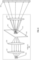
- FIG. 5 shows a perspective view of a transmitting and receiving unit of a LIDAR device according to one embodiment.
- FIGS. 6 A and 6 B show a light transmitting path and a light receiving path respective according to certain embodiment.
- FIG. 7 is a flow diagram illustrating a process of operating a LIDAR device according to one embodiment.
- Embodiments of the invention are to position a light transmitter and a light receiver on the same light path. As a result, the received light can be easily or accurately aligned to a light detector or sensor. In addition, the physical size of the LIDAR device can be made smaller.
- a light detection and range (LIDAR) device includes an array of light transmitting and receiving (TX/RX) units arranged to sense a physical range associated with a target.
- Each of the light TX/RX units includes a mounting board having a light pass-through opening (or window) and a light emitter mounted adjacent to the light pass-through opening.
- the light emitter is configured to emit a light beam towards the target according to a transmitting path.
- the LIDAR device further includes a light detector positioned behind the mounting board to receive at least a portion of the light beam reflected from the target through the light pass-through opening according to a light receiving path.
- the light transmitting path and the light receiving path are substantially in parallel and close to or overlapped with each other, such that the light pass-through opening, as well as the TX/RX unit, can be made smaller.
- each TX/RX unit further includes a first collimating lens disposed between the target and the light emitter.
- the first collimating lens is configured to diverge the light beam from the light emitter towards the target.
- the first collimating lens is further configured to collapse at least a portion of the reflected light beam received from the target, such that the reflected light beam can pass through the light pass-through opening to reach the light detector.
- each light TX/RX unit further includes a second collimating lens positioned between the mounting board and the light detector.
- the second collimating lens is configured to receive the reflected light from the first collimating lens through the pass-through opening of the mounting board and to transform the reflected light from various angles to parallel light towards the light detector.
- each light TX/RX unit further includes a third collimating lens positioned between the second collimating lens and the light detector. The third collimating lens is configured to collapse the light received from the second collimating lens to concentrate and focus onto the light detector.
- an ADV includes a LIDAR device as described above and a perception and planning system.
- the perception and planning system is configured to perceive a driving environment surrounding the ADV based on LIDAR sensor data provided by the LIDAR device and to control the ADV to navigate through the driving environment.
- a process to operating a LIDAR device includes providing an array of light transmitting and receiving (TX/RX) units to sense a physical range associated with a target.
- TX/RX light transmitting and receiving
- the process includes providing a mounting board having a light pass-through opening and emitting a light beam using a light emitter mounted on the mounting board adjacent to the light pass-through opening.
- the light emitter is configured to emit the light beam towards the target according to a transmitting path.
- the process further includes receiving using a light detector positioned behind the mounting board at least a portion of the light beam reflected from the target through the light pass-through opening according to a light receiving path.
- the light transmitting path and the light receiving path are substantially in parallel and close to each other.
- FIG. 1 is a block diagram illustrating an autonomous vehicle network configuration according to one embodiment of the disclosure.
- network configuration 100 includes autonomous vehicle 101 that may be communicatively coupled to one or more servers 103 - 104 over a network 102 .
- network 102 may be any type of networks such as a local area network (LAN), a wide area network (WAN) such as the Internet, a cellular network, a satellite network, or a combination thereof, wired or wireless.
- LAN local area network
- WAN wide area network
- Server(s) 103 - 104 may be any kind of servers or a cluster of servers, such as Web or cloud servers, application servers, backend servers, or a combination thereof.
- Servers 103 - 104 may be data analytics servers, content servers, traffic information servers, map and point of interest (MPOI) servers, or location servers, etc.
- MPOI map and point of interest
- An autonomous vehicle refers to a vehicle that can be configured to in-an autonomous mode in which the vehicle navigates through an environment with little or no input from a driver.
- Such an autonomous vehicle can include a sensor system having one or more sensors that are configured to detect information about the environment in which the vehicle operates. The vehicle and its associated controller(s) use the detected information to navigate through the environment.
- Autonomous vehicle 101 can operate in a manual mode, a full autonomous mode, or a partial autonomous mode.
- autonomous vehicle 101 includes, but is not limited to, perception and planning system 110 , vehicle control system 111 , wireless communication system 112 , user interface system 113 , infotainment system 114 , and sensor system 115 .
- Autonomous vehicle 101 may further include certain common components included in ordinary vehicles, such as, an engine, wheels, steering wheel, transmission, etc., which may be controlled by vehicle control system 111 and/or perception and planning system 110 using a variety of communication signals and/or commands, such as, for example, acceleration signals or commands, deceleration signals or commands, steering signals or commands, braking signals or commands, etc.
- Components 110 - 115 may be communicatively coupled to each other via an interconnect, a bus, a network, or a combination thereof.
- components 110 - 115 may be communicatively coupled to each other via a controller area network (CAN) bus.
- CAN controller area network
- a CAN bus is a vehicle bus standard designed to allow microcontrollers and devices to communicate with each other in applications without a host computer. It is a message-based protocol, designed originally for multiplex electrical wiring within automobiles, but is also used in many other contexts.
- sensor system 115 includes, but it is not limited to, one or more cameras 211 , global positioning system (GPS) unit 212 , inertial measurement unit (IMU) 213 , radar unit 214 , and a light detection and range (LIDAR) unit 215 .
- GPS system 212 may include a transceiver operable to provide information regarding the position of the autonomous vehicle.
- IMU unit 213 may sense position and orientation changes of the autonomous vehicle based on inertial acceleration.
- Radar unit 214 may represent a system that utilizes radio signals to sense objects within the local environment of the autonomous vehicle. In some embodiments, in addition to sensing objects, radar unit 214 may additionally sense the speed and/or heading of the objects.
- LIDAR unit 215 may sense objects in the environment in which the autonomous vehicle is located using lasers.
- LIDAR unit 215 could include one or more laser sources, a laser scanner, and one or more detectors, among other system components.
- Cameras 211 may include one or more devices to capture images of the environment surrounding the autonomous vehicle. Cameras 211 may be still cameras and/or video cameras. A camera may be mechanically movable, for example, by mounting the camera on a rotating and/or tilting a platform.
- Sensor system 115 may further include other sensors, such as, a sonar sensor, an infrared sensor, a steering sensor, a throttle sensor, a braking sensor, and an audio sensor (e.g., microphone).
- An audio sensor may be configured to capture sound from the environment surrounding the autonomous vehicle.
- a steering sensor may be configured to sense the steering angle of a steering wheel, wheels of the vehicle, or a combination thereof.
- a throttle sensor and a braking sensor sense the throttle position and braking position of the vehicle, respectively. In some situations, a throttle sensor and a braking sensor may be integrated as an integrated throttle/braking sensor.
- vehicle control system 111 includes, but is not limited to, steering unit 201 , throttle unit 202 (also referred to as an acceleration unit), and braking unit 203 .
- Steering unit 201 is to adjust the direction or heading of the vehicle.
- Throttle unit 202 is to control the speed of the motor or engine that in turn control the speed and acceleration of the vehicle.
- Braking unit 203 is to decelerate the vehicle by providing friction to slow the wheels or tires of the vehicle. Note that the components as shown in FIG. 2 may be implemented in hardware, software, or a combination thereof.
- wireless communication system 112 is to allow communication between autonomous vehicle 101 and external systems, such as devices, sensors, other vehicles, etc.
- wireless communication system 112 can wirelessly communicate with one or more devices directly or via a communication network, such as servers 103 - 104 over network 102 .
- Wireless communication system 112 can use any cellular communication network or a wireless local area network (WLAN), e.g., using WiFi to communicate with another component or system.
- Wireless communication system 112 could communicate directly with a device (e.g., a mobile device of a passenger, a display device, a speaker within vehicle 101 ), for example, using an infrared link, Bluetooth, etc.
- User interface system 113 may be part of peripheral devices implemented within vehicle 101 including, for example, a keyboard, a touch screen display device, a microphone, and a speaker, etc.
- Perception and planning system 110 includes the necessary hardware (e.g., processor(s), memory, storage) and software (e.g., operating system, planning and routing programs) to receive information from sensor system 115 , control system 111 , wireless communication system 112 , and/or user interface system 113 , process the received information, plan a route or path from a starting point to a destination point, and then drive vehicle 101 based on the planning and control information.
- Perception and planning system 110 may be integrated with vehicle control system 111 .
- Perception and planning system 110 obtains the trip related data.
- perception and planning system 110 may obtain location and route information from an MPOI server, which may be a part of servers 103 - 104 .
- the location server provides location services and the MPOI server provides map services and the POIs of certain locations.
- such location and MPOI information may be cached locally in a persistent storage device of perception and planning system 110 .
- perception and planning system 110 may also obtain real-time traffic information from a traffic information system or server (TIS).
- TIS traffic information system
- servers 103 - 104 may be operated by a third party entity.
- the functionalities of servers 103 - 104 may be integrated with perception and planning system 110 .
- perception and planning system 110 can plan an optimal route and drive vehicle 101 , for example, via control system 111 , according to the planned route to reach the specified destination safely and efficiently.
- Server 103 may be a data analytics system to perform data analytics services for a variety of clients.
- data analytics system 103 includes data collector 121 and machine learning engine 122 .
- Data collector 121 collects driving statistics 123 from a variety of vehicles, either autonomous vehicles or regular vehicles driven by human drivers.
- Driving statistics 123 include information indicating the driving commands (e.g., throttle, brake, steering commands) issued and responses of the vehicles (e.g., speeds, accelerations, decelerations, directions) captured by sensors of the vehicles at different points in time.
- Driving statistics 123 may further include information describing the driving environments at different points in time, such as, for example, routes (including starting and destination locations), MPOIs, road conditions, weather conditions, etc.
- machine learning engine 122 Based on driving statistics 123 , machine learning engine 122 generates or trains a set of rules, algorithms, and/or predictive models 124 for a variety of purposes.
- algorithms 124 may include an algorithm to process LIDAR sensor data for perception using a LIDAR device described throughout this application. Algorithms 124 can then be uploaded on ADVs to be utilized during autonomous driving in real-time.
- FIG. 3 is a block diagram illustrating an example of a perception and planning system used with an autonomous vehicle according to one embodiment.
- System 300 may be implemented as a part of autonomous vehicle 101 of FIG. 1 including, but is not limited to, perception and planning system 110 , control system 111 , and sensor system 115 .
- perception and planning system 110 includes, but is not limited to, localization module 301 , perception module 302 , prediction module 303 , decision module 304 , planning module 305 , control module 306 , and routing module 307 .
- modules 301 - 307 may be implemented in software, hardware, or a combination thereof. For example, these modules may be installed in persistent storage device 352 , loaded into memory 351 , and executed by one or more processors (not shown). Note that some or all of these modules may be communicatively coupled to or integrated with some or all modules of vehicle control system 111 of FIG. 2 . Some of modules 301 - 307 may be integrated together as an integrated module.
- Localization module 301 determines a current location of autonomous vehicle 300 (e.g., leveraging GPS unit 212 ) and manages any data related to a trip or route of a user.
- Localization module 301 (also referred to as a map and route module) manages any data related to a trip or route of a user.
- a user may log in and specify a starting location and a destination of a trip, for example, via a user interface.
- Localization module 301 communicates with other components of autonomous vehicle 300 , such as map and route information 311 , to obtain the trip related data.
- localization module 301 may obtain location and route information from a location server and a map and POI (MPOI) server.
- MPOI map and POI
- a location server provides location services and an MPOI server provides map services and the POIs of certain locations, which may be cached as part of map and route information 311 .
- MPOI server provides map services and the POIs of certain locations, which may be cached as part of map and route information 311 .
- localization module 301 may also obtain real-time traffic information from a traffic information system or server.
- a perception of the surrounding environment is determined by perception module 302 .
- the perception information may represent what an ordinary driver would perceive surrounding a vehicle in which the driver is driving.
- the perception can include the lane configuration, traffic light signals, a relative position of another vehicle, a pedestrian, a building, crosswalk, or other traffic related signs (e.g., stop signs, yield signs), etc., for example, in a form of an object.
- the lane configuration includes information describing a lane or lanes, such as, for example, a shape of the lane (e.g., straight or curvature), a width of the lane, how many lanes in a road, one-way or two-way lane, merging or splitting lanes, exiting lane, etc.
- a shape of the lane e.g., straight or curvature
- a width of the lane how many lanes in a road, one-way or two-way lane, merging or splitting lanes, exiting lane, etc.
- Perception module 302 may include a computer vision system or functionalities of a computer vision system to process and analyze images captured by one or more cameras in order to identify objects and/or features in the environment of autonomous vehicle.
- the objects can include traffic signals, road way boundaries, other vehicles, pedestrians, and/or obstacles, etc.
- the computer vision system may use an object recognition algorithm, video tracking, and other computer vision techniques.
- the computer vision system can map an environment, track objects, and estimate the speed of objects, etc.
- Perception module 302 can also detect objects based on other sensors data provided by other sensors such as a radar and/or LIDAR.
- prediction module 303 predicts what the object will behave under the circumstances. The prediction is performed based on the perception data perceiving the driving environment at the point in time in view of a set of map/rout information 311 and traffic rules 312 . For example, if the object is a vehicle at an opposing direction and the current driving environment includes an intersection, prediction module 303 will predict whether the vehicle will likely move straight forward or make a turn. If the perception data indicates that the intersection has no traffic light, prediction module 303 may predict that the vehicle may have to fully stop prior to enter the intersection. If the perception data indicates that the vehicle is currently at a left-turn only lane or a right-turn only lane, prediction module 303 may predict that the vehicle will more likely make a left turn or right turn respectively.
- decision module 304 makes a decision regarding how to handle the object. For example, for a particular object (e.g., another vehicle in a crossing route) as well as its metadata describing the object (e.g., a speed, direction, turning angle), decision module 304 decides how to encounter the object (e.g., overtake, yield, stop, pass). Decision module 304 may make such decisions according to a set of rules such as traffic rules or driving rules 312 , which may be stored in persistent storage device 352 .
- rules such as traffic rules or driving rules 312
- Routing module 307 is configured to provide one or more routes or paths from a starting point to a destination point. For a given trip from a start location to a destination location, for example, received from a user, routing module 307 obtains route and map information 311 and determines all possible routes or paths from the starting location to reach the destination location. Routing module 307 may generate a reference line in a form of a topographic map for each of the routes it determines from the starting location to reach the destination location. A reference line refers to an ideal route or path without any interference from others such as other vehicles, obstacles, or traffic condition. That is, if there is no other vehicle, pedestrians, or obstacles on the road, an ADV should exactly or closely follows the reference line.
- the topographic maps are then provided to decision module 304 and/or planning module 305 .
- Decision module 304 and/or planning module 305 examine all of the possible routes to select and modify one of the most optimal routes in view of other data provided by other modules such as traffic conditions from localization module 301 , driving environment perceived by perception module 302 , and traffic condition predicted by prediction module 303 .
- the actual path or route for controlling the ADV may be close to or different from the reference line provided by routing module 307 dependent upon the specific driving environment at the point in time.
- planning module 305 plans a path or route for the autonomous vehicle, as well as driving parameters (e.g., distance, speed, and/or turning angle), using a reference line provided by routing module 307 as a basis. That is, for a given object, decision module 304 decides what to do with the object, while planning module 305 determines how to do it. For example, for a given object, decision module 304 may decide to pass the object, while planning module 305 may determine whether to pass on the left side or right side of the object. Planning and control data is generated by planning module 305 including information describing how vehicle 300 would move in a next moving cycle (e.g., next route/path segment). For example, the planning and control data may instruct vehicle 300 to move 10 meters at a speed of 30 mile per hour (mph), then change to a right lane at the speed of 25 mph.
- driving parameters e.g., distance, speed, and/or turning angle
- control module 306 controls and drives the autonomous vehicle, by sending proper commands or signals to vehicle control system 111 , according to a route or path defined by the planning and control data.
- the planning and control data include sufficient information to drive the vehicle from a first point to a second point of a route or path using appropriate vehicle settings or driving parameters (e.g., throttle, braking, steering commands) at different points in time along the path or route.
- the planning phase is performed in a number of planning cycles, also referred to as driving cycles, such as, for example, in every time interval of 100 milliseconds (ms).
- driving cycles such as, for example, in every time interval of 100 milliseconds (ms).
- one or more control commands will be issued based on the planning and control data. That is, for every 100 ms, planning module 305 plans a next route segment or path segment, for example, including a target position and the time required for the ADV to reach the target position.
- planning module 305 may further specify the specific speed, direction, and/or steering angle, etc.
- planning module 305 plans a route segment or path segment for the next predetermined period of time such as 5 seconds.
- planning module 305 plans a target position for the current cycle (e.g., next 5 seconds) based on a target position planned in a previous cycle.
- Control module 306 then generates one or more control commands (e.g., throttle, brake, steering control commands) based on the planning and control data of the current cycle.
- control commands e.g., throttle, brake, steering control commands
- Decision module 304 and planning module 305 may be integrated as an integrated module.
- Decision module 304 /planning module 305 may include a navigation system or functionalities of a navigation system to determine a driving path for the autonomous vehicle.
- the navigation system may determine a series of speeds and directional headings to affect movement of the autonomous vehicle along a path that substantially avoids perceived obstacles while generally advancing the autonomous vehicle along a roadway-based path leading to an ultimate destination.
- the destination may be set according to user inputs via user interface system 113 .
- the navigation system may update the driving path dynamically while the autonomous vehicle is in operation.
- the navigation system can incorporate data from a GPS system and one or more maps so as to determine the driving path for the autonomous vehicle.
- FIG. 4 shows a typical LIDAR configuration with respect to an autonomous driving vehicle.
- LIDAR device 215 is typically mounted on the top of ADV 300 .
- the LIDAR device is configured to spin horizontally and vertically, for example, according to spinning direction 401 , such that LIDAR device 215 can scan the entire 360 degree environment.
- LIDAR device 215 includes at least one light emitter therein (not shown) to emit a light beam towards target 402 .
- LIDAR device 215 further includes at least one light detector or light sensor (not shown) to receive and detect the light beam reflected from target 402 .
- LIDAR device 215 includes an array of one or more TX/RX units 411 - 413 arranged to emit light towards a target and receive light reflected from the target.
- Each of TX/RX units 411 - 413 includes at least one light emitter to emit light and at least one light sensor to receive and sense light.
- FIG. 5 is shows a perspective view of a TX/RX unit of a LIDAR device configuration according to one embodiment.
- TX/RX unit 500 may represent any of the LIDAR devices described above, such as, for example, TX/RX units 411 - 413 .
- TX/RX unit 500 includes at least one light emitter 501 and at least one light detector 502 .
- Light emitter 501 may be mounted on a mounting board 503 such as a printed circuit board (PCB).
- the PCB may include circuitry coupling light emitter 501 to other LIDAR components such as a LIDAR controller (not shown).
- mounting board 503 includes a light pass-through opening 510 and the light emitter 501 is mounted adjacent to the light pass-through opening 510 .
- the light pass-through opening 510 can be in any form or shape such as circular, rectangular, etc.
- the light emitter 501 is configured to emit a light beam towards the target 505 according to a transmitting path as shown in FIG. 6 A .
- the light detector 502 is positioned behind the mounting board 503 to receive at least a portion of the light beam reflected from the target 505 through the light pass-through opening 510 according to a light receiving path as shown in FIG. 6 B .
- light emitter 501 is positioned adjacent to light pass-through opening 510 , such that the light transmitting path and the light receiving path are substantially in parallel and close to each other (i.e., sharing the same path).
- TX/RX unit 500 further includes a first collimating lens 504 disposed between the target 505 and the light emitter 501 .
- a collimator is a device that narrows a beam of particles or waves. To narrow can mean either to cause the directions of motion to become more aligned in a specific direction (i.e., make collimated light or parallel rays), or to cause the spatial cross section of the beam to become smaller (beam limiting device).
- a collimator may consist of a curved mirror or lens with some type of light source and/or an image at its focus. This can be used to replicate a target focused at infinity with little or no parallax.
- first collimating lens 504 is configured to diverge the light beam from the light emitter 501 towards the target 505 as shown in FIG. 6 A .
- the first collimating lens 504 is further configured to collapse at least a portion of the reflected light beam received from the target 505 as shown in FIG. 6 B , such that the reflected light beam can pass through the light pass-through opening 510 to reach the light detector 502 .
- collimating lens 504 to concentrate or focus the received light at light pass-through opening 510 , such a design can also enable the light pass-through opening 510 to be made smaller.
- each light TX/RX unit 500 further includes a second collimating lens 506 positioned between the mounting board 503 and the light detector 502 .
- the second collimating lens 506 is configured to receive the reflected light from the first collimating lens 504 through the pass-through opening 510 of the mounting board 503 and to transform the reflected light from various angles to parallel light towards the light detector 502 .
- light TX/RX unit 500 further includes a third collimating lens 507 positioned between the second collimating lens 506 and the light detector 502 .
- the third collimating lens 507 is configured to collapse the light received from the second collimating lens 506 to concentrate and focus onto the light detector 502 .
- the size of light detector 502 as well as the entire TXRX unit 500 , can be made in a smaller size.
- FIG. 7 is a flow diagram illustrating a process of operating a LIDAR device according to one embodiment.
- Process 700 may be performed by processing logic which may include software, hardware, or a combination thereof.
- processing logic which may include software, hardware, or a combination thereof.
- an array of light TX/RX units is provided to sense a physical range associated with a target.
- Each TX/RX includes at least one light emitter and at least one light detector.
- a mounting board is provided to mount a corresponding light emitter.
- the mounting board includes a light pass-through opening or window thereon.
- the light emitter emits one or more light beams towards the target according to a transmitting path.
- the light emitter is mounted on the mounting board adjacent to or near/overlapped with the light pass-through opening, such that the transmitting path and the receiving path are substantially in parallel and close to each other.
- the light detector is configured to receive at least a portion of the light beams reflected from the target through the light pass-through opening according to a light receiving path.
- the light detector is positioned behind the mounting board.
- components as shown and described above may be implemented in software, hardware, or a combination thereof.
- such components can be implemented as software installed and stored in a persistent storage device, which can be loaded and executed in a memory by a processor (not shown) to carry out the processes or operations described throughout this application.
- such components can be implemented as executable code programmed or embedded into dedicated hardware such as an integrated circuit (e.g., an application specific IC or ASIC), a digital signal processor (DSP), or a field programmable gate array (FPGA), which can be accessed via a corresponding driver and/or operating system from an application.
- an integrated circuit e.g., an application specific IC or ASIC
- DSP digital signal processor
- FPGA field programmable gate array
- such components can be implemented as specific hardware logic in a processor or processor core as part of an instruction set accessible by a software component via one or more specific instructions.
- Embodiments of the disclosure also relate to an apparatus for performing the operations herein.
- a computer program is stored in a non-transitory computer readable medium.
- a machine-readable medium includes any mechanism for storing information in a form readable by a machine (e.g., a computer).
- a machine-readable (e.g., computer-readable) medium includes a machine (e.g., a computer) readable storage medium (e.g., read only memory (“ROM”), random access memory (“RAM”), magnetic disk storage media, optical storage media, flash memory devices).
- processing logic that comprises hardware (e.g. circuitry, dedicated logic, etc.), software (e.g., embodied on a non-transitory computer readable medium), or a combination of both.
- processing logic comprises hardware (e.g. circuitry, dedicated logic, etc.), software (e.g., embodied on a non-transitory computer readable medium), or a combination of both.
- Embodiments of the present disclosure are not described with reference to any particular programming language. It will be appreciated that a variety of programming languages may be used to implement the teachings of embodiments of the disclosure as described herein.
Landscapes
- Engineering & Computer Science (AREA)
- Radar, Positioning & Navigation (AREA)
- Remote Sensing (AREA)
- Physics & Mathematics (AREA)
- General Physics & Mathematics (AREA)
- Computer Networks & Wireless Communication (AREA)
- Electromagnetism (AREA)
- Automation & Control Theory (AREA)
- Traffic Control Systems (AREA)
Priority Applications (2)
| Application Number | Priority Date | Filing Date | Title |
|---|---|---|---|
| US16/216,780 US11940559B2 (en) | 2018-12-11 | 2018-12-11 | Light detection and range (LIDAR) device with component stacking for coaxial readout without splitter mirror for autonomous driving vehicles |
| CN201910823420.2A CN111381220B (zh) | 2018-12-11 | 2019-09-02 | 用于自动驾驶车辆的光探测和测距装置 |
Applications Claiming Priority (1)
| Application Number | Priority Date | Filing Date | Title |
|---|---|---|---|
| US16/216,780 US11940559B2 (en) | 2018-12-11 | 2018-12-11 | Light detection and range (LIDAR) device with component stacking for coaxial readout without splitter mirror for autonomous driving vehicles |
Publications (2)
| Publication Number | Publication Date |
|---|---|
| US20200182972A1 US20200182972A1 (en) | 2020-06-11 |
| US11940559B2 true US11940559B2 (en) | 2024-03-26 |
Family
ID=70970930
Family Applications (1)
| Application Number | Title | Priority Date | Filing Date |
|---|---|---|---|
| US16/216,780 Active 2041-11-01 US11940559B2 (en) | 2018-12-11 | 2018-12-11 | Light detection and range (LIDAR) device with component stacking for coaxial readout without splitter mirror for autonomous driving vehicles |
Country Status (2)
| Country | Link |
|---|---|
| US (1) | US11940559B2 (zh) |
| CN (1) | CN111381220B (zh) |
Citations (15)
| Publication number | Priority date | Publication date | Assignee | Title |
|---|---|---|---|---|
| JPH0894755A (ja) | 1994-09-29 | 1996-04-12 | Nikon Corp | 受光器および距離測定装置 |
| US6072763A (en) * | 1996-10-28 | 2000-06-06 | Nec Corporation | Optical head device having a pinhole member for removing wavefront aberration |
| US20010007543A1 (en) * | 2000-01-07 | 2001-07-12 | Rohm Co., Ltd. | Light receiving and emitting compound element and optical pick-up device using the same |
| CN1967285A (zh) | 2006-09-14 | 2007-05-23 | 中国科学院安徽光学精密机械研究所 | 激光雷达透射式共焦距收发光学系统 |
| JP2009008404A (ja) * | 2007-06-26 | 2009-01-15 | Nikon-Trimble Co Ltd | 距離測定装置 |
| CN102227612A (zh) | 2008-10-24 | 2011-10-26 | 格瑞股份公司 | 自主驾驶车辆的控制和系统 |
| US20170124476A1 (en) * | 2015-11-04 | 2017-05-04 | Zoox, Inc. | Automated extraction of semantic information to enhance incremental mapping modifications for robotic vehicles |
| CN207457508U (zh) | 2017-08-08 | 2018-06-05 | 上海禾赛光电科技有限公司 | 基于二维扫描振镜的激光雷达系统 |
| US20180164439A1 (en) | 2016-12-13 | 2018-06-14 | Waymo Llc | Power Modulation for a Rotary Light Detection and Ranging (LIDAR) Device |
| CN108450025A (zh) | 2016-12-31 | 2018-08-24 | 寰视智能爱尔兰有限公司 | 使用旋转凹面镜和光束转向设备的组合的2D 扫描高精度LiDAR |
| CN108663682A (zh) | 2017-03-28 | 2018-10-16 | 比亚迪股份有限公司 | 障碍物测距系统及具有其的车辆和tof测距方法 |
| US20190011567A1 (en) * | 2017-07-05 | 2019-01-10 | Ouster, Inc. | Light ranging device with mems scanned emitter array and synchronized electronically scanned sensor array |
| US20190146064A1 (en) * | 2017-11-15 | 2019-05-16 | Veoneer Us, Inc. | Scanning lidar system and method with spatial filtering for reduction of ambient light |
| US20200142034A1 (en) * | 2018-11-02 | 2020-05-07 | Waymo Llc | Parallax Compensating Spatial Filters |
| US20210384703A1 (en) * | 2018-12-10 | 2021-12-09 | Ams Sensors Asia Pte. Ltd. | Light emitting module including enhanced eye-safety feature |
-
2018
- 2018-12-11 US US16/216,780 patent/US11940559B2/en active Active
-
2019
- 2019-09-02 CN CN201910823420.2A patent/CN111381220B/zh active Active
Patent Citations (15)
| Publication number | Priority date | Publication date | Assignee | Title |
|---|---|---|---|---|
| JPH0894755A (ja) | 1994-09-29 | 1996-04-12 | Nikon Corp | 受光器および距離測定装置 |
| US6072763A (en) * | 1996-10-28 | 2000-06-06 | Nec Corporation | Optical head device having a pinhole member for removing wavefront aberration |
| US20010007543A1 (en) * | 2000-01-07 | 2001-07-12 | Rohm Co., Ltd. | Light receiving and emitting compound element and optical pick-up device using the same |
| CN1967285A (zh) | 2006-09-14 | 2007-05-23 | 中国科学院安徽光学精密机械研究所 | 激光雷达透射式共焦距收发光学系统 |
| JP2009008404A (ja) * | 2007-06-26 | 2009-01-15 | Nikon-Trimble Co Ltd | 距離測定装置 |
| CN102227612A (zh) | 2008-10-24 | 2011-10-26 | 格瑞股份公司 | 自主驾驶车辆的控制和系统 |
| US20170124476A1 (en) * | 2015-11-04 | 2017-05-04 | Zoox, Inc. | Automated extraction of semantic information to enhance incremental mapping modifications for robotic vehicles |
| US20180164439A1 (en) | 2016-12-13 | 2018-06-14 | Waymo Llc | Power Modulation for a Rotary Light Detection and Ranging (LIDAR) Device |
| CN108450025A (zh) | 2016-12-31 | 2018-08-24 | 寰视智能爱尔兰有限公司 | 使用旋转凹面镜和光束转向设备的组合的2D 扫描高精度LiDAR |
| CN108663682A (zh) | 2017-03-28 | 2018-10-16 | 比亚迪股份有限公司 | 障碍物测距系统及具有其的车辆和tof测距方法 |
| US20190011567A1 (en) * | 2017-07-05 | 2019-01-10 | Ouster, Inc. | Light ranging device with mems scanned emitter array and synchronized electronically scanned sensor array |
| CN207457508U (zh) | 2017-08-08 | 2018-06-05 | 上海禾赛光电科技有限公司 | 基于二维扫描振镜的激光雷达系统 |
| US20190146064A1 (en) * | 2017-11-15 | 2019-05-16 | Veoneer Us, Inc. | Scanning lidar system and method with spatial filtering for reduction of ambient light |
| US20200142034A1 (en) * | 2018-11-02 | 2020-05-07 | Waymo Llc | Parallax Compensating Spatial Filters |
| US20210384703A1 (en) * | 2018-12-10 | 2021-12-09 | Ams Sensors Asia Pte. Ltd. | Light emitting module including enhanced eye-safety feature |
Also Published As
| Publication number | Publication date |
|---|---|
| CN111381220A (zh) | 2020-07-07 |
| US20200182972A1 (en) | 2020-06-11 |
| CN111381220B (zh) | 2024-04-02 |
Similar Documents
| Publication | Publication Date | Title |
|---|---|---|
| US11679764B2 (en) | Method for autonomously driving a vehicle based on moving trails of obstacles surrounding the vehicle | |
| US10928488B2 (en) | LIDAR 3D design using a polygon mirror | |
| US11352010B2 (en) | Obstacle perception calibration system for autonomous driving vehicles | |
| US11726212B2 (en) | Detector for point cloud fusion | |
| US11703599B2 (en) | Partial point cloud-based pedestrians' velocity estimation method | |
| US11372090B2 (en) | Light detection and range (LIDAR) device with SPAD and APD sensors for autonomous driving vehicles | |
| CN111273315A (zh) | 用于自动驾驶车辆的、具有多面镜和棱镜的lidar装置 | |
| US11609333B2 (en) | Point cloud feature-based obstacle filter system | |
| EP3757711B1 (en) | A vehicle-platoons implementation under autonomous driving system designed for single vehicle | |
| US11535277B2 (en) | Dual buffer system to ensure a stable nudge for autonomous driving vehicles | |
| US11835629B2 (en) | Neighbor-based point cloud filter system | |
| CN111308446B (zh) | 自动驾驶车辆的具有单旋转镜的光检测和测距装置 | |
| US11430466B2 (en) | Sound source detection and localization for autonomous driving vehicle | |
| US11527076B2 (en) | Point cloud-based low-height obstacle detection system | |
| US11679761B2 (en) | Forward collision warning alert system for autonomous driving vehicle safety operator | |
| CN212391730U (zh) | 用于自动驾驶车辆的光探测和测距装置 | |
| US11940559B2 (en) | Light detection and range (LIDAR) device with component stacking for coaxial readout without splitter mirror for autonomous driving vehicles | |
| CN212515471U (zh) | 用于自动驾驶车辆的光探测和测距装置 | |
| US20230065284A1 (en) | Control and planning with localization uncertainty |
Legal Events
| Date | Code | Title | Description |
|---|---|---|---|
| AS | Assignment |
Owner name: BAIDU USA LLC, CALIFORNIA Free format text: ASSIGNMENT OF ASSIGNORS INTEREST;ASSIGNORS:SUN, TIANJIA;SHEN, YAOMING;ZHOU, XIANGFEI;AND OTHERS;REEL/FRAME:047747/0880 Effective date: 20181203 |
|
| FEPP | Fee payment procedure |
Free format text: ENTITY STATUS SET TO UNDISCOUNTED (ORIGINAL EVENT CODE: BIG.); ENTITY STATUS OF PATENT OWNER: LARGE ENTITY |
|
| STPP | Information on status: patent application and granting procedure in general |
Free format text: NON FINAL ACTION MAILED |
|
| STPP | Information on status: patent application and granting procedure in general |
Free format text: RESPONSE TO NON-FINAL OFFICE ACTION ENTERED AND FORWARDED TO EXAMINER |
|
| STPP | Information on status: patent application and granting procedure in general |
Free format text: FINAL REJECTION MAILED |
|
| STPP | Information on status: patent application and granting procedure in general |
Free format text: DOCKETED NEW CASE - READY FOR EXAMINATION |
|
| STPP | Information on status: patent application and granting procedure in general |
Free format text: RESPONSE TO NON-FINAL OFFICE ACTION ENTERED AND FORWARDED TO EXAMINER |
|
| STPP | Information on status: patent application and granting procedure in general |
Free format text: FINAL REJECTION MAILED |
|
| STPP | Information on status: patent application and granting procedure in general |
Free format text: RESPONSE AFTER FINAL ACTION FORWARDED TO EXAMINER |
|
| STPP | Information on status: patent application and granting procedure in general |
Free format text: NOTICE OF ALLOWANCE MAILED -- APPLICATION RECEIVED IN OFFICE OF PUBLICATIONS |
|
| STPP | Information on status: patent application and granting procedure in general |
Free format text: PUBLICATIONS -- ISSUE FEE PAYMENT VERIFIED |
|
| STCF | Information on status: patent grant |
Free format text: PATENTED CASE |