US11929621B2 - Power control apparatus, control method for power control apparatus, and distributed power generating system - Google Patents
Power control apparatus, control method for power control apparatus, and distributed power generating system Download PDFInfo
- Publication number
- US11929621B2 US11929621B2 US17/603,261 US202017603261A US11929621B2 US 11929621 B2 US11929621 B2 US 11929621B2 US 202017603261 A US202017603261 A US 202017603261A US 11929621 B2 US11929621 B2 US 11929621B2
- Authority
- US
- United States
- Prior art keywords
- power
- distributed
- control apparatus
- received
- conversion circuit
- Prior art date
- Legal status (The legal status is an assumption and is not a legal conclusion. Google has not performed a legal analysis and makes no representation as to the accuracy of the status listed.)
- Active, expires
Links
Images


Classifications
-
- H—ELECTRICITY
- H02—GENERATION; CONVERSION OR DISTRIBUTION OF ELECTRIC POWER
- H02M—APPARATUS FOR CONVERSION BETWEEN AC AND AC, BETWEEN AC AND DC, OR BETWEEN DC AND DC, AND FOR USE WITH MAINS OR SIMILAR POWER SUPPLY SYSTEMS; CONVERSION OF DC OR AC INPUT POWER INTO SURGE OUTPUT POWER; CONTROL OR REGULATION THEREOF
- H02M1/00—Details of apparatus for conversion
- H02M1/0067—Converter structures employing plural converter units, other than for parallel operation of the units on a single load
- H02M1/007—Plural converter units in cascade
-
- H—ELECTRICITY
- H02—GENERATION; CONVERSION OR DISTRIBUTION OF ELECTRIC POWER
- H02J—CIRCUIT ARRANGEMENTS OR SYSTEMS FOR SUPPLYING OR DISTRIBUTING ELECTRIC POWER; SYSTEMS FOR STORING ELECTRIC ENERGY
- H02J3/00—Circuit arrangements for AC mains or AC distribution networks
- H02J3/38—Arrangements for parallely feeding a single network by two or more generators, converters or transformers
- H02J3/381—Dispersed generators
-
- H—ELECTRICITY
- H02—GENERATION; CONVERSION OR DISTRIBUTION OF ELECTRIC POWER
- H02J—CIRCUIT ARRANGEMENTS OR SYSTEMS FOR SUPPLYING OR DISTRIBUTING ELECTRIC POWER; SYSTEMS FOR STORING ELECTRIC ENERGY
- H02J3/00—Circuit arrangements for AC mains or AC distribution networks
- H02J3/003—Load forecast, e.g. methods or systems for forecasting future load demand
-
- H—ELECTRICITY
- H02—GENERATION; CONVERSION OR DISTRIBUTION OF ELECTRIC POWER
- H02J—CIRCUIT ARRANGEMENTS OR SYSTEMS FOR SUPPLYING OR DISTRIBUTING ELECTRIC POWER; SYSTEMS FOR STORING ELECTRIC ENERGY
- H02J3/00—Circuit arrangements for AC mains or AC distribution networks
- H02J3/004—Generation forecast, e.g. methods or systems for forecasting future energy generation
-
- H—ELECTRICITY
- H02—GENERATION; CONVERSION OR DISTRIBUTION OF ELECTRIC POWER
- H02J—CIRCUIT ARRANGEMENTS OR SYSTEMS FOR SUPPLYING OR DISTRIBUTING ELECTRIC POWER; SYSTEMS FOR STORING ELECTRIC ENERGY
- H02J3/00—Circuit arrangements for AC mains or AC distribution networks
- H02J3/28—Arrangements for balancing of the load in a network by storage of energy
- H02J3/32—Arrangements for balancing of the load in a network by storage of energy using batteries with converting means
-
- H—ELECTRICITY
- H02—GENERATION; CONVERSION OR DISTRIBUTION OF ELECTRIC POWER
- H02J—CIRCUIT ARRANGEMENTS OR SYSTEMS FOR SUPPLYING OR DISTRIBUTING ELECTRIC POWER; SYSTEMS FOR STORING ELECTRIC ENERGY
- H02J3/00—Circuit arrangements for AC mains or AC distribution networks
- H02J3/38—Arrangements for parallely feeding a single network by two or more generators, converters or transformers
- H02J3/46—Controlling of the sharing of output between the generators, converters, or transformers
-
- H02J2101/24—
-
- H—ELECTRICITY
- H02—GENERATION; CONVERSION OR DISTRIBUTION OF ELECTRIC POWER
- H02J—CIRCUIT ARRANGEMENTS OR SYSTEMS FOR SUPPLYING OR DISTRIBUTING ELECTRIC POWER; SYSTEMS FOR STORING ELECTRIC ENERGY
- H02J2300/00—Systems for supplying or distributing electric power characterised by decentralized, dispersed, or local generation
- H02J2300/20—The dispersed energy generation being of renewable origin
- H02J2300/22—The renewable source being solar energy
- H02J2300/24—The renewable source being solar energy of photovoltaic origin
-
- H—ELECTRICITY
- H02—GENERATION; CONVERSION OR DISTRIBUTION OF ELECTRIC POWER
- H02M—APPARATUS FOR CONVERSION BETWEEN AC AND AC, BETWEEN AC AND DC, OR BETWEEN DC AND DC, AND FOR USE WITH MAINS OR SIMILAR POWER SUPPLY SYSTEMS; CONVERSION OF DC OR AC INPUT POWER INTO SURGE OUTPUT POWER; CONTROL OR REGULATION THEREOF
- H02M7/00—Conversion of AC power input into DC power output; Conversion of DC power input into AC power output
- H02M7/66—Conversion of AC power input into DC power output; Conversion of DC power input into AC power output with possibility of reversal
- H02M7/68—Conversion of AC power input into DC power output; Conversion of DC power input into AC power output with possibility of reversal by static converters
Definitions
- One aspect of the present invention relates to a power control apparatus for a distributed power supply that communicates with a power system, a control method for the power control apparatus, and a distributed power generating system.
- PV system photovoltaic system
- DC direct current
- AC alternating current
- EMS energy management system
- DR demand response
- HEMS home energy management system
- Patent Document 2 discloses a technique for controlling a second power conversion means such that received power detected by a received power detection means does not fall below predetermined power at the time of outputting both generated power of a distributed power supply and power from an energy storage means in an energy storage type photovoltaic system. Thereby, the power from the energy storage means is prevented from flowing back to a power system.
- Patent Document 1 JP-A-2017-134494
- Patent Document 2 Japanese Patent No. 4765162
- a power control apparatus for a distributed power supply interconnected with a power system includes: a conversion circuit that performs reverse conversion of converting power supplied from the distributed power supply from DC to AC and outputting the converted power; and a control device that controls the conversion circuit.
- the control device changes a target value of received power at a power reception point of the power system on the basis of a predicted value of a power generation amount of the distributed power supply and a predicted value of power consumption of a demand facility, and controls an output of the conversion circuit such that the received power at the power reception point becomes a target value.
- This technique can be applied to a control method for the power control apparatus and a distributed power generating system.
- FIG. 1 is a block diagram of a photovoltaic system.
- FIG. 2 is a block diagram of a photovoltaic system.
- FIG. 3 illustrates a correlation characteristic between a solar radiation amount and a power generation amount.
- FIG. 4 is a flowchart of target value control of received power.
- FIG. 5 is a flowchart of target value change processing.
- FIG. 6 is a diagram illustrating a power flow at the time of excessive supply.
- FIG. 7 is a diagram illustrating a power flow at the time of excessive demand.
- FIG. 8 is a block diagram of a photovoltaic system.
- FIG. 9 is a block diagram of a photovoltaic system.
- FIG. 10 is a comparative example of a photovoltaic system.
- the application of EMS technology to a distributed power supply system has been an issue in order to operate power efficiently.
- the inventors have considered using a power control apparatus to realize the function of the EMS controller and eliminating the EMS controller.
- the inventors have achieved an electricity supply and demand adjustment function in the power control apparatus by improving a technique for controlling a target value of received power (e.g., the technique disclosed in Patent Document 2).
- a power control apparatus for a distributed power supply interconnected with a power system includes: a conversion circuit that performs reverse conversion of converting power supplied from the distributed power supply from DC to AC and outputting the converted power; and a control device that controls the conversion circuit.
- the control device changes a target value of received power at a power reception point of the power system on the basis of a predicted value of a power generation amount of the distributed power supply and a predicted value of power consumption of a demand facility, and controls an output of the conversion circuit such that the received power at the power reception point becomes a target value.
- the demand facility is preferably an on-premise load, the power consumption of which is predictable (easily predictable).
- the power flow from the power system to the power reception point can be adjusted.
- the power control apparatus performs the supply and demand prediction and demand adjustment of electricity, a dedicated EMS controller is unnecessary, which is effective for cost reduction of the system.
- the conversion circuit may be a bidirectional conversion circuit that selectively performs reverse conversion of converting power supplied from the distributed power supply from DC to AC and outputting the converted power or forward conversion of converting power supplied from the power system from AC to DC and outputting the converted power.
- an energy storage apparatus may be connected in parallel with the distributed power supply.
- the control device may change a target value of the received power to a value larger than the predicted value of the power consumption when the predicted value of the power generation amount of the distributed power supply is larger than the predicted value of the power consumption, the control device causing the conversion circuit to perform a forward conversion operation to charge the energy storage apparatus.
- the energy storage apparatus is charged to increase the demand for electricity, so that a supply and demand balance of electricity can be achieved.
- the conversion circuit may be a bidirectional conversion circuit that selectively performs reverse conversion of converting power supplied from the distributed power supply from DC to AC and outputting the converted power or forward conversion of converting power supplied from the power system from AC to DC and outputting the converted power.
- an energy storage apparatus may be connected in parallel with the distributed power supply.
- the control device may change a target value of the received power to a value smaller than the predicted value of the power consumption when the predicted value of the power consumption is larger than the predicted value of the power generation amount of the distributed power supply, the control device causing the conversion circuit to perform a reverse conversion operation to discharge the energy storage apparatus.
- the energy storage apparatus is discharged to supply electricity to the power system, so that the supply and demand balance can be achieved.
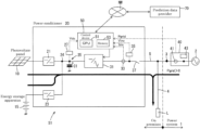
- FIG. 1 is a block diagram of a photovoltaic system S 1 .
- the photovoltaic system S 1 includes a photovoltaic panel 10 , an energy storage apparatus 15 , and a power conditioner 20 .
- the photovoltaic panel 10 is an example of a distributed power supply
- the power conditioner 20 is an example of a power control apparatus.
- the photovoltaic system S 1 is an example of a distributed power generating system.
- the photovoltaic system S 1 is a system not having a dedicated EMS controller.
- the dedicated EMS controller is a dedicated controller for performing EMS control and is a separate apparatus from the power conditioner.
- the dedicated EMS controller is, for example, an apparatus that monitors the state of the distributed power supply system and controls the output of the distributed power supply system on the basis of the supply and demand balance of electricity to adjust the demand for electricity.
- the power conditioner 20 includes a first converter circuit 21 , a second converter circuit 23 , a DC link 25 , a bidirectional inverter circuit 31 , a relay 37 , a control device 50 , a DC voltage detector 27 , an output current detector 33 , and an output voltage detector 35 .
- the photovoltaic panel 10 is connected to the first converter circuit 21 .
- the first converter circuit 21 is a DC/DC converter and boosts and outputs an output voltage (DC) of the photovoltaic panel 10 .
- the first converter circuit 21 may be a chopper.
- the energy storage apparatus 15 is connected to the second converter circuit 23 .
- the energy storage apparatus 15 is, for example, a secondary battery.
- the second converter circuit 23 is a bidirectional DC/DC converter that discharges and charges the energy storage apparatus 15 .
- the second converter circuit 23 may be a bidirectional chopper.
- the photovoltaic panel 10 and the energy storage apparatus 15 are connected in parallel to the DC link 25 via the first converter circuit 21 and the second converter circuit 23 .
- the DC link 25 is located between a connection point 24 of the converter circuits and the bidirectional inverter circuit 31 .
- the DC link 25 is provided with an electrolytic capacitor C 1 .
- the electrolytic capacitor C 1 is provided to stabilize a voltage Vdc of the DC link 25 .
- the DC voltage detector 27 detects the voltage Vdc of the DC link 25 .
- the voltage Vdc of the DC link 25 detected by the DC voltage detector 27 is input to the control device 50 .
- the bidirectional inverter circuit 31 is a bidirectional conversion circuit that selectively performs reverse conversion (inversion) of converting DC to AC and forward conversion (conversion) of converting AC to DC.
- the bidirectional inverter circuit 31 is connected to the DC link 25 , converts DC power input from the DC link 25 to AC power, and outputs the AC power at the time of the reverse conversion operation. Specifically, power corresponding to a voltage increased from a reference value in the DC link 25 by the power generation of the photovoltaic panel 10 is input to the bidirectional inverter circuit 31 . Therefore, the power corresponding to the voltage increased from the reference value is converted from DC to AC and output from the bidirectional inverter circuit 31 .
- the energy storage apparatus 15 can store the surplus power of the photovoltaic panel 10 via the second converter circuit 23 .
- the energy storage apparatus 15 can compensate for the shortage of the power generation amount PG by discharging via the second converter circuit 23 .
- the bidirectional inverter circuit 31 is connected to the power system 1 using a system power supply 2 as an AC power supply via a relay 37 .
- the power system may be of a power company or may be an independent power system achieved by a self-sustained operation output of a large power conditioner.
- the relay 37 is installed for interconnection with the power system 1 . By closing the relay 37 , the photovoltaic system S 1 can be interconnected to the power system 1 .
- the output current detector 33 detects an output current Iinv of the bidirectional inverter circuit 31 .
- the output voltage detector 35 is located on the output side of the bidirectional inverter circuit 31 and detects an output voltage Vinv of the bidirectional inverter circuit 31 .
- the output current Iinv of the bidirectional inverter circuit 31 detected by the output current detector 33 and the output voltage Vinv of the bidirectional inverter circuit 31 detected by the output voltage detector 35 are input to the control device 50 .
- the control device 50 calculates output power (active power) Pinv of the bidirectional inverter circuit 31 on the basis of the output current Iinv and the output voltage Vinv of the bidirectional inverter circuit 31 .
- the output power Pinv is “positive” at the time of reverse conversion and “negative” at the time of forward conversion.
- An on-premise load L as a demand facility is connected to a power line 5 connecting the bidirectional inverter circuit 31 and the power system 1 via a branch line 4 .
- Power can be supplied from both the power conditioner 20 and the power system 1 to the on-premise load L.
- a power reception point 3 is a power supply point by the power system 1 and is located in the vicinity of the boundary between the power system 1 and the premises provided with the on-premise load L that is a demand facility, as illustrated in FIG. 1 .
- the power reception point 3 (power reception line) is located between a point at which the on-premise load L or the branch line 4 is connected to the power line 5 and the system power supply 2 .
- the power system 1 is provided with an external measuring instrument 40 , such as an external transducer, as a meter for detecting power at the power reception point 3 .
- an external measuring instrument 40 such as an external transducer, as a meter for detecting power at the power reception point 3 .
- the external measuring instrument 40 includes a received current detector 41 and a system voltage detector 43 .
- the external measuring instrument 40 is installed corresponding to the power reception point 3 , and the received current detector 41 detects the received current Igrid at the power reception point 3 .
- the system voltage detector 43 detects a system voltage Vgrid of the power system 1 .
- the external measuring instrument 40 calculates received power (active power) Pgrid on the basis of the received current Igrid and the system voltage Vgrid.
- the received power Pgrid detected by the external measuring instrument 40 is input to the control device 50 .
- the received power Pgrid can be used to determine the state of power flow (hereinafter simply referred to as flow.).
- the external measuring instrument 40 is a measuring instrument that measures the received power Pgrid at the power reception point 3 .
- a forward flow ( FIG. 1 : a flow of electricity from the power system toward the inside of the premise) is set to “positive”
- a reverse flow ( FIG. 2 : a power flow of electricity from the inside of the premises to the power system) is set to “negative”.
- the control device 50 includes a central processing unit (CPU) 51 and a memory 53 .
- the memory 53 stores a program for predicting power supply and demand and a program for changing a target value of the received power Pgrid at the power reception point 3 .
- the control device 50 can control the switching between the forward conversion operation and the reverse conversion operation by giving a command to the bidirectional inverter circuit 31 and can control the output of the bidirectional inverter circuit 31 , that is, the output power Pinv.
- the output power Pinv can be controlled by adjusting the output current Iinv.
- the control device 50 can control the connection/non-connection of the photovoltaic panel 10 to the DC link 25 by turning on and off the first converter circuit 21 and can control connection/non-connection of the energy storage apparatus 15 to the DC link 25 by turning on and off the second converter circuit 23 .
- the control device 50 can control the switching between the charge and discharge of the energy storage apparatus 15 via the second converter circuit 23 and can control the charge current and the discharge current of the energy storage apparatus 15 via the second converter circuit 23 .
- the control device 50 obtains the prediction data of the power generation amount PG of the photovoltaic panel 10 and stores the prediction data into the memory 53 .
- the prediction data of the power generation amount PG can be obtained from a prediction data provider 70 via the network NW.
- the prediction data provider 70 may be a provider by a supplier of the power conditioner 20 or a provider of the power company.
- the predicted value of the power generation amount PG of the photovoltaic panel 10 can be obtained from a predicted value of a solar radiation amount X. For example, when the predicted value of the solar radiation amount X is X 1 , the power generation amount can be predicted to be PG 1 from the correlation characteristic of X-PG (see FIG. 3 ).
- the predicted value of the solar radiation amount X may be obtained from weather information.
- the control device 50 predicts power consumption PL of the on-premise load L and stores the power consumption PL into the memory 53 .
- the power consumption PL of the on-premise load L can be predicted from past data. For example, the data of the power consumption PL for the next day can be predicted by statistically processing the data of the power consumption PL for several days.
- the power consumption PL of the on-premise load L can be obtained from the received power Pgrid at the power reception point 3 and the output power Pinv of the bidirectional inverter circuit 31 .
- the power consumption PL of the on-premise load L is the sum of the output power Pinv and the received power Pgrid.
- the power consumption PL of the on-premise load L is a difference between the output power Pinv and the received power Pgrid.
- the control device 50 predicts a supply and demand balance of power in units of several hours from the power generation amount prediction of the photovoltaic panel 10 and the power consumption prediction of the on-premise load L and performs the target value control of the received power Pgrid.
- FIG. 4 is a flowchart of the target value control of the received power Pgrid.
- the target value control of the received power Pgrid is performed for a power-generatable period of the photovoltaic panel 10 , that is, a period from sunrise to sunset.
- the control device 50 reads the power generation amount prediction of the photovoltaic panel 10 and the power consumption prediction of the on-premise load L from the memory 53 (S 10 ).
- the control device 50 obtains a supply and demand balance of power from the power generation amount prediction and the power consumption prediction and determines whether the supply and demand balance is in an allowable range (S 20 ). As shown in Formula (3), when an absolute value of a difference PL-PG between the power consumption PL of the on-premise load L and the power generation amount PG of the photovoltaic panel 10 is smaller than an allowable value K, the supply and demand balance of power can be determined to be in the allowable range.
- the control device 50 sets the target value of the received power Pgrid at the power reception point 3 to the first target value (S 30 ).
- a first target value is a positive value, for example, 500 W.
- the control device 50 adjusts the output of the bidirectional inverter circuit 31 (S 50 ).
- the control device 50 performs control such that the received power Pgrid at the power reception point 3 does not fall below the first target value. That is, when the measured value of the received power Pgrid is lower than the first target value (500 W), the output power Pinv of the bidirectional inverter circuit 31 is lowered by reducing the discharge of the energy storage apparatus 15 to prevent the measured value of the received power Pgrid from falling below the first target value. It is thereby possible to prevent the power discharged from the energy storage apparatus 15 from flowing back to the power system 1 .
- control device 50 may convert the power generated by the solar cell panel 10 to AC by the bidirectional inverter circuit 31 and output the AC without performing the adjustment of the output power Pinv based on the first target value.
- the power generation amount PG of the photovoltaic panel 10 is substantially proportional to solar radiation and thus varies depending on the weather.
- the power consumption PL of the on-premise load L also varies depending on the season and the day of the week. Therefore, the demand balance of power may be lost and deviate from the allowable range.
- the control device 50 changes the target value of the received power Pgrid on the basis of the magnitude relationship between the predicted value of the power generation amount PG of the photovoltaic panel 10 and the predicted value of the power consumption PL of the on-premise load L (S 40 ).
- FIG. 5 is a flowchart of target value change processing.
- the target value change processing includes three steps of S 41 , S 43 , and S 45 .
- the control device 50 determines the magnitude relationship between the power generation prediction and the load prediction of the on-premise load.
- the control device 50 sets the target value of the received power Pgrid to a value larger than the predicted value of the power consumption PL of the on-premise load L.
- the bidirectional inverter circuit 31 performs the forward conversion operation. For example, as illustrated in FIG.
- the control device 50 sets the target value of the received power Pgrid to 15 kW.
- 15 kW is a value obtained by adding 10 kW, which is the maximum output of the power conditioner 20 , to 5 kW, which is the predicted value of the power consumption PL.
- the control device 50 adjusts the output power Pinv of the bidirectional inverter circuit 31 such that the measured value of the received power Pgrid matches the changed target value (S 50 ).
- the output power Pinv of the bidirectional inverter circuit 31 is adjusted to ⁇ 10 kW as illustrated in FIG. 6 . That is, the bidirectional inverter circuit 31 performs the forward conversion operation of converting AC power input from the power system 1 to DC power and outputting the DC power to the energy storage apparatus 15 , and the energy storage apparatus 15 can be charged with the power generated by the solar cell panel 10 and the power generated by the distributed power supply outside the premises connected to the power system 1 .
- the distributed power supply outside the premises is a power supply using new energy, such as a solar cell panel, and is not illustrated.
- the target value of the received power Pgrid is maintained at the changed target value.
- the energy storage apparatus 15 is charged with the output of the photovoltaic panel 10 and the maximum output of the power conditioner 20 of 10 kW.
- the target value of the received power Pgrid may be further changed from the changed target value. For example, when the predicted value of the power consumption PL decreases from 5 kW to 1 kW, the target value of the received power Pgrid may be changed from 15 kW to 11 kW.
- 11 kW is a value obtained by adding 10 kW, which is the maximum output of the power conditioner 20 , to 1 kW, which is the predicted value after the increase or decrease of the power consumption PL.
- the power generation amount PG of the photovoltaic panel 10 is larger than the power consumption PL of the on-premise load L, the supply of electricity is excessive, and the frequency of the system voltage of the power system 1 tends to increase.
- the energy storage apparatus 15 is charged and used as an on-premise load, so that the demand for electricity can be increased to prevent an increase in the frequency of the power system 1 .
- the control device 50 sets the target value of the received power Pgrid to a value smaller than the predicted value of the power consumption PL of the on-premise load L.
- the bidirectional inverter circuit 31 performs the reverse conversion operation.
- the target value of the received power Pgrid may be plus (forward flow) or minus (reverse flow) so long as the target value is smaller than the predicted value of the power consumption PL of the on-premise load L. For example, as illustrated in FIG.
- the control device 50 sets the target value of the received power Pgrid to ⁇ 5 kW.
- ⁇ 5 kW is a value obtained by subtracting 10 kW, which is the maximum output of the power conditioner 20 , from 5 kW, which is the predicted value of the power consumption PL.
- the control device 50 adjusts the bidirectional inverter circuit 31 such that the measured value of the received power Pgrid matches the changed target value (S 50 ).
- the output power Pinv of the bidirectional inverter circuit 31 is adjusted to 10 kW by the control device 50 .
- the output power Pinv may be adjusted by adjusting the discharge amount of the energy storage apparatus 15 via the second converter circuit 23 . As shown in FIG.
- the bidirectional inverter circuit 31 performs the reverse conversion operation of converting DC power input from the solar cell panel 10 and the energy storage apparatus 15 to AC and outputting the AC power, and power corresponding to a difference between the output of 10 kW of the power conditioner 20 and the power consumption of 5 kW of the on-premise load L flows reversely from the power conditioner 20 to the power system 1 .
- the target value of the received power Pgrid is maintained at the changed target value.
- the energy storage apparatus 15 is discharged at the maximum output of 10 kW of the power conditioner 20 , and power reversely flows from the power conditioner 20 to the power system 1 .
- the target value of the received power Pgrid may be further changed from the changed target value. For example, when the predicted value of the power consumption PL decreases from 5 kW to 1 kW, the target value of the received power Pgrid may be changed from ⁇ 5 kW to ⁇ 9 kW.
- ⁇ 9 kW is a value obtained by subtracting 10 kW, which is the maximum output of the power conditioner 20 , from 1 kW, which is the predicted value after the increase or decrease of the power consumption PL.
- the power consumption PL of the on-premise load L is larger than the power generation amount PG of the photovoltaic panel 10 , the demand for electricity is excessive, and the frequency of the system voltage of the power system 1 tends to decrease.
- the energy storage apparatus 15 charged so far with the surplus power of the photovoltaic panel 10 is discharged and used as a power supply, so that the supply of electricity can be increased to prevent a decrease in the frequency of the power system 1 .
- the power conditioner 20 predicts the supply and demand balance of electricity and performs demand adjustment (demand response) of electricity. It is thereby possible to realize the EMS technology without using a dedicated EMS controller.
- the present technique is suitable for realizing a relatively small-scale smart city in land, such as a remote island, where the introduction of a distributed power supply system is desired due to high transportation cost of fossil fuel, effective use of renewable energy, or the like.
- land such as a remote island
- FIG. 8 is a block diagram of a photovoltaic system S 2 .
- the photovoltaic system S 2 includes three power conditioners 20 A, 20 B, 20 C.
- the three power conditioners 20 A, 20 B, 20 C are connected to a power line 5 via branch lines 5 A, 5 B, 5 C.
- Three power conditioners 20 A, 20 B, 20 C are connected in parallel to a power system 1 .
- the power conditioner 20 A includes a control device 50 A.
- a photovoltaic panel 10 A and an energy storage apparatus 15 A are connected in parallel to a power conditioner 20 A.
- the power conditioner 20 B includes a control device 50 B.
- a photovoltaic panel 10 B and an energy storage apparatus 15 B are connected in parallel to a power conditioner 20 B.
- the power conditioner 20 B is connected to the power conditioner 20 A via a communication line R 1 and can communicate with the power conditioner 20 A.
- the power conditioner 20 C includes a control device 50 C.
- a photovoltaic panel 10 C and an energy storage apparatus 15 C are connected in parallel to a power conditioner 20 C.
- the power conditioner 20 C is connected to the power conditioner 20 B via a communication line R 2 and can communicate with the power conditioner 20 A via the power conditioner 20 B.
- Power conditioner 20 A has a control function different from those of the power conditioners 20 B and the power conditioner 20 C, and the power conditioner 20 A is a master device that integrally controls the output power of the three power conditioners 20 A, 20 B, 20 C.
- the power conditioner 20 B and the power conditioner 20 C are slave devices that adjust output power in accordance with a command from power conditioner 20 A.
- a first on-premise load Lo, a second on-premise load La, a third on-premise load Lb, and a fourth on-premise load Lc are provided in the premises.
- the first on-premise load Lo is connected to the power line 5 .
- the second on-premise load La, the third on-premise load Lb, and the fourth on-premise load Lc are connected to the branch lines 5 A, 5 B, 5 C, respectively.
- the power system 1 is provided with an external measuring instrument 40 as a meter for detecting power at a power reception point 3 .
- the external measuring instrument 40 includes a received current detector 41 and a system voltage detector 43 .
- the received current detector 41 detects a received current Igrid at the power reception point 3 .
- the system voltage detector 43 detects a system voltage Vgrid of the power system 1 .
- the external measuring instrument 40 calculates received power (active power) Pgrid on the basis of the received current Igrid and the system voltage Vgrid.
- a received power Pgrid detected by the external measuring instrument 40 is input to the control device 50 A of the power conditioner 20 A.
- the power conditioner 20 A obtains a supply and demand balance of electricity from the power generation prediction of the photovoltaic panels 10 A, 10 B, 10 C and the load prediction of the on-premise loads Lo, La, Lb, Lc and calculates a target value of the received power Pgrid at the power reception point 3 in accordance with the supply and demand balance of electricity.
- the power conditioner 20 A integrally controls the output power of the three power conditioners 20 A, 20 B, 20 C connected in parallel such that the received power Pgrid at the power reception point 3 matches the target value. That is, when the received power Pgrid at the power reception point 3 does not match the target value, the power conditioner 20 A determines the shares of the adjustment amount and sends a command to each of the power conditioner 20 B and the power conditioner 20 C. Then, by adjusting the output power by each of the power conditioners 20 A, 20 B, 20 C, the received power Pgrid at the power reception point 3 can be caused to follow the target value.
- the power conditioner 20 A transmits a command to each of the power conditioner 20 B and the power conditioner 20 C to increase the output power of each of the three power conditioners 20 A to 20 C from the current value by “Y/3”.
- the total output power of the power conditioners 20 A, 20 B, 20 C increases by “Y”.
- the received power Pgrid at the power reception point 3 can be decreased by “Y” to be matched with the target value.
- the sharing ratio of the power conditioners 20 A, 20 B, 20 C may be determined in accordance with the state of charge (SOC) of the energy storage apparatus 15 .
- the output power of each of the power conditioner 20 A and the power conditioner 20 B may be set to “ ⁇ Y/2”, and only the two energy storage apparatuses 15 A, 15 B with low SOC may be charged. In this way, the two energy storage apparatuses 15 A, 15 B each having a low SOC are charged, so that the difference in SOC among the energy storage apparatuses 15 A, 15 B, 15 C can be prevented, and the three energy storage apparatuses 15 A, 15 B, 15 C can be used uniformly. This is effective to the long life of the photovoltaic system S 2 .
- FIG. 10 is a comparative example of the photovoltaic system.
- a system S 3 in FIG. 10 includes three power conditioners 120 A, 120 B, 120 C connected in parallel.
- the three power conditioners 120 A, 120 B, 120 C are branched and connected to the power line 5 via the branch lines 5 A, 5 B, 5 C, and are connected in parallel.
- the branch lines 5 A, 5 B, 5 C are provided with power meters 130 A, 130 B, 130 C, respectively.
- the power meters 130 A, 130 B, 130 C measure received power at on-premise load points 6 A, 6 B, 6 C.
- a control unit 150 A of the power conditioner 120 A monitors the measured value of the power meter 130 A and controls the output power such that the received power at the on-premise load point 6 A becomes a target value.
- a control unit 150 B of the power conditioner 120 B monitors the measured value of the power meter 130 B and controls the output power such that the received power at the on-premise load point 6 B becomes a target value.
- a control unit 150 C of the power conditioner 120 C monitors the measured value of the power meter 130 C and controls the output power such that the received power at the on-premise load point 6 C becomes a target value.
- the received power Pgrid at the power reception point 3 is a sum of the received power at the on-premise load point 6 A, the received power at the on-premise load point 6 B, and the received power at the on-premise load point 6 C.
- the power conditioners 120 A, 120 B, 120 C independently control the output such that the received power at each of the on-premise load points 6 A, 6 B, 6 C becomes the target value, whereby the received power Pgrid at the power reception point 3 can be controlled to the target value.
- the power conditioners 120 A, 120 B, 120 C independently control the output, there is a concern that the output adjustment performed by a certain power conditioner affects the output of another power conditioner, and as a result, the hunting of the command value occurs to make the power flow at the power reception point 3 unstable.
- the power conditioner 20 A integrally controls the output power of each of the three power conditioners 20 A, 20 B, 20 C. Hence the hunting of the command value can be prevented to stabilize the power flow at the power reception point 3 .
- the distributed power supply has been the photovoltaic panel 10 .
- the distributed power supply is a generic term for all small-scale power generation facilities dispersedly disposed adjacent to the demand site and may be, for example, a wind power generator or a biomass power generator in addition to the photovoltaic panel 10 .
- the output of the power generator may be rectified by a rectifier to be converted to a DC, and the power generator is then connected to the DC link 25 via a converter circuit.
- the energy storage apparatus 15 in the case of excessive supply of electricity ( FIG. 6 ), the energy storage apparatus 15 has been charged to increase the demand for electricity. In the case of excessive demand for electricity ( FIG. 7 ), the energy storage apparatus 15 has been discharged to increase the amount of electricity supplied. Only one of these adjustments may be performed. That is, only adjustment to increase the demand for electricity may be performed in the case of excessive supply of electricity, or only adjustment to increase the supply of electricity may be performed in the case of excessive demand for electricity.
- the adjustment of the supply amount of electricity is not limited to the adjustment of the discharge amount of the energy storage apparatus 15 but may be performed using the power factor of the bidirectional inverter circuit 31 .
- the energy storage apparatus 15 in the case of excessive supply of electricity (in the case of FIG. 6 ), the energy storage apparatus 15 has been charged with the power generated by the solar cell panel 10 and the power from the distributed power supply outside the premises connected to the power system 1 .
- the energy storage apparatus 15 may be charged only with the power generated by the solar cell panel 10 or may be charged only with the power from the distributed power supply outside the premises connected to the power system 1 .
- the bidirectional inverter circuit 31 may be stopped, or the relay 37 may be opened to disconnect the power conditioner 20 from the power system 1 .
- the target value of the received power Pgrid may be made equal to the power consumption PL of the on-premise load L, and power may be supplied from the power system 1 to the on-premise load L.
- the conversion circuit has been the bidirectional inverter circuit 31 .
- the conversion circuit only may only perform reverse conversion of converting power supplied from the distributed power supply from DC to AC and outputting the converted power and may not be bidirectional.
- the distributed power supply may not necessarily include the energy storage apparatus 15 .
- the control device 50 has obtained the prediction data of the power generation amount PG from the prediction data provider 70 via the network NW.
- the power generation amount PG may be predicted by the control device 50 .
- the control device 50 has adjusted the supply and demand for electricity when the supply and demand balance of power is out of the allowable range. Specifically, in the case of PG>PL, the control (S 43 ) has been performed to increase the demand for electricity by making the target value of the received power Pgrid larger than the predicted value of the power consumption PL of the on-premise load L. In the case of PL>PG, the control (S 45 ) has been performed to increase the supply of electricity by making the target value of the received power Pgrid smaller than the predicted value of the power consumption PL of the on-premise load L.
- the control to increase the demand for electricity may be performed at any time so long as the condition of PG>PL is satisfied, or may be performed when the supply and demand balance of power is in the allowable range.
- the control to increase the supply of electricity may be performed at any time so long as the condition of PL>PG is satisfied, or may be performed when the supply and demand balance of power is in the allowable range. It is sufficient when the demand for electricity increases (the supply of electricity decreases) in the case of PG>PL and the supply of electricity increases (the demand for electricity decreases) in the case of PL>PG, and the target values of the received power Pgrid may be Pgrid1>0 and Pgrid2 ⁇ 0.
- Pgrid1 is a target value of the received power Pgrid in the case of PG>PL
- Pgrid2 is a target value of the received power Pgrid in the case of PL>PG. Further, a condition of Pgrid1>Pgrid2 may be satisfied.
- the energy storage apparatus 15 in the case of excessive demand for electricity (in the case of FIG. 7 ), the energy storage apparatus 15 has been discharged in order to set Pgrid2 to ⁇ 5 kW.
- the received power can be controlled to Pgrid2 without discharging the energy storage apparatus 15 (e.g., when Pgrid2>0), the energy storage apparatus 15 may not be discharged.
Landscapes
- Engineering & Computer Science (AREA)
- Power Engineering (AREA)
- Supply And Distribution Of Alternating Current (AREA)
- Charge And Discharge Circuits For Batteries Or The Like (AREA)
Abstract
Description
PL=Pinv+Pgrid (1)
PL=Pinv−Pgrid (2)
|PL−PG|<K (3)
-
- 1: power system
- 2: system power supply
- 3: power reception point
- 10: photovoltaic panel (example of “distributed power supply” of
- present invention)
- 15: energy storage apparatus
- 20: Power conditioner (example of “power control apparatus” of
- present invention)
- 21: first converter circuit
- 23: second converter circuit
- 31: inverter circuit
- 40: external measuring instrument
- 50: control device
- 120A: master device
- 120B: slave device
- 120C: slave device
Claims (20)
Applications Claiming Priority (3)
| Application Number | Priority Date | Filing Date | Title |
|---|---|---|---|
| JP2019-085131 | 2019-04-26 | ||
| JP2019085131 | 2019-04-26 | ||
| PCT/JP2020/016875 WO2020218191A1 (en) | 2019-04-26 | 2020-04-17 | Power control device, method of controlling power control device, and distributed power generation system |
Publications (2)
| Publication Number | Publication Date |
|---|---|
| US20220200287A1 US20220200287A1 (en) | 2022-06-23 |
| US11929621B2 true US11929621B2 (en) | 2024-03-12 |
Family
ID=72942704
Family Applications (1)
| Application Number | Title | Priority Date | Filing Date |
|---|---|---|---|
| US17/603,261 Active 2040-11-14 US11929621B2 (en) | 2019-04-26 | 2020-04-17 | Power control apparatus, control method for power control apparatus, and distributed power generating system |
Country Status (4)
| Country | Link |
|---|---|
| US (1) | US11929621B2 (en) |
| JP (1) | JP7589680B2 (en) |
| CN (1) | CN113767537A (en) |
| WO (1) | WO2020218191A1 (en) |
Families Citing this family (3)
| Publication number | Priority date | Publication date | Assignee | Title |
|---|---|---|---|---|
| JP7404751B2 (en) * | 2019-10-08 | 2023-12-26 | 株式会社Gsユアサ | Energy management device, energy management method |
| US11522366B1 (en) * | 2021-07-20 | 2022-12-06 | Lunar Energy, Inc. | Photovoltaic disconnect |
| US20250125622A1 (en) * | 2022-03-07 | 2025-04-17 | Musashi Seimitsu Industry Co., Ltd. | Power control system |
Citations (11)
| Publication number | Priority date | Publication date | Assignee | Title |
|---|---|---|---|---|
| JP4765162B2 (en) | 2000-12-04 | 2011-09-07 | 株式会社Gsユアサ | Power storage type solar power generation system |
| JP2012100504A (en) | 2010-11-05 | 2012-05-24 | Creative Techno Solution Co Ltd | Power supply system |
| JP2012222908A (en) | 2011-04-06 | 2012-11-12 | Kyocera Corp | Power conditioner, power control system, and power control method |
| US20130088900A1 (en) * | 2011-10-10 | 2013-04-11 | Jong-Ho Park | Energy storage system and controlling method of the same |
| WO2014141499A1 (en) | 2013-03-14 | 2014-09-18 | オムロン株式会社 | Power control device, power control method, program, and power control system |
| JP2017017792A (en) | 2015-06-29 | 2017-01-19 | 新電元工業株式会社 | Distribution type power supply device |
| JP2017134494A (en) | 2016-01-26 | 2017-08-03 | 三菱電機株式会社 | Determination device, determination system, determination method, and program |
| US9935465B2 (en) * | 2014-01-20 | 2018-04-03 | Mitsubishi Electric Corporation | Power conversion device |
| JP2018166379A (en) | 2017-03-28 | 2018-10-25 | 大阪瓦斯株式会社 | Distributed power supply system |
| JP2018182847A (en) | 2017-04-07 | 2018-11-15 | 株式会社ダイヘン | Grid-connected system and power system |
| US20190181644A1 (en) * | 2016-09-13 | 2019-06-13 | Korea Electric Power Corporation | Pcs efficiency-considered microgrid operation device and operation method |
-
2020
- 2020-04-17 US US17/603,261 patent/US11929621B2/en active Active
- 2020-04-17 CN CN202080031096.1A patent/CN113767537A/en active Pending
- 2020-04-17 WO PCT/JP2020/016875 patent/WO2020218191A1/en not_active Ceased
- 2020-04-17 JP JP2021516074A patent/JP7589680B2/en active Active
Patent Citations (12)
| Publication number | Priority date | Publication date | Assignee | Title |
|---|---|---|---|---|
| JP4765162B2 (en) | 2000-12-04 | 2011-09-07 | 株式会社Gsユアサ | Power storage type solar power generation system |
| JP2012100504A (en) | 2010-11-05 | 2012-05-24 | Creative Techno Solution Co Ltd | Power supply system |
| JP2012222908A (en) | 2011-04-06 | 2012-11-12 | Kyocera Corp | Power conditioner, power control system, and power control method |
| US20130088900A1 (en) * | 2011-10-10 | 2013-04-11 | Jong-Ho Park | Energy storage system and controlling method of the same |
| WO2014141499A1 (en) | 2013-03-14 | 2014-09-18 | オムロン株式会社 | Power control device, power control method, program, and power control system |
| JP2014180130A (en) | 2013-03-14 | 2014-09-25 | Omron Corp | Power controller, power control method, program, and power control system |
| US9935465B2 (en) * | 2014-01-20 | 2018-04-03 | Mitsubishi Electric Corporation | Power conversion device |
| JP2017017792A (en) | 2015-06-29 | 2017-01-19 | 新電元工業株式会社 | Distribution type power supply device |
| JP2017134494A (en) | 2016-01-26 | 2017-08-03 | 三菱電機株式会社 | Determination device, determination system, determination method, and program |
| US20190181644A1 (en) * | 2016-09-13 | 2019-06-13 | Korea Electric Power Corporation | Pcs efficiency-considered microgrid operation device and operation method |
| JP2018166379A (en) | 2017-03-28 | 2018-10-25 | 大阪瓦斯株式会社 | Distributed power supply system |
| JP2018182847A (en) | 2017-04-07 | 2018-11-15 | 株式会社ダイヘン | Grid-connected system and power system |
Non-Patent Citations (1)
| Title |
|---|
| International Search Report (ISR) (PCT Form PCT/ISA/210), in PCT/JP2020/016875, dated Jun. 23, 2020. |
Also Published As
| Publication number | Publication date |
|---|---|
| JP7589680B2 (en) | 2024-11-26 |
| JPWO2020218191A1 (en) | 2020-10-29 |
| CN113767537A (en) | 2021-12-07 |
| US20220200287A1 (en) | 2022-06-23 |
| WO2020218191A1 (en) | 2020-10-29 |
Similar Documents
| Publication | Publication Date | Title |
|---|---|---|
| US10923919B2 (en) | Method and apparatus for controlling power flow in a hybrid power system | |
| US11233398B2 (en) | Distributed power supply system | |
| US8982590B2 (en) | Solar generation method and system | |
| EP4246751B1 (en) | Method of controlling of battery energy storage system of power system with high dynamic loads | |
| US11929621B2 (en) | Power control apparatus, control method for power control apparatus, and distributed power generating system | |
| KR101644522B1 (en) | Power supply system of ac microgrid three phase | |
| US20210075216A1 (en) | Renewable energy power generation and storage control device for reverse flow prevention type self-consumption | |
| JP6828567B2 (en) | Grid interconnection system and power system | |
| CN104836247A (en) | Optical storage micro grid system for realizing energy storage capacity dynamic optimization | |
| JP5373528B2 (en) | Power distribution equipment | |
| US11205911B2 (en) | Energy storage system | |
| JP2023073396A (en) | power supply system | |
| CN108258678A (en) | A kind of solar energy system and its method for supplying electricity to multi-load unit | |
| US20210344198A1 (en) | Reactive Power Control Method for an Integrated Wind and Solar Power System | |
| JP2020184851A (en) | Dc power network and control system of dc power network | |
| Vieira Filho et al. | Exploring the impact of passive direct current microgrids on off-grid energy transition: Concept development, testing, and implementation in a remote amazonian community | |
| JP7529200B2 (en) | Energy storage system, expansion function unit with storage battery, and expansion function unit | |
| JP7529199B2 (en) | Energy storage system, expansion function unit with storage battery, and expansion function unit | |
| Abdullah et al. | Performance and reliability investigation of practical microgrid with photovoltaic units | |
| EP3619783B1 (en) | Power conversion system and method | |
| CN120188363A (en) | Inverter system and method for operating the same |
Legal Events
| Date | Code | Title | Description |
|---|---|---|---|
| FEPP | Fee payment procedure |
Free format text: ENTITY STATUS SET TO UNDISCOUNTED (ORIGINAL EVENT CODE: BIG.); ENTITY STATUS OF PATENT OWNER: LARGE ENTITY |
|
| AS | Assignment |
Owner name: GS YUASA INTERNATIONAL LTD., JAPAN Free format text: ASSIGNMENT OF ASSIGNORS INTEREST;ASSIGNORS:ENDO, HIROAKI;YOKOYAMA, MASAO;HONGO, SHINICHI;REEL/FRAME:057778/0341 Effective date: 20211012 |
|
| STPP | Information on status: patent application and granting procedure in general |
Free format text: DOCKETED NEW CASE - READY FOR EXAMINATION |
|
| STPP | Information on status: patent application and granting procedure in general |
Free format text: NON FINAL ACTION MAILED |
|
| STPP | Information on status: patent application and granting procedure in general |
Free format text: RESPONSE TO NON-FINAL OFFICE ACTION ENTERED AND FORWARDED TO EXAMINER |
|
| STPP | Information on status: patent application and granting procedure in general |
Free format text: NOTICE OF ALLOWANCE MAILED -- APPLICATION RECEIVED IN OFFICE OF PUBLICATIONS |
|
| STPP | Information on status: patent application and granting procedure in general |
Free format text: PUBLICATIONS -- ISSUE FEE PAYMENT RECEIVED |
|
| STPP | Information on status: patent application and granting procedure in general |
Free format text: PUBLICATIONS -- ISSUE FEE PAYMENT VERIFIED |
|
| STCF | Information on status: patent grant |
Free format text: PATENTED CASE |