CROSS REFERENCE TO RELATED APPLICATIONS
This application is a U.S. national stage of International Patent Application No. PCT/JP2020/020551 filed on May 25, 2020 and is based on Japanese Patent Application No. 2019-189454 filed on Oct. 16, 2019 the disclosures of which are incorporated herein by reference.
TECHNICAL FIELD
The present invention relates to a brake device for a caster.
BACKGROUND ART
As disclosed in PTL 1, a brake device for a caster is available, in which a brake shoe is disposed at a frame (fork), and an operation body is inserted and fitted in a hole drilled in the top panel of a frame, and the operation body is operated synchronously via a transfer means constituted of a cam, a link rod, and the like connected to a brake operation lever.
CITATION LIST
Patent Literature
[PTL 1] Japanese Patent Application Publication No. 2008-302903
SUMMARY OF INVENTION
Technical Problem
Incidentally, in the brake device disclosed in PTL 1, the brake shoe is brought into contact with the circumferential surface of a roller so that the roller is braked by frictional resistance caused by the contact. For this reason, the braking effect may be reduced, and the circumferential surface of the roller may be damaged.
The present invention was completed in view of the problem in the background art. It is an object of the present invention to provide a break device for a caster, which has a simple structure, provides reliable braking, has no risk of damaging the circumferential surface of a roller, and has high durability.
Solution to Problem
In order to attain the foregoing object, the present invention provides a brake device for a caster according to [1] to [5] below.
[1] A brake device for a caster including: a plurality of projecting parts formed concentrically on opposite side-surfaces of a roller, and levers set across the roller at opposite side-panels of a fork so as to be opposed to each of the projecting parts, and a claw formed at a tip of each of the levers so as to be opposed to the projecting parts, wherein the levers are operated, so that the claw is engaged with a concave part formed between the projecting parts, thereby locking rotation of the roller.
[2] The brake device for a caster according to the [1], wherein an inclined surface inclined at an acute angle with respect to a line connecting an outer circumferential end of the projecting part and a center of the roller is formed at an end face of the projecting part that comes in contact with the claw of the lever.
[3] The brake device for a caster according to the [1] or [2], wherein the lever is operated by a cable coupled to an operation lever, and the cable is rotatably coupled to the lever.
[4] The brake device for a caster according to the [3], wherein a spring is interposed at an intermediate point of the cable and/or between the cable and the lever.
[5] The break device for a caster according to the [3] or [4], wherein a cable coupling unit having a slide body is set at an intermediate point of the cable, and the cable on the operation lever side and a cable on the lever side are coupled via the slide body.
Advantageous Effects of Invention
With the break device for a caster in accordance with the present invention according to the [1], the claw of the lever is engaged with the projecting part formed at the side-surface of the roller, thereby applying brake to the roller. Accordingly, a reliable braking effect can be obtained, and the circumferential surface of the roller will not be damaged. For this reason, the durability is also high, and further the structure is simple.
With the break device for a caster in accordance with the present invention according to the [2], in addition to the effect, the claw of the lever is engaged with the inclined surface of the projecting part, and hence the engagement becomes firm, resulting in further enhancement of the braking effect.
With the break device for a caster in accordance with the present invention according to the [3], in addition to the effect, even when the roller rotates, the cable will not be twisted.
With the break device for a caster in accordance with the present invention according to the [4], in addition to the effect, when release cannot be performed with ease due to biting of the claw of the lever into the concave part between the projecting parts, or the like, the interposed spring is stretched, which can reduce the burden on the cable. In addition, also subsequently, the spring is urged on the lever in the direction of release, which performs the action of releasing the brake.
With the break device for a caster in accordance with the present invention according to the [5], in addition to the effect, a plurality of the cables of the operation levers are coupled with the slide body, and a plurality of cables to the levers of the casters are coupled with the slide body. As a result, it is possible to transfer the power of the selected operation lever to each caster.
BRIEF DESCRIPTION OF DRAWINGS
FIG. 1 is a perspective view showing one embodiment of a trolley mounting a break device for a caster in accordance with the present invention thereon.
FIG. 2 is a conceptual longitudinal cross sectional view of a caster showing the essential part of the break device for a caster in accordance with the present invention, and shows a brake operating state.
FIG. 3 is a conceptual partial perspective view of a caster showing the essential part of the break device for a caster in accordance with the present invention, and shows a brake release state.
FIG. 4 is a conceptual cross sectional view showing an operation part of the break device for a caster in accordance with the present invention.
FIG. 5 is a conceptual cross sectional view showing a cable coupling unit of the break device for a caster in accordance with the present invention.
FIG. 6 is a conceptual longitudinal cross sectional view of a caster showing the essential part of the break device for a caster in accordance with the present invention, and shows a brake release state.
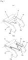
FIG. 7 is a conceptual perspective view showing a modified example of a lever of the break device for a caster in accordance with the present invention.
FIG. 8 is a conceptual longitudinal cross sectional view of a caster showing a modified example of the essential part of the break device for a caster in accordance with the present invention, and (a) is a view showing a brake operation state, and (b) is a view showing a break release state.
FIG. 9 is a conceptual cross sectional view showing a modified example of a cable coupling unit of the break device for a caster in accordance with the present invention.
DESCRIPTION OF EMBODIMENTS
Below, a break device for a caster in accordance with the present invention will be described in details by way of embodiments shown in the accompanying drawings.
FIG. 1 shows a basket trolley 1. The basket trolley 1 has a rectangular bottom panel 2. Then, a fence 3 is vertically arranged in the periphery of the bottom panel 2. One side of the fence 3 includes double doors 3 a.
Casters 4 are set at the four corners of the bottom panel 2. Out of these, two casters are rotatable casters 4 a, and the residual two casters are fixed casters 4 b. As shown in FIG. 2 , each rotatable caster 4 a includes a fork 5 in a generally U shape including a top panel 5 a and side-panels 5 b bent in a direction at right angles from the opposite ends thereof. A shaft 6 is laid across both the side-panels 5 b, 5 b of the fork 5 in an inserted manner, and a roller 7 is rotatably held by the shaft 6. At the lower surface of the bottom panel 2 of the basket trolley 1, a mount stand 8 is fixedly set as shown in FIG. 2 . The top panel 5 a of the fork 5 is rotatably set at the mount stand 8 via a bearing not shown.
The basket trolley 1 includes a brake device 10 of the rotatable caster 4 a set therein. As shown in FIG. 1 , the brake device 10 includes a brake part 11 set at the rotatable caster 4 a, an operation part 12 set at a column 3 b situated diagonally with respect to the fence 3 in the embodiment shown, and a power transfer means 13 for coupling the brake part 11 and the operation part 12.
The brake part 11 includes a frame 14. The frame 14 includes a tubular coupling tube 15, and levers 16 projecting in a direction at right angles from the opposite ends thereof in the embodiment illustrated in FIG. 3 . Each lever 16 includes a claw 16 a at the tip thereof. Then, the frame 14 is rotatably held by fitting the tubular coupling tube 15 to a shaft 5 c set across the side-panels 5 b, 5 b of the fork 5. Then, the frame 14 is arranged so that the levers 16 sandwich the roller 7 as shown in FIG. 3 . Further, a rod 17 for hanging a spring (or a direct cable) described later thereon is set across both the levers 16.
Whereas, at the brake part 11, a plurality of projecting parts 19 are formed at disks (the opposite side-panels of the wheel) 18 on the opposite side-surfaces of the roller 7. The projecting parts 19 are arranged at regular intervals in the circumferential direction concentrically with the disk 18. Then, an inclined surface 19 a making an acute angle with the outer circumferential surface is formed at the end of each projecting part 19.
At the operation part 12, a bracket 20 is set at the column 3 b of the fence 3 as shown in FIG. 4 . An operation lever 21 is rotatably set at the bracket 20. A tongue piece 21 a for holding a cable described later is protrusively provided at the base of the operation lever 21.
The power transfer means 13 includes a cable coupling unit 22 set at the side surface of the fence 3. The cable coupling unit 22 includes a slide body 24 in a case 23 in the embodiment shown in FIG. 5 . The slide body 24 is for coupling an operation part side cable 25 and a brake part side cable 26. With the cable coupling unit 22, an outer tube 25 a of the cable 25 is engaged with one end of the case 23, and an outer tube 26 a of the cable 26 is engaged with the other end of the case 23. Then, an inner cable 25 b of the cable 25 is engaged with one end of the slide body 24 by a screw 27, and an inner cable 26 b of the cable 26 is engaged with the other end of the slide body 24 via a spring 28.
Further, with the cable coupling unit 22, the slide body 24 is urged to the brake part side (downward of FIG. 5 ) by a spring 29 fitted loosely to the inner cable 25 b of the cable 25. Incidentally, as shown in FIG. 1 , the cable 25 is guided upward from the operation part 12 along the column 3 b, and crawls on the upper end and the side surface of the fence 3 to be guided to the cable coupling unit 22. Whereas, the cable 26 crawls on the side surface of the fence 3 to be guided to the caster 4 a, and is guided to the fork 5 through the rotation axis of the mount stand 8 as shown in FIG. 2 . The outer tube 26 a of the cable 26 is engaged with the top panel 5 a, and the inner cable 26 b is rotatably coupled to the end of a spring 30 using a swivel mechanism. Then, the other end of the spring 30 is engaged with the rod 17 of the lever 16.
Incidentally, when the spring 28 is provided at the cable coupling unit 22, the spring 30 provided at the brake part 11 is not necessarily required. It may be configured such that the inner cable 26 b of the cable 26 is directly coupled to the rod 17 of the lever 16. Conversely, when the spring 30 is provided at the brake part 11, for the cable coupling unit 22, it may be configured such that the inner cable 26 b of the cable 26 is directly engaged with the other end of the slide body 24 without the spring 28 interposed therebetween.
The opposite side end of the cable 25 is engaged with the tongue piece 21 a of the operation lever 21 at the operation part 12 as shown in FIG. 4 .
With the brake device 10 of the rotatable caster 4 a of the embodiment, in the normal state, namely, at the position at which the operation lever 21 is not operated as indicated with a solid line, the slide body 24 of the cable coupling unit 22 is moved toward the brake part (downward of FIG. 5 ) by the urging force of the spring 29. As a result, the inner cable 26 b of the cable 26 is relaxed as shown in FIG. 2 , so that the lever 16 moves downward by its own weight, and further, the spring 28 or 30 presses thereagainst (in this case, the spring 28 or 30 performs an action of a press spring). Accordingly, the lever 16 is held downward, so that the claw 16 a of the lever 16 is fitted into the concave part 19 b between the projecting parts 19. In this state, the roller 7 is locked against the rotation in the forward direction (also in the backward direction) of the trolley 1. On the other hand, for the rotation in the counterclockwise direction of the roller 7, the tip wall 16 b of the lever 16 comes in touch with the end face 19 c of the adjacent projecting part 19, thereby hindering the rotation.
When the operation lever 21 is operated in the direction of the column 3 b (the direction indicated with a two-dot chain line of FIG. 4 ), the inner cable 25 b of the cable 25 is lowered. As a result, the slide body 24 of the cable coupling unit 22 is pulled in the direction of the operation part (upward of FIG. 5 ) against the urging force of the spring 29. Then, the lever 16 is rotated upward in FIG. 2 via the inner cable 26 b of the cable 26 connected to the slide body 24. Accordingly, the claw 16 a is separated from the projecting part 19 provided in addition on the roller 7. Therefore, the rotation of the roller 7 becomes free, and the trolley 1 can be run in the desirable direction.
At this step, namely, in order to separate the claw 16 a of the lever 16 from the projecting part 19, it is necessary to rotate the roller 7 slightly anti-rotationally (in the counterclockwise direction in FIG. 2 ). Meanwhile, the lifting force of the cable 26 acts on the lever 16. The spring 28 interposed at an intermediate point of the cable, or the spring 30 interposed between the cable and the lever is stretched. As a result, the burden on the cable or the damage of the lever can be prevented. In addition, the stretched spring 28 or 30 also subsequently urges the lever 16 in the release direction (in this case, the spring 28 or 30 performs the action of a stretching spring), and performs the action of releasing the brake.
Incidentally, with the break device for the embodiment, the inclined surface 19 a is formed at the projecting part 19, and the claw 16 a of the lever 16 is caused to bite into the inclined surface 19 a. Accordingly, the claw 16 a is engaged with the projecting part 19 with reliability. When the angle of the inclined surface 19 a, namely, the angle made between the line connecting the outer circumferential end of the projecting part 19 and the center of the roller 7 and the inclined surface is large, the engagement between the claw 16 a of the lever 16 and the projecting part 19 becomes more firm. However, when the locking of the roller 7 is released, it becomes difficult to separate the claw 16 a from the projecting part 19. Therefore, in view of these, the angle is preferably about 30 to 50 degrees.
Further, in the embodiment, as shown in FIG. 2 , the end of the inner cable 26 b and the lever 16 are coupled via the stretching spring 30. However, the following is also acceptable. As shown in FIG. 7(a), a T-shaped flat spring 31 is disposed by being laid across the levers 16. A hole 32 is formed at the tip 31 a, and one end of the inner cable 26 b is rotatably coupled to the hole using a swivel mechanism or the like. The following is also acceptable. As shown in FIG. 7(b), a torsion coil spring 33 is disposed by being laid across the levers 16, and a hole 33 a is formed at the center of the torsion coil spring 33. One end of the inner cable 26 b is rotatably coupled with the hole 33 a using a swivel mechanism, or the like.
Further, in the embodiment, it is configured such that the lever 16 is engaged with the projecting part 19 projecting toward the side of the roller 7 from above as shown in FIG. 3 . However, the following configuration is also acceptable. As shown in FIG. 8 , the projecting part 19 is formed at the inner circumferential surface of the wheel 34 of the roller 7 in such a manner as to project in the direction of the shaft 6, so that the lever 16 is engaged with the projecting part 19 from below. Incidentally, the members and the parts performing the same actions as those in the embodiment are given the same reference numerals and signs in FIG. 8 , and the description thereon is omitted.
Further, in the embodiment, as shown in FIG. 5 , the configuration of the cable coupling unit 22 is configured such that the inner cable 26 b of the brake part side cable 26 is engaged with the other end of the slide body 24 via the spring 28. However, when the spring 30 is provided at the brake part 11, as shown in FIG. 9 , for the cable coupling unit 22, it may be configured such that the inner cable 26 b of the cable 26 is directly engaged, by a screw 35, with the other end of the slide body 24 without the spring 28 interposed therebetween.
Up to this point, a description has been given to the embodiments of the break device for the rotatable caster in accordance with the present invention. However, it is naturally understood that the present invention is not limited to the embodiments at all, and may be variously modified or changed within the scope of the technical idea of the present invention described in the appended claims.
For example, in the embodiment, a description has been given by taking the basket trolley 1 as an example. However, the break device for a caster in accordance with the present invention is widely applicable as a break device for a caster for use in, for example, in addition to a flat trolley except for a basket trolley, and a folding trolley, a wheelchair, a stretcher, a baby buggy, a wagon, a bed, a copying machine, an IV stand, a compressor, a spot cooler, a power generator, or a welding machine.
REFERENCE SIGNS LIST
- 1 Trolley
- 2 Bottom panel
- 3 Fence
- 3 a Door
- 3 b Column
- 4 Caster
- 4 a Rotatable caster
- 4 b Fixed caster
- 5 Fork
- 5 a Top panel
- 5 b Side-panel
- 5 c Shaft
- 6 Shaft
- 7 Roller
- 8 Mount stand
- 10 Brake device
- 11 Brake part
- 12 Operation part
- 13 Power transfer means
- 14 Frame
- 15 Coupling tube
- 16 Lever
- 16 a Claw
- 16 b Tip wall
- 17 Rod
- 18 Disk (side-panel of wheel)
- 19 Projecting part
- 19 a Inclined surface
- 19 b Concave part
- 19 c End face
- 20 Bracket
- 21 Operation lever
- 21 a Tongue piece
- 22 Cable coupling unit
- 23 Case
- 24 Slide body
- 25 Operation part side cable
- 25 a Outer tube
- 25 b Inner cable
- 26 Brake part side cable
- 26 a Outer tube
- 26 b Inner cable
- 27 Screw
- 28 Spring
- 29 Spring
- 30 Spring
- 31 Flat spring
- 31 a Tip
- 32 Hole
- 33 Torsion coil spring
- 33 a Hole
- 34 Wheel
- 35 Screw