US11903472B2 - Hair iron having a ceramic heater - Google Patents
Hair iron having a ceramic heater Download PDFInfo
- Publication number
- US11903472B2 US11903472B2 US16/782,308 US202016782308A US11903472B2 US 11903472 B2 US11903472 B2 US 11903472B2 US 202016782308 A US202016782308 A US 202016782308A US 11903472 B2 US11903472 B2 US 11903472B2
- Authority
- US
- United States
- Prior art keywords
- heater
- ceramic substrate
- arm
- hair iron
- closed position
- Prior art date
- Legal status (The legal status is an assumption and is not a legal conclusion. Google has not performed a legal analysis and makes no representation as to the accuracy of the status listed.)
- Active, expires
Links
Images


Classifications
-
- A—HUMAN NECESSITIES
- A45—HAND OR TRAVELLING ARTICLES
- A45D—HAIRDRESSING OR SHAVING EQUIPMENT; EQUIPMENT FOR COSMETICS OR COSMETIC TREATMENTS, e.g. FOR MANICURING OR PEDICURING
- A45D1/00—Curling-tongs, i.e. tongs for use when hot; Curling-irons, i.e. irons for use when hot; Accessories therefor
- A45D1/02—Curling-tongs, i.e. tongs for use when hot; Curling-irons, i.e. irons for use when hot; Accessories therefor with means for internal heating, e.g. by liquid fuel
- A45D1/04—Curling-tongs, i.e. tongs for use when hot; Curling-irons, i.e. irons for use when hot; Accessories therefor with means for internal heating, e.g. by liquid fuel by electricity
-
- A—HUMAN NECESSITIES
- A45—HAND OR TRAVELLING ARTICLES
- A45D—HAIRDRESSING OR SHAVING EQUIPMENT; EQUIPMENT FOR COSMETICS OR COSMETIC TREATMENTS, e.g. FOR MANICURING OR PEDICURING
- A45D1/00—Curling-tongs, i.e. tongs for use when hot; Curling-irons, i.e. irons for use when hot; Accessories therefor
- A45D1/06—Curling-tongs, i.e. tongs for use when hot; Curling-irons, i.e. irons for use when hot; Accessories therefor with two or more jaws
-
- H—ELECTRICITY
- H05—ELECTRIC TECHNIQUES NOT OTHERWISE PROVIDED FOR
- H05B—ELECTRIC HEATING; ELECTRIC LIGHT SOURCES NOT OTHERWISE PROVIDED FOR; CIRCUIT ARRANGEMENTS FOR ELECTRIC LIGHT SOURCES, IN GENERAL
- H05B3/00—Ohmic-resistance heating
- H05B3/02—Details
- H05B3/06—Heater elements structurally combined with coupling elements or holders
-
- H—ELECTRICITY
- H05—ELECTRIC TECHNIQUES NOT OTHERWISE PROVIDED FOR
- H05B—ELECTRIC HEATING; ELECTRIC LIGHT SOURCES NOT OTHERWISE PROVIDED FOR; CIRCUIT ARRANGEMENTS FOR ELECTRIC LIGHT SOURCES, IN GENERAL
- H05B3/00—Ohmic-resistance heating
- H05B3/40—Heating elements having the shape of rods or tubes
- H05B3/42—Heating elements having the shape of rods or tubes non-flexible
- H05B3/46—Heating elements having the shape of rods or tubes non-flexible heating conductor mounted on insulating base
-
- H—ELECTRICITY
- H05—ELECTRIC TECHNIQUES NOT OTHERWISE PROVIDED FOR
- H05K—PRINTED CIRCUITS; CASINGS OR CONSTRUCTIONAL DETAILS OF ELECTRIC APPARATUS; MANUFACTURE OF ASSEMBLAGES OF ELECTRICAL COMPONENTS
- H05K1/00—Printed circuits
- H05K1/02—Details
- H05K1/0201—Thermal arrangements, e.g. for cooling, heating or preventing overheating
- H05K1/0212—Printed circuits or mounted components having integral heating means
-
- A—HUMAN NECESSITIES
- A45—HAND OR TRAVELLING ARTICLES
- A45D—HAIRDRESSING OR SHAVING EQUIPMENT; EQUIPMENT FOR COSMETICS OR COSMETIC TREATMENTS, e.g. FOR MANICURING OR PEDICURING
- A45D1/00—Curling-tongs, i.e. tongs for use when hot; Curling-irons, i.e. irons for use when hot; Accessories therefor
- A45D1/28—Curling-tongs, i.e. tongs for use when hot; Curling-irons, i.e. irons for use when hot; Accessories therefor with means for controlling or indicating the temperature
-
- A—HUMAN NECESSITIES
- A45—HAND OR TRAVELLING ARTICLES
- A45D—HAIRDRESSING OR SHAVING EQUIPMENT; EQUIPMENT FOR COSMETICS OR COSMETIC TREATMENTS, e.g. FOR MANICURING OR PEDICURING
- A45D1/00—Curling-tongs, i.e. tongs for use when hot; Curling-irons, i.e. irons for use when hot; Accessories therefor
- A45D2001/004—Curling-tongs, i.e. tongs for use when hot; Curling-irons, i.e. irons for use when hot; Accessories therefor with a ceramic component, e.g. heater, styling surface
-
- H—ELECTRICITY
- H05—ELECTRIC TECHNIQUES NOT OTHERWISE PROVIDED FOR
- H05B—ELECTRIC HEATING; ELECTRIC LIGHT SOURCES NOT OTHERWISE PROVIDED FOR; CIRCUIT ARRANGEMENTS FOR ELECTRIC LIGHT SOURCES, IN GENERAL
- H05B2203/00—Aspects relating to Ohmic resistive heating covered by group H05B3/00
- H05B2203/013—Heaters using resistive films or coatings
-
- H—ELECTRICITY
- H05—ELECTRIC TECHNIQUES NOT OTHERWISE PROVIDED FOR
- H05B—ELECTRIC HEATING; ELECTRIC LIGHT SOURCES NOT OTHERWISE PROVIDED FOR; CIRCUIT ARRANGEMENTS FOR ELECTRIC LIGHT SOURCES, IN GENERAL
- H05B3/00—Ohmic-resistance heating
- H05B3/20—Heating elements having extended surface area substantially in a two-dimensional [2D] plane, e.g. plate-heater
- H05B3/22—Heating elements having extended surface area substantially in a two-dimensional [2D] plane, e.g. plate-heater non-flexible
- H05B3/26—Heating elements having extended surface area substantially in a two-dimensional [2D] plane, e.g. plate-heater non-flexible heating conductor mounted on insulating base
- H05B3/265—Heating elements having extended surface area substantially in a two-dimensional [2D] plane, e.g. plate-heater non-flexible heating conductor mounted on insulating base the insulating base being an inorganic material, e.g. ceramic
-
- H—ELECTRICITY
- H05—ELECTRIC TECHNIQUES NOT OTHERWISE PROVIDED FOR
- H05K—PRINTED CIRCUITS; CASINGS OR CONSTRUCTIONAL DETAILS OF ELECTRIC APPARATUS; MANUFACTURE OF ASSEMBLAGES OF ELECTRICAL COMPONENTS
- H05K1/00—Printed circuits
- H05K1/02—Details
- H05K1/03—Use of materials for the substrate
- H05K1/0306—Inorganic insulating substrates, e.g. ceramic, glass
-
- H—ELECTRICITY
- H05—ELECTRIC TECHNIQUES NOT OTHERWISE PROVIDED FOR
- H05K—PRINTED CIRCUITS; CASINGS OR CONSTRUCTIONAL DETAILS OF ELECTRIC APPARATUS; MANUFACTURE OF ASSEMBLAGES OF ELECTRICAL COMPONENTS
- H05K1/00—Printed circuits
- H05K1/16—Printed circuits incorporating printed electric components, e.g. printed resistors, capacitors or inductors
- H05K1/167—Printed circuits incorporating printed electric components, e.g. printed resistors, capacitors or inductors incorporating printed resistors
-
- H—ELECTRICITY
- H05—ELECTRIC TECHNIQUES NOT OTHERWISE PROVIDED FOR
- H05K—PRINTED CIRCUITS; CASINGS OR CONSTRUCTIONAL DETAILS OF ELECTRIC APPARATUS; MANUFACTURE OF ASSEMBLAGES OF ELECTRICAL COMPONENTS
- H05K2201/00—Indexing scheme relating to printed circuits covered by H05K1/00
- H05K2201/01—Dielectrics
- H05K2201/0137—Materials
- H05K2201/017—Glass ceramic coating, e.g. formed on inorganic substrate
-
- H—ELECTRICITY
- H05—ELECTRIC TECHNIQUES NOT OTHERWISE PROVIDED FOR
- H05K—PRINTED CIRCUITS; CASINGS OR CONSTRUCTIONAL DETAILS OF ELECTRIC APPARATUS; MANUFACTURE OF ASSEMBLAGES OF ELECTRICAL COMPONENTS
- H05K2203/00—Indexing scheme relating to apparatus or processes for manufacturing printed circuits covered by H05K3/00
- H05K2203/11—Treatments characterised by their effect, e.g. heating, cooling, roughening
- H05K2203/1115—Resistance heating, e.g. by current through the PCB conductors or through a metallic mask
Definitions
- the present disclosure relates to a hair iron having a ceramic heater.
- Prior art hair irons are divided into two main classes: wire heaters and ceramic heaters. Both classes of hair irons generate heat by passing an electrical current through a resistive element (either a wire resistor or a resistor positioned between layers of a ceramic substrate). Both classes of hair irons include, by necessity, substantial thermal mass leading to long warmup and cooldown times.
- some wire heaters include nichrome wire potted with ceramic cement (for electrical insulation) and placed within cast aluminum.
- Other wire heaters include nichrome wire wound with an electrically insulative material that surrounds the inside and outside of the winding, and the insulated winding positioned within a steel or aluminum tube (or other formed metal piece), which forms the contact surface that contacts the user's hair during use. Both of these types of wire heater assemblies suffer from long warmup and cooldown times due to high thermal mass provided by the electrical insulation materials and the relatively large metal components.
- Ceramic heaters typically include electrically resistive and conductive traces printed on a “green state” (unfired) ceramic substrate. After printing, multiple sheets of the substrate are brought together with the printed resistive and conductive traces positioned internally (i.e., between ceramic substrate layers), and the combined materials are fired to form the ceramic heater. The ceramic substrate shrinks significantly during firing (as much as 10-15%) resulting in a non-uniform pattern of resistive and conductive traces. The ceramic heater is then fitted with one or more coated pieces of metal, which form the contact to surface that contacts the user's hair during use. The ceramic substrate surrounding the resistive and conductive traces and the additional metal piece combine to provide relatively high thermal mass and, as a result, long warmup and cooldown times.
- a hair iron includes a first arm and a second arras movable relative to each other between an open position and a closed position.
- a distal segment of the first arm is spaced from a distal segment of the second arm in the open position.
- the distal segment of the first arm is positioned in close proximity to the distal segment of the second arm in the closed position.
- a contact surface is positioned on an exterior, such as an exterior of the distal segment, of the first arm for contacting hair during use.
- the first arm includes a heater having a ceramic substrate and an electrically resistive trace on the ceramic substrate, e.g., on an exterior face of the ceramic substrate.
- the electrically resistive trace is composed of an electrical resistor material.
- the electrically resistive trace includes the electrical resistor material thick film printed on the exterior face of the ceramic substrate after firing of the ceramic substrate.
- the heater is positioned to supply heat generated by applying an electric current to the electrically resistive trace to the contact surface.
- the electrically resistive trace is positioned on an inner face of the ceramic substrate that faces away from the second arm in the closed position.
- Embodiments include those wherein the heater includes one or more glass layers on the exterior face of the ceramic substrate that cover the electrically resistive trace for electrically insulating the electrically resistive trace.
- Embodiments include those wherein the heater includes a thermistor that is positioned on the ceramic substrate and in electrical communication with control circuitry of the heater for providing feedback regarding the temperature of the heater to the control circuitry of the heater.
- the thermistor is positioned on an inner face of the ceramic substrate that faces away from the second arm in the closed position.
- Some embodiments include a sleeve covering an outer face of the heater that faces toward the second arm in the closed position. A portion of the sleeve forms the contact surface.
- the sleeve is composed of a thin film of thermally conductive and electrically insulative material. In some embodiments, the sleeve is composed of at least one of a filled or unfilled polyimide.
- Embodiments include those wherein the heater is mounted to a heater housing that is positioned on the arm.
- the heater housing is composed of a plastic material having a maximum service temperature of at least 200 degrees Celsius.
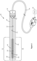
- FIG. 1 is a perspective view of a hair iron having arms in an open position according to one example embodiment.
- FIG. 2 is a perspective view of the hair iron shown in FIG. 1 with the arms in a closed position.
- FIG. 3 is an exploded perspective view of a heater assembly of the hair iron according to a first example embodiment.
- FIGS. 4 A and 4 B are plan views of an inner face and an outer face, respectively, of a heater of the heater assembly shown in FIG. 3 .
- FIG. 5 is a cross-sectional view of the heater shown in FIGS. 4 A and 4 B taken along line 5 - 5 in FIG. 4 A .
- FIG. 6 is an exploded perspective view of a heater assembly of the hair iron according to a second example embodiment.
- FIG. 7 is a plan view of an inner face of a heater of the heater assembly shown in FIG. 6 .
- FIG. 8 is a plan view of an outer face of a heater according to a thud example embodiment.
- Hair iron 100 may include an appliance such as a flat iron, straightening iron, curling iron, crimping iron, or other similar device that applies heat and pressure to a user's hair in order to change the structure or appearance of the user's hair.
- Hair iron 100 includes a housing 102 that forms the overall support structure of hair iron 100 .
- Housing 102 may be composed of, for example, a plastic that is thermally insulative and electrically insulative and that possesses relatively high heat resistivity and dimensional stability and low thermal mass.
- Example plastics include polybutylene terephthalate (PBT) plastics, polycarbonate/acrylonitrile butadiene styrene (PC/ABS) plastics, polyethylene terephthalate (PET) plastics, including glass-filled versions of each.
- housing 102 also provides electrical insulation and thermal insulation in order to provide a safe surface for the user to contact and hold during operation of hair iron 100 .
- Hair iron 100 includes a pair of arms 104 , 106 that are movable between an open position shown in FIG. 1 where distal segments 108 , 110 of arms 104 , 106 are spaced apart from each other and a closed position shown in FIG. 2 where distal segments 108 , 110 of arms 104 106 are in contact, or close proximity (e.g., within a few millimeters or less, including in contact), with each other.
- arms 104 , 106 are pivotable relative to each other about a pivot axis 112 between the open position and the closed position.
- Hair iron 100 may include a bias member (not shown), such as one or more springs, that biases one or both of arms 104 , 106 toward the open position such that user actuation is required to overcome the bias applied to arms 104 , 106 to bring arms 104 , 106 together to the closed position.
- a bias member such as one or more springs
- Hair iron 100 includes a heater positioned on an inner side 114 , 116 of one or both of arms 104 , 106 .
- Inner sides 114 , 116 of arms 104 , 106 include the portions of arms 104 , 106 that face each other when arms 104 106 are in the closed position shown in FIG. 2 .
- each arm 104 . 106 includes a respective heater 130 , 132 positioned on or within the arm 104 , 106 .
- Heaters 130 , 132 supply heat to respective contact surfaces 118 , 120 on arms 104 , 106 .
- Each contact surface 118 , 120 is positioned on inner side 114 , 116 of distal segment 108 , 110 of the corresponding arm 104 , 106 .
- Contact surfaces 118 , 120 may be formed directly by a surface of each heater 130 , 132 or formed by a material covering each heater 130 , 132 , such as a shield or sleeve. Contact surfaces 118 , 120 are positioned to directly contact and transfer heat to a user's hair upon the user positioning a portion of his or her hair between arms 104 , 106 and positioning arms 104 , 106 in the closed position. Contact surfaces 118 , 120 are positioned to mate against one another in a relatively flat orientation when arms 104 , 106 are in the closed position in order to maximize the surface area available for contacting the user's hair.
- Hair iron 100 includes control circuitry 122 configured to control the temperature of each heater 130 , 132 by selectively opening or closing a circuit supplying electrical current to resistors of each heater 130 , 132 (shown schematically in FIG. 2 ). Where hair iron 100 includes two heaters 130 , 132 , control circuitry 122 may be configured to control each heater 130 . 132 independently or to control both heaters 130 , 132 jointly. Open loop or, preferably, closed loop control may be utilized as desired. Control circuitry 122 may include a microprocessor, a microcontroller, an application-specific integrated circuit, and/or other form of integrated circuit. In the embodiment illustrated, hair iron 100 includes a power cord 124 for connecting hair iron 100 to an external voltage source 126 . In other embodiments, hair iron 100 may include an internal battery as desired.
- FIG. 3 shows an example heater assembly 140 that includes heater 130 and a sleeve 134 for use on arm 104 .
- a substantially identical heater assembly including heater 132 and corresponding sleeve may be used on arm 106 .
- Heater assembly 140 includes heater 130 , sleeve 134 and a heater housing 142 .
- Heater 130 is mounted to heater housing 142 with heater housing 142 physically supporting heater 130 .
- Heater housing 142 is, in turn, mounted to a portion of housing 102 within arm 104 .
- heater housing 142 includes a first housing portion 142 a and a second housing portion 142 b.
- Heater 130 is mounted to first housing portion 142 a.
- Heater housing 142 may be composed of, for example, a plastic that is thermally insulative and electrically insulative and that possesses relatively high heat resistivity and dimensional stability and low thermal mass. Due to the proximity to heater 130 , heater housing 142 is preferably composed of a plastic capable of resisting thermal degradation and maintaining sufficient strength and stiffness at high temperatures, including plastics having a maximum service temperature of 200 degrees Celsius or more.
- Example plastics include liquid crystal polymer (LCP) plastics, polyether ether ketone (PEEK) plastics and polyphenylene sulfide (PPS) plastics, including glass-filled versions of each.
- Heater 130 includes an outer face 150 that is exposed from and faces away from heater housing 142 as shown in FIG. 3 .
- Heater 130 includes an inner face 151 that is positioned proximate to an interior portion of heater housing 142 , for example, between first housing portion 142 a and second housing portion 142 b as shown in FIG. 3 .
- outer face 150 faces toward opposite arm 106 and inner face 151 faces away from opposite arm 106 .
- outer face 150 of heater 130 forms contact surface 118 .
- sleeve 134 is positioned against outer face 150 of heater 130 and forms contact surface 118 .
- sleeve 134 wraps around heater housing 142 and covers outer face 150 of heater 130 .
- Sleeve 134 is positioned in contact with, or in close proximity to, outer face 150 of heater 130 in order to transfer heat from outer face 150 of heater 130 to the user's hair during use.
- Sleeve 134 is composed of a thin film (e.g., less than 0.1 mm thick) material.
- sleeve 134 is composed of a thermally conductive and electrically insulative material, such as boron nitride filled polyimide. The thermal conductivity and relative thinness of sleeve 134 result in a relatively low thermal mass, which reduces the amount of time required to heat and cool sleeve 134 .
- sleeve 134 may be composed of unfilled to polyimide. In other embodiments, e.g., where electrical conductivity is acceptable, sleeve 134 may be composed of graphite filled polyimide. Sleeve 134 aids in protecting heater 130 from damage and also provides a relatively low friction contact surface 118 during use.
- FIGS. 4 A and 4 B show heater 130 removed from heater housing 142 .
- FIG. 4 A shows inner face 151 of heater 130
- FIG. 4 B shows outer face 150 of heater 130
- Heater 132 may be substantially identical to heater 130 .
- outer face 150 and inner face 151 are bordered by four sides or edges 152 , 153 , 154 , 155 each having a smaller surface area than outer face 150 and inner face 151 .
- heater 130 includes a longitudinal dimension 156 that extends from edge 152 to edge 153 and a lateral dimension 157 that extends from edge 154 to edge 155 .
- Heater 130 also includes an overall thickness 158 ( FIG. 5 ) measured from outer face 150 to inner face 151 .
- Heater 130 includes one or more layers of a ceramic substrate 160 , such as aluminum oxide (e.g., commercially available 96% aluminum oxide ceramic). Where heater 130 includes a single layer of ceramic substrate 160 , a thickness of ceramic substrate 160 may range from, for example, 0.5 mm to 1.5 mm, such as 1.0 mm. Where heater 130 includes multiple layers of ceramic substrate 160 , each layer may have a thickness ranging from, for example, 0.5 mm to 1.0 mm, such as 0.635 mm. In some embodiments, a length of ceramic substrate along longitudinal dimension 156 may range from, for example, 80 mm to 120 mm.
- a ceramic substrate 160 such as aluminum oxide (e.g., commercially available 96% aluminum oxide ceramic).
- a width of ceramic substrate 160 along lateral dimension 157 may range from, for example, 15 mm to 24 mm, such as 17 mm or 22.2 mm.
- Ceramic substrate 160 includes an outer face 162 that is oriented toward outer face 150 of heater 130 and an inner face 163 that is oriented toward inner face 151 of heater 130 .
- Outer face 162 and inner face 163 of ceramic substrate 160 are positioned on exterior portions of ceramic substrate 160 such that if more than one layer of ceramic substrate 160 is used, outer face 162 and inner face 163 are positioned on opposed external faces of the ceramic substrate 160 rather than on interior or intermediate layers of ceramic substrate 160 .
- outer face 150 of heater 130 is formed by outer face 162 of ceramic substrate 160 as shown in FIG. 4 B .
- inner face 163 of ceramic substrate 160 includes a series of one or more electrically resistive traces 164 and electrically conductive traces 166 positioned thereon.
- Resistive traces 164 include a suitable electrical resistor material such as, for example, silver palladium (e.g., blended 70/30 silver palladium).
- Conductive traces 166 include a suitable electrical conductor material such as, for example, silver platinum.
- resistive traces 164 and conductive traces 166 are applied to ceramic substrate 160 by way of thick film printing.
- resistive traces 164 may include a resistor paste having a thickness of 10-13 microns when applied to ceramic substrate 160
- conductive traces 166 may include a conductor paste having a thickness of 9-15 microns when applied to ceramic substrate 160 .
- Resistive traces 164 form the heating element of heater 130 and conductive traces 166 provide electrical connections to and between resistive traces 164 in order to supply an electrical current to each resistive trace 164 to generate heat.
- heater 130 includes a pair of resistive traces 164 a , 164 b that extend substantially parallel to each other (and substantially parallel to edges 154 , 155 ) along longitudinal dimension 156 of heater 130 .
- Heater 130 also includes a pair of conductive traces 166 a , 166 b that each form a respective terminal 168 a , 168 b of heater 130 .
- Cables or wires 170 a , 170 b are connected to terminals 168 a , 168 b in order to electrically connect resistive traces 164 and conductive traces 166 to, for example, control circuitry 122 and voltage source 126 in order to selectively close the circuit formed by resistive traces 164 and conductive traces 166 to generate heat.
- Conductive trace 166 a directly contacts resistive trace 164 a
- conductive trace 166 b directly contacts resistive trace 164 b .
- Conductive traces 166 a , 166 b are both positioned adjacent to edge 152 in the example embodiment illustrated, but conductive traces 166 a , 166 b may be positioned in other suitable locations on ceramic substrate 160 as desired.
- heater 130 includes a third conductive trace 166 c that electrically connects resistive trace 164 a to resistive trace 164 b . Portions of resistive traces 164 a , 164 b obscured beneath conductive traces 166 a , 166 b , 166 c in FIG. 4 A are shown in dotted line.
- current input to heater 130 at, for example, terminal 168 a by way of conductive trace 166 a passes through, in order, resistive trace 164 a , conductive trace 166 c , resistive trace 164 b , and conductive trace 166 b where it is output from heater 130 at terminal 168 b .
- Current input to heater 130 at terminal 168 b travels in reverse along the same path.
- heater 130 includes a thermistor 172 positioned in close proximity to a surface of heater 130 in order to provide feedback regarding the temperature of heater 130 to control circuitry 122 .
- thermistor 172 is positioned on inner face 163 of ceramic substrate 160 .
- thermistor 172 is welded directly to inner face 163 of ceramic substrate 160 .
- heater 130 also includes a pair of conductive traces 174 a, 174 b that are each electrically connected to a respective terminal of thermistor 172 and that each form a respective terminal 176 a, 176 b .
- thermistor 172 is positioned at a central location of inner face 163 of ceramic substrate 160 , between resistive traces 164 a, 164 b and midway from edge 152 to edge 153 .
- conductive traces 174 a, 174 b are also positioned between resistive traces 164 a, 164 b with conductive trace 174 a positioned toward edge 152 from thermistor 172 and conductive trace 174 b positioned toward edge 153 from thermistor 172 .
- thermistor 172 and its corresponding conductive traces 174 a, 174 b may be positioned in other suitable locations on ceramic substrate 160 so long as they do not interfere with the positioning of resistive traces 164 and conductive traces 166 .
- FIG. 5 is a cross-sectional view of heater 130 taken along line 5 - 5 in FIG. 4 A .
- heater 130 includes one or more layers of printed glass 180 on inner face 163 of ceramic substrate 160 .
- glass 180 covers resistive traces 164 a, 164 b, conductive trace 166 c, and portions of conductive traces 166 a, 166 b in order to electrically insulate such features to prevent electric shock or arcing.
- the borders of glass layer 180 are shown in dashed line in FIG. 4 A .
- glass 180 does not cover thermistor 172 or conductive traces 174 a, 174 b because the relatively low voltage applied to such features presents a lower risk of electric shock or arcing.
- An overall thickness of glass 180 may range from, for example, 70-80 microns.
- FIG. 5 shows glass 180 covering resistive traces 164 a, 164 b and adjacent portions of ceramic substrate 160 such that glass 180 forms the majority of inner face 151 of heater 130 .
- Outer face 162 of ceramic substrate 160 is shown forming outer face 150 of heater 130 as discussed above.
- Conductive trace 166 c which is obscured from view in FIG. 5 by portions of glass 180 , is shown in dotted line.
- FIG. 5 depicts a single layer of ceramic substrate 160 . However, ceramic substrate 160 may include multiple layers as depicted by dashed line 182 in FIG. 5 .
- Heater 130 may be constructed by way of thick film printing.
- resistive traces 164 are printed on fired (not green state) ceramic substrate 160 , which includes selectively applying a paste containing resistor material to ceramic substrate 160 to through a patterned mesh screen with a squeegee or the like.
- the printed resistor is then allowed to settle on ceramic substrate 160 at room temperature.
- the ceramic substrate 160 having the printed resistor is then heated at, for example, approximately 140-160 degrees Celsius for a total of approximately 30 minutes, including approximately 10-15 minutes at peak temperature and the remaining time ramping up to and down from the peak temperature, in order to dry the resistor paste and to temporarily fix resistive traces 164 in position.
- the ceramic substrate 160 having temporary resistive traces 164 is then heated at, for example, approximately 850 degrees Celsius for a total of approximately one hour, including approximately 10 minutes at peak temperature and the remaining time ramping up to and down from the peak temperature, in order to permanently fix resistive traces 164 in position.
- Conductive traces 166 and 174 a, 174 b are then printed on ceramic substrate 160 , which includes selectively applying a paste containing conductor material in the same manner as the resistor material.
- the ceramic substrate 160 having the printed resistor and conductor is then allowed to settle, dried and fired in the same manner as discussed above with respect to resistive traces 164 in order to permanently fix conductive traces 166 and 174 a, 174 b in position.
- Glass layer(s) 180 are then printed in substantially the same manner as the resistors and conductors, including allowing the glass layer(s) 180 to settle as well as drying and firing the glass layer(s) 180 .
- glass layer(s) 180 are fired at a peak temperature of approximately 810 degrees Celsius, slightly lower than the resistors and conductors.
- Thermistor 172 is then mounted to ceramic substrate 160 in a finishing operation with the terminals of thermistor 172 directly welded to conductive traces 174 a, 174 b.
- Thick film printing resistive traces 164 and conductive traces 166 on fired ceramic substrate 160 provides more uniform resistive and conductive traces in comparison with conventional ceramic heaters, which include resistive and conductive traces printed on green state ceramic.
- the improved uniformity of resistive traces 164 and conductive traces 166 provides more uniform heating across contact surface 118 as well as more predictable heating of heater 130 .
- heaters 130 are produced in an array for cost efficiency. Heaters 130 are separated into individual heaters 130 after the construction of all heaters 130 is completed, including firing of all components and any applicable finishing operations. In some embodiments, individual heaters 130 are separated from the array by way of fiber laser scribing. Fiber laser scribing tends to provide a more uniform singulation surface having fewer microcracks along the separated edge in comparison with conventional carbon dioxide laser scribing.
- resistive traces 164 and thermistor 172 may be positioned on outer face 162 of ceramic substrate 160 along with corresponding conductive traces as needed to establish electrical connections thereto.
- Glass 180 may cover the resistive traces and conductive traces on outer face 162 and/or inner face 163 of ceramic substrate 160 as desired in order to electrically insulate such features.
- FIGS. 6 and 7 show a heater assembly 1140 suitable for use with hair iron 100 according to another example embodiment.
- heater assembly 1140 includes a heater 1130 mounted to a heater housing 1142 similar to heater 130 and heater housing 142 discussed above.
- Heater 1130 includes an outer face 1150 that is exposed from and faces away from heater housing 1142 and an inner face 1151 that is positioned proximate to an interior portion of heater housing 1142 as discussed above.
- Heater assembly 1140 also includes a sleeve 1134 , similar to sleeve 134 discussed above, that covers heater 1130 .
- Heater 1130 includes one or more layers of ceramic substrate 1160 as discussed above.
- Ceramic substrate 1160 includes an outer face 1162 that is oriented toward outer face 1150 of heater 1130 and an inner face 1163 that is oriented toward inner face 1151 of heater 1130 .
- electrically resistive traces 1164 and electrically conductive traces 1166 are positioned on outer face 1162 of ceramic substrate 1160 , rather than inner face 1163 . Resistive traces 1164 and conductive traces 1166 may be applied by way of thick film printing as discussed above.
- heater 1130 includes a pair of resistive traces 1164 a, 1164 b on outer face 1162 of a ceramic substrate 1160 .
- Resistive traces 1164 a, 1164 b extend substantially parallel to each other along a longitudinal dimension 1156 of heater 1130 .
- Heater 1130 also includes three conductive traces 1166 a, 1166 b , 1166 c positioned on outer face 1162 of ceramic substrate 1160 .
- Conductive trace 1166 a directly contacts resistive trace 1164 a
- conductive trace 1166 b directly contacts resistive trace 1164 b .
- Conductive traces 1166 a, 1166 b are both positioned adjacent to a common edge of ceramic substrate 1160 in the example embodiment illustrated.
- Conductive trace 1166 c is positioned adjacent to an opposite edge of ceramic substrate 1160 (relative to conductive traces 1166 a , 1166 b ) and electrically connects resistive trace 1164 a to resistive trace 1164 b. Portions of resistive traces 1164 a, 1164 b obscured beneath conductive traces 1166 a, 1166 b, 1166 c in FIG. 6 are shown in dotted line.
- heater 1130 includes a pair of vias 1190 a, 1190 b that are formed as through-holes substantially filled with conductive material extending through ceramic substrate 1160 from outer face 1162 to inner face 1163 .
- Vias 1190 a, 1190 b electrically connect conductive traces 1166 a, 1166 b to corresponding conductive traces on inner face 1163 of ceramic substrate 1160 as discussed below.
- heater 1130 includes one or more layers of printed glass 1180 on outer face 1162 of ceramic substrate 1160 .
- glass 1180 covers resistive traces 1164 a, 1164 b and conductive traces 1166 a, 1166 b, 1166 c in order to electrically insulate these features.
- the borders of glass layer 1180 are shown in dashed line in FIG. 6 .
- FIG. 7 shows inner face 1151 of heater 1130 according to one example embodiment.
- heater 1130 includes a pair of conductive traces 1192 a, 1192 b positioned on inner face 1163 of ceramic substrate 1160 that that each form a respective terminal 1168 a, 1168 b of heater 1130 .
- Each conductive trace 1192 a, 1192 b on inner face 1163 of ceramic substrate 1160 is electrically connected to a respective conductive trace 1166 a, 1166 b on outer face 1162 of ceramic substrate 1160 by a respective via 1190 a, 1190 b.
- Cables or wires 1170 a , 1170 b are connected to (e.g., directly welded to) terminals 1168 a, 1168 b in order to supply current to resistive traces 1164 a, 1164 b to generate heat.
- current input to heater 1130 at, for example, terminal 1168 a by way of conductive trace 1192 a passes through, in order, via 1190 a, conductive trace 1166 a, resistive trace 1164 a, conductive trace 1166 c, resistive trace 1164 b, conductive trace 1166 b , via 1190 b and conductive trace 1192 b where it is output from heater 1130 at terminal 1168 b.
- Current input to heater 1130 at terminal 1168 b travels in reverse along the same path.
- heater 1130 includes a thermistor 1172 positioned in close proximity to inner face 1163 of ceramic substrate 1160 in order to provide feedback regarding the temperature of heater 1130 to control circuitry 122 .
- thermistor 1172 is not directly attached to ceramic substrate 1160 but is instead held against inner face 1163 of ceramic substrate 1160 by a mounting clip (not shown) or other form of fixture or attachment mechanism. Cables or wires 1178 a, 1178 b are connected to (e.g., directly welded to) respective terminals of thermistor 1172 in order to electrically connect thermistor 1172 to, for example, control circuitry 122 .
- thermistor 1172 of heater 1130 may alternatively be directly welded to ceramic substrate 1160 as discussed above with respect to thermistor 172 of heater 130 .
- thermistor 172 of heater 130 may be held against ceramic substrate 160 by a fixture instead of directly welded to ceramic substrate 160 .
- heater 1130 also includes a thermal cutoff 1194 , such as a bi-metal thermal cutoff, positioned on inner face 1163 of ceramic substrate 1160 .
- Cables or wires 1196 a, 1196 b are connected to respective terminals of thermal cutoff 1194 in order to provide electrical connections to thermal cutoff 1194 .
- Thermal cutoff 1194 is electrically connected in series with the heating circuit formed by resistive traces 1164 and conductive traces 1166 permitting thermal cutoff 1194 to open the heating circuit formed by resistive traces 1164 and conductive traces 1166 upon detection by thermal cutoff 1194 of a temperature that exceeds a predetermined amount. In this manner, thermal cutoff 1194 provides additional safety by preventing overheating of heater 1130 .
- heater 130 discussed above may also include a thermal cutoff as desired.
- inner face 1163 of ceramic substrate 1160 may include one or more glass layers in order to electrically insulate portions of inner face 1151 of heater 1130 as desired.
- FIG. 8 shows a heater 2130 suitable for use with hair iron 100 according to another example embodiment.
- FIG. 8 shows an outer face 2150 of heater 2130 .
- an inner face of heater 2130 is substantially the same as inner face 1151 of heater 1130 shown in FIG. 7 .
- Heater 2130 includes one or more layers of a ceramic substrate 2160 as discussed above.
- FIG. 8 shows an outer face 2162 of ceramic substrate 2160 .
- heater 2130 includes a single resistive trace 2164 on outer face 2162 of ceramic substrate 2160 . Resistive trace 2164 extends along a longitudinal dimension 2156 of heater 2130 . Heater 2130 also includes a pair of conductive traces 2166 a, 2166 b positioned on outer face 2162 of ceramic substrate 2160 . Each conductive trace 2166 a, 2166 b directly contacts a respective end of resistive trace 2164 . Conductive trace 2166 a contacts resistive trace 2164 near a first longitudinal edge 2152 of heater 2130 .
- Conductive trace 2166 b contacts resistive trace 2164 near a second longitudinal edge 2153 of heater 2130 and extends from the point of contact with resistive trace 2164 to a position next to conductive trace 2166 a. Portions of resistive trace 2164 obscured beneath conductive traces 2166 a, 2166 b in FIG. 8 are shown in dotted line.
- heater 2130 includes a pair of vias 2190 a, 2190 b that are formed as through-holes substantially tilled with conductive material extending through ceramic substrate 2160 as discussed above with respect to heater 1130 .
- Vias 2190 a, 2190 b electrically connect conductive traces 2166 a, 2166 b to corresponding conductive traces on the inner face of ceramic substrate 2160 as discussed above.
- heater 2130 includes one or more layers of printed glass 2180 on outer face 2162 of ceramic substrate 2160 .
- Glass 2180 covers resistive trace 2164 and conductive traces 2166 a, 2166 b in order to electrically insulate these features as discussed above.
- the borders of glass layer 2180 are shown in dashed line in FIG. 8 .
- the heater of the present disclosure may include resistive and conductive traces in many different geometries, including resistive traces on the outer face and/or the inner face of the heater, as desired.
- Other components e.g., a thermistor
- the present disclosure provides a ceramic heater having a low thermal mass in comparison with the heaters of conventional hair irons.
- thick film printed resistive traces on an exterior face (outer or inner) of the ceramic substrate provides reduced thermal mass in comparison with resistive traces positioned internally between multiple sheets of ceramic.
- the use of a thin film, thermally conductive sleeve also provides reduced thermal mass in comparison with metal holders, guides, etc.
- the low thermal mass of the ceramic heater of the present disclosure allows the heater, in some embodiments, to heat to an effective temperature for use in a matter of seconds (e.g., less than 5 seconds), significantly faster than conventional hair irons.
- the low thermal mass of the ceramic heater of the present disclosure also allows the heater, in some embodiments, to cool to a safe temperature after use in a matter of seconds (e.g., less than 5 seconds), again, significantly faster than conventional hair irons.
- embodiments of the hair iron of the present disclosure operate at a more precise and more uniform temperature than conventional hair irons because of the closed loop temperature control provided by the thermistor in combination with the relatively uniform thick film printed resistive and conductive traces.
- the low thermal mass of the ceramic heater and improved temperature control permit greater energy efficiency in comparison with conventional hair irons.
- the rapid warmup and cooldown times of the ceramic heater of the present disclosure also provide increased safety by reducing the amount of time the hair iron is hot but unused.
- the improved temperature control and temperature uniformity further increase safety by reducing the occurrence of overheating.
- the improved temperature control and temperature uniformity also improve the performance of the hair iron of the present disclosure.
Landscapes
- Engineering & Computer Science (AREA)
- Microelectronics & Electronic Packaging (AREA)
- Resistance Heating (AREA)
Abstract
Description
Claims (20)
Priority Applications (7)
| Application Number | Priority Date | Filing Date | Title |
|---|---|---|---|
| US16/782,308 US11903472B2 (en) | 2019-02-08 | 2020-02-05 | Hair iron having a ceramic heater |
| EP20752962.9A EP3920750B1 (en) | 2019-02-08 | 2020-02-06 | Hair iron having a ceramic heater |
| PCT/US2020/016926 WO2020163555A1 (en) | 2019-02-08 | 2020-02-06 | Hair iron having a ceramic heater |
| CA3127690A CA3127690A1 (en) | 2019-02-08 | 2020-02-06 | Hair iron having a ceramic heater |
| CN202080012649.9A CN113473881B (en) | 2019-02-08 | 2020-02-06 | Hair iron with ceramic heater |
| JP2021544773A JP7472419B2 (en) | 2019-02-08 | 2020-02-06 | Hair iron with ceramic heater |
| US18/401,932 US20240130501A1 (en) | 2019-02-08 | 2024-01-02 | Hair iron having a ceramic heater |
Applications Claiming Priority (2)
| Application Number | Priority Date | Filing Date | Title |
|---|---|---|---|
| US201962802945P | 2019-02-08 | 2019-02-08 | |
| US16/782,308 US11903472B2 (en) | 2019-02-08 | 2020-02-05 | Hair iron having a ceramic heater |
Related Child Applications (1)
| Application Number | Title | Priority Date | Filing Date |
|---|---|---|---|
| US18/401,932 Continuation US20240130501A1 (en) | 2019-02-08 | 2024-01-02 | Hair iron having a ceramic heater |
Publications (2)
| Publication Number | Publication Date |
|---|---|
| US20200253350A1 US20200253350A1 (en) | 2020-08-13 |
| US11903472B2 true US11903472B2 (en) | 2024-02-20 |
Family
ID=71946483
Family Applications (2)
| Application Number | Title | Priority Date | Filing Date |
|---|---|---|---|
| US16/782,308 Active 2042-08-08 US11903472B2 (en) | 2019-02-08 | 2020-02-05 | Hair iron having a ceramic heater |
| US18/401,932 Pending US20240130501A1 (en) | 2019-02-08 | 2024-01-02 | Hair iron having a ceramic heater |
Family Applications After (1)
| Application Number | Title | Priority Date | Filing Date |
|---|---|---|---|
| US18/401,932 Pending US20240130501A1 (en) | 2019-02-08 | 2024-01-02 | Hair iron having a ceramic heater |
Country Status (6)
| Country | Link |
|---|---|
| US (2) | US11903472B2 (en) |
| EP (1) | EP3920750B1 (en) |
| JP (1) | JP7472419B2 (en) |
| CN (1) | CN113473881B (en) |
| CA (1) | CA3127690A1 (en) |
| WO (1) | WO2020163555A1 (en) |
Families Citing this family (5)
| Publication number | Priority date | Publication date | Assignee | Title |
|---|---|---|---|---|
| US11692754B2 (en) | 2020-04-21 | 2023-07-04 | Lexmark International, Inc. | Ice maker heater assemblies |
| US11828490B2 (en) | 2020-04-24 | 2023-11-28 | Lexmark International, Inc. | Ceramic heater for heating water in an appliance |
| US20230284392A1 (en) * | 2022-03-04 | 2023-09-07 | Lexmark International, Inc. | Thick film printed heat spreader for low thermal mass heating solutions |
| GB2634278A (en) * | 2023-10-04 | 2025-04-09 | Jemella Ltd | Heater apparatus and method |
| GB2635405A (en) * | 2023-11-13 | 2025-05-14 | Dyson Technology Ltd | Heater assembly |
Citations (49)
| Publication number | Priority date | Publication date | Assignee | Title |
|---|---|---|---|---|
| US3878362A (en) | 1974-02-15 | 1975-04-15 | Du Pont | Electric heater having laminated structure |
| US4222026A (en) | 1979-01-22 | 1980-09-09 | Ford Motor Company | Exhaust gas sensor having two titania ceramic elements |
| US4733056A (en) | 1985-08-23 | 1988-03-22 | Ngk Spark Plug Co., Ltd. | Heater backed with a ceramic substrate |
| US5221829A (en) | 1990-10-15 | 1993-06-22 | Shimon Yahav | Domestic cooking apparatus |
| US5581876A (en) | 1995-01-27 | 1996-12-10 | David Sarnoff Research Center, Inc. | Method of adhering green tape to a metal support substrate with a bonding glass |
| WO1997001259A1 (en) | 1995-06-21 | 1997-01-09 | Strix Limited | Printed heating elements |
| US5663702A (en) | 1995-06-07 | 1997-09-02 | Littelfuse, Inc. | PTC electrical device having fuse link in series and metallized ceramic electrodes |
| US5968391A (en) | 1998-05-06 | 1999-10-19 | Emerson Electric Company | Modular radiant heating unit |
| US6222158B1 (en) | 1992-12-29 | 2001-04-24 | Canon Kabushiki Kaisha | Fixing heater comprising electrically conductive member extending in the longitudinal axis of substrate |
| CN2502618Y (en) | 2001-10-18 | 2002-07-31 | 宁波海菱电器有限公司 | Soya-bean milk machine |
| US6433317B1 (en) | 2000-04-07 | 2002-08-13 | Watlow Polymer Technologies | Molded assembly with heating element captured therein |
| US20020145134A1 (en) | 2001-03-09 | 2002-10-10 | Tim Olding | Sol-gel derived resistive and conductive coating |
| US6518549B1 (en) | 1998-05-11 | 2003-02-11 | Christopher R. Taylor | Modular radiant heater units for use in grills having edge heat weighting |
| US20030186183A1 (en) * | 1999-12-09 | 2003-10-02 | Yasutaka Ito | Ceramic plate for a semiconductor producing/inspecting apparatus |
| US20040149718A1 (en) | 2000-04-07 | 2004-08-05 | Yasutaka Ito | Ceramic heater |
| US20050205548A1 (en) | 2004-01-29 | 2005-09-22 | Tim Olding | Integrated thin high temperature heaters |
| US6960741B2 (en) | 2002-08-26 | 2005-11-01 | Lexmark International, Inc. | Large area alumina ceramic heater |
| US20060065654A1 (en) | 2004-09-30 | 2006-03-30 | Watlow Electric Manufacturing Compamy | Modular layered heater system |
| WO2006054080A2 (en) | 2004-11-19 | 2006-05-26 | Jemella Limited | Improvements in and relating to hair irons |
| US20060127686A1 (en) | 2004-12-15 | 2006-06-15 | Meloni Paul A | Thermally conductive polyimide film composites having high thermal conductivity useful in an electronic device |
| CN2847768Y (en) | 2005-12-09 | 2006-12-13 | 珠海佳一电子技术有限公司 | Constant temperature heating plate |
| US20070119844A1 (en) | 2005-11-25 | 2007-05-31 | Beauti-Gear International Limited | Ceramic hair care heating element |
| US7241131B1 (en) | 2000-06-19 | 2007-07-10 | Husky Injection Molding Systems Ltd. | Thick film heater apparatus |
| US20070278203A1 (en) | 2006-06-02 | 2007-12-06 | Gregory Daniel Creteau | Heater assembly including housing with strain relief features |
| US7336919B2 (en) | 2005-06-16 | 2008-02-26 | Lexmark International, Inc. | Multilayer fuser member including current elements |
| US7352988B2 (en) | 2005-06-16 | 2008-04-01 | Lexmark International, Inc. | Fuser member including an electrically conductive polymer layer, a resistive layer, an electrically conductive layer, and current elements |
| US20080083733A1 (en) | 2006-08-29 | 2008-04-10 | Toshihiro Takai | Radiant heater |
| CN201076357Y (en) | 2007-07-13 | 2008-06-25 | 东莞市乐邦电子有限公司 | Food processing device |
| US20080224786A1 (en) | 2007-03-13 | 2008-09-18 | Stolpman James L | Apparatus and method for temperature compensating an ovenized oscillator |
| CN101327102A (en) | 2007-04-30 | 2008-12-24 | 美国哈普蓝思公司 | Mincing machine for kitchen |
| US20090044823A1 (en) * | 2005-11-18 | 2009-02-19 | Paul Overend | Hair irons |
| US7671300B2 (en) | 2006-08-30 | 2010-03-02 | Lexmark International, Inc. | Fuser assembly having heater element with spaced-apart features |
| US20100124448A1 (en) | 2008-11-14 | 2010-05-20 | Bradley Leonard Beach | Resistive Heating Hot Roll Fuser |
| US8064816B2 (en) | 2008-03-26 | 2011-11-22 | Lexmark International, Inc. | Printer including a fuser assembly with backup member temperature sensor |
| WO2012139958A1 (en) | 2011-04-14 | 2012-10-18 | BSH Bosch und Siemens Hausgeräte GmbH | Hair-shaping-appliance heating plate |
| US20130098389A1 (en) * | 2011-10-24 | 2013-04-25 | Izumi Uwano | Low Voltage Hair Iron |
| US20140369730A1 (en) | 2013-06-13 | 2014-12-18 | Lexmark International, Inc. | Heat Transfer System for a Fuser Assembly |
| US20150335120A1 (en) * | 2012-06-25 | 2015-11-26 | Jamella Limited | Hair Styling Appliance |
| US20160219651A1 (en) | 2013-10-11 | 2016-07-28 | Illinois Tool Works Inc. | Thick layer heating element and kitchen appliance comprising such a heating element |
| US9417572B2 (en) | 2010-12-17 | 2016-08-16 | Lexmark International, Inc. | Fuser heating element for an electrophotographic imaging device |
| US9551962B2 (en) | 2010-12-17 | 2017-01-24 | Lexmark International, Inc. | Hybrid heater with dual function heating capability |
| US20170023894A1 (en) | 2015-07-20 | 2017-01-26 | Lexmark International, Inc. | Heater Member for the Fuser Assembly of an Electrophotographic Imaging Device |
| US9848683B2 (en) | 2012-08-20 | 2017-12-26 | Jemella Limited | Hair styling device |
| US20180014618A1 (en) * | 2016-07-13 | 2018-01-18 | Ohgi Technological Creation Co., Ltd. | Hair iron |
| US20190290877A1 (en) | 2009-06-05 | 2019-09-26 | Fisher & Paykel Healthcare Limited | Humidifier heater base |
| US20190357318A1 (en) | 2018-05-18 | 2019-11-21 | Hatco Corporation | Temperature-regulating appliance with removable base |
| US20200063975A1 (en) | 2018-08-21 | 2020-02-27 | Lg Electronics Inc. | Electric heater |
| US20200253409A1 (en) * | 2019-02-08 | 2020-08-13 | Lexmark International, Inc. | Cooking device having a cooking vessel and a ceramic heater |
| US20210251046A1 (en) * | 2020-02-10 | 2021-08-12 | Lexmark International, Inc. | Cooking device having a modular ceramic heater |
Family Cites Families (5)
| Publication number | Priority date | Publication date | Assignee | Title |
|---|---|---|---|---|
| WO2006001373A1 (en) * | 2004-06-25 | 2006-01-05 | Kyocera Corporation | Ceramic heater and production method therefor and heating device and hair iron |
| KR100858028B1 (en) * | 2008-04-17 | 2008-09-10 | 불루세라믹 주식회사 | Hair beauty instruments |
| WO2009152155A1 (en) * | 2008-06-09 | 2009-12-17 | Conair Corporation | Dual mode flat iron |
| US20150086231A1 (en) * | 2013-09-26 | 2015-03-26 | Lexmark International, Inc. | Fuser Assembly with Automatic Media Width Sensing and Thermal Compensation |
| FR3015875B1 (en) * | 2013-12-26 | 2017-01-13 | Oreal | DEVICE FOR TREATING THE HAIR |
-
2020
- 2020-02-05 US US16/782,308 patent/US11903472B2/en active Active
- 2020-02-06 JP JP2021544773A patent/JP7472419B2/en active Active
- 2020-02-06 EP EP20752962.9A patent/EP3920750B1/en active Active
- 2020-02-06 WO PCT/US2020/016926 patent/WO2020163555A1/en not_active Ceased
- 2020-02-06 CA CA3127690A patent/CA3127690A1/en active Pending
- 2020-02-06 CN CN202080012649.9A patent/CN113473881B/en active Active
-
2024
- 2024-01-02 US US18/401,932 patent/US20240130501A1/en active Pending
Patent Citations (58)
| Publication number | Priority date | Publication date | Assignee | Title |
|---|---|---|---|---|
| US3878362A (en) | 1974-02-15 | 1975-04-15 | Du Pont | Electric heater having laminated structure |
| US4222026A (en) | 1979-01-22 | 1980-09-09 | Ford Motor Company | Exhaust gas sensor having two titania ceramic elements |
| US4733056A (en) | 1985-08-23 | 1988-03-22 | Ngk Spark Plug Co., Ltd. | Heater backed with a ceramic substrate |
| US5221829A (en) | 1990-10-15 | 1993-06-22 | Shimon Yahav | Domestic cooking apparatus |
| US6222158B1 (en) | 1992-12-29 | 2001-04-24 | Canon Kabushiki Kaisha | Fixing heater comprising electrically conductive member extending in the longitudinal axis of substrate |
| US5581876A (en) | 1995-01-27 | 1996-12-10 | David Sarnoff Research Center, Inc. | Method of adhering green tape to a metal support substrate with a bonding glass |
| US5663702A (en) | 1995-06-07 | 1997-09-02 | Littelfuse, Inc. | PTC electrical device having fuse link in series and metallized ceramic electrodes |
| WO1997001259A1 (en) | 1995-06-21 | 1997-01-09 | Strix Limited | Printed heating elements |
| US5968391A (en) | 1998-05-06 | 1999-10-19 | Emerson Electric Company | Modular radiant heating unit |
| US6518549B1 (en) | 1998-05-11 | 2003-02-11 | Christopher R. Taylor | Modular radiant heater units for use in grills having edge heat weighting |
| US20030186183A1 (en) * | 1999-12-09 | 2003-10-02 | Yasutaka Ito | Ceramic plate for a semiconductor producing/inspecting apparatus |
| US20040149718A1 (en) | 2000-04-07 | 2004-08-05 | Yasutaka Ito | Ceramic heater |
| US6433317B1 (en) | 2000-04-07 | 2002-08-13 | Watlow Polymer Technologies | Molded assembly with heating element captured therein |
| US7241131B1 (en) | 2000-06-19 | 2007-07-10 | Husky Injection Molding Systems Ltd. | Thick film heater apparatus |
| US20020145134A1 (en) | 2001-03-09 | 2002-10-10 | Tim Olding | Sol-gel derived resistive and conductive coating |
| CN2502618Y (en) | 2001-10-18 | 2002-07-31 | 宁波海菱电器有限公司 | Soya-bean milk machine |
| US6960741B2 (en) | 2002-08-26 | 2005-11-01 | Lexmark International, Inc. | Large area alumina ceramic heater |
| US20060096084A1 (en) | 2002-08-26 | 2006-05-11 | Hamilton Douglas C | Large area alumina ceramic heater |
| US7005611B2 (en) | 2002-08-26 | 2006-02-28 | Lexmark International, Inc. | Large area alumina ceramic heater |
| US20050205548A1 (en) | 2004-01-29 | 2005-09-22 | Tim Olding | Integrated thin high temperature heaters |
| US20060065654A1 (en) | 2004-09-30 | 2006-03-30 | Watlow Electric Manufacturing Compamy | Modular layered heater system |
| US20090272732A1 (en) | 2004-09-30 | 2009-11-05 | Watlow Electric Manufacturing Company | Modular layered heater system |
| WO2006054080A2 (en) | 2004-11-19 | 2006-05-26 | Jemella Limited | Improvements in and relating to hair irons |
| US20060127686A1 (en) | 2004-12-15 | 2006-06-15 | Meloni Paul A | Thermally conductive polyimide film composites having high thermal conductivity useful in an electronic device |
| US7336919B2 (en) | 2005-06-16 | 2008-02-26 | Lexmark International, Inc. | Multilayer fuser member including current elements |
| US7352988B2 (en) | 2005-06-16 | 2008-04-01 | Lexmark International, Inc. | Fuser member including an electrically conductive polymer layer, a resistive layer, an electrically conductive layer, and current elements |
| US20090044823A1 (en) * | 2005-11-18 | 2009-02-19 | Paul Overend | Hair irons |
| US20070119844A1 (en) | 2005-11-25 | 2007-05-31 | Beauti-Gear International Limited | Ceramic hair care heating element |
| CN2847768Y (en) | 2005-12-09 | 2006-12-13 | 珠海佳一电子技术有限公司 | Constant temperature heating plate |
| US20070278203A1 (en) | 2006-06-02 | 2007-12-06 | Gregory Daniel Creteau | Heater assembly including housing with strain relief features |
| US20080083733A1 (en) | 2006-08-29 | 2008-04-10 | Toshihiro Takai | Radiant heater |
| US7671300B2 (en) | 2006-08-30 | 2010-03-02 | Lexmark International, Inc. | Fuser assembly having heater element with spaced-apart features |
| US20080224786A1 (en) | 2007-03-13 | 2008-09-18 | Stolpman James L | Apparatus and method for temperature compensating an ovenized oscillator |
| CN101327102A (en) | 2007-04-30 | 2008-12-24 | 美国哈普蓝思公司 | Mincing machine for kitchen |
| CN201076357Y (en) | 2007-07-13 | 2008-06-25 | 东莞市乐邦电子有限公司 | Food processing device |
| US8064816B2 (en) | 2008-03-26 | 2011-11-22 | Lexmark International, Inc. | Printer including a fuser assembly with backup member temperature sensor |
| US20100124448A1 (en) | 2008-11-14 | 2010-05-20 | Bradley Leonard Beach | Resistive Heating Hot Roll Fuser |
| US20190290877A1 (en) | 2009-06-05 | 2019-09-26 | Fisher & Paykel Healthcare Limited | Humidifier heater base |
| US10025244B2 (en) | 2010-12-17 | 2018-07-17 | Lexmark International, Inc. | Circuit and method for a hybrid heater with dual function heating capability |
| US9417572B2 (en) | 2010-12-17 | 2016-08-16 | Lexmark International, Inc. | Fuser heating element for an electrophotographic imaging device |
| US9551962B2 (en) | 2010-12-17 | 2017-01-24 | Lexmark International, Inc. | Hybrid heater with dual function heating capability |
| EP2696720B1 (en) | 2011-04-14 | 2017-12-27 | BSH Hausgeräte GmbH | Hair-shaping-appliance heating plate |
| WO2012139958A1 (en) | 2011-04-14 | 2012-10-18 | BSH Bosch und Siemens Hausgeräte GmbH | Hair-shaping-appliance heating plate |
| US20130098389A1 (en) * | 2011-10-24 | 2013-04-25 | Izumi Uwano | Low Voltage Hair Iron |
| US20150335120A1 (en) * | 2012-06-25 | 2015-11-26 | Jamella Limited | Hair Styling Appliance |
| EP2863769B1 (en) * | 2012-06-25 | 2017-08-09 | Jemella Limited | Hair styling appliance |
| US9848683B2 (en) | 2012-08-20 | 2017-12-26 | Jemella Limited | Hair styling device |
| US20140369730A1 (en) | 2013-06-13 | 2014-12-18 | Lexmark International, Inc. | Heat Transfer System for a Fuser Assembly |
| US20160219651A1 (en) | 2013-10-11 | 2016-07-28 | Illinois Tool Works Inc. | Thick layer heating element and kitchen appliance comprising such a heating element |
| US10274876B2 (en) | 2015-07-20 | 2019-04-30 | Lexmark International, Inc. | Heater member for the fuser assembly of an electrophotographic imaging device |
| US20190196372A1 (en) | 2015-07-20 | 2019-06-27 | Lexmark International, Inc. | Heater member for the fuser assembly of an electrophotographic imaging device |
| US20170023894A1 (en) | 2015-07-20 | 2017-01-26 | Lexmark International, Inc. | Heater Member for the Fuser Assembly of an Electrophotographic Imaging Device |
| US20180014618A1 (en) * | 2016-07-13 | 2018-01-18 | Ohgi Technological Creation Co., Ltd. | Hair iron |
| US20190357318A1 (en) | 2018-05-18 | 2019-11-21 | Hatco Corporation | Temperature-regulating appliance with removable base |
| US20200063975A1 (en) | 2018-08-21 | 2020-02-27 | Lg Electronics Inc. | Electric heater |
| US20200253409A1 (en) * | 2019-02-08 | 2020-08-13 | Lexmark International, Inc. | Cooking device having a cooking vessel and a ceramic heater |
| US20210251046A1 (en) * | 2020-02-10 | 2021-08-12 | Lexmark International, Inc. | Cooking device having a modular ceramic heater |
| US20210251045A1 (en) * | 2020-02-10 | 2021-08-12 | Lexmark International, Inc. | Modular ceramic heater |
Non-Patent Citations (12)
| Title |
|---|
| English translation of Office Action dated May 4, 2023 for China Patent Application No. 2020800126499. |
| EPO machine translation of CN 2847768 Y (Jyayi Electric Technology Co. Ltd.). |
| EPO machine translation of WO 2012139958 A1 (Copitzky et al.). |
| Extended European Search Report dated Sep. 29, 2022 for European Patent Application No. 20752962.9. |
| Final Office Action dated Apr. 5, 2023 for U.S. Appl. No. 17/147,921 (Smith et al.). |
| Final Office Action dated Jul. 19, 2023 for U.S. Appl. No. 17/147,907 (Smith et al.). |
| International Search Report and Written Opinion of the International Searching Authority dated Apr. 24, 2020 for PCT Application No. PCT/US2020/016926. |
| International Search Report and Written Opinion of the International Searching Authority dated Jul. 19, 2021 for PCT Application No. PCT/US2021/025721. |
| Non-Final Office Action dated Jan. 3, 2023 for U.S. Appl. No. 17/147,921 (Smith et al.). |
| Non-Final Office Action dated Mar. 6, 2023 for U.S. Appl. No. 17/147,907 (Smith et al.). |
| Non-Final Office Action dated Sep. 29, 2023 for U.S. Appl. No. 17/147,907 (Smith et al.). |
| Office Action dated Nov. 8, 2023 for Canada Patent Application No. 3,127,690. |
Also Published As
| Publication number | Publication date |
|---|---|
| CN113473881A (en) | 2021-10-01 |
| CN113473881B (en) | 2024-01-12 |
| EP3920750A1 (en) | 2021-12-15 |
| US20240130501A1 (en) | 2024-04-25 |
| EP3920750A4 (en) | 2022-11-02 |
| JP7472419B2 (en) | 2024-04-23 |
| JP2022519566A (en) | 2022-03-24 |
| EP3920750B1 (en) | 2025-07-30 |
| US20200253350A1 (en) | 2020-08-13 |
| CA3127690A1 (en) | 2020-08-13 |
| WO2020163555A1 (en) | 2020-08-13 |
Similar Documents
| Publication | Publication Date | Title |
|---|---|---|
| US20240130501A1 (en) | Hair iron having a ceramic heater | |
| KR102124636B1 (en) | A heater installed in an aerosol generating apparatus | |
| US4841127A (en) | Dual temperature hair curler utilizing a pair of PTC heaters | |
| US20230148780A1 (en) | Cooking device having a cooking vessel and a ceramic heater | |
| CN110831456B (en) | Cylinders for hair styling devices | |
| KR20230016681A (en) | Heating elements, heating assemblies and heating devices | |
| KR20230016682A (en) | Heating assembly and heating device | |
| US20230300951A1 (en) | Cooking device having a modular ceramic heater | |
| US20260060401A1 (en) | Hair dryer having a ceramic heater | |
| US11828490B2 (en) | Ceramic heater for heating water in an appliance | |
| JPH01121628A (en) | ignition heater | |
| US20230195147A1 (en) | Load-dependent power control for hair iron having ceramic heaters | |
| US6462317B1 (en) | Heater bar utilizing a positive temperature coefficient heating element | |
| EP4303688A1 (en) | Controlling operation of a heater of a hair styling device | |
| CN209358795U (en) | A kind of introducing apparatus with heating film heating function | |
| JPS592153B2 (en) | Heater | |
| US20230109367A1 (en) | Power control for hair iron having ceramic heaters | |
| US20230104618A1 (en) | Power control for hair iron having ceramic heaters | |
| EP4649778A1 (en) | Hair drying and/or styling apparatus and method | |
| WO2025074119A1 (en) | Hair drying and/or styling apparatus and method | |
| GB2640618A (en) | Hair styling apparatus and method | |
| JP2004105645A (en) | Heater device and anti-fog mirror using the same | |
| JPH07282956A (en) | Heater | |
| KR0138274Y1 (en) | Immersion heater | |
| JPS63150877A (en) | Heater |
Legal Events
| Date | Code | Title | Description |
|---|---|---|---|
| AS | Assignment |
Owner name: LEXMARK INTERNATIONAL, INC., KENTUCKY Free format text: ASSIGNMENT OF ASSIGNORS INTEREST;ASSIGNORS:BAYERLE, PETER ALDEN;LUCAS, RUSSELL EDWARD;SMITH, JERRY WAYNE;REEL/FRAME:051724/0811 Effective date: 20200204 |
|
| FEPP | Fee payment procedure |
Free format text: ENTITY STATUS SET TO UNDISCOUNTED (ORIGINAL EVENT CODE: BIG.); ENTITY STATUS OF PATENT OWNER: LARGE ENTITY |
|
| STPP | Information on status: patent application and granting procedure in general |
Free format text: APPLICATION DISPATCHED FROM PREEXAM, NOT YET DOCKETED |
|
| STPP | Information on status: patent application and granting procedure in general |
Free format text: DOCKETED NEW CASE - READY FOR EXAMINATION |
|
| STPP | Information on status: patent application and granting procedure in general |
Free format text: NON FINAL ACTION MAILED |
|
| STPP | Information on status: patent application and granting procedure in general |
Free format text: RESPONSE TO NON-FINAL OFFICE ACTION ENTERED AND FORWARDED TO EXAMINER |
|
| STPP | Information on status: patent application and granting procedure in general |
Free format text: NOTICE OF ALLOWANCE MAILED -- APPLICATION RECEIVED IN OFFICE OF PUBLICATIONS |
|
| STPP | Information on status: patent application and granting procedure in general |
Free format text: PUBLICATIONS -- ISSUE FEE PAYMENT VERIFIED |
|
| STPP | Information on status: patent application and granting procedure in general |
Free format text: AWAITING TC RESP, ISSUE FEE PAYMENT VERIFIED |
|
| STPP | Information on status: patent application and granting procedure in general |
Free format text: PUBLICATIONS -- ISSUE FEE PAYMENT VERIFIED |
|
| STCF | Information on status: patent grant |
Free format text: PATENTED CASE |
|
| AS | Assignment |
Owner name: CITIBANK, N.A., NEW YORK Free format text: SECURITY INTEREST;ASSIGNOR:LEXMARK INTERNATIONAL, INC.;REEL/FRAME:073007/0118 Effective date: 20250922 Owner name: JEFFERIES FINANCE LLC, NEW YORK Free format text: SECURITY INTEREST;ASSIGNOR:LEXMARK INTERNATIONAL, INC.;REEL/FRAME:073007/0346 Effective date: 20250922 |