US11901357B2 - Semiconductor device - Google Patents
Semiconductor device Download PDFInfo
- Publication number
- US11901357B2 US11901357B2 US17/380,232 US202117380232A US11901357B2 US 11901357 B2 US11901357 B2 US 11901357B2 US 202117380232 A US202117380232 A US 202117380232A US 11901357 B2 US11901357 B2 US 11901357B2
- Authority
- US
- United States
- Prior art keywords
- pattern
- semiconductor
- patterns
- channel
- gate electrode
- Prior art date
- Legal status (The legal status is an assumption and is not a legal conclusion. Google has not performed a legal analysis and makes no representation as to the accuracy of the status listed.)
- Active, expires
Links
- 239000004065 semiconductor Substances 0.000 title claims abstract description 281
- 239000000758 substrate Substances 0.000 claims abstract description 64
- 229910052751 metal Inorganic materials 0.000 claims description 55
- 239000002184 metal Substances 0.000 claims description 55
- 125000006850 spacer group Chemical group 0.000 claims description 33
- 230000002093 peripheral effect Effects 0.000 claims description 24
- 238000002955 isolation Methods 0.000 claims description 14
- 230000007423 decrease Effects 0.000 claims description 9
- 239000010410 layer Substances 0.000 description 204
- 239000000463 material Substances 0.000 description 49
- 239000011229 interlayer Substances 0.000 description 37
- 238000000034 method Methods 0.000 description 36
- 238000005452 bending Methods 0.000 description 20
- 239000012535 impurity Substances 0.000 description 18
- 230000015572 biosynthetic process Effects 0.000 description 15
- VYPSYNLAJGMNEJ-UHFFFAOYSA-N Silicium dioxide Chemical compound O=[Si]=O VYPSYNLAJGMNEJ-UHFFFAOYSA-N 0.000 description 13
- 229910052814 silicon oxide Inorganic materials 0.000 description 13
- XUIMIQQOPSSXEZ-UHFFFAOYSA-N Silicon Chemical compound [Si] XUIMIQQOPSSXEZ-UHFFFAOYSA-N 0.000 description 12
- 229920002120 photoresistant polymer Polymers 0.000 description 12
- 229910052710 silicon Inorganic materials 0.000 description 12
- 239000010703 silicon Substances 0.000 description 12
- 229910000577 Silicon-germanium Inorganic materials 0.000 description 11
- 229910052782 aluminium Inorganic materials 0.000 description 10
- XAGFODPZIPBFFR-UHFFFAOYSA-N aluminium Chemical compound [Al] XAGFODPZIPBFFR-UHFFFAOYSA-N 0.000 description 10
- 238000005530 etching Methods 0.000 description 9
- 238000000059 patterning Methods 0.000 description 9
- 238000001900 extreme ultraviolet lithography Methods 0.000 description 8
- 229910000449 hafnium oxide Inorganic materials 0.000 description 8
- WIHZLLGSGQNAGK-UHFFFAOYSA-N hafnium(4+);oxygen(2-) Chemical compound [O-2].[O-2].[Hf+4] WIHZLLGSGQNAGK-UHFFFAOYSA-N 0.000 description 8
- 239000010936 titanium Substances 0.000 description 7
- 239000003990 capacitor Substances 0.000 description 6
- 239000003989 dielectric material Substances 0.000 description 6
- -1 nickel nitride Chemical class 0.000 description 6
- 229910021332 silicide Inorganic materials 0.000 description 6
- FVBUAEGBCNSCDD-UHFFFAOYSA-N silicide(4-) Chemical compound [Si-4] FVBUAEGBCNSCDD-UHFFFAOYSA-N 0.000 description 6
- LEVVHYCKPQWKOP-UHFFFAOYSA-N [Si].[Ge] Chemical compound [Si].[Ge] LEVVHYCKPQWKOP-UHFFFAOYSA-N 0.000 description 5
- 229910017052 cobalt Inorganic materials 0.000 description 5
- 239000010941 cobalt Substances 0.000 description 5
- 230000005669 field effect Effects 0.000 description 5
- 229910052732 germanium Inorganic materials 0.000 description 5
- GNPVGFCGXDBREM-UHFFFAOYSA-N germanium atom Chemical compound [Ge] GNPVGFCGXDBREM-UHFFFAOYSA-N 0.000 description 5
- WFKWXMTUELFFGS-UHFFFAOYSA-N tungsten Chemical compound [W] WFKWXMTUELFFGS-UHFFFAOYSA-N 0.000 description 5
- 229910052721 tungsten Inorganic materials 0.000 description 5
- 239000010937 tungsten Substances 0.000 description 5
- OKTJSMMVPCPJKN-UHFFFAOYSA-N Carbon Chemical compound [C] OKTJSMMVPCPJKN-UHFFFAOYSA-N 0.000 description 4
- 229910052688 Gadolinium Inorganic materials 0.000 description 4
- RTAQQCXQSZGOHL-UHFFFAOYSA-N Titanium Chemical compound [Ti] RTAQQCXQSZGOHL-UHFFFAOYSA-N 0.000 description 4
- 230000004888 barrier function Effects 0.000 description 4
- 229910052799 carbon Inorganic materials 0.000 description 4
- GUTLYIVDDKVIGB-UHFFFAOYSA-N cobalt atom Chemical compound [Co] GUTLYIVDDKVIGB-UHFFFAOYSA-N 0.000 description 4
- UIWYJDYFSGRHKR-UHFFFAOYSA-N gadolinium atom Chemical compound [Gd] UIWYJDYFSGRHKR-UHFFFAOYSA-N 0.000 description 4
- KQHQLIAOAVMAOW-UHFFFAOYSA-N hafnium(4+) oxygen(2-) zirconium(4+) Chemical compound [O--].[O--].[O--].[O--].[Zr+4].[Hf+4] KQHQLIAOAVMAOW-UHFFFAOYSA-N 0.000 description 4
- BASFCYQUMIYNBI-UHFFFAOYSA-N platinum Chemical compound [Pt] BASFCYQUMIYNBI-UHFFFAOYSA-N 0.000 description 4
- VSZWPYCFIRKVQL-UHFFFAOYSA-N selanylidenegallium;selenium Chemical compound [Se].[Se]=[Ga].[Se]=[Ga] VSZWPYCFIRKVQL-UHFFFAOYSA-N 0.000 description 4
- 229910052715 tantalum Inorganic materials 0.000 description 4
- GUVRBAGPIYLISA-UHFFFAOYSA-N tantalum atom Chemical compound [Ta] GUVRBAGPIYLISA-UHFFFAOYSA-N 0.000 description 4
- 229910052719 titanium Inorganic materials 0.000 description 4
- 229910052727 yttrium Inorganic materials 0.000 description 4
- VWQVUPCCIRVNHF-UHFFFAOYSA-N yttrium atom Chemical compound [Y] VWQVUPCCIRVNHF-UHFFFAOYSA-N 0.000 description 4
- ZOKXTWBITQBERF-UHFFFAOYSA-N Molybdenum Chemical compound [Mo] ZOKXTWBITQBERF-UHFFFAOYSA-N 0.000 description 3
- PXHVJJICTQNCMI-UHFFFAOYSA-N Nickel Chemical compound [Ni] PXHVJJICTQNCMI-UHFFFAOYSA-N 0.000 description 3
- 150000001875 compounds Chemical class 0.000 description 3
- 239000010949 copper Substances 0.000 description 3
- 229910044991 metal oxide Inorganic materials 0.000 description 3
- 150000004706 metal oxides Chemical class 0.000 description 3
- 229910052750 molybdenum Inorganic materials 0.000 description 3
- 239000011733 molybdenum Substances 0.000 description 3
- 150000004767 nitrides Chemical class 0.000 description 3
- 239000011295 pitch Substances 0.000 description 3
- HBMJWWWQQXIZIP-UHFFFAOYSA-N silicon carbide Chemical compound [Si+]#[C-] HBMJWWWQQXIZIP-UHFFFAOYSA-N 0.000 description 3
- IJGRMHOSHXDMSA-UHFFFAOYSA-N Atomic nitrogen Chemical compound N#N IJGRMHOSHXDMSA-UHFFFAOYSA-N 0.000 description 2
- RYGMFSIKBFXOCR-UHFFFAOYSA-N Copper Chemical compound [Cu] RYGMFSIKBFXOCR-UHFFFAOYSA-N 0.000 description 2
- YCKRFDGAMUMZLT-UHFFFAOYSA-N Fluorine atom Chemical compound [F] YCKRFDGAMUMZLT-UHFFFAOYSA-N 0.000 description 2
- 229910052581 Si3N4 Inorganic materials 0.000 description 2
- 239000011575 calcium Substances 0.000 description 2
- 238000005229 chemical vapour deposition Methods 0.000 description 2
- 229910052802 copper Inorganic materials 0.000 description 2
- 239000011737 fluorine Substances 0.000 description 2
- 229910052731 fluorine Inorganic materials 0.000 description 2
- 229910052735 hafnium Inorganic materials 0.000 description 2
- VBJZVLUMGGDVMO-UHFFFAOYSA-N hafnium atom Chemical compound [Hf] VBJZVLUMGGDVMO-UHFFFAOYSA-N 0.000 description 2
- MRELNEQAGSRDBK-UHFFFAOYSA-N lanthanum(3+);oxygen(2-) Chemical compound [O-2].[O-2].[O-2].[La+3].[La+3] MRELNEQAGSRDBK-UHFFFAOYSA-N 0.000 description 2
- 239000011777 magnesium Substances 0.000 description 2
- 238000004519 manufacturing process Methods 0.000 description 2
- 229910052759 nickel Inorganic materials 0.000 description 2
- 239000010955 niobium Substances 0.000 description 2
- TWNQGVIAIRXVLR-UHFFFAOYSA-N oxo(oxoalumanyloxy)alumane Chemical compound O=[Al]O[Al]=O TWNQGVIAIRXVLR-UHFFFAOYSA-N 0.000 description 2
- RVTZCBVAJQQJTK-UHFFFAOYSA-N oxygen(2-);zirconium(4+) Chemical compound [O-2].[O-2].[Zr+4] RVTZCBVAJQQJTK-UHFFFAOYSA-N 0.000 description 2
- 229910052697 platinum Inorganic materials 0.000 description 2
- 230000003252 repetitive effect Effects 0.000 description 2
- HQVNEWCFYHHQES-UHFFFAOYSA-N silicon nitride Chemical compound N12[Si]34N5[Si]62N3[Si]51N64 HQVNEWCFYHHQES-UHFFFAOYSA-N 0.000 description 2
- CZXRMHUWVGPWRM-UHFFFAOYSA-N strontium;barium(2+);oxygen(2-);titanium(4+) Chemical compound [O-2].[O-2].[O-2].[O-2].[Ti+4].[Sr+2].[Ba+2] CZXRMHUWVGPWRM-UHFFFAOYSA-N 0.000 description 2
- 229910001928 zirconium oxide Inorganic materials 0.000 description 2
- ZCYVEMRRCGMTRW-UHFFFAOYSA-N 7553-56-2 Chemical compound [I] ZCYVEMRRCGMTRW-UHFFFAOYSA-N 0.000 description 1
- OYPRJOBELJOOCE-UHFFFAOYSA-N Calcium Chemical compound [Ca] OYPRJOBELJOOCE-UHFFFAOYSA-N 0.000 description 1
- 229910052684 Cerium Inorganic materials 0.000 description 1
- 229910052692 Dysprosium Inorganic materials 0.000 description 1
- 229910052691 Erbium Inorganic materials 0.000 description 1
- FYYHWMGAXLPEAU-UHFFFAOYSA-N Magnesium Chemical compound [Mg] FYYHWMGAXLPEAU-UHFFFAOYSA-N 0.000 description 1
- KJTLSVCANCCWHF-UHFFFAOYSA-N Ruthenium Chemical compound [Ru] KJTLSVCANCCWHF-UHFFFAOYSA-N 0.000 description 1
- ATJFFYVFTNAWJD-UHFFFAOYSA-N Tin Chemical compound [Sn] ATJFFYVFTNAWJD-UHFFFAOYSA-N 0.000 description 1
- GWEVSGVZZGPLCZ-UHFFFAOYSA-N Titan oxide Chemical compound O=[Ti]=O GWEVSGVZZGPLCZ-UHFFFAOYSA-N 0.000 description 1
- NRTOMJZYCJJWKI-UHFFFAOYSA-N Titanium nitride Chemical compound [Ti]#N NRTOMJZYCJJWKI-UHFFFAOYSA-N 0.000 description 1
- QCWXUUIWCKQGHC-UHFFFAOYSA-N Zirconium Chemical compound [Zr] QCWXUUIWCKQGHC-UHFFFAOYSA-N 0.000 description 1
- XWCMFHPRATWWFO-UHFFFAOYSA-N [O-2].[Ta+5].[Sc+3].[O-2].[O-2].[O-2] Chemical compound [O-2].[Ta+5].[Sc+3].[O-2].[O-2].[O-2] XWCMFHPRATWWFO-UHFFFAOYSA-N 0.000 description 1
- ILCYGSITMBHYNK-UHFFFAOYSA-N [Si]=O.[Hf] Chemical compound [Si]=O.[Hf] ILCYGSITMBHYNK-UHFFFAOYSA-N 0.000 description 1
- 238000010521 absorption reaction Methods 0.000 description 1
- QVGXLLKOCUKJST-UHFFFAOYSA-N atomic oxygen Chemical compound [O] QVGXLLKOCUKJST-UHFFFAOYSA-N 0.000 description 1
- IVHJCRXBQPGLOV-UHFFFAOYSA-N azanylidynetungsten Chemical compound [W]#N IVHJCRXBQPGLOV-UHFFFAOYSA-N 0.000 description 1
- VKJLWXGJGDEGSO-UHFFFAOYSA-N barium(2+);oxygen(2-);titanium(4+) Chemical compound [O-2].[O-2].[O-2].[Ti+4].[Ba+2] VKJLWXGJGDEGSO-UHFFFAOYSA-N 0.000 description 1
- 229910052791 calcium Inorganic materials 0.000 description 1
- GWXLDORMOJMVQZ-UHFFFAOYSA-N cerium Chemical compound [Ce] GWXLDORMOJMVQZ-UHFFFAOYSA-N 0.000 description 1
- 230000000052 comparative effect Effects 0.000 description 1
- 239000004020 conductor Substances 0.000 description 1
- 239000013078 crystal Substances 0.000 description 1
- 229910021419 crystalline silicon Inorganic materials 0.000 description 1
- 230000003247 decreasing effect Effects 0.000 description 1
- 230000009977 dual effect Effects 0.000 description 1
- KBQHZAAAGSGFKK-UHFFFAOYSA-N dysprosium atom Chemical compound [Dy] KBQHZAAAGSGFKK-UHFFFAOYSA-N 0.000 description 1
- UYAHIZSMUZPPFV-UHFFFAOYSA-N erbium Chemical compound [Er] UYAHIZSMUZPPFV-UHFFFAOYSA-N 0.000 description 1
- ZQXQADNTSSMHJI-UHFFFAOYSA-N hafnium(4+) oxygen(2-) tantalum(5+) Chemical compound [O-2].[Ta+5].[Hf+4] ZQXQADNTSSMHJI-UHFFFAOYSA-N 0.000 description 1
- 238000011065 in-situ storage Methods 0.000 description 1
- 229910010272 inorganic material Inorganic materials 0.000 description 1
- 239000011147 inorganic material Substances 0.000 description 1
- 230000010354 integration Effects 0.000 description 1
- 239000011630 iodine Substances 0.000 description 1
- 229910052740 iodine Inorganic materials 0.000 description 1
- 229910052746 lanthanum Inorganic materials 0.000 description 1
- FZLIPJUXYLNCLC-UHFFFAOYSA-N lanthanum atom Chemical compound [La] FZLIPJUXYLNCLC-UHFFFAOYSA-N 0.000 description 1
- JQJCSZOEVBFDKO-UHFFFAOYSA-N lead zinc Chemical compound [Zn].[Pb] JQJCSZOEVBFDKO-UHFFFAOYSA-N 0.000 description 1
- HFGPZNIAWCZYJU-UHFFFAOYSA-N lead zirconate titanate Chemical compound [O-2].[O-2].[O-2].[O-2].[O-2].[Ti+4].[Zr+4].[Pb+2] HFGPZNIAWCZYJU-UHFFFAOYSA-N 0.000 description 1
- FUJCRWPEOMXPAD-UHFFFAOYSA-N lithium oxide Chemical compound [Li+].[Li+].[O-2] FUJCRWPEOMXPAD-UHFFFAOYSA-N 0.000 description 1
- 229910001947 lithium oxide Inorganic materials 0.000 description 1
- 238000001459 lithography Methods 0.000 description 1
- 229910052749 magnesium Inorganic materials 0.000 description 1
- 239000000203 mixture Substances 0.000 description 1
- 238000001451 molecular beam epitaxy Methods 0.000 description 1
- RUFLMLWJRZAWLJ-UHFFFAOYSA-N nickel silicide Chemical compound [Ni]=[Si]=[Ni] RUFLMLWJRZAWLJ-UHFFFAOYSA-N 0.000 description 1
- 229910021334 nickel silicide Inorganic materials 0.000 description 1
- 229910052758 niobium Inorganic materials 0.000 description 1
- GUCVJGMIXFAOAE-UHFFFAOYSA-N niobium atom Chemical compound [Nb] GUCVJGMIXFAOAE-UHFFFAOYSA-N 0.000 description 1
- 229910052757 nitrogen Inorganic materials 0.000 description 1
- 229920000620 organic polymer Polymers 0.000 description 1
- 125000002524 organometallic group Chemical group 0.000 description 1
- 229910052760 oxygen Inorganic materials 0.000 description 1
- 239000001301 oxygen Substances 0.000 description 1
- BPUBBGLMJRNUCC-UHFFFAOYSA-N oxygen(2-);tantalum(5+) Chemical compound [O-2].[O-2].[O-2].[O-2].[O-2].[Ta+5].[Ta+5] BPUBBGLMJRNUCC-UHFFFAOYSA-N 0.000 description 1
- 238000005498 polishing Methods 0.000 description 1
- 229910021420 polycrystalline silicon Inorganic materials 0.000 description 1
- 229920005591 polysilicon Polymers 0.000 description 1
- 229910021426 porous silicon Inorganic materials 0.000 description 1
- 230000005855 radiation Effects 0.000 description 1
- 229910052707 ruthenium Inorganic materials 0.000 description 1
- 229910052706 scandium Inorganic materials 0.000 description 1
- SIXSYDAISGFNSX-UHFFFAOYSA-N scandium atom Chemical compound [Sc] SIXSYDAISGFNSX-UHFFFAOYSA-N 0.000 description 1
- 229910052712 strontium Inorganic materials 0.000 description 1
- CIOAGBVUUVVLOB-UHFFFAOYSA-N strontium atom Chemical compound [Sr] CIOAGBVUUVVLOB-UHFFFAOYSA-N 0.000 description 1
- VEALVRVVWBQVSL-UHFFFAOYSA-N strontium titanate Chemical compound [Sr+2].[O-][Ti]([O-])=O VEALVRVVWBQVSL-UHFFFAOYSA-N 0.000 description 1
- 239000000126 substance Substances 0.000 description 1
- MZLGASXMSKOWSE-UHFFFAOYSA-N tantalum nitride Chemical compound [Ta]#N MZLGASXMSKOWSE-UHFFFAOYSA-N 0.000 description 1
- 229910001936 tantalum oxide Inorganic materials 0.000 description 1
- XOLBLPGZBRYERU-UHFFFAOYSA-N tin dioxide Chemical compound O=[Sn]=O XOLBLPGZBRYERU-UHFFFAOYSA-N 0.000 description 1
- 229910001887 tin oxide Inorganic materials 0.000 description 1
- OGIDPMRJRNCKJF-UHFFFAOYSA-N titanium oxide Inorganic materials [Ti]=O OGIDPMRJRNCKJF-UHFFFAOYSA-N 0.000 description 1
- 229910021341 titanium silicide Inorganic materials 0.000 description 1
- WQJQOUPTWCFRMM-UHFFFAOYSA-N tungsten disilicide Chemical compound [Si]#[W]#[Si] WQJQOUPTWCFRMM-UHFFFAOYSA-N 0.000 description 1
- 229910021342 tungsten silicide Inorganic materials 0.000 description 1
- 229910052726 zirconium Inorganic materials 0.000 description 1
- GFQYVLUOOAAOGM-UHFFFAOYSA-N zirconium(iv) silicate Chemical compound [Zr+4].[O-][Si]([O-])([O-])[O-] GFQYVLUOOAAOGM-UHFFFAOYSA-N 0.000 description 1
Images


Classifications
-
- H—ELECTRICITY
- H01—ELECTRIC ELEMENTS
- H01L—SEMICONDUCTOR DEVICES NOT COVERED BY CLASS H10
- H01L21/00—Processes or apparatus adapted for the manufacture or treatment of semiconductor or solid state devices or of parts thereof
- H01L21/70—Manufacture or treatment of devices consisting of a plurality of solid state components formed in or on a common substrate or of parts thereof; Manufacture of integrated circuit devices or of parts thereof
- H01L21/77—Manufacture or treatment of devices consisting of a plurality of solid state components or integrated circuits formed in, or on, a common substrate
- H01L21/78—Manufacture or treatment of devices consisting of a plurality of solid state components or integrated circuits formed in, or on, a common substrate with subsequent division of the substrate into plural individual devices
- H01L21/82—Manufacture or treatment of devices consisting of a plurality of solid state components or integrated circuits formed in, or on, a common substrate with subsequent division of the substrate into plural individual devices to produce devices, e.g. integrated circuits, each consisting of a plurality of components
- H01L21/822—Manufacture or treatment of devices consisting of a plurality of solid state components or integrated circuits formed in, or on, a common substrate with subsequent division of the substrate into plural individual devices to produce devices, e.g. integrated circuits, each consisting of a plurality of components the substrate being a semiconductor, using silicon technology
- H01L21/8232—Field-effect technology
- H01L21/8234—MIS technology, i.e. integration processes of field effect transistors of the conductor-insulator-semiconductor type
- H01L21/823412—MIS technology, i.e. integration processes of field effect transistors of the conductor-insulator-semiconductor type with a particular manufacturing method of the channel structures, e.g. channel implants, halo or pocket implants, or channel materials
-
- H—ELECTRICITY
- H01—ELECTRIC ELEMENTS
- H01L—SEMICONDUCTOR DEVICES NOT COVERED BY CLASS H10
- H01L27/00—Devices consisting of a plurality of semiconductor or other solid-state components formed in or on a common substrate
- H01L27/02—Devices consisting of a plurality of semiconductor or other solid-state components formed in or on a common substrate including semiconductor components specially adapted for rectifying, oscillating, amplifying or switching and having at least one potential-jump barrier or surface barrier; including integrated passive circuit elements with at least one potential-jump barrier or surface barrier
- H01L27/04—Devices consisting of a plurality of semiconductor or other solid-state components formed in or on a common substrate including semiconductor components specially adapted for rectifying, oscillating, amplifying or switching and having at least one potential-jump barrier or surface barrier; including integrated passive circuit elements with at least one potential-jump barrier or surface barrier the substrate being a semiconductor body
- H01L27/08—Devices consisting of a plurality of semiconductor or other solid-state components formed in or on a common substrate including semiconductor components specially adapted for rectifying, oscillating, amplifying or switching and having at least one potential-jump barrier or surface barrier; including integrated passive circuit elements with at least one potential-jump barrier or surface barrier the substrate being a semiconductor body including only semiconductor components of a single kind
- H01L27/085—Devices consisting of a plurality of semiconductor or other solid-state components formed in or on a common substrate including semiconductor components specially adapted for rectifying, oscillating, amplifying or switching and having at least one potential-jump barrier or surface barrier; including integrated passive circuit elements with at least one potential-jump barrier or surface barrier the substrate being a semiconductor body including only semiconductor components of a single kind including field-effect components only
- H01L27/088—Devices consisting of a plurality of semiconductor or other solid-state components formed in or on a common substrate including semiconductor components specially adapted for rectifying, oscillating, amplifying or switching and having at least one potential-jump barrier or surface barrier; including integrated passive circuit elements with at least one potential-jump barrier or surface barrier the substrate being a semiconductor body including only semiconductor components of a single kind including field-effect components only the components being field-effect transistors with insulated gate
- H01L27/092—Devices consisting of a plurality of semiconductor or other solid-state components formed in or on a common substrate including semiconductor components specially adapted for rectifying, oscillating, amplifying or switching and having at least one potential-jump barrier or surface barrier; including integrated passive circuit elements with at least one potential-jump barrier or surface barrier the substrate being a semiconductor body including only semiconductor components of a single kind including field-effect components only the components being field-effect transistors with insulated gate complementary MIS field-effect transistors
-
- H—ELECTRICITY
- H01—ELECTRIC ELEMENTS
- H01L—SEMICONDUCTOR DEVICES NOT COVERED BY CLASS H10
- H01L27/00—Devices consisting of a plurality of semiconductor or other solid-state components formed in or on a common substrate
- H01L27/02—Devices consisting of a plurality of semiconductor or other solid-state components formed in or on a common substrate including semiconductor components specially adapted for rectifying, oscillating, amplifying or switching and having at least one potential-jump barrier or surface barrier; including integrated passive circuit elements with at least one potential-jump barrier or surface barrier
- H01L27/04—Devices consisting of a plurality of semiconductor or other solid-state components formed in or on a common substrate including semiconductor components specially adapted for rectifying, oscillating, amplifying or switching and having at least one potential-jump barrier or surface barrier; including integrated passive circuit elements with at least one potential-jump barrier or surface barrier the substrate being a semiconductor body
- H01L27/08—Devices consisting of a plurality of semiconductor or other solid-state components formed in or on a common substrate including semiconductor components specially adapted for rectifying, oscillating, amplifying or switching and having at least one potential-jump barrier or surface barrier; including integrated passive circuit elements with at least one potential-jump barrier or surface barrier the substrate being a semiconductor body including only semiconductor components of a single kind
- H01L27/085—Devices consisting of a plurality of semiconductor or other solid-state components formed in or on a common substrate including semiconductor components specially adapted for rectifying, oscillating, amplifying or switching and having at least one potential-jump barrier or surface barrier; including integrated passive circuit elements with at least one potential-jump barrier or surface barrier the substrate being a semiconductor body including only semiconductor components of a single kind including field-effect components only
- H01L27/088—Devices consisting of a plurality of semiconductor or other solid-state components formed in or on a common substrate including semiconductor components specially adapted for rectifying, oscillating, amplifying or switching and having at least one potential-jump barrier or surface barrier; including integrated passive circuit elements with at least one potential-jump barrier or surface barrier the substrate being a semiconductor body including only semiconductor components of a single kind including field-effect components only the components being field-effect transistors with insulated gate
-
- H—ELECTRICITY
- H01—ELECTRIC ELEMENTS
- H01L—SEMICONDUCTOR DEVICES NOT COVERED BY CLASS H10
- H01L21/00—Processes or apparatus adapted for the manufacture or treatment of semiconductor or solid state devices or of parts thereof
- H01L21/70—Manufacture or treatment of devices consisting of a plurality of solid state components formed in or on a common substrate or of parts thereof; Manufacture of integrated circuit devices or of parts thereof
- H01L21/77—Manufacture or treatment of devices consisting of a plurality of solid state components or integrated circuits formed in, or on, a common substrate
- H01L21/78—Manufacture or treatment of devices consisting of a plurality of solid state components or integrated circuits formed in, or on, a common substrate with subsequent division of the substrate into plural individual devices
- H01L21/82—Manufacture or treatment of devices consisting of a plurality of solid state components or integrated circuits formed in, or on, a common substrate with subsequent division of the substrate into plural individual devices to produce devices, e.g. integrated circuits, each consisting of a plurality of components
- H01L21/822—Manufacture or treatment of devices consisting of a plurality of solid state components or integrated circuits formed in, or on, a common substrate with subsequent division of the substrate into plural individual devices to produce devices, e.g. integrated circuits, each consisting of a plurality of components the substrate being a semiconductor, using silicon technology
- H01L21/8232—Field-effect technology
- H01L21/8234—MIS technology, i.e. integration processes of field effect transistors of the conductor-insulator-semiconductor type
- H01L21/823437—MIS technology, i.e. integration processes of field effect transistors of the conductor-insulator-semiconductor type with a particular manufacturing method of the gate conductors, e.g. particular materials, shapes
- H01L21/823456—MIS technology, i.e. integration processes of field effect transistors of the conductor-insulator-semiconductor type with a particular manufacturing method of the gate conductors, e.g. particular materials, shapes gate conductors with different shapes, lengths or dimensions
-
- H—ELECTRICITY
- H01—ELECTRIC ELEMENTS
- H01L—SEMICONDUCTOR DEVICES NOT COVERED BY CLASS H10
- H01L21/00—Processes or apparatus adapted for the manufacture or treatment of semiconductor or solid state devices or of parts thereof
- H01L21/70—Manufacture or treatment of devices consisting of a plurality of solid state components formed in or on a common substrate or of parts thereof; Manufacture of integrated circuit devices or of parts thereof
- H01L21/77—Manufacture or treatment of devices consisting of a plurality of solid state components or integrated circuits formed in, or on, a common substrate
- H01L21/78—Manufacture or treatment of devices consisting of a plurality of solid state components or integrated circuits formed in, or on, a common substrate with subsequent division of the substrate into plural individual devices
- H01L21/82—Manufacture or treatment of devices consisting of a plurality of solid state components or integrated circuits formed in, or on, a common substrate with subsequent division of the substrate into plural individual devices to produce devices, e.g. integrated circuits, each consisting of a plurality of components
- H01L21/822—Manufacture or treatment of devices consisting of a plurality of solid state components or integrated circuits formed in, or on, a common substrate with subsequent division of the substrate into plural individual devices to produce devices, e.g. integrated circuits, each consisting of a plurality of components the substrate being a semiconductor, using silicon technology
- H01L21/8232—Field-effect technology
- H01L21/8234—MIS technology, i.e. integration processes of field effect transistors of the conductor-insulator-semiconductor type
- H01L21/823462—MIS technology, i.e. integration processes of field effect transistors of the conductor-insulator-semiconductor type with a particular manufacturing method of the gate insulating layers, e.g. different gate insulating layer thicknesses, particular gate insulator materials or particular gate insulator implants
-
- H—ELECTRICITY
- H01—ELECTRIC ELEMENTS
- H01L—SEMICONDUCTOR DEVICES NOT COVERED BY CLASS H10
- H01L21/00—Processes or apparatus adapted for the manufacture or treatment of semiconductor or solid state devices or of parts thereof
- H01L21/70—Manufacture or treatment of devices consisting of a plurality of solid state components formed in or on a common substrate or of parts thereof; Manufacture of integrated circuit devices or of parts thereof
- H01L21/77—Manufacture or treatment of devices consisting of a plurality of solid state components or integrated circuits formed in, or on, a common substrate
- H01L21/78—Manufacture or treatment of devices consisting of a plurality of solid state components or integrated circuits formed in, or on, a common substrate with subsequent division of the substrate into plural individual devices
- H01L21/82—Manufacture or treatment of devices consisting of a plurality of solid state components or integrated circuits formed in, or on, a common substrate with subsequent division of the substrate into plural individual devices to produce devices, e.g. integrated circuits, each consisting of a plurality of components
- H01L21/822—Manufacture or treatment of devices consisting of a plurality of solid state components or integrated circuits formed in, or on, a common substrate with subsequent division of the substrate into plural individual devices to produce devices, e.g. integrated circuits, each consisting of a plurality of components the substrate being a semiconductor, using silicon technology
- H01L21/8232—Field-effect technology
- H01L21/8234—MIS technology, i.e. integration processes of field effect transistors of the conductor-insulator-semiconductor type
- H01L21/8238—Complementary field-effect transistors, e.g. CMOS
- H01L21/823807—Complementary field-effect transistors, e.g. CMOS with a particular manufacturing method of the channel structures, e.g. channel implants, halo or pocket implants, or channel materials
-
- H—ELECTRICITY
- H01—ELECTRIC ELEMENTS
- H01L—SEMICONDUCTOR DEVICES NOT COVERED BY CLASS H10
- H01L21/00—Processes or apparatus adapted for the manufacture or treatment of semiconductor or solid state devices or of parts thereof
- H01L21/70—Manufacture or treatment of devices consisting of a plurality of solid state components formed in or on a common substrate or of parts thereof; Manufacture of integrated circuit devices or of parts thereof
- H01L21/77—Manufacture or treatment of devices consisting of a plurality of solid state components or integrated circuits formed in, or on, a common substrate
- H01L21/78—Manufacture or treatment of devices consisting of a plurality of solid state components or integrated circuits formed in, or on, a common substrate with subsequent division of the substrate into plural individual devices
- H01L21/82—Manufacture or treatment of devices consisting of a plurality of solid state components or integrated circuits formed in, or on, a common substrate with subsequent division of the substrate into plural individual devices to produce devices, e.g. integrated circuits, each consisting of a plurality of components
- H01L21/822—Manufacture or treatment of devices consisting of a plurality of solid state components or integrated circuits formed in, or on, a common substrate with subsequent division of the substrate into plural individual devices to produce devices, e.g. integrated circuits, each consisting of a plurality of components the substrate being a semiconductor, using silicon technology
- H01L21/8232—Field-effect technology
- H01L21/8234—MIS technology, i.e. integration processes of field effect transistors of the conductor-insulator-semiconductor type
- H01L21/8238—Complementary field-effect transistors, e.g. CMOS
- H01L21/823828—Complementary field-effect transistors, e.g. CMOS with a particular manufacturing method of the gate conductors, e.g. particular materials, shapes
- H01L21/82385—Complementary field-effect transistors, e.g. CMOS with a particular manufacturing method of the gate conductors, e.g. particular materials, shapes gate conductors with different shapes, lengths or dimensions
-
- H—ELECTRICITY
- H01—ELECTRIC ELEMENTS
- H01L—SEMICONDUCTOR DEVICES NOT COVERED BY CLASS H10
- H01L21/00—Processes or apparatus adapted for the manufacture or treatment of semiconductor or solid state devices or of parts thereof
- H01L21/70—Manufacture or treatment of devices consisting of a plurality of solid state components formed in or on a common substrate or of parts thereof; Manufacture of integrated circuit devices or of parts thereof
- H01L21/77—Manufacture or treatment of devices consisting of a plurality of solid state components or integrated circuits formed in, or on, a common substrate
- H01L21/78—Manufacture or treatment of devices consisting of a plurality of solid state components or integrated circuits formed in, or on, a common substrate with subsequent division of the substrate into plural individual devices
- H01L21/82—Manufacture or treatment of devices consisting of a plurality of solid state components or integrated circuits formed in, or on, a common substrate with subsequent division of the substrate into plural individual devices to produce devices, e.g. integrated circuits, each consisting of a plurality of components
- H01L21/822—Manufacture or treatment of devices consisting of a plurality of solid state components or integrated circuits formed in, or on, a common substrate with subsequent division of the substrate into plural individual devices to produce devices, e.g. integrated circuits, each consisting of a plurality of components the substrate being a semiconductor, using silicon technology
- H01L21/8232—Field-effect technology
- H01L21/8234—MIS technology, i.e. integration processes of field effect transistors of the conductor-insulator-semiconductor type
- H01L21/8238—Complementary field-effect transistors, e.g. CMOS
- H01L21/823878—Complementary field-effect transistors, e.g. CMOS isolation region manufacturing related aspects, e.g. to avoid interaction of isolation region with adjacent structure
-
- H—ELECTRICITY
- H01—ELECTRIC ELEMENTS
- H01L—SEMICONDUCTOR DEVICES NOT COVERED BY CLASS H10
- H01L29/00—Semiconductor devices adapted for rectifying, amplifying, oscillating or switching, or capacitors or resistors with at least one potential-jump barrier or surface barrier, e.g. PN junction depletion layer or carrier concentration layer; Details of semiconductor bodies or of electrodes thereof ; Multistep manufacturing processes therefor
- H01L29/02—Semiconductor bodies ; Multistep manufacturing processes therefor
- H01L29/06—Semiconductor bodies ; Multistep manufacturing processes therefor characterised by their shape; characterised by the shapes, relative sizes, or dispositions of the semiconductor regions ; characterised by the concentration or distribution of impurities within semiconductor regions
- H01L29/0657—Semiconductor bodies ; Multistep manufacturing processes therefor characterised by their shape; characterised by the shapes, relative sizes, or dispositions of the semiconductor regions ; characterised by the concentration or distribution of impurities within semiconductor regions characterised by the shape of the body
- H01L29/0665—Semiconductor bodies ; Multistep manufacturing processes therefor characterised by their shape; characterised by the shapes, relative sizes, or dispositions of the semiconductor regions ; characterised by the concentration or distribution of impurities within semiconductor regions characterised by the shape of the body the shape of the body defining a nanostructure
- H01L29/0669—Nanowires or nanotubes
- H01L29/0673—Nanowires or nanotubes oriented parallel to a substrate
-
- H—ELECTRICITY
- H01—ELECTRIC ELEMENTS
- H01L—SEMICONDUCTOR DEVICES NOT COVERED BY CLASS H10
- H01L29/00—Semiconductor devices adapted for rectifying, amplifying, oscillating or switching, or capacitors or resistors with at least one potential-jump barrier or surface barrier, e.g. PN junction depletion layer or carrier concentration layer; Details of semiconductor bodies or of electrodes thereof ; Multistep manufacturing processes therefor
- H01L29/02—Semiconductor bodies ; Multistep manufacturing processes therefor
- H01L29/06—Semiconductor bodies ; Multistep manufacturing processes therefor characterised by their shape; characterised by the shapes, relative sizes, or dispositions of the semiconductor regions ; characterised by the concentration or distribution of impurities within semiconductor regions
- H01L29/08—Semiconductor bodies ; Multistep manufacturing processes therefor characterised by their shape; characterised by the shapes, relative sizes, or dispositions of the semiconductor regions ; characterised by the concentration or distribution of impurities within semiconductor regions with semiconductor regions connected to an electrode carrying current to be rectified, amplified or switched and such electrode being part of a semiconductor device which comprises three or more electrodes
- H01L29/0843—Source or drain regions of field-effect devices
- H01L29/0847—Source or drain regions of field-effect devices of field-effect transistors with insulated gate
-
- H—ELECTRICITY
- H01—ELECTRIC ELEMENTS
- H01L—SEMICONDUCTOR DEVICES NOT COVERED BY CLASS H10
- H01L29/00—Semiconductor devices adapted for rectifying, amplifying, oscillating or switching, or capacitors or resistors with at least one potential-jump barrier or surface barrier, e.g. PN junction depletion layer or carrier concentration layer; Details of semiconductor bodies or of electrodes thereof ; Multistep manufacturing processes therefor
- H01L29/40—Electrodes ; Multistep manufacturing processes therefor
- H01L29/41—Electrodes ; Multistep manufacturing processes therefor characterised by their shape, relative sizes or dispositions
- H01L29/417—Electrodes ; Multistep manufacturing processes therefor characterised by their shape, relative sizes or dispositions carrying the current to be rectified, amplified or switched
- H01L29/41725—Source or drain electrodes for field effect devices
-
- H—ELECTRICITY
- H01—ELECTRIC ELEMENTS
- H01L—SEMICONDUCTOR DEVICES NOT COVERED BY CLASS H10
- H01L29/00—Semiconductor devices adapted for rectifying, amplifying, oscillating or switching, or capacitors or resistors with at least one potential-jump barrier or surface barrier, e.g. PN junction depletion layer or carrier concentration layer; Details of semiconductor bodies or of electrodes thereof ; Multistep manufacturing processes therefor
- H01L29/40—Electrodes ; Multistep manufacturing processes therefor
- H01L29/41—Electrodes ; Multistep manufacturing processes therefor characterised by their shape, relative sizes or dispositions
- H01L29/423—Electrodes ; Multistep manufacturing processes therefor characterised by their shape, relative sizes or dispositions not carrying the current to be rectified, amplified or switched
- H01L29/42312—Gate electrodes for field effect devices
- H01L29/42316—Gate electrodes for field effect devices for field-effect transistors
- H01L29/4232—Gate electrodes for field effect devices for field-effect transistors with insulated gate
- H01L29/42372—Gate electrodes for field effect devices for field-effect transistors with insulated gate characterised by the conducting layer, e.g. the length, the sectional shape or the lay-out
- H01L29/42376—Gate electrodes for field effect devices for field-effect transistors with insulated gate characterised by the conducting layer, e.g. the length, the sectional shape or the lay-out characterised by the length or the sectional shape
-
- H—ELECTRICITY
- H01—ELECTRIC ELEMENTS
- H01L—SEMICONDUCTOR DEVICES NOT COVERED BY CLASS H10
- H01L29/00—Semiconductor devices adapted for rectifying, amplifying, oscillating or switching, or capacitors or resistors with at least one potential-jump barrier or surface barrier, e.g. PN junction depletion layer or carrier concentration layer; Details of semiconductor bodies or of electrodes thereof ; Multistep manufacturing processes therefor
- H01L29/40—Electrodes ; Multistep manufacturing processes therefor
- H01L29/41—Electrodes ; Multistep manufacturing processes therefor characterised by their shape, relative sizes or dispositions
- H01L29/423—Electrodes ; Multistep manufacturing processes therefor characterised by their shape, relative sizes or dispositions not carrying the current to be rectified, amplified or switched
- H01L29/42312—Gate electrodes for field effect devices
- H01L29/42316—Gate electrodes for field effect devices for field-effect transistors
- H01L29/4232—Gate electrodes for field effect devices for field-effect transistors with insulated gate
- H01L29/42384—Gate electrodes for field effect devices for field-effect transistors with insulated gate for thin film field effect transistors, e.g. characterised by the thickness or the shape of the insulator or the dimensions, the shape or the lay-out of the conductor
- H01L29/42392—Gate electrodes for field effect devices for field-effect transistors with insulated gate for thin film field effect transistors, e.g. characterised by the thickness or the shape of the insulator or the dimensions, the shape or the lay-out of the conductor fully surrounding the channel, e.g. gate-all-around
-
- H—ELECTRICITY
- H01—ELECTRIC ELEMENTS
- H01L—SEMICONDUCTOR DEVICES NOT COVERED BY CLASS H10
- H01L29/00—Semiconductor devices adapted for rectifying, amplifying, oscillating or switching, or capacitors or resistors with at least one potential-jump barrier or surface barrier, e.g. PN junction depletion layer or carrier concentration layer; Details of semiconductor bodies or of electrodes thereof ; Multistep manufacturing processes therefor
- H01L29/40—Electrodes ; Multistep manufacturing processes therefor
- H01L29/43—Electrodes ; Multistep manufacturing processes therefor characterised by the materials of which they are formed
- H01L29/49—Metal-insulator-semiconductor electrodes, e.g. gates of MOSFET
- H01L29/51—Insulating materials associated therewith
- H01L29/516—Insulating materials associated therewith with at least one ferroelectric layer
-
- H—ELECTRICITY
- H01—ELECTRIC ELEMENTS
- H01L—SEMICONDUCTOR DEVICES NOT COVERED BY CLASS H10
- H01L29/00—Semiconductor devices adapted for rectifying, amplifying, oscillating or switching, or capacitors or resistors with at least one potential-jump barrier or surface barrier, e.g. PN junction depletion layer or carrier concentration layer; Details of semiconductor bodies or of electrodes thereof ; Multistep manufacturing processes therefor
- H01L29/66—Types of semiconductor device ; Multistep manufacturing processes therefor
- H01L29/66007—Multistep manufacturing processes
- H01L29/66075—Multistep manufacturing processes of devices having semiconductor bodies comprising group 14 or group 13/15 materials
- H01L29/66227—Multistep manufacturing processes of devices having semiconductor bodies comprising group 14 or group 13/15 materials the devices being controllable only by the electric current supplied or the electric potential applied, to an electrode which does not carry the current to be rectified, amplified or switched, e.g. three-terminal devices
- H01L29/66409—Unipolar field-effect transistors
- H01L29/66439—Unipolar field-effect transistors with a one- or zero-dimensional channel, e.g. quantum wire FET, in-plane gate transistor [IPG], single electron transistor [SET], striped channel transistor, Coulomb blockade transistor
-
- H—ELECTRICITY
- H01—ELECTRIC ELEMENTS
- H01L—SEMICONDUCTOR DEVICES NOT COVERED BY CLASS H10
- H01L29/00—Semiconductor devices adapted for rectifying, amplifying, oscillating or switching, or capacitors or resistors with at least one potential-jump barrier or surface barrier, e.g. PN junction depletion layer or carrier concentration layer; Details of semiconductor bodies or of electrodes thereof ; Multistep manufacturing processes therefor
- H01L29/66—Types of semiconductor device ; Multistep manufacturing processes therefor
- H01L29/68—Types of semiconductor device ; Multistep manufacturing processes therefor controllable by only the electric current supplied, or only the electric potential applied, to an electrode which does not carry the current to be rectified, amplified or switched
- H01L29/76—Unipolar devices, e.g. field effect transistors
- H01L29/772—Field effect transistors
- H01L29/775—Field effect transistors with one dimensional charge carrier gas channel, e.g. quantum wire FET
-
- H—ELECTRICITY
- H01—ELECTRIC ELEMENTS
- H01L—SEMICONDUCTOR DEVICES NOT COVERED BY CLASS H10
- H01L29/00—Semiconductor devices adapted for rectifying, amplifying, oscillating or switching, or capacitors or resistors with at least one potential-jump barrier or surface barrier, e.g. PN junction depletion layer or carrier concentration layer; Details of semiconductor bodies or of electrodes thereof ; Multistep manufacturing processes therefor
- H01L29/66—Types of semiconductor device ; Multistep manufacturing processes therefor
- H01L29/68—Types of semiconductor device ; Multistep manufacturing processes therefor controllable by only the electric current supplied, or only the electric potential applied, to an electrode which does not carry the current to be rectified, amplified or switched
- H01L29/76—Unipolar devices, e.g. field effect transistors
- H01L29/772—Field effect transistors
- H01L29/78—Field effect transistors with field effect produced by an insulated gate
- H01L29/786—Thin film transistors, i.e. transistors with a channel being at least partly a thin film
- H01L29/78696—Thin film transistors, i.e. transistors with a channel being at least partly a thin film characterised by the structure of the channel, e.g. multichannel, transverse or longitudinal shape, length or width, doping structure, or the overlap or alignment between the channel and the gate, the source or the drain, or the contacting structure of the channel
-
- B—PERFORMING OPERATIONS; TRANSPORTING
- B82—NANOTECHNOLOGY
- B82Y—SPECIFIC USES OR APPLICATIONS OF NANOSTRUCTURES; MEASUREMENT OR ANALYSIS OF NANOSTRUCTURES; MANUFACTURE OR TREATMENT OF NANOSTRUCTURES
- B82Y10/00—Nanotechnology for information processing, storage or transmission, e.g. quantum computing or single electron logic
-
- H—ELECTRICITY
- H01—ELECTRIC ELEMENTS
- H01L—SEMICONDUCTOR DEVICES NOT COVERED BY CLASS H10
- H01L21/00—Processes or apparatus adapted for the manufacture or treatment of semiconductor or solid state devices or of parts thereof
- H01L21/70—Manufacture or treatment of devices consisting of a plurality of solid state components formed in or on a common substrate or of parts thereof; Manufacture of integrated circuit devices or of parts thereof
- H01L21/77—Manufacture or treatment of devices consisting of a plurality of solid state components or integrated circuits formed in, or on, a common substrate
- H01L21/78—Manufacture or treatment of devices consisting of a plurality of solid state components or integrated circuits formed in, or on, a common substrate with subsequent division of the substrate into plural individual devices
- H01L21/82—Manufacture or treatment of devices consisting of a plurality of solid state components or integrated circuits formed in, or on, a common substrate with subsequent division of the substrate into plural individual devices to produce devices, e.g. integrated circuits, each consisting of a plurality of components
- H01L21/822—Manufacture or treatment of devices consisting of a plurality of solid state components or integrated circuits formed in, or on, a common substrate with subsequent division of the substrate into plural individual devices to produce devices, e.g. integrated circuits, each consisting of a plurality of components the substrate being a semiconductor, using silicon technology
- H01L21/8232—Field-effect technology
- H01L21/8234—MIS technology, i.e. integration processes of field effect transistors of the conductor-insulator-semiconductor type
- H01L21/8238—Complementary field-effect transistors, e.g. CMOS
- H01L21/823864—Complementary field-effect transistors, e.g. CMOS with a particular manufacturing method of the gate sidewall spacers, e.g. double spacers, particular spacer material or shape
-
- H—ELECTRICITY
- H01—ELECTRIC ELEMENTS
- H01L—SEMICONDUCTOR DEVICES NOT COVERED BY CLASS H10
- H01L29/00—Semiconductor devices adapted for rectifying, amplifying, oscillating or switching, or capacitors or resistors with at least one potential-jump barrier or surface barrier, e.g. PN junction depletion layer or carrier concentration layer; Details of semiconductor bodies or of electrodes thereof ; Multistep manufacturing processes therefor
- H01L29/02—Semiconductor bodies ; Multistep manufacturing processes therefor
- H01L29/06—Semiconductor bodies ; Multistep manufacturing processes therefor characterised by their shape; characterised by the shapes, relative sizes, or dispositions of the semiconductor regions ; characterised by the concentration or distribution of impurities within semiconductor regions
- H01L29/10—Semiconductor bodies ; Multistep manufacturing processes therefor characterised by their shape; characterised by the shapes, relative sizes, or dispositions of the semiconductor regions ; characterised by the concentration or distribution of impurities within semiconductor regions with semiconductor regions connected to an electrode not carrying current to be rectified, amplified or switched and such electrode being part of a semiconductor device which comprises three or more electrodes
- H01L29/107—Substrate region of field-effect devices
- H01L29/1075—Substrate region of field-effect devices of field-effect transistors
- H01L29/1079—Substrate region of field-effect devices of field-effect transistors with insulated gate
Definitions
- Embodiments relate to a semiconductor device.
- a semiconductor device may include an integrated circuit including metal oxide semiconductor field effect transistors (MOSFETs). As sizes and design rules of the semiconductor device are gradually decreased, sizes of the MOSFETs are also increasingly scaled down.
- MOSFETs metal oxide semiconductor field effect transistors
- the embodiments may be realized by providing a semiconductor device including a substrate that includes a first region and a second region; a first active pattern on the first region, the first active pattern including a pair of first source/drain patterns and a first channel pattern between the pair of first source/drain patterns; a second active pattern on the second region, the second active pattern including a pair of second source/drain patterns and a second channel pattern between the pair of second source/drain patterns; and a first gate electrode on the first channel pattern and a second gate electrode on the second channel pattern, wherein a length of the first channel pattern is greater than a length of the second channel pattern, each of the first channel pattern and the second channel pattern includes a plurality of semiconductor patterns stacked on the substrate, and at least two semiconductor patterns of the plurality of semiconductor patterns of the first channel pattern are bent in a first vertical direction away from a bottom surface of the substrate or bent in a second vertical direction toward the bottom surface of the substrate.
- the embodiments may be realized by providing a semiconductor device including a substrate that includes a first region and a second region; a first active pattern on the first region, the first active pattern including a pair of first source/drain patterns and a first channel pattern between the pair of first source/drain patterns; a second active pattern on the second region, the second active pattern including a pair of second source/drain patterns and a second channel pattern between the pair of second source/drain patterns; and a first gate electrode on the first channel pattern and a second gate electrode on the second channel pattern, wherein a length of the first channel pattern is greater than a length of the second channel pattern, the first channel pattern includes a first semiconductor pattern, a second semiconductor pattern, and a third semiconductor pattern sequentially stacked on the substrate, the first gate electrode includes a first part between the substrate and the first semiconductor pattern; a second part between the first semiconductor pattern and the second semiconductor pattern; and a third part between the second semiconductor pattern and the third semiconductor pattern, a thickness of one of the second part and the third part decreases from
- the embodiments may be realized by providing a semiconductor device including a substrate that includes a peripheral region and a logic cell region; a device isolation layer that defines a first active pattern on the peripheral region and a second active pattern on the logic cell region; a pair of first source/drain patterns on the first active pattern and a pair of second source/drain patterns on the second active pattern; a first channel pattern between the pair of first source/drain patterns and a second channel pattern between the pair of second source/drain patterns, each of the first channel pattern and the second channel pattern including a first semiconductor pattern, a second semiconductor pattern, and a third semiconductor pattern sequentially stacked on the substrate; a first gate electrode on the first channel pattern and a second gate electrode on the second channel pattern; a first gate dielectric layer between the first channel pattern and the first gate electrode and a second gate dielectric layer between the second channel pattern and the second gate electrode; a pair of gate spacers on opposite sides of each of the first gate electrode and the second gate electrode; a gate capping pattern on a top surface of each
- FIG. 1 illustrates a plan view of a semiconductor device according to some example embodiments.
- FIGS. 2 A, 2 B, 2 C, 2 D, 2 E, 2 F, 2 G, and 2 H illustrate cross-sectional views respectively taken along lines A-A′, B-B′, C-C′, D-D′, E-E′, F-F′, G-G′, and H-H′ of FIG. 1 .
- FIG. 3 illustrates an enlarged cross-sectional view of section M of FIG. 2 A .
- FIG. 4 illustrates an enlarged cross-sectional view of section N of FIG. 2 B .
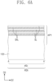
- FIGS. 5 , 7 , 9 , 11 , and 13 illustrate plan views of stages in a method of fabricating a semiconductor device according to some example embodiments.
- FIGS. 6 A, 8 A, 10 A, 12 A, and 14 A illustrate cross-sectional views taken along line A-A′ of FIGS. 5 , 7 , 9 , 11 , and 13 , respectively.
- FIGS. 6 B, 8 B, 10 B, 12 B, and 14 B illustrate cross-sectional views taken along line B-B′ of FIGS. 5 , 7 , 9 , 11 , and 13 , respectively.
- FIGS. 6 C, 8 C, 10 C, 12 C, and 14 C illustrate cross-sectional views taken along line C-C′ of FIGS. 5 , 7 , 9 , 11 , and 13 , respectively.
- FIGS. 6 D, 8 D, 10 D, 12 D, and 14 D illustrate cross-sectional views taken along line D-D′ of FIGS. 5 , 7 , 9 , 11 , and 13 , respectively.
- FIGS. 10 E, 12 E, and 14 E illustrate cross-sectional views taken along line E-E′ of FIGS. 9 , 11 , and 13 , respectively.
- FIGS. 10 F, 12 F, and 14 F illustrate cross-sectional views taken along line F-F′ of FIGS. 9 , 11 , and 13 , respectively.
- FIGS. 15 and 16 illustrate enlarged cross-sectional views of section M of FIG. 2 A , showing a semiconductor device according to some example embodiments.
- FIG. 1 illustrates a plan view of a semiconductor device according to some example embodiments.
- FIGS. 2 A, 2 B, 2 C, 2 D, 2 E, 2 F, 2 G, and 2 H illustrate cross-sectional views respectively taken along lines A-A′, B-B′, C-C′, D-D′, E-E′, F-F′, G-G′, and H-H′ of FIG. 1 .
- a substrate 100 may be provided that includes a peripheral region PER and a logic cell region LGC.
- the substrate 100 may be a compound semiconductor substrate or a semiconductor substrate including silicon, germanium, or silicon-germanium. In an implementation, the substrate 100 may be a silicon substrate.
- the peripheral region PER may be an area including transistors that constitute either a process core or an input/out terminal.
- the logic cell region LGC may be an area including a standard cell that constitutes a logic circuit.
- the peripheral region PER may include a long-gate transistor whose gate length (or channel length) is relatively large. A transistor on the peripheral region PER may operate at higher power than that required for operating a transistor on the logic cell region LGC. A transistor on the peripheral region PER will be first described in detail with reference to FIGS. 1 and 2 A to 2 D .
- the peripheral region PER may include a first PMOSFET region PR 1 and a first NMOSFET region NR 1 .
- the first PMOSFET region PR 1 and the first NMOSFET region NR 1 may be defined by a second trench TR 2 on or in an upper portion of the substrate 100 .
- the second trench TR 2 may be between the first PMOSFET region PR 1 and the first NMOSFET region NR 1 .
- the first PMOSFET region PR 1 and the first NMOSFET region NR 1 may be spaced apart from each other in a first direction D 1 across the second trench TR 2 .
- a first trench TR 1 on the upper portion of the substrate 100 may define a first active pattern AP 1 and a second active pattern AP 2 .
- the first active pattern AP 1 and the second active pattern AP 2 may be respectively on the first PMOSFET region PR 1 and the first NMOSFET region NR 1 .
- the first trench TR 1 may be shallower than the second trench TR 2 .
- the first and second active patterns AP 1 and AP 2 may extend in a second direction D 2 .
- the first and second active patterns AP 1 and AP 2 may be vertically protruding portions of the substrate 100 .
- a device isolation layer ST may fill the first and second trenches TR 1 and TR 2 .
- the device isolation layer ST may include a silicon oxide layer.
- the first and second active patterns AP 1 and AP 2 may have upper portions that vertically protrude upwardly from the device isolation layer ST (see FIG. 2 C ).
- the device isolation layer ST may cover none of the upper portions of the first and second active patterns AP 1 and AP 2 .
- the device isolation layer ST may cover lower sidewalls of the first and second active patterns AP 1 and AP 2 .
- the first active pattern AP 1 may include a first channel pattern CH 1 on the upper portion thereof.
- the second active pattern AP 2 may include a second channel pattern CH 2 on the upper portion thereof.
- Each of the first and second channel patterns CH 1 and CH 2 may include a first semiconductor pattern SP 1 , a second semiconductor pattern SP 2 , and a third semiconductor pattern SP 3 that are sequentially stacked.
- the first, second, and third semiconductor patterns SP 1 , SP 2 , and SP 3 may be spaced apart from each other in a vertical direction, e.g., a third direction D 3 .
- Each of the first, second, and third semiconductor patterns SP 1 , SP 2 , and SP 3 may include silicon (Si), germanium (Ge), or silicon-germanium (SiGe).
- each of the first, second, and third semiconductor patterns SP 1 , SP 2 , and SP 3 may include crystalline silicon.
- the term “or” is not an exclusive term, e.g., “A or B” would include A, B, or A and B
- a pair of first source/drain patterns SD 1 may be on the upper portion of the first active pattern AP 1 .
- the first source/drain patterns SD 1 may be impurity regions having a first conductivity type (e.g., p-type).
- the first, second, and third semiconductor patterns SP 1 , SP 2 , and SP 3 of the first channel pattern CH 1 may be between the pair of first source/drain patterns SD 1 .
- the first, second, and third semiconductor patterns SP 1 , SP 2 , and SP 3 of the first channel pattern CH 1 may connect the pair of first source/drain patterns SD 1 to each other.
- a pair of second source/drain patterns SD 2 may be on the upper portion of the second active pattern AP 2 .
- the second source/drain patterns SD 2 may be impurity regions having a second conductivity type (e.g., n-type).
- the first, second, and third semiconductor patterns SP 1 , SP 2 , and SP 3 of the second channel pattern CH 2 may be between the pair of second source/drain patterns SD 2 .
- the first, second, and third semiconductor patterns SP 1 , SP 2 , and SP 3 of the second channel pattern CH 2 may connect the pair of second source/drain patterns SD 2 to each other.
- the first and second source/drain patterns SD 1 and SD 2 may be epitaxial patterns formed by a selective epitaxial growth process.
- the first and second source/drain patterns SD 1 and SD 2 may have top surfaces at a level substantially the same as that of a top surface of the third semiconductor pattern SP 3 .
- one or more of the first and second source/drain patterns SD 1 and SD 2 may have a top surface higher than that of the third semiconductor pattern SP 3 adjacent thereto.
- the first source/drain patterns SD 1 may include a semiconductor element (e.g., SiGe) whose lattice constant is greater than that of a semiconductor element of the substrate 100 . Therefore, the first source/drain patterns SD 1 may provide the first channel pattern CH 1 with compressive stress.
- a semiconductor element e.g., SiGe
- the second source/drain patterns SD 2 may include the same semiconductor element (e.g., Si) as that of the substrate 100 .
- the second source/drain patterns SD 2 may include not only silicon (Si) but also carbon (C).
- the second source/drain patterns SD 2 may include silicon carbide (SiC).
- the second source/drain pattern SD 2 when the second source/drain pattern SD 2 includes silicon carbide (SiC), the second source/drain pattern SD 2 may have a carbon concentration of about 10 at % to about 30 at %.
- a pair of second source/drain patterns SD 2 including silicon carbide (SiC) may provide the second channel pattern CH 2 therebetween with tensile stress.
- a first gate electrode GE 1 may extend (e.g., lengthwise) in the first direction D 1 , while running across the first and second active patterns AP 1 and AP 2 .
- the first gate electrode GE 1 may extend from the first PMOSFET region PR 1 toward the first NMOSFET region NR 1 .
- the first gate electrode GE 1 may vertically overlap the first and second channel patterns CH 1 and CH 2 .
- the first gate electrode GE 1 may include a first part P 01 between the substrate 100 and the first semiconductor pattern SP 1 , a second part P 02 between the first semiconductor pattern SP 1 and the second semiconductor pattern SP 2 , a third part P 03 between the second semiconductor pattern SP 2 and the third semiconductor pattern SP 3 , and a fourth part P 04 on the third semiconductor pattern SP 3 .
- the first gate electrode GE 1 may be on a top surface TOS, a bottom surface BOS, and opposite sidewalls SIW of each of the first, second, and third semiconductor patterns SP 1 , SP 2 , and SP 3 .
- a transistor on the peripheral region PER may be a three-dimensional field effect transistor (e.g., MBCFET or GAAFET) in which a gate electrode surrounds a channel three-dimensionally.
- a pair of gate spacers GS may be on opposite sidewalls of the first gate electrode GE 1 .
- the gate spacers GS may extend (e.g., lengthwise) in the first direction D 1 along the first gate electrode GE 1 .
- the gate spacers GS may have top surfaces higher than (e.g., farther from the substrate 100 in the third direction D 3 than) that of the first gate electrode GE 1 .
- the top surfaces of the gate spacers GS may be coplanar with that of a first interlayer dielectric layer 110 which will be discussed below.
- the gate spacers GS may include SiCN, SiCON, or SiN.
- the gate spacers GS may each include a multi-layer formed of at least two of SiCN, SiCON, and SiN.
- a gate capping pattern GP may be on the first gate electrode GE 1 .
- the gate capping pattern GP may extend (e.g., lengthwise) in the first direction D 1 along the first gate electrode GE 1 .
- the gate capping pattern GP may include a material having an etch selectivity with respect to first and second interlayer dielectric layers 110 and 120 which will be discussed below.
- the gate capping pattern GP may include SiON, SiCN, SiCON, or SiN.
- a first gate dielectric layer GI 1 may be between the first gate electrode GE 1 and the first channel pattern CH 1 and between the first gate electrode GE 1 and the second channel pattern CH 2 .
- the first gate dielectric layer GI 1 may directly cover the top surface TOS, the bottom surface BOS, and the opposite sidewalls SIW of each of the first, second, and third semiconductor patterns SP 1 , SP 2 , and SP 3 .
- the first gate dielectric layer GI 1 may extend along a bottom surface of the first gate electrode GE 1 above the first gate dielectric layer GI 1 .
- the first gate dielectric layer GI 1 may cover a top surface of the device isolation layer ST below the first gate electrode GE 1 .
- the first gate dielectric layer GI 1 may include a silicon oxide layer, a silicon oxynitride layer, or a high-k dielectric layer.
- the high-k dielectric layer may include a material whose dielectric constant is greater than that of a silicon oxide layer.
- the high-k dielectric material may include hafnium oxide, hafnium silicon oxide, hafnium zirconium oxide, hafnium tantalum oxide, lanthanum oxide, zirconium oxide, zirconium silicon oxide, tantalum oxide, titanium oxide, barium strontium titanium oxide, barium titanium oxide, strontium titanium oxide, lithium oxide, aluminum oxide, lead scandium tantalum oxide, or lead zinc niobate.
- a semiconductor device may include a negative capacitance field effect transistor that uses a negative capacitor.
- the first gate dielectric layer GI 1 may include a ferroelectric material layer having ferroelectric properties and a paraelectric material layer having paraelectric properties.
- the ferroelectric material layer may have a negative capacitance, and the paraelectric material layer may have a positive capacitance.
- an overall capacitance when two or more capacitors are connected in series, and when each capacitor has a positive capacitance, an overall capacitance may be reduced to be less than the capacitance of each capacitor.
- an overall capacitance when at least one of two or more capacitors connected in series has a negative capacitance, an overall capacitance may have a positive value that is increased to be greater than an absolute value of the capacitance of each capacitor.
- the ferroelectric material layer having a negative capacitance When the ferroelectric material layer having a negative capacitance is connected in series to the paraelectric material layer having a positive capacitance, there may be an increase in overall capacitance of the ferroelectric and paraelectric material layers that are connected in series.
- the increase in overall capacitance may be used to allow a transistor including the ferroelectric material layer to have a subthreshold swing of less than about 60 mV/decade at room temperature.
- the ferroelectric material layer may have ferroelectric properties.
- the ferroelectric material layer may include, e.g., hafnium oxide, hafnium zirconium oxide, barium strontium titanium oxide, or lead zirconium titanium oxide.
- the hafnium zirconium oxide may be a material in which hafnium oxide is doped with zirconium (Zr).
- the hafnium zirconium oxide may be a compound of hafnium (Hf), zirconium (Zr), and oxygen (O).
- the ferroelectric material layer may further include impurities doped thereinto.
- the impurities may include aluminum (Al), titanium (Ti), niobium (Nb), lanthanum (La), yttrium (Y), magnesium (Mg), silicon (Si), calcium (Ca), cerium (Ce), dysprosium (Dy), erbium (Er), gadolinium (Gd), germanium (Ge), scandium (Sc), strontium (Sr), or tin (Sn).
- a kind of impurities included in the ferroelectric material layer may be changed depending on what ferroelectric material is included in the ferroelectric material layer.
- the ferroelectric material layer may include an impurity, e.g., gadolinium (Gd), silicon (Si), zirconium (Zr), aluminum (Al), or yttrium (Y).
- an impurity e.g., gadolinium (Gd), silicon (Si), zirconium (Zr), aluminum (Al), or yttrium (Y).
- the ferroelectric material layer may include about 3 to 8 at % aluminum.
- the at % of impurities may be a percent of atoms of impurity (e.g., aluminum) to the sum of atoms of hafnium and the impurity (e.g., aluminum).
- the ferroelectric material layer may include about 2 to 10 at % silicon.
- the ferroelectric material layer may include about 2 to 10 at % yttrium.
- the ferroelectric material layer may include about 1 to 7 at % gadolinium.
- the ferroelectric material layer may include about 50 to 80 at % zirconium.
- the paraelectric material layer may have paraelectric properties.
- the paraelectric material layer may include, e.g., silicon oxide or a high-k metal oxide.
- the metal oxide included in the paraelectric material layer may include, e.g., hafnium oxide, zirconium oxide, or aluminum oxide.
- the ferroelectric and paraelectric material layers may include the same material.
- the ferroelectric material layer may have ferroelectric properties, and the paraelectric material layer may not have ferroelectric properties.
- the ferroelectric material layer and the paraelectric material layer include hafnium oxide, the hafnium oxide included in the ferroelectric material layer may have a different crystal structure from that of the hafnium oxide included in the paraelectric material layer.
- the ferroelectric material layer may have a thickness having ferroelectric properties.
- the thickness of the ferroelectric material layer may range, e.g., from about 0.5 nm to about 10 nm.
- Ferroelectric materials have their own critical thickness that exhibits ferroelectric properties, and the thickness of the ferroelectric material layer may depend on ferroelectric material.
- the first gate dielectric layer GI 1 may include one ferroelectric material layer. In an implementation, the first gate dielectric layer GI 1 may include a plurality of ferroelectric material layers that are spaced apart from each other. In an implementation, the first gate dielectric layer GI 1 may have a stack-layered structure in which a plurality of ferroelectric material layers are stacked alternately with a plurality of paraelectric material layers.
- the first gate electrode GE 1 may include a first metal pattern and a second metal pattern on the first metal pattern.
- the first gate dielectric layer GI 1 may include the first metal pattern adjacent to the first and second channel patterns CH 1 and CH 2 .
- the first metal pattern may include a work-function metal that helps control a threshold voltage of a transistor. A thickness and composition of the first metal pattern may be adjusted to achieve a desired threshold voltage of a transistor.
- the first metal pattern may include a metal nitride layer.
- the first metal pattern may include nitrogen (N) and, e.g., titanium (Ti), tantalum (Ta), aluminum (Al), tungsten (W), or molybdenum (Mo).
- the first metal pattern may further include carbon (C).
- the first metal pattern may include a plurality of stacked work-function metal layers.
- the second metal pattern may include metal whose resistance is less than that of the first metal pattern.
- the second metal pattern may include tungsten (W), aluminum (Al), titanium (Ti), or tantalum (Ta).
- inner spacers IP may be on the first NMOSFET region NR 1 .
- the inner spacers IP may be correspondingly between the second source/drain pattern SD 2 and the first, second, and third parts P 01 , P 02 , and P 03 of the first gate electrode GE 1 .
- the inner spacers IP may be in direct contact with the second source/drain pattern SD 2 .
- the inner spacer IP may space each of the first, second, and third parts P 01 , P 02 , and P 03 of the first gate electrode GE 1 apart from the second source/drain pattern SD 2 .
- the inner spacer IP may include a low-k dielectric material.
- the low-k dielectric material may include a material whose dielectric constant is less than that of silicon oxide or silicon nitride.
- the low-k dielectric material may include silicon oxide, silicon oxide doped with fluorine or carbon, porous silicon oxide, or an organic polymeric dielectric.
- a first interlayer dielectric layer 110 may be on the substrate 100 .
- the first interlayer dielectric layer 110 may cover the gate spacers GS and the first and second source/drain patterns SD 1 and SD 2 .
- the first interlayer dielectric layer 110 may have a top surface (e.g., surface facing away from the substrate 100 in the third direction D 3 ) that is substantially coplanar with that of the gate capping pattern GP and those of the gate spacers GS.
- the first interlayer dielectric layer 110 may include a second interlayer dielectric layer 120 thereon that covers the gate capping pattern GP.
- the first and second interlayer dielectric layers 110 and 120 may include a silicon oxide layer.
- Active contacts AC may penetrate the first and second interlayer dielectric layers 110 and 120 and may correspondingly have an electrical connection with the first and second source/drain patterns SD 1 and SD 2 .
- a pair of active contacts AC may be on opposite sides of the first gate electrode GE 1 . When viewed in a plan view, the active contact AC may have a bar shape that extends in the first direction D 1 .
- the active contact AC may include a conductive pattern FM and a barrier pattern BM that surrounds the conductive pattern FM.
- the conductive pattern FM may include a metal, e.g., aluminum, copper, tungsten, molybdenum, or cobalt.
- the barrier pattern BM may cover sidewalls and a bottom surface of the conductive pattern FM.
- the barrier pattern BM may include a metal layer and a metal nitride layer.
- the metal layer may include titanium, tantalum, tungsten, nickel, cobalt, or platinum.
- the metal nitride layer may include a titanium nitride (TiN) layer, a tantalum nitride (TaN) layer, a tungsten nitride (WN) layer, a nickel nitride (NiN) layer, a cobalt nitride (CoN) layer, or a platinum nitride (PtN) layer.
- TiN titanium nitride
- TaN tantalum nitride
- WN tungsten nitride
- NiN nickel nitride
- CoN cobalt nitride
- PtN platinum nitride
- the active contact AC may be a self-aligned contact.
- the gate capping pattern GP and the gate spacer GS may be used to form the active contact AC in a self-aligned manner.
- the active contact AC may cover at least a portion of a sidewall of the gate spacer GS.
- the active contact AC may partially cover a portion of the top surface of the gate capping pattern GP.
- a silicide pattern SC may be between the active contact AC and the first source/drain pattern SD 1 and between the active contact AC and the second source/drain pattern SD 2 .
- the active contact AC may be electrically connected through the silicide pattern SC to one of the first and second source/drain patterns SD 1 and SD 2 .
- the silicide pattern SC may include a metal silicide, e.g., titanium silicide, tantalum silicide, tungsten silicide, nickel silicide, or cobalt silicide.
- a gate contact GC may penetrate the second interlayer dielectric layer 120 and the gate capping pattern GP and to have an electrical connection with the first gate electrode GE 1 .
- the gate contact GC may be on the device isolation layer ST between the first PMOSFET region PR 1 and the first NMOSFET region NR 1 .
- the gate contact GC may have a bar shape that extends (e.g., lengthwise) in the second direction D 2 .
- the gate contact GC may include a conductive pattern FM and a barrier pattern BM that surrounds the conductive pattern FM.
- a third interlayer dielectric layer 130 may be on the second interlayer dielectric layer 120 .
- a first metal layer M 1 may be in the third interlayer dielectric layer 130 .
- the first metal layer M 1 may include first lines IL 1 and first vias VI 1 .
- the first vias VI 1 may be below the first lines IL 1 .
- the first lines IL 1 may be along the first direction D 1 .
- Each of the first lines IL 1 may have a linear or bar shape that extends in the second direction D 2 .
- the first vias VI 1 may be correspondingly below the first lines IL 1 of the first metal layer M 1 .
- the first vias VI 1 may be correspondingly between the active contacts AC and the first lines IL 1 .
- the first vias VI 1 may be correspondingly between the gate contacts GC and the first lines IL 1 .
- the first line IL 1 and its underlying first via VI 1 of the first metal layer M 1 may be formed by separate processes from each other.
- each of the first line IL 1 and the first via VI 1 may be formed by a single damascene process.
- a sub-20 nm process may be employed to fabricate a semiconductor device according to some example embodiments.
- a fourth interlayer dielectric layer 140 may be on the third interlayer dielectric layer 130 .
- a second metal layer M 2 may be in the fourth interlayer dielectric layer 140 .
- the second metal layer M 2 may include second lines IL 2 .
- Each of the second lines IL 2 may have a linear or bar shape that extends in the first direction D 1 .
- the second lines IL 2 may extend in the second direction D 2 .
- the second metal layer M 2 may further include second vias VI 2 .
- the second vias VI 2 may be correspondingly below the second lines IL 2 .
- the second vias VI 2 may be correspondingly between the first line IL 1 and the second lines IL 2 .
- the second line IL 2 and its underlying second via VI 2 may be formed as a single piece in the same process.
- a dual damascene process may be employed to simultaneously form the second line IL 2 and the second via VI 2 of the second metal layer M 2 .
- the first lines IL 1 of the first metal layer M 1 may include a conductive material the same as or different from that of the second lines IL 2 of the second metal layer M 2 .
- the first and second lines IL 1 and IL 2 may include a metal, e.g., copper (Cu), ruthenium (Rh), cobalt (Co), tungsten (W), aluminum (Al), or molybdenum (Mo).
- additional metal layers may be stacked on the fourth interlayer dielectric layer 140 .
- Each of the stacked metal layers may include routing lines.
- a transistor on the logic cell region LGC will be described in detail below with reference to FIGS. 1 and 2 E to 2 H . Omission may be made to avoid repetitive descriptions of technical features the same as or similar to those of the transistor on the peripheral region PER discussed with reference to FIGS. 1 and 2 A to 2 D , and differences thereof will be discussed in detail.
- the logic cell region LGC may include a second PMOSFET region PR 2 and a second NMOSFET region NR 2 .
- the second PMOSFET region PR 2 and the second NMOSFET region NR 2 may be defined by a fourth trench TR 4 on the upper portion of the substrate 100 .
- a third active pattern AP 3 and a fourth active pattern AP 4 may be defined by a third trench TR 3 formed on the upper portion of the substrate 100 .
- the third active pattern AP 3 and the fourth active pattern AP 4 may be respectively on the second PMOSFET region PR 2 and the second NMOSFET region NR 2 .
- the third active pattern AP 3 may include a third channel pattern CH 3 on an upper portion thereof, and the fourth active pattern AP 4 may include a fourth channel pattern CH 4 on an upper portion thereof.
- Each of the third and fourth channel patterns CH 3 and CH 4 may include first, second, and third semiconductor patterns SP 1 , SP 2 , and SP 3 that are sequentially stacked.
- the first, second, and third semiconductor patterns SP 1 , SP 2 , and SP 3 of the third and fourth channel patterns CH 3 and CH 4 may be shorter than the first, second, and third semiconductor patterns SP 1 , SP 2 , and SP 3 of the first and second channel patterns CH 1 and CH 2 discussed above.
- each of the first, second, and third semiconductor patterns SP 1 , SP 2 , and SP 3 of the third and fourth channel patterns CH 3 and CH 4 may have a length in the second direction D 2 less than a length in the second direction D 2 of each of the first, second, and third semiconductor patterns SP 1 , SP 2 , and SP 3 of the first and second channel patterns CH 1 and CH 2 .
- the logic cell region LGC may include a short-gate transistor whose gate length (or channel length) is relatively small.
- Third source/drain patterns SD 3 may be on the upper portion of the third active pattern AP 3 .
- Fourth source/drain patterns SD 4 may be on the upper portion of the fourth active pattern AP 4 .
- the first, second, and third semiconductor patterns SP 1 , SP 2 , and SP 3 of the third channel pattern CH 3 may be between a pair of third source/drain patterns SD 3 .
- the first, second, and third semiconductor patterns SP 1 , SP 2 , and SP 3 of the fourth channel pattern CH 4 may be between a pair of fourth source/drain patterns SD 4 .
- Each of the third source/drain patterns SD 3 may be an epitaxial pattern that contains impurities having a first conductivity type (e.g., p-type).
- Each of the fourth source/drain patterns SD 4 may be an epitaxial pattern that contains impurities having a second conductivity type (e.g., n-type).
- Second gate electrodes GE 2 may extend in the first direction D 1 , while running across the third and fourth channel patterns CH 3 and CH 4 .
- the second gate electrode GE 2 may extend from the second PMOSFET region PR 2 toward the second NMOSFET region NR 2 .
- the second gate electrode GE 2 may vertically overlap the third and fourth channel patterns CH 3 and CH 4 .
- a pair of gate spacers GS may be on opposite sidewalls of the second gate electrode GE 2 .
- a gate capping pattern GP may be on the second gate electrode GE 2 .
- the second gate electrode GE 2 may be on a top surface, a bottom surface, and opposite sidewalls of each of the first, second, and third semiconductor patterns SP 1 , SP 2 , and SP 3 .
- a transistor on the logic cell region LGC may be a three-dimensional field effect transistor (e.g., MBCFET or GAAFET) in which a gate electrode surrounds a channel three-dimensionally.
- a second gate dielectric layer GI 2 may be between the second gate electrode GE 2 and the third channel pattern CH 3 and between the second gate electrode GE 2 and the fourth channel pattern CH 4 .
- the second gate dielectric layer GI 2 may include aa silicon oxide layer, a silicon nitride layer, or a high-k dielectric layer.
- the second gate dielectric layer GI 2 on the logic cell region LGC may have a thickness less than that of the first gate dielectric layer GI 1 on the peripheral region PER.
- the second NMOSFET region NR 2 may include inner spacers IP thereon.
- the inner spacers IP may be correspondingly between the fourth source/drain pattern SD 4 and first, second, and third parts P 01 , P 02 , and P 03 of the second gate electrode GE 2 .
- the inner spacers IP may be omitted from the second PMOSFET region PR 2 .
- a first interlayer dielectric layer 110 and a second interlayer dielectric layer 120 may be on an entire surface of the substrate 100 .
- Active contacts AC may penetrate the first and second interlayer dielectric layers 110 and 120 and may be connected with the third and fourth source/drain patterns SD 3 and SD 4 .
- a gate contact GC may penetrate the second interlayer dielectric layer 120 and the gate capping pattern GP and may be electrically connected with the second gate electrode GE 2 .
- a first metal layer M 1 and a second metal layer M 2 may be on the second interlayer dielectric layer 120 .
- the detailed descriptions of the active contacts AC, the gate contact GC, the first metal layer M 1 , and the second metal layer M 2 may be substantially the same as those discussed with reference to FIGS. 1 and 2 A to 2 D .
- FIG. 3 illustrates an enlarged cross-sectional view of section M of FIG. 2 A .
- At least one of the first, second, and third semiconductor patterns SP 1 , SP 2 , and SP 3 may be bent (e.g., curved).
- at least two selected of the first, second, and third semiconductor patterns SP 1 , SP 2 , and SP 3 may be bent.
- the at least one or two semiconductor patterns may be bent in the third direction D 3 (e.g., in a vertical direction away from a bottom surface of the substrate 100 ) or in a direction opposite to the third direction D 3 (e.g., in a vertical direction approaching the bottom surface of the substrate 100 ).
- the at least one or two semiconductor patterns may be curved such that a concave opening therein is open toward the substrate 100 in the third direction D 3 . In an implementation, the at least one or two semiconductor patterns may be curved such that a concave opening therein is open away from the substrate 100 in the third direction D 3 .
- the third semiconductor pattern SP 3 may be bent in a direction opposite to the third direction D 3 (e.g., away from the substrate 100 ). In an implementation, the third semiconductor pattern SP 3 may be bent toward the second semiconductor pattern SP 2 . In an implementation, the third semiconductor pattern SP 3 may have one or both of a curved bottom surface and a curved top surface.
- a first height difference HC 1 may indicate the degree of bending of the third semiconductor pattern SP 3 .
- the first height difference HC 1 may be a difference in height (in the third direction D 3 ) between a center point CEP and an edge point EDP at the bottom (or top) surface of the third semiconductor pattern SP 3 .
- the edge point EDP at the bottom surface of the third semiconductor pattern SP 3 may be in contact with the first source/drain pattern SD 1 .
- the edge point EDP at the bottom surface of the third semiconductor pattern SP 3 may be in contact with a corner of the first gate dielectric layer GI 1 .
- the center point CEP at the bottom surface of the third semiconductor pattern SP 3 may be at a first level LV 1
- the edge point EDP at the bottom surface of the third semiconductor pattern SP 3 may be at a second level LV 2
- the first height difference HC 1 may be a difference or distance between the first level LV 1 and the second level LV 2 , or LV 1 -LV 2 .
- the second level LV 2 may be higher than the first level LV 1
- the first height difference HC 1 may have a negative value.
- the second semiconductor pattern SP 2 may be bent in the third direction D 3 .
- the second semiconductor pattern SP 2 may be bent toward the third semiconductor pattern SP 3 .
- the second semiconductor pattern SP 2 may have one or both of a curved bottom surface and a curved top surface.
- a second height difference HC 2 may indicate the degree of bending of the second semiconductor pattern SP 2 .
- the second height difference HC 2 may be a difference in height (in the third direction D 3 ) between a center point CEP and an edge point EDP at the bottom (or top) surface of the second semiconductor pattern SP 2 .
- the center point CEP at the bottom surface of the second semiconductor pattern SP 2 may be at a third level LV 3
- the edge point EDP at the bottom surface of the second semiconductor pattern SP 2 may be at a fourth level LV 4 .
- the second height difference HC 2 may be a difference or distance between the third level LV 3 and the fourth level LV 4 , or LV 3 -LV 4 .
- the third level LV 3 may be higher than the fourth level LV 4 , and the second height difference HC 2 may have a positive value.
- the second and third semiconductor patterns SP 2 and SP 3 may be bent toward each other or away from each other.
- the first height difference HC 1 may have a negative value and the second height difference HC 2 may have a positive value, e.g., the third semiconductor pattern SP 3 may be curved away from the second semiconductor pattern SP 2 and vice versa, as illustrated in FIG. 3 .
- the first semiconductor pattern SP 1 may not be bent or curved, and may instead be flat. In an implementation, the first semiconductor pattern SP 1 may have one or both of a flat bottom surface and a flat top surface. The degree of bending of the first semiconductor pattern SP 1 may be zero or almost zero. There may be no difference in height between the center point CEP and the edge point EDP at the bottom (or top) surface of the first semiconductor pattern SP 1 .
- the degree of bending of the semiconductor pattern SP 1 , SP 2 , or SP 3 may be defined to refer to a difference in height between the center point CEP and the edge point EDP of the semiconductor pattern SP 1 , SP 2 , or SP 3 .
- the degree of bending (or the height difference) of the semiconductor pattern SP 1 , SP 2 , or SP 3 has a positive value, it may be determined that the semiconductor pattern SP 1 , SP 2 , or SP 3 is bent in the third direction D 3 .
- the degree of bending (or the height difference) of the semiconductor pattern SP 1 , SP 2 , or SP 3 has a negative value, it may be determined that the semiconductor pattern SP 1 , SP 2 , or SP 3 is bent in a direction opposite to the third direction D 3 .
- a ratio of the bending degree to a thickness TK of the semiconductor pattern SP 1 , SP 2 , or SP 3 is in a range of about 0.1 to about 2, e.g., about 0.3 to about 2, it may be defined that the semiconductor pattern SP 1 , SP 2 , or SP 3 is bent.
- the ratio of the bending degree to the thickness TK of the semiconductor pattern SP 1 , SP 2 , or SP 3 is in a range of less than about 0.1, it may be defined that the semiconductor pattern SP 1 , SP 2 , or SP 3 is flat.
- the first part P 01 of the first gate electrode GE 1 may have a thickness T 1 (e.g., in the third direction D 3 ) that is not changed, e.g., and is constant from the center point CEP of the first semiconductor pattern SP 1 to the edge point EDP thereof.
- the thickness T 1 of the first part P 01 may be substantially constant from its center point to its edge point.
- the second part P 02 of the first gate electrode GE 1 may have a thickness T 2 that decreases from the center point CEP of the second semiconductor pattern SP 2 to the edge point EDP.
- the thickness T 2 of the second part P 02 may decrease from its center point to its edge point.
- the third part P 03 of the first gate electrode GE 1 may have a thickness T 3 that increases from the center point CEP of the third semiconductor pattern SP 3 to the edge point EDP thereof.
- the thickness T 3 of the third part P 03 may increase from its center point to its edge point.
- the thickness T 1 at the center point of the first part P 01 may be greater than the thickness T 3 at the center point of the third part P 03 .
- the thickness T 2 at the center point of the second part P 02 may be greater than the thickness T 1 at the center point of the first part P 01 .
- the second part P 02 may have a volume or cross sectional area greater than that of either other of the first and third parts P 01 and P 03 .
- the fourth part P 04 of the first gate electrode GE 1 may have a curved bottom surface.
- a third height difference HC 3 may indicate the degree of bending or curvature at the bottom surface of the fourth part P 04 .
- the third height difference HC 3 may be a difference in height between a center point CEP at the bottom surface of the fourth part P 04 and an edge point EDP at the bottom surface of the fourth part P 04 .
- the center point CEP at the bottom surface of the fourth part P 04 may be at a fifth level LV 5
- the edge point EDP at the bottom surface of the fourth part P 04 may be at a sixth level LV 6 .
- the third height difference HC 3 may be a difference between the fifth level LV 5 and the sixth level LV 6 , or LV 5 -LV 6 .
- the sixth level LV 6 may be higher than the fifth level LV 5 , and thus the third height difference HC 3 may have a negative value.
- the bottom surface of the fourth part P 04 may be bent in a direction opposite to the third direction D 3 (e.g., the bottom surface of the fourth part P 04 may have a convex shape protruding toward the substrate 100 in the third direction D 3 ).
- FIG. 4 illustrates an enlarged cross-sectional view of section N of FIG. 2 B .
- At least one of the first, second, and third semiconductor patterns SP 1 , SP 2 , and SP 3 may be bent or curved.
- at least two of the first, second, and third semiconductor patterns SP 1 , SP 2 , and SP 3 may be bent.
- the at least one or two semiconductor patterns may be bent in the third direction D 3 or in a direction opposite to the third direction D 3 .
- the third semiconductor pattern SP 3 may be bent in the third direction D 3 .
- the third semiconductor pattern SP 3 may be bent in a direction away from the second semiconductor pattern SP 2 (e.g., may have a convex surface protruding away from the second semiconductor pattern SP 2 in the third direction D 3 ).
- the third semiconductor pattern SP 3 may have one or both of a curved bottom surface and a curved top surface.
- a fourth height difference HC 4 may indicate the degree of bending of the third semiconductor pattern SP 3 .
- the center point CEP at the bottom surface of the third semiconductor pattern SP 3 may be at a seventh level LV 7
- the edge point EDP at the bottom surface of the third semiconductor pattern SP 3 may be at an eighth level LV 8 .
- the fourth height difference HC 4 may be a difference between the seventh level LV 7 and the eighth level LV 8 , or LV 7 -LV 8 .
- the seventh level LV 7 may be higher than the eighth level LV 8
- the fourth height difference HC 4 may have a positive value.
- the second semiconductor pattern SP 2 may be bent in a direction opposite to the bending direction of the third direction D 3 .
- the second semiconductor pattern SP 2 may be bent (e.g., to have a convex curved shape protruding) toward the first semiconductor pattern SP 1 .
- the second semiconductor pattern SP 2 may have one or both of a curved bottom surface and a curved top surface.
- a fifth height difference HC 5 may indicate the degree of bending of the second semiconductor pattern SP 2 .
- the center point CEP at the bottom surface of the second semiconductor pattern SP 2 may be at a ninth level LV 9
- the edge point EDP at the bottom surface of the second semiconductor pattern SP 2 may be at a tenth level LV 10 .
- the fifth height difference HC 5 may be a difference between the ninth level LV 9 and the tenth level LV 10 , or LV 9 -LV 10 .
- the tenth level LV 10 may be higher than the ninth level LV 9
- the fifth height difference HC 5 may have a negative value.
- the second and third semiconductor patterns SP 2 and SP 3 may be bent away from (e.g., in opposite directions relative to) each other.
- the first semiconductor pattern SP 1 may not be bent, and may be flat.
- the first part P 01 of the first gate electrode GE 1 may have a thickness T 4 that is not changed, e.g., that is constant across its length, from the center point CEP of the first semiconductor pattern SP 1 to the edge point EDP thereof.
- the second part P 02 of the first gate electrode GE 1 may have a thickness T 5 that increases from the center point CEP of the second semiconductor pattern SP 2 to the edge point EDP thereof.
- the thickness T 5 of the second part P 02 may increase from its center point to its edge point.
- the third part P 03 of the first gate electrode GE 1 may have a thickness T 6 that decreases from the center point CEP of the third semiconductor pattern SP 3 to the edge point EDP thereof.
- the thickness T 6 of the third part P 03 may decrease from its center point to its edge point.
- the thickness T 4 at the center point of the first part P 01 may be greater than the thickness T 5 at the center point of the second part P 02 .
- the thickness T 6 at the center point of the third part P 03 may be greater than the thickness T 4 at the center point of the first part P 01 .
- the third part P 03 may have a volume or cross sectional area greater than that of any other of the first and second parts P 01 and P 02 .
- the fourth part P 04 of the first gate electrode GE 1 may have a curved bottom surface.
- a sixth height difference HC 6 may indicate the degree of bending or curvature at the bottom surface of the fourth part P 04 .
- the center point CEP at the bottom surface of the fourth part P 04 may be at an eleventh level LV 11
- the edge point EDP at the bottom surface of the fourth part P 04 may be at a twelfth level LV 12 .
- the sixth height difference HC 6 may be a difference between the eleventh level LV 11 and the twelfth level LV 12 .
- the eleventh level LV 11 may be higher than the twelfth level LV 12
- the sixth height difference HC 6 may have a positive value.
- the bottom surface of the fourth part P 04 may be bent in the third direction D 3 .
- bottom surface of the fourth part P 04 may be convex.
- an aspect of bending of a semiconductor pattern on the first PMOSFET region PR 1 may be different from an aspect of bending of a semiconductor pattern of the first NMOSFET region NR 1 .
- a semiconductor pattern of a long-gate transistor in accordance with some example embodiments may be bent in various ways, and the following will describe examples thereof.
- each of the first, second, and third semiconductor patterns SP 1 , SP 2 , and SP 3 that constitute a channel may be adjusted to its direction and degree of bending, and the first, second, and third parts P 01 , P 02 , and P 03 of the first gate electrode GE 1 may be controlled to have different volumes from each other. In an implementation, even when long-gate transistors have the same size, the transistors may be adjusted to have different driving forces.
- a long-gate PMOSFET of FIG. 3 may be adjusted such that the second part P 02 of the first gate electrode GE 1 has a volume greater than that of any other of the first and third parts P 01 and P 03 of the first gate electrode GE 1 .
- a long-gate NMOSFET of FIG. 4 may be adjusted such that the third part P 03 of the first gate electrode GE 1 has a volume greater than that of any other of the first and second parts P 01 and P 02 of the first gate electrode GE 1 .
- a variation in physical structure shown in FIG. 3 or 4 may generate the difference in driving force even if the PMOSFET and NMOSFET have the same size.
- FIGS. 5 , 7 , 9 , 11 , and 13 illustrate plan views of stages in a method of fabricating a semiconductor device according to some example embodiments.
- FIGS. 6 A, 8 A, 10 A, 12 A, and 14 A illustrate cross-sectional views taken along line A-A′ of FIGS. 5 , 7 , 9 , 11 , and 13 , respectively.
- FIGS. 6 B, 8 B, 10 B, 12 B, and 14 B illustrate cross-sectional views taken along line B-B′ of FIGS. 5 , 7 , 9 , 11 , and 13 , respectively.
- FIGS. 6 C, 8 C, 10 C, 12 C, and 14 C illustrate cross-sectional views taken along line C-C′ of FIGS.
- FIGS. 6 D, 8 D, 10 D, 12 D, and 14 D illustrate cross-sectional views taken along line D-D′ of FIGS. 5 , 7 , 9 , 11 , and 13 , respectively.
- FIGS. 10 E, 12 E, and 14 E illustrate cross-sectional views taken along line E-E′ of FIGS. 9 , 11 , and 13 , respectively.
- FIGS. 10 F, 12 F, and 14 F illustrate cross-sectional views taken along line F-F′ of FIGS. 9 , 11 , and 13 , respectively.
- a substrate 100 may be provided which includes a peripheral region PER and a logic cell region LGC.
- Semiconductor layers SL and sacrificial layers SAL may be formed alternately stacked on the substrate 100 .
- the semiconductor layers SL may include silicon (Si), germanium (Ge), or silicon-germanium (SiGe), and the sacrificial layers SAL may include another of silicon (Si), germanium (Ge), or silicon-germanium (SiGe).
- the semiconductor layers SL may include silicon (Si), and the sacrificial layers SAL may include silicon-germanium (SiGe).
- the substrate 100 may undergo a first patterning process to form a first trench TR 1 that defines first, second, third, and fourth active patterns AP 1 , AP 2 , AP 3 , and AP 4 .
- the semiconductor layers SL and the sacrificial layers SAL may be patterned during the first patterning process.
- each of the first to fourth active patterns AP 1 to AP 4 may include the semiconductor layers SL and the sacrificial layers SAL that are alternately stacked on the substrate 100 .
- the substrate 100 may undergo a second patterning process to form a second trench TR 2 that defines a first PMOSFET region PR 1 , a first NMOSFET region NR 1 , a second PMOSFET region PR 2 , and a second NMOSFET region NR 2 .
- the second trench TR 2 may be formed deeper than the first trench TR 1 . In an implementation, it is possible to omit the second patterning process for forming the second trench TR 2 .
- the first PMOSFET region PR 1 and the first NMOSFET region NR 1 may be on the peripheral region PER.
- a first active pattern AP 1 and a second active pattern AP 2 may be respectively formed on the first PMOSFET region PR 1 and the first NMOSFET region NR 1 .
- the second PMOSFET region PR 2 and the second NMOSFET region NR 2 may be on the logic cell region LGC.
- a third active pattern AP 3 and a fourth active pattern AP 4 may be respectively formed on the second PMOSFET region PR 2 and the second NMOSFET region NR 2 .
- a device isolation layer ST may be formed on the substrate 100 , filling the first and second trenches TR 1 and TR 2 .
- the device isolation layer ST may include a dielectric material, such as a silicon oxide layer.
- the device isolation layer ST may be recessed until upper portions of the first to fourth active patterns AP 1 to AP 4 are exposed. Thus, the upper portions of the first and second active patterns AP 1 and AP 2 may vertically protrude upwards from the device isolation layer ST.
- a first sacrificial pattern PP 1 may be formed to run across the first and second active patterns AP 1 and AP 2 .
- second sacrificial patterns PP 2 may be formed to run across the third and fourth active patterns AP 3 and AP 4 .
- the first sacrificial pattern PP 1 and the second sacrificial patterns PP 2 may be formed to have their linear or bar shapes that extend in a first direction D 1 .
- the first sacrificial pattern PP 1 may be formed to have a width greater than that of the second sacrificial pattern PP 2 .
- the formation of the first and second sacrificial patterns PP 1 and PP 2 may include forming a sacrificial layer on an entire surface of the substrate 100 , forming hardmask patterns MA on the sacrificial layer, and using the hardmask patterns MA as an etching mask to pattern the sacrificial layer.
- the sacrificial layer may include polysilicon.
- the patterning process for forming the first and second sacrificial patterns PP 1 and PP 2 may include a lithography process in which an extreme ultraviolet (EUV) radiation is used.
- EUV extreme ultraviolet
- the EUV may mean an ultraviolet ray having a wavelength of about 4 nm to about 124 nm, e.g., about 4 nm to about 20 nm, or about 13.5 nm.
- the EUV may denote light whose energy is in the range of about 6.21 eV to about 124 eV, e.g., about 90 eV to about 95 eV.
- the EUV lithography process may include exposure and development processes in which the EUV is irradiated onto a photoresist layer.
- the photoresist layer may be an organic photoresist that contains an organic polymer, e.g., polyhydroxystyrene.
- the organic photoresist may further include a photosensitive compound that is sensitive to the EUV.
- the organic photoresist may additionally include a material whose EUV absorption coefficient is high, e.g., an organometallic material, an iodine-containing material, or a fluorine-containing material.
- the photoresist layer may be an inorganic photoresist that contains an inorganic material, e.g., tin oxide.
- the photoresist layer may be formed to have a relatively small thickness.
- the photoresist layer exposed to the EUV may be developed to form photoresist patterns.
- the photoresist patterns when viewed in plan, may have a linear shape that extends in one direction, an island shape, a zigzag shape, a honeycomb shape, or a circular shape.
- the photoresist patterns may be used as an etching mask to pattern one or more mask layers that are stacked thereunder, and the hardmask patterns MP may be formed as discussed above.
- the hardmask patterns MP may be used as an etching mask to pattern a target layer or the sacrificial layer to form on a wafer a plurality of patterns or the first and second sacrificial patterns PP 1 and PP 2 .
- a multi-patterning technique may be required to use two or more photomasks so as to form fine-pitched patterns on a wafer.
- MPT multi-patterning technique
- even a single photomask may form the first and second sacrificial patterns PP 1 and PP 2 having fine pitches.
- a distance equal to or less than about 45 nm may be given as a minimum pitch between the first and second sacrificial patterns PP 1 and PP 2 that are formed by the EUV lithography according to the present embodiment.
- the EUV lithography may be performed to form the first and second sacrificial patterns PP 1 and PP 2 that are sophisticated and fine, even without the multi-patterning process.
- the EUV lithography process may be used to perform not only the patterning process for forming the first and second sacrificial patterns PP 1 and PP 2 , but also the patterning process for forming the first to fourth active patterns AP 1 to AP.
- a pair of gate spacers GS may be formed on opposite sidewalls of each of the first and second sacrificial patterns PP 1 and PP 2 .
- the formation of the gate spacers GS may include conformally forming a gate spacer layer on the entire surface of the substrate 100 and anisotropically etching the gate spacer layer.
- the gate spacer layer may include, e.g., SiCN, SiCON, or SiN.
- the gate spacer layer may be a multi-layer including at least two of SiCN, SiCON, and SiN.
- first to fourth source/drain patterns SD 1 to SD 4 may be respectively formed on the first to fourth active patterns AP 1 to AP 4 .
- the first source/drain patterns SD 1 may be formed on the upper portion of the first active pattern AP 1 .
- a pair of first source/drain patterns SD 1 may be formed on opposite sides of the first sacrificial pattern PP 1 .
- the hardmask patterns MA and the gate spacers GS may be used as an etching mask to etch the upper portion of the first active pattern AP 1 to form first recesses RS 1 .
- the device isolation layer ST may be recessed between the first active patterns AP 1 (see FIG. 10 C ).
- the first source/drain pattern SD 1 may be formed by performing a selective epitaxial growth process in which an inner wall of the first recess RS 1 of the first active pattern AP 1 is used as a seed layer.
- the formation of the first source/drain patterns SD 1 may define a first channel pattern CH 1 that includes first, second, and third semiconductor patterns SP 1 , SP 2 , and SP 3 between the pair of first source/drain patterns SD 1 .
- the selective epitaxial growth process may include a chemical vapor deposition (CVD) process or a molecular beam epitaxy (MBE) process.
- the first source/drain patterns SD 1 may include a semiconductor element (e.g., SiGe) whose lattice constant is greater than that of a semiconductor element of the substrate 100 .
- a semiconductor element e.g., SiGe
- Each of the first source/drain patterns SD 1 may be formed of a plurality of semiconductor layers.
- impurities may be in-situ implanted during the selective epitaxial growth process for the formation of the first source/drain patterns SD 1 .
- impurities may be implanted into the first source/drain patterns SD 1 .
- the first source/drain patterns SD 1 may be doped to have a first conductivity type (e.g., p-type).
- the second source/drain patterns SD 2 may be formed on the upper portion of the second active pattern AP 2 .
- a pair of second source/drain patterns SD 2 may be formed on opposite sides of the first sacrificial pattern PP 1 .
- the formation of the second source/drain patterns SD 2 may define a second channel pattern CH 2 that includes first, second, and third semiconductor patterns SP 1 , SP 2 , and SP 3 between the pair of second source/drain patterns SD 2 .
- the hardmask patterns MA and the gate spacers GS may be used as an etching mask to etch the upper portion of the second active pattern AP 2 to form second recesses RS 2 .
- the second source/drain pattern SD 2 may be formed by performing a selective epitaxial growth process in which an inner wall of the second recess RS 2 on the second active pattern AP 2 is adopted as a seed layer.
- the second source/drain patterns SD 2 may include the same semiconductor element (e.g., Si) as that of the substrate 100 .
- the second source/drain patterns SD 2 may be doped to have a second conductivity type (e.g., n-type).
- the sacrificial layers SAL may be partially removed, which are exposed to the second recess RS 2 .
- a dielectric material may fill areas where the sacrificial layers SAL are partially removed, thereby forming an inner spacer IP.
- the formation of the third source/drain patterns SD 3 on the upper portion of the third active pattern AP 3 may be substantially the same as the formation of the first source/drain patterns SD 1 discussed above.
- the first source/drain patterns SD 1 and the third source/drain patterns SD 3 may be formed at the same time.
- the formation of the third source/drain patterns SD 3 may define a third channel pattern CH 3 that includes first, second, and third semiconductor patterns SP 1 , SP 2 , and SP 3 between a pair of third semiconductor patterns SD 3 .
- the formation of the fourth source/drain patterns SD 4 on an upper portion of the fourth active pattern AP 4 may be substantially the same as the formation of the second source/drain patterns SD 2 discussed above.
- the second source/drain patterns SD 2 and the fourth source/drain patterns SD 4 may be formed at the same time.
- the formation of the fourth source/drain patterns SD 4 may define a fourth channel pattern CH 4 that includes first, second, and third semiconductor patterns SP 1 , SP 2 , and SP 3 between a pair of fourth source/drain patterns SD 4 .
- an inner spacer IP may be formed before the formation of the fourth source/drain patterns SD 4 .
- a first interlayer dielectric layer 110 may be formed to cover the first to fourth source/drain patterns SD 1 to SD 4 , the hardmask patterns MP, and the gate spacers GS.
- the first interlayer dielectric layer 110 may include a silicon oxide layer.
- the first interlayer dielectric layer 110 may be planarized until top surfaces of the first and second sacrificial patterns PP 1 and PP 2 are exposed.
- An etch-back or chemical mechanical polishing (CMP) process may be employed to planarize the first interlayer dielectric layer 110 .
- the hardmask patterns MA may all be removed during the planarization process.
- the first interlayer dielectric layer 110 may have a top surface coplanar with those of the first and second sacrificial patterns PP 1 and PP 2 and those of the gate spacers GS.
- the first and second sacrificial patterns PP 1 and PP 2 may be selectively removed.
- the removal of the first sacrificial pattern PP 1 may form a first empty space ET 1 that exposes the first and second active patterns AP 1 and AP 2 (see FIG. 12 C ).
- the removal of the second sacrificial patterns PP 2 may form second empty spaces ET 2 that expose the third and fourth active patterns AP 3 and AP 4 (see FIG. 12 F ).
- the sacrificial layers SAL exposed to the first empty space ET 1 may be selectively removed.
- the sacrificial layers SAL may be selectively removed by performing an etching process in which the sacrificial layers SAL are selectively removed through the first empty space ET 1 . Any of the first, second, and third semiconductor patterns SP 1 , SP 2 , and SP 3 may remain without being removed. The removal of the sacrificial layers SAL may form third empty spaces ET 3 .
- Each of the third empty spaces ET 3 may be defined between neighboring ones of the first, second, and third semiconductor patterns SP 1 , SP 2 , and SP 3 .
- the sacrificial layers SAL exposed to the second empty space ET 2 may be selectively removed.
- the sacrificial layers SAL may be selectively removed by performing an etching process in which the sacrificial layers SAL are selectively removed through the second empty space ET 2 . Any of the first, second, and third semiconductor patterns SP 1 , SP 2 , and SP 3 may remain without being removed.
- the removal of the sacrificial layers SAL may form fourth empty spaces ET 4 .
- Each of the fourth empty spaces ET 4 may be defined between neighboring ones of the first, second, and third semiconductor patterns SP 1 , SP 2 , and SP 3 .
- the removal of the sacrificial layers SAL from the peripheral region PER may bend the first, second, and third semiconductor patterns SP 1 , SP 2 , and SP 3 that connect the pair of first source/drain patterns SD 1 to each other (see FIG. 12 A ).
- the removal of the sacrificial layers SAL from the peripheral region PER may bend the first, second, and third semiconductor patterns SP 1 , SP 2 , and SP 3 that connect the pair of second source/drain patterns SD 2 to each other (see FIG. 12 B ).
- At least one of the first, second, and third semiconductor patterns SP 1 , SP 2 , and SP 3 may be bent in the third direction D 3 or in a direction opposite to the third direction D 3 .
- the first, second, and third semiconductor patterns SP 1 , SP 2 , and SP 3 may have lengths that are greater on the peripheral region PER than on the logic cell region LGC, and this difference in length may cause the bending of at least one selected from the first, second, and third semiconductor patterns SP 1 , SP 2 , and SP 3 on the peripheral region PER.
- the bending of at least one of the first to third semiconductor patterns SP 1 to SP 3 may be easily achieved due to the removal of the sacrificial layers SAL that physically support the first to third semiconductor patterns SP 1 to SP 3 .
- the first source/drain patterns SD 1 may provide the first channel pattern CH 1 with compressive stress, and thus the second and third semiconductor patterns SP 2 and SP 3 may be bent toward each other.
- first and second gate dielectric layers GI 1 and GI 2 may be formed respectively in the first and second empty spaces ET 1 and ET 2 .
- the first gate dielectric layer GI 1 may be formed in the third empty space ET 3 , and may surround the first, second, and third semiconductor patterns SP 1 , SP 2 , and SP 3 .
- the second gate dielectric layer GI 2 may be formed in the fourth empty space ET 4 , and may surround the first, second, and third semiconductor patterns SP 1 , SP 2 , and SP 3 .
- First and second gate electrodes GE 1 and GE 2 may be formed respectively in the first and second empty spaces ET 1 and ET 2 .
- the first gate electrode GE 1 may include first, second, and third parts P 01 , P 02 , and P 03 that fill the third empty space ET 3 , and may further include a fourth part P 04 that fills the first empty space ET 1 .
- the second gate electrode GE 2 may include first, second, and third parts P 01 , P 02 , and P 03 that fill the fourth empty space ET 4 , and may further include a fourth part P 04 that fills the second empty space ET 2 .
- a gate capping pattern GP may be formed on each of the first and second gate electrodes GE 1 and GE 2 .
- a second interlayer dielectric layer 120 may be formed on the first interlayer dielectric layer 110 .
- the second interlayer dielectric layer 120 may include a silicon oxide layer.
- Active contacts AC may be formed to penetrate the second and first interlayer dielectric layers 120 and 110 and to have electrical connection with the first, second, third, and fourth source/drain patterns SD 1 , SD 2 , SD 3 , and SD 4 .
- Gate contacts GC may be formed to penetrate the second and first interlayer dielectric layers 120 and 110 and to have electrical connection with the first and second gate electrodes GE 1 and GE 2 .
- a third interlayer dielectric layer 130 may be formed on the second interlayer dielectric layer 120 .
- a first metal layer M 1 may be formed in the third interlayer dielectric layer 130 .
- the formation of the first metal layer M 1 may include forming first lines IL 1 .
- a fourth interlayer dielectric layer 140 may be formed on the first metal layer M 1 .
- a second metal layer M 2 may be formed in the fourth interlayer dielectric layer 140 .
- the formation of the second metal layer M 2 may include forming second lines IL 2 .
- an EUV lithography process may be used to form the first lines IL 1 and/or the second lines IL 2 in the first metal layer M 1 and/or the second metal layer M 2 .
- a detailed description of the EUV lithography process used in BEOL processes may be substantially the same as that for forming the first and second sacrificial patterns PP 1 and PP 2 .
- a distance equal to or less than about 45 nm may be given as a minimum pitch between the first lines IL 1 formed by the EUV lithography process.
- FIGS. 15 and 16 illustrate enlarged cross-sectional views of section M of FIG. 2 A , showing a semiconductor device according to some example embodiments.
- FIGS. 15 and 16 illustrate enlarged cross-sectional views of section M of FIG. 2 A , showing a semiconductor device according to some example embodiments.
- a detailed description of technical features repetitive to those discussed with reference to FIGS. 1 to 4 may be omitted, and a difference thereof may be discussed in detail.
- the first, second, and third semiconductor patterns SP 1 , SP 2 , and SP 3 may all be bent. In an implementation, the first, second, and third semiconductor patterns SP 1 , SP 2 , and SP 3 may all be bent in the same direction. In an implementation, the first, second, and third semiconductor patterns SP 1 , SP 2 , and SP 3 may be bent in different directions.
- the first height difference HC 1 of the third semiconductor pattern SP 3 may have a negative value.
- the second height difference HC 2 of the second semiconductor pattern SP 2 may have a negative value.
- the first semiconductor pattern SP 1 may be bent in a direction opposite to the third direction D 3 .
- the first semiconductor pattern SP 1 may be bent toward the substrate 100 .
- the first semiconductor pattern SP 1 may have one or both of a curved bottom surface and a curved top surface.
- a seventh height difference HC 7 may indicate the degree of bending of the first semiconductor pattern SP 1 .
- the center point CEP at the bottom surface of the first semiconductor pattern SP 1 may be at a thirteenth level LV 13
- the edge point EDP at the bottom surface of the first semiconductor pattern SP 1 may be at a fourteenth level LV 14 .
- the seventh height difference HC 7 may be a difference between the thirteenth level LV 13 and the fourteenth level LV 14 , or LV 13 -LV 14 .
- the thirteenth level LV 13 may be lower than the fourteenth level LV 14
- the seventh height difference HC 7 may have a negative value.
- the second semiconductor pattern SP 2 may be largely bent in the third direction D 3 . At least a portion of the top surface of the second semiconductor pattern SP 2 may be in contact with the bottom surface of the third semiconductor pattern SP 3 . In an implementation, the center point CEP at the top surface of the second semiconductor pattern SP 2 may be in contact with the bottom surface of the third semiconductor pattern SP 3 .
- the second height difference HC 2 of the second semiconductor pattern SP 2 may be about 1 to 2 times the thickness TK of the semiconductor pattern SP 1 , SP 2 , or SP 3 .
- the first semiconductor pattern SP 1 may be largely bent in a direction opposite to the third direction D 3 . At least a portion of the bottom surface of the first semiconductor pattern SP 1 may be in contact with the top surface of the substrate 100 . In an implementation, the center point CEP at the bottom surface of the first semiconductor pattern SP 1 may be in contact with the bottom surface of the substrate 100 .
- the seventh height difference HC 7 of the first semiconductor pattern SP 1 may be about 1 to 2 times the thickness TK of the semiconductor pattern SP 1 , SP 2 , or SP 3 .
- the first semiconductor pattern SP 1 may be in contact with the substrate 100 , and the first part P 01 of the first gate electrode GE 1 may be divided into a first segment PA 1 and a second segment PA 2 .
- the first gate electrode GE 1 may not fill at least a portion of an area between the first semiconductor pattern SP 1 and the substrate 100 .
- the second semiconductor pattern SP 2 may be in contact with the third semiconductor pattern SP 3 , and the third part P 03 of the first gate electrode GE 1 may be divided into a first segment PA 1 and a second segment PA 2 .
- the first gate electrode GE 1 may not fill at least a portion of an area between the second semiconductor pattern SP 2 and the third semiconductor pattern SP 3 .
- the second part P 02 of the first gate electrode GE 1 may have a volume greater than that of any of the first and third parts P 01 and P 03 of the first gate electrode GE 1 .
- each of semiconductor patterns that constitute a channel may be adjusted to its direction and degree of bending.
- the transistors may be adjusted to have driving forces that are different from each other due to a variation in physical structure of semiconductor patterns.
- a semiconductor device according to an embodiment may have increased reliability and excellent electrical characteristics.
- One or more embodiments may provide a semiconductor device including a field effect transistor.
- One or more embodiments may provide a semiconductor device of which electrical characteristics are improved.
Abstract
Description
Claims (19)
Applications Claiming Priority (2)
| Application Number | Priority Date | Filing Date | Title |
|---|---|---|---|
| KR1020200154293A KR20220068283A (en) | 2020-11-18 | 2020-11-18 | Semiconductor device |
| KR10-2020-0154293 | 2020-11-18 |
Publications (2)
| Publication Number | Publication Date |
|---|---|
| US20220157811A1 US20220157811A1 (en) | 2022-05-19 |
| US11901357B2 true US11901357B2 (en) | 2024-02-13 |
Family
ID=81588533
Family Applications (1)
| Application Number | Title | Priority Date | Filing Date |
|---|---|---|---|
| US17/380,232 Active 2042-04-28 US11901357B2 (en) | 2020-11-18 | 2021-07-20 | Semiconductor device |
Country Status (3)
| Country | Link |
|---|---|
| US (1) | US11901357B2 (en) |
| KR (1) | KR20220068283A (en) |
| CN (1) | CN114551447A (en) |
Citations (16)
| Publication number | Priority date | Publication date | Assignee | Title |
|---|---|---|---|---|
| US8569842B2 (en) | 2011-01-07 | 2013-10-29 | Infineon Technologies Austria Ag | Semiconductor device arrangement with a first semiconductor device and with a plurality of second semiconductor devices |
| US8629478B2 (en) | 2009-07-31 | 2014-01-14 | Taiwan Semiconductor Manufacturing Company, Ltd. | Fin structure for high mobility multiple-gate transistor |
| US9076537B2 (en) | 2012-08-26 | 2015-07-07 | Samsung Electronics Co., Ltd. | Method and system for providing a magnetic tunneling junction using spin-orbit interaction based switching and memories utilizing the magnetic tunneling junction |
| US9105830B2 (en) | 2012-08-26 | 2015-08-11 | Samsung Electronics Co., Ltd. | Method and system for providing dual magnetic tunneling junctions using spin-orbit interaction-based switching and memories utilizing the dual magnetic tunneling junctions |
| US9515025B2 (en) | 2004-06-04 | 2016-12-06 | The Board Of Trustees Of The University Of Illinois | Stretchable form of single crystal silicon for high performance electronics on rubber substrates |
| US20170170269A1 (en) * | 2015-12-09 | 2017-06-15 | International Business Machines Corporation | Stacked nanosheets by aspect ratio trapping |
| US9768305B2 (en) | 2009-05-29 | 2017-09-19 | Taiwan Semiconductor Manufacturing Company, Ltd. | Gradient ternary or quaternary multiple-gate transistor |
| KR20180021146A (en) | 2015-06-26 | 2018-02-28 | 인텔 코포레이션 | Unstable INGAAS on GAAS for Gate-All-Around Transistors |
| US10297667B1 (en) | 2017-12-22 | 2019-05-21 | International Business Machines Corporation | Fin field-effect transistor for input/output device integrated with nanosheet field-effect transistor |
| US10504900B2 (en) | 2018-04-23 | 2019-12-10 | International Business Machines Corporation | Enhanced field Resistive RAM integrated with nanosheet technology |
| US20190378911A1 (en) | 2018-06-12 | 2019-12-12 | Samsung Electronics Co., Ltd. | Semiconductor Device |
| US20200066839A1 (en) * | 2018-08-22 | 2020-02-27 | International Business Machines Corporation | I/o device scheme for gate-all-around transistors |
| US20200075574A1 (en) * | 2018-09-05 | 2020-03-05 | Tokyo Electron Limited | Method to vertically route a logic cell incorporating stacked transistors in a three dimensional logic device |
| US20200105929A1 (en) | 2018-09-29 | 2020-04-02 | International Business Machines Corporation | Gate-all-around field-effect transistor with asymmetric threshold voltage |
| US20200168715A1 (en) | 2018-11-28 | 2020-05-28 | Taiwan Semiconductor Manufacturing Company, Ltd. | Gate-All-Around (GAA) Method and Devices |
| US20200185228A1 (en) | 2018-12-03 | 2020-06-11 | Applied Materials, Inc. | Gate all around device and method of formation using angled ions |
-
2020
- 2020-11-18 KR KR1020200154293A patent/KR20220068283A/en active Search and Examination
-
2021
- 2021-07-20 US US17/380,232 patent/US11901357B2/en active Active
- 2021-11-18 CN CN202111369158.2A patent/CN114551447A/en active Pending
Patent Citations (18)
| Publication number | Priority date | Publication date | Assignee | Title |
|---|---|---|---|---|
| US9515025B2 (en) | 2004-06-04 | 2016-12-06 | The Board Of Trustees Of The University Of Illinois | Stretchable form of single crystal silicon for high performance electronics on rubber substrates |
| US9768305B2 (en) | 2009-05-29 | 2017-09-19 | Taiwan Semiconductor Manufacturing Company, Ltd. | Gradient ternary or quaternary multiple-gate transistor |
| US8629478B2 (en) | 2009-07-31 | 2014-01-14 | Taiwan Semiconductor Manufacturing Company, Ltd. | Fin structure for high mobility multiple-gate transistor |
| US8569842B2 (en) | 2011-01-07 | 2013-10-29 | Infineon Technologies Austria Ag | Semiconductor device arrangement with a first semiconductor device and with a plurality of second semiconductor devices |
| US9076537B2 (en) | 2012-08-26 | 2015-07-07 | Samsung Electronics Co., Ltd. | Method and system for providing a magnetic tunneling junction using spin-orbit interaction based switching and memories utilizing the magnetic tunneling junction |
| US9105830B2 (en) | 2012-08-26 | 2015-08-11 | Samsung Electronics Co., Ltd. | Method and system for providing dual magnetic tunneling junctions using spin-orbit interaction-based switching and memories utilizing the dual magnetic tunneling junctions |
| US20180158927A1 (en) | 2015-06-26 | 2018-06-07 | Intel Corporation | Pseudomorphic ingaas on gaas for gate-all-around transistors |
| KR20180021146A (en) | 2015-06-26 | 2018-02-28 | 인텔 코포레이션 | Unstable INGAAS on GAAS for Gate-All-Around Transistors |
| US20170170269A1 (en) * | 2015-12-09 | 2017-06-15 | International Business Machines Corporation | Stacked nanosheets by aspect ratio trapping |
| US10297667B1 (en) | 2017-12-22 | 2019-05-21 | International Business Machines Corporation | Fin field-effect transistor for input/output device integrated with nanosheet field-effect transistor |
| US10504900B2 (en) | 2018-04-23 | 2019-12-10 | International Business Machines Corporation | Enhanced field Resistive RAM integrated with nanosheet technology |
| US20190378911A1 (en) | 2018-06-12 | 2019-12-12 | Samsung Electronics Co., Ltd. | Semiconductor Device |
| KR20190140564A (en) | 2018-06-12 | 2019-12-20 | 삼성전자주식회사 | Semiconductor device |
| US20200066839A1 (en) * | 2018-08-22 | 2020-02-27 | International Business Machines Corporation | I/o device scheme for gate-all-around transistors |
| US20200075574A1 (en) * | 2018-09-05 | 2020-03-05 | Tokyo Electron Limited | Method to vertically route a logic cell incorporating stacked transistors in a three dimensional logic device |
| US20200105929A1 (en) | 2018-09-29 | 2020-04-02 | International Business Machines Corporation | Gate-all-around field-effect transistor with asymmetric threshold voltage |
| US20200168715A1 (en) | 2018-11-28 | 2020-05-28 | Taiwan Semiconductor Manufacturing Company, Ltd. | Gate-All-Around (GAA) Method and Devices |
| US20200185228A1 (en) | 2018-12-03 | 2020-06-11 | Applied Materials, Inc. | Gate all around device and method of formation using angled ions |
Also Published As
| Publication number | Publication date |
|---|---|
| CN114551447A (en) | 2022-05-27 |
| US20220157811A1 (en) | 2022-05-19 |
| KR20220068283A (en) | 2022-05-26 |
Similar Documents
| Publication | Publication Date | Title |
|---|---|---|
| US11664310B2 (en) | Semiconductor device and method of fabricating the same | |
| US20230022545A1 (en) | Semiconductor device and method of fabricating the same | |
| US20240038763A1 (en) | Semiconductor device | |
| US11935924B2 (en) | Semiconductor device and method of fabricating the same | |
| US20220293600A1 (en) | Semiconductor device | |
| US20220199798A1 (en) | Semiconductor device | |
| US11901357B2 (en) | Semiconductor device | |
| US20230107537A1 (en) | Semiconductor device and method of fabricating the same | |
| US20220246728A1 (en) | Semiconductor device | |
| US11961806B2 (en) | Semiconductor device | |
| US20230039722A1 (en) | Semiconductor device | |
| US20240113110A1 (en) | Semiconductor device and method of fabricating the same | |
| US20220319907A1 (en) | Method of fabricating semiconductor device | |
| US20230028875A1 (en) | Semiconductor device and method of fabricating the same | |
| US20230020176A1 (en) | Semiconductor device and method of manufacturing the same | |
| US20240030291A1 (en) | Semiconductor device and method of fabricating the same | |
| US20230352421A1 (en) | Semiconductor device and method of fabricating the same | |
| US20220302274A1 (en) | Semiconductor device and method of fabricating the same | |
| KR20230111867A (en) | Semiconductor device and method for manufacturing the same | |
| CN117936566A (en) | Semiconductor device with a semiconductor layer having a plurality of semiconductor layers | |
| KR20220131486A (en) | Semiconductor device and method for manufacturing the same |
Legal Events
| Date | Code | Title | Description |
|---|---|---|---|
| AS | Assignment |
Owner name: SAMSUNG ELECTRONICS CO., LTD., KOREA, REPUBLIC OF Free format text: ASSIGNMENT OF ASSIGNORS INTEREST;ASSIGNORS:YOU, JUNGGUN;HUR, SUNG GI;PARK, SUNGIL;AND OTHERS;SIGNING DATES FROM 20210624 TO 20210705;REEL/FRAME:056912/0691 |
|
| FEPP | Fee payment procedure |
Free format text: ENTITY STATUS SET TO UNDISCOUNTED (ORIGINAL EVENT CODE: BIG.); ENTITY STATUS OF PATENT OWNER: LARGE ENTITY |
|
| STPP | Information on status: patent application and granting procedure in general |
Free format text: DOCKETED NEW CASE - READY FOR EXAMINATION |
|
| STPP | Information on status: patent application and granting procedure in general |
Free format text: NON FINAL ACTION MAILED |
|
| STPP | Information on status: patent application and granting procedure in general |
Free format text: RESPONSE TO NON-FINAL OFFICE ACTION ENTERED AND FORWARDED TO EXAMINER |
|
| STPP | Information on status: patent application and granting procedure in general |
Free format text: NOTICE OF ALLOWANCE MAILED -- APPLICATION RECEIVED IN OFFICE OF PUBLICATIONS |
|
| STPP | Information on status: patent application and granting procedure in general |
Free format text: PUBLICATIONS -- ISSUE FEE PAYMENT VERIFIED |
|
| STCF | Information on status: patent grant |
Free format text: PATENTED CASE |