US11876567B2 - Electromagnetic tool calibration for tilted antennas with undetermined orientation angles - Google Patents
Electromagnetic tool calibration for tilted antennas with undetermined orientation angles Download PDFInfo
- Publication number
- US11876567B2 US11876567B2 US17/584,220 US202217584220A US11876567B2 US 11876567 B2 US11876567 B2 US 11876567B2 US 202217584220 A US202217584220 A US 202217584220A US 11876567 B2 US11876567 B2 US 11876567B2
- Authority
- US
- United States
- Prior art keywords
- tilt angle
- tensor
- tool
- receiver
- processor
- Prior art date
- Legal status (The legal status is an assumption and is not a legal conclusion. Google has not performed a legal analysis and makes no representation as to the accuracy of the status listed.)
- Active, expires
Links
- 238000005259 measurement Methods 0.000 claims abstract description 68
- 230000015572 biosynthetic process Effects 0.000 claims abstract description 59
- 238000000034 method Methods 0.000 claims abstract description 38
- 239000012811 non-conductive material Substances 0.000 claims abstract description 17
- 230000004044 response Effects 0.000 claims description 35
- 230000008569 process Effects 0.000 claims description 15
- 239000000654 additive Substances 0.000 claims description 4
- 230000000996 additive effect Effects 0.000 claims description 4
- 238000005755 formation reaction Methods 0.000 description 47
- 238000005553 drilling Methods 0.000 description 17
- 238000012360 testing method Methods 0.000 description 13
- 238000010586 diagram Methods 0.000 description 6
- 239000012530 fluid Substances 0.000 description 6
- 230000006870 function Effects 0.000 description 6
- 238000000926 separation method Methods 0.000 description 4
- 238000003860 storage Methods 0.000 description 4
- 238000012545 processing Methods 0.000 description 3
- 238000007792 addition Methods 0.000 description 2
- 238000004422 calculation algorithm Methods 0.000 description 2
- 239000004020 conductor Substances 0.000 description 2
- 238000005520 cutting process Methods 0.000 description 2
- 238000013461 design Methods 0.000 description 2
- 238000011156 evaluation Methods 0.000 description 2
- 238000012986 modification Methods 0.000 description 2
- 230000004048 modification Effects 0.000 description 2
- 230000000149 penetrating effect Effects 0.000 description 2
- 230000002093 peripheral effect Effects 0.000 description 2
- 230000000644 propagated effect Effects 0.000 description 2
- 238000005070 sampling Methods 0.000 description 2
- 230000035945 sensitivity Effects 0.000 description 2
- 238000013459 approach Methods 0.000 description 1
- 230000005540 biological transmission Effects 0.000 description 1
- 238000004364 calculation method Methods 0.000 description 1
- 230000008859 change Effects 0.000 description 1
- 238000004590 computer program Methods 0.000 description 1
- 230000001419 dependent effect Effects 0.000 description 1
- 230000000694 effects Effects 0.000 description 1
- 238000005461 lubrication Methods 0.000 description 1
- 238000004519 manufacturing process Methods 0.000 description 1
- 238000013507 mapping Methods 0.000 description 1
- 230000003287 optical effect Effects 0.000 description 1
- 239000013307 optical fiber Substances 0.000 description 1
- 238000003672 processing method Methods 0.000 description 1
- 230000008054 signal transmission Effects 0.000 description 1
- 238000004088 simulation Methods 0.000 description 1
- 230000003068 static effect Effects 0.000 description 1
- 238000012546 transfer Methods 0.000 description 1
Images


Classifications
-
- H—ELECTRICITY
- H04—ELECTRIC COMMUNICATION TECHNIQUE
- H04B—TRANSMISSION
- H04B17/00—Monitoring; Testing
- H04B17/10—Monitoring; Testing of transmitters
- H04B17/11—Monitoring; Testing of transmitters for calibration
- H04B17/12—Monitoring; Testing of transmitters for calibration of transmit antennas, e.g. of the amplitude or phase
-
- E—FIXED CONSTRUCTIONS
- E21—EARTH DRILLING; MINING
- E21B—EARTH DRILLING, e.g. DEEP DRILLING; OBTAINING OIL, GAS, WATER, SOLUBLE OR MELTABLE MATERIALS OR A SLURRY OF MINERALS FROM WELLS
- E21B47/00—Survey of boreholes or wells
- E21B47/12—Means for transmitting measuring-signals or control signals from the well to the surface, or from the surface to the well, e.g. for logging while drilling
- E21B47/13—Means for transmitting measuring-signals or control signals from the well to the surface, or from the surface to the well, e.g. for logging while drilling by electromagnetic energy, e.g. radio frequency
-
- G—PHYSICS
- G01—MEASURING; TESTING
- G01R—MEASURING ELECTRIC VARIABLES; MEASURING MAGNETIC VARIABLES
- G01R29/00—Arrangements for measuring or indicating electric quantities not covered by groups G01R19/00 - G01R27/00
- G01R29/08—Measuring electromagnetic field characteristics
- G01R29/0807—Measuring electromagnetic field characteristics characterised by the application
-
- G—PHYSICS
- G01—MEASURING; TESTING
- G01V—GEOPHYSICS; GRAVITATIONAL MEASUREMENTS; DETECTING MASSES OR OBJECTS; TAGS
- G01V3/00—Electric or magnetic prospecting or detecting; Measuring magnetic field characteristics of the earth, e.g. declination, deviation
- G01V3/18—Electric or magnetic prospecting or detecting; Measuring magnetic field characteristics of the earth, e.g. declination, deviation specially adapted for well-logging
- G01V3/26—Electric or magnetic prospecting or detecting; Measuring magnetic field characteristics of the earth, e.g. declination, deviation specially adapted for well-logging operating with magnetic or electric fields produced or modified either by the surrounding earth formation or by the detecting device
- G01V3/28—Electric or magnetic prospecting or detecting; Measuring magnetic field characteristics of the earth, e.g. declination, deviation specially adapted for well-logging operating with magnetic or electric fields produced or modified either by the surrounding earth formation or by the detecting device using induction coils
-
- G—PHYSICS
- G01—MEASURING; TESTING
- G01V—GEOPHYSICS; GRAVITATIONAL MEASUREMENTS; DETECTING MASSES OR OBJECTS; TAGS
- G01V3/00—Electric or magnetic prospecting or detecting; Measuring magnetic field characteristics of the earth, e.g. declination, deviation
- G01V3/18—Electric or magnetic prospecting or detecting; Measuring magnetic field characteristics of the earth, e.g. declination, deviation specially adapted for well-logging
- G01V3/30—Electric or magnetic prospecting or detecting; Measuring magnetic field characteristics of the earth, e.g. declination, deviation specially adapted for well-logging operating with electromagnetic waves
Definitions
- the disclosure generally relates to wellbore logging and, more specifically, to a wellbore logging with an electromagnetic tool having tilted antennas.
- EM electromagnetic
- Such antennas can be tilted to provide for increased azimuthal sensitivity and eases of implementation in the mechanical design, especially for the 45 degree tilt antenna.
- FIGS. 1 A-B depicts example configurations of an example logging tool, according to some embodiments.
- FIG. 2 depicts a flow diagram illustrating example operations for configuring a logging tool to utilize signal information independent of antenna tilt-angles, according to some embodiments.
- FIG. 3 depicts a flow diagram illustrating example operations for configuring a logging tool to utilize signal information independent of antenna tilt-angles, according to some embodiments.
- FIG. 4 A depicts a chart illustrating an example of amplitude error, according to some embodiments.
- FIG. 4 B is a tabular illustration of multi-components plotted in in amplitude and phase, according to some embodiments.
- FIG. 4 C shows plot-graphs illustrating the difference between computed tensor components and true tensor components, according to some embodiments.
- FIG. 5 depicts an example computer, according to some embodiments.
- FIG. 6 depicts an example wireline system, according to some embodiments.
- FIG. 7 depicts an example drilling rig system, according to some embodiments.
- FIG. 8 is a flowchart of example operations for configuring a logging tool to utilize signal information independent of antenna tilt-angles, according to some embodiments.
- Example embodiments relate to wellbore logging in a wellbore formed in a subsurface formation. Some embodiments can be used in various downhole applications (such as formation evaluation, geosteering, etc. Example embodiments address the sensitivity of a multi-component tensor to a tilt angle of an antenna of a downhole tool using for wellbore logging.
- Example embodiments can decouple multi-component tensor without knowledge or independent of the antenna tilt angle. As further described below, such embodiments can save time and effort in determining the tilt angle in labs at the surface (using a mapping table) and simulation. The decoupled multi-components can be accurate for different antenna tilt angles. Accordingly, example embodiments provide for less restriction in antenna design. For example, the antenna orientation is not limited to a 45 degree angle.
- FIGS. 1 A-B depict example configurations of an example logging tool, according to some embodiments.
- the logging tool 102 may be deployed in a wellbore to obtain information about a geological formation (hereinafter “formation”), to inform operations related to geosteering, or to perform other operations.
- the logging tool 102 may include a transmitter antenna 104 (also referred to herein as a “transmitter”), a first receiver antenna 106 (also referred to herein as “first receiver”), and a second receiver antenna 108 (also referred to herein as “second receiver”).
- the transmitter antenna 104 , first receiver antenna 106 , and second receiver antenna 108 each may be disposed at a respective tilt-angle ⁇ .
- the first receiver antenna 106 may have a tilt-angle ⁇ r1 , where ⁇ r1 is an angle between a longitudinal axis 110 of the logging tool 102 and a normal vector 114 of a plane of the first receiver antenna 106 .
- ⁇ r2 describes a tilt-angle of the second receiver antenna 108 .
- ⁇ t describes a tilt-angle of the transmitter antenna 104 .
- the logging tool 102 may azimuthally rotate 120 about the longitudinal axis 110 .
- ⁇ may be an angle of a tool face relative to a high-side of the logging tool 102 . As shown in FIG.
- ⁇ may be the angle between a normal vector of the high-side 118 and a normal vector of the tool face 116 .
- the transmitter antenna 104 , first receiver antenna 106 , and second receiver antenna 108 may have respective orientations relative to the high-side of the logging tool 102 .
- ⁇ may vary with tool rotation and may be sampled into any suitable angle.
- the transmitter antenna 104 may transmit signals into a formation (not shown) and the first receiver antenna 106 and second receiver antenna 108 may receive those signals through the formation.
- the logging tool 102 may process the signals to determine properties about the formation, to inform geosteering operations, to create input for a three-dimensional (3D) inversion process, or as part of other operations.
- tilt-angles of the first and second receiver antennas 106 and 108 must be known before the logging tool 102 is deployed in a borehole.
- tilt-angles of the first and second receiver antennas 106 and 108 must be known in order to convert raw measurements from the first and second receiver antennas 106 and 108 into a multi-component tensor which may be used as input to a 3D inversion process.
- This disclosure presents novel processes and components that may utilize such signal information without knowing the tilt-angles before deploying the logging tool 102 in a borehole. Hence, operators may avoid complicated processes for determining antenna tilt-angles before the logging tool 102 is deployed.
- operators may cause the logging tool 102 to perform a series of operations to enable it to utilize signal information without a priori knowledge of the antenna tilt-angles.
- the transmitter antenna 104 may transmit signals through the air (or through any substantially non-conductive material), where the logging tool 102 is oriented at known arbitrary azimuthal positions.
- the first and second receiver antennas 106 and 108 may measure the signals and determine a first tensor representing a magnetic field created by the antennas 104 , 106 , and 108 .
- the first tensor may depend in-part on the tilt-angles of the first receiver antenna 106 and the second receiver antenna 108 (i.e., ⁇ r1 and ⁇ r2 ).
- the logging tool 102 may similarly measure signals in a borehole. For example, as the logging tool 102 azimuthally rotates in the borehole, the first and second receiver antennas 106 and 108 may measure signals transmitted through a formation by the transmitter antenna 104 . The measurements may occur at various azimuthal positions. Based on the measurements, the logging tool 102 may determine a second tensor representing a magnetic field of the antennas 104 , 106 , and 108 in the borehole. The logging tool 102 may determine the second tensor based in-part on the tilt-angles of the first and second receiver antennas 106 and 108 (i.e., based on ⁇ r1 and ⁇ r2 ).
- the logging tool 102 may perform an air-hang calibration that will eliminate any need for a priori knowledge of the tilt-angles of the first and second receiver antennas 106 and 108 .
- the logging tool 102 may be outside a borehole, such as suspended above ground.
- the logging tool 102 may determine a third tensor that is independent of the tilt-angles (i.e., ⁇ r1 and ⁇ r2 ).
- the third tensor may serve as input to a 3D inversion process.
- the logging tool 102 After performing the air-hang calibration, the logging tool 102 need not have a priori knowledge of the tilt-angles and of the first receiving antenna 106 ( ⁇ r1 ) and the second receiving antenna 108 ( ⁇ r2 ). Hence, the logging tool 102 may utilize signal measurements in a 3D inversion process without prior knowledge of the tilt-angles.
- the logging tool 102 may perform operations that enable it to utilize signal information independent of the tilt-angle of the first receiving antenna 106 ( ⁇ r1 ) and the tilt-angle of the second receiver antenna 108 ( ⁇ r2 ).
- the following equations represent a tool response of the logging tool 102 . Assuming a one-dimensional, stratified formation, a tool response of the logging tool 102 may be expressed using Equations 1 and 2, below:
- TR 1 indicates the transmitter and receiver pair of the transmitter antenna 104 and the first receiver antenna 106
- TR 2 indicates the transmitter and receiver pair of the transmitter antenna 104 and the second receiver antenna 108
- ⁇ is the tool face angle relative to the high side of the tool and measures rotation of the tool about the longitudinal axis 110
- ⁇ t is an angle by which the transmitter is tilted with respect to the tool
- ⁇ r is the angle by which the receivers are tilted with respect to the tool.
- ⁇ TR1 is the tool face angle difference between the transmitter antenna 104 and the first receiver antenna 106
- ⁇ TR2 is the tool face angle difference between the transmitter antenna 104 and the second receiver antenna 108 .
- ⁇ TR1 may represent tool face angle differences between the transmitter antenna 104 and a plurality of receiver antennas including the first receiver antenna 106 (this concept also applies to ⁇ TR2 ).
- the tool face angle differences ⁇ TR1 and ⁇ TR2 are a function of antenna orientation and are not changed by longitudinal rotation of the tool.
- the tool face angle ⁇ may be changed, such as by rotating the logging tool 102 in-air or in a formation.
- Equations 1 and 2 may be expressed in the Fourier expansion form shown in Equations 3 and 4, below:
- Z TR1 ( ⁇ ) A TR1 cos(2 ⁇ + ⁇ TR1 )+ C TR1 cos ⁇ + D TR1 sin ⁇ + E TR1 (3)
- Z TR2 ( ⁇ ) A TR2 cos(2 ⁇ + ⁇ TR2 )+ C TR2 cos ⁇ + D TR2 sin ⁇ + E TR2 (4)
- a TR1 , C TR1 , D TR1 , E TR1 , A TR2 , C TR2 , D TR2 , and E TR2 are coefficients of each of the geometric terms of the Fourier transform.
- C TR ⁇ 1 C zx ⁇ cos ⁇ ⁇ TR ⁇ 1 + C xz ( 6 )
- C TR ⁇ 2 C zx ⁇ cos ⁇ ⁇ TR ⁇ 2 + C xz ( 7 )
- D TR ⁇ 1 - C zx ⁇ sin ⁇ ⁇ TR ⁇ 1 ( 8 )
- D TR ⁇ 2 - C zx ⁇ sin ⁇ ⁇ TR ⁇ 2 ( 9 )
- E TR ⁇ 1 C zz + ( C xx + C yy ) ⁇ cos ⁇ ⁇ TR ⁇ 1 2 ( 10 )
- E TR ⁇ 2 C zz + ( C xx + C yy ) ⁇ cos ⁇ ⁇ TR ⁇ 2 2 ( 11 )
- the components of the intermediate tensor C are related to the components of the tensor Z as shown in Equations 12 to 17, below.
- C xx Z xx sin ⁇ t sin ⁇ r (12)
- C yy Z yy sin ⁇ t sin ⁇ r (13)
- C zz Z zz cos ⁇ t cos ⁇ r (14)
- C xz Z xz sin ⁇ t cos ⁇ r (15)
- C zx Z zx cos ⁇ t sin ⁇ r (16)
- the intermediate tenson components C xy , C yx , C zy , and C yz may be set equal to zero or may be ignored, as the cross-component response factors Z xy , Z yx , Z zy , and Z yz are also equal to zero.
- the Fourier coefficients i.e., A TR1 , C TR1 , D TR1 , E TR1 , A TR2 , C TR2 , D TR2 , and E TR2
- the tool face angle ⁇ may be sampled in a number of bins—i.e., the tool body may be rotated about its longitudinal axis such that the tool face angle ⁇ covers substantially all angles of orientation.
- Measurements may be taken for various rotational angles.
- the tool face angle ⁇ may be divided into thirty-two (32) bins, where each bin covers 11.25°, and where measurements of Z TR1 ( ⁇ ) and Z TR2 ( ⁇ ) are obtained for each location. Then the values of Z TR1 ( ⁇ ) and Z TR2 ( ⁇ ) as a function of the tool face angle ⁇ may be used to determine other parameters, such as the Fourier coefficients, via curve fitting.
- a greater or lesser number of bins or rotational angle sampling rate may be used—such as 16 bins, 8 bins, continuous sampling, etc.
- Equations 5-17 the cross-component response factors Z ij are solved for using Equations 5-17 and the measured responses Z TR1 ( ⁇ ) and Z TR2 ( ⁇ ) as a function of the tool face angle ⁇ for a rotated tool.
- Equations 5-11 may instead be solved for the intermediate tensor C and its components C ij may be given by Equations 18-22, below for the solution in a test formation R:
- C xx A T ⁇ R ⁇ 1 - ( E T ⁇ R ⁇ 1 - E T ⁇ R ⁇ 2 ) cos ⁇ ⁇ T ⁇ R ⁇ 2 - cos ⁇ ⁇ T ⁇ R ⁇ 1 ( 18 )
- C y ⁇ y - ( E T ⁇ R ⁇ 1 + E T ⁇ R ⁇ 2 ) cos ⁇ ⁇ T ⁇ R ⁇ 2 - cos ⁇ ⁇ T ⁇ R ⁇ 1 - A T ⁇ R ⁇ 1 ( 19 )
- C zz E T ⁇ R ⁇ 1 ⁇ cos ⁇ ⁇ TR ⁇ 2 - E TR ⁇ 2 ⁇ cos ⁇ ⁇ TR ⁇ 1 cos ⁇ ⁇ T ⁇ R ⁇ 2 - cos ⁇ ⁇ T ⁇ R ⁇ 1 ( 20 )
- C x ⁇ z C TR ⁇ 1 ⁇ sin ⁇ ⁇ TR ⁇ 2 + D TR ⁇ 1 ⁇ cos ⁇ ⁇
- the logging tool may be calibrated through an air-hang calibration.
- the receiver antenna response to the transmitter antenna emission may be measured while the logging tool 102 is in air.
- the cross-components C xz and C zx are approximately zero. This allows the air-hang components of the intermediate tensor C to be solved for using air-hang versions of Equations 5-11, shown as Equations 23-27, below:
- Equations 28-31 The diagonal components of the intermediate tensor C in air may then be solved for using Equations 28-31, below:
- Equations 12-17 may be rewritten to solve for the equations for the cross-component response factors Z ij of the tensor Z as shown in Equations 32-35, below:
- Z xx C xx sin ⁇ ⁇ t ⁇ sin ⁇ ⁇ r ( 32 )
- Z y ⁇ y C y ⁇ y sin ⁇ ⁇ t ⁇ sin ⁇ ⁇ r ( 33 )
- Z zz C zz cos ⁇ ⁇ t ⁇ cos ⁇ ⁇ r ( 34 )
- Z x ⁇ z C x ⁇ z sin ⁇ ⁇ t ⁇ cos ⁇ ⁇ r ( 35 )
- Z z ⁇ x C z ⁇ x cos ⁇ ⁇ t ⁇ sin ⁇ ⁇ r ( 36 )
- Equations 12-17 may be reduced to Equations 38-43, below:
- Z xx ⁇ Air C xx ⁇ Air sin ⁇ ⁇ t ⁇ sin ⁇ ⁇ r ( 38 )
- Z yy ⁇ Air C yy ⁇ Air sin ⁇ ⁇ t ⁇ sin ⁇ ⁇ r ( 39 )
- Z zz ⁇ Air C zz ⁇ Air cos ⁇ ⁇ t ⁇ cos ⁇ ⁇ r ( 40 )
- Z xz ⁇ Air C xx ⁇ Air sin ⁇ ⁇ t ⁇ sin ⁇ ⁇ r ⁇ C zz ⁇ Air cos ⁇ ⁇ t ⁇ cos ⁇ ⁇ r ( 41 )
- Z xz ⁇ Air C z ⁇ z ⁇ A ⁇ i ⁇ r cos ⁇ ⁇ t ⁇ cos ⁇ ⁇ r ⁇ C xx ⁇ Air sin ⁇ ⁇ t ⁇ sin ⁇ ⁇ r ( 42 )
- Z xy ⁇ Air Z yx ⁇ Air
- a relationship between the air-hang response tensor components and intermediate tensor components and the in-formation response tensor components and intermediate tensor components may be calculated which is independent of both the transmitter angle ⁇ t and the receiver angle ⁇ r .
- a ratio may be calculated as shown in Equations 45-49, below:
- Z zx ⁇ Cal C z ⁇ x C xx ⁇ Air ⁇ C zz ⁇ Air ( 50 )
- Z xzCal C x ⁇ z C x ⁇ x ⁇ A ⁇ i ⁇ r ⁇ C z ⁇ z ⁇ A ⁇ i ⁇ r ( 51 )
- the trigonometric terms do not cancel out.
- the trigonometric terms become constant multiplier terms, where the constants are a real number. This is expressed in Equations 52-53, below:
- Z zxCal C z ⁇ x C x ⁇ x ⁇ A ⁇ i ⁇ r ⁇ C z ⁇ z ⁇ A ⁇ i ⁇ r ⁇ Constant 1 ( 52 )
- Z xz ⁇ Cal C x ⁇ z C xx ⁇ Air ⁇ C zz ⁇ Air ⁇ ⁇ " ⁇ [LeftBracketingBar]"
- Constant 2 ⁇ " ⁇ [RightBracketingBar]” ( 53 ) where Constant 1 and Constant 2 are constants across different formations and different depths as they are properties of the unchanging the transmitter angle ⁇ t and the receiver angle ⁇ , of the logging tool 102 .
- the constant terms effect the amplitude of Z zxCal and Z xzCal but not phase.
- This allows calculation of the ratio between the air-hang and formation cross-component response factors for the cross-component response tensor Z.
- the ratio of Z ij to Z ijAir (which is given by Z ijCal ) is exact for Z xx , Z yy , and Z zz approximate for Z xz and Z zx . Therefore, the response signals may be calibrated based on the intermediate cross-component response tensor C and inversion or other operations performed based on transmitter and receiver pairs with unequal or undetermined transmitter angles and receiver angles.
- FIG. 2 depicts a flow diagram illustrating example operations for configuring a logging tool to utilize signal information independent of antenna tilt-angles, according to some embodiments.
- the logging tool 102 may take signal measurements in the air (or via a substantially nonconductive material). More specifically, at block 202 , the logging tool 102 may transmit a signal from a tilted transmitter antenna (such as the transmitter antenna 104 ). In some implementations, this is performed as the logging tool 102 is rotating. In some implementations, the tilt-angle of the first receiver antenna 106 may be the negative tilt angle of the second receiver antenna 108 .
- the logging tool 102 may measure signals received at co-located tilted receiver antennas, such as the first receiver antenna 106 and the second receiver antenna 108 .
- the first and second receiver antennas 106 and 108 may measure signals as the logging tool 102 rotates in air (such as by taking 32 measurements for each rotation of the logging tool 102 ).
- the logging tool 102 may determine tensor components (e.g., Z ijAIR ) for the in-air signal measurements, such as by using components that implement, among other operations, Equations 1-4.
- the logging tool 102 may determine intermediate tensor components for the in-air signal measurements, such as by using components that implement, among other operations, Equations 18-31.
- the logging tool 102 may measure signals in a test formation. More specifically, at block 208 , the logging tool 102 may transmit a signal from a tilted transmitter antenna (such as the transmitter antenna 104 ) as the logging tool 102 rotates in the test formation. In some implementations, the tilt-angle of the first receiver antenna 106 may be the negative tilt angle of the second receiver antenna 108 . At block 210 , the logging tool 102 may measure signals received at co-located tilted receiver antennas, such as the first receiver antenna 106 and the second receiver antenna 108 .
- a tilted transmitter antenna such as the transmitter antenna 104
- the tilt-angle of the first receiver antenna 106 may be the negative tilt angle of the second receiver antenna 108 .
- the logging tool 102 may measure signals received at co-located tilted receiver antennas, such as the first receiver antenna 106 and the second receiver antenna 108 .
- the first and second receiver antennas 106 and 108 may measure signals as the logging tool 102 rotates in the test formation (such as by taking 32 measurements for each rotation of the logging tool 102 ).
- the logging tool 102 may determine tensor components (e.g., Z ij for the test formation) for the signal measurements from the test formation, such as by using components that implement, among other operations, Equations 1-4.
- the logging tool 102 may determine intermediate tensor components (e.g., C ij ) for signal measurements taken in the test formation, such as by using components that implement, among other operations, Equations 18-22.
- the logging tool 102 may determine calibrated cross-component response tensor components (e.g., Z ijCAL ) based on the intermediate tensor components (e.g., C ijAIR and C ij ), such as by using components that implement, among other operations, Equations 52 and 53.
- calibrated cross-component response tensor components e.g., Z ijCAL
- the intermediate tensor components e.g., C ijAIR and C ij
- the logging tool may perform inversion modeling or other suitable formation modeling based on the calibrated cross-component response tensor components (e.g., Z ijCAL ). From block 216 , the flow ends.
- the calibrated cross-component response tensor components e.g., Z ijCAL
- FIG. 3 depicts a flow diagram illustrating example operations for configuring a logging tool to utilize signal information independent of antenna tilt-angles, according to some embodiments.
- the logging tool 102 may take signal measurements in the air (or via a substantially nonconductive material). More specifically, at block 302 , the logging tool 102 may transmit a signal from a tilted transmitter antenna (such as the transmitter antenna 104 ). In some implementations, this is performed as the logging tool 102 is rotating. In some implementations, the tilt-angle of the first receiver antenna 106 may be the negative tilt angle of the second receiver antenna 108 .
- the logging tool 102 may measure signals received at co-located tilted receiver antennas, such as the first receiver antenna 106 and the second receiver antenna 108 .
- the first and second receiver antennas 106 and 108 may measure signals as the logging tool 102 rotates in air (such as by taking 32 measurements for each rotation of the logging tool 102 ).
- the logging tool 102 may determine tensor components (e.g., Z ijAIR ) for the in-air signal measurements, such as by performing operations that implement Equations 1-4. Hence, these tensor components for Z ijAIR are decoupled from the tilt-angles of the antennas 104 , 106 , and 108 .
- the logging tool 102 may measure signals in a test formation. More specifically, at block 308 , the logging tool 102 may transmit a signal from a tilted transmitter antenna (such as the transmitter antenna 104 ) as the logging tool 102 rotates in the test formation R. In some implementations, the tilt-angle of the first receiver antenna 106 may be the negative tilt angle of the second receiver antenna 108 . At block 310 , the logging tool 102 may measure signals received at co-located tilted receiver antennas, such as the first receiver antenna 106 and the second receiver antenna 108 .
- a tilted transmitter antenna such as the transmitter antenna 104
- the tilt-angle of the first receiver antenna 106 may be the negative tilt angle of the second receiver antenna 108 .
- the logging tool 102 may measure signals received at co-located tilted receiver antennas, such as the first receiver antenna 106 and the second receiver antenna 108 .
- the first and second receiver antennas 106 and 108 may measure signals as the logging tool 102 rotates in the test formation (such as by taking 32 measurements for each rotation of the logging tool 102 ).
- the logging tool 102 may determine tensor components (e.g., Z ijR ) for the signal measurements from the test formation, such as by performing operations that implement Equations 1-4. Hence, these tensor components for Z ijR are decoupled from the tilt-angles of the antennas 104 , 106 , and 108 .
- the logging tool 102 may conduct an air-hang calibration to obtain final components for Z ij , such as by performing operations that result in tensor component values shown in Equations 52 and 53.
- the logging tool may perform inversion modeling or other suitable formation modeling based on the final components of Z ij . From block 316 , the flow ends.
- FIG. 4 A is a chart illustrating an example of amplitude error.
- the chart 400 shows an example amplitude error in a tensor cross component caused by tilt-angle separation between a transmitter antenna (e.g., the transmitter antenna 104 ) and a receiver antenna (such as the first receiver antenna 106 ).
- the amplitude error may increase when the separation between ⁇ t and ⁇ r increases.
- the amplitude error may be around 0.76 dB for a five-degree separation.
- This amplitude error should not have a substantial impact on an inversion process (or other operations) because the amplitude of cross components is normally in the range 20-40 dB. In some implementations, this error may be reduced by minimizing tilt-angle separation of the antennas.
- FIG. 4 B is a tabular illustration of multi-components plotted in in amplitude and phase. At least one implementation was tested with synthetic data.
- a field test profile may be used as a resistivity log to generate a set of modeling components as true components.
- a different azimuthal tool response Z TR1/2 ( ⁇ ) may be calculated based on Equation (1) with different ( ⁇ t , ⁇ r ).
- a corresponding air-hang response Z AirTR1/2 ( ⁇ ) may be calculated for respective ( ⁇ t , ⁇ r ).
- the processing method described in Equations (5)-(53) may employed to decouple the [Z ij ] multi-component tensor from the antenna tilt-angles.
- the resulting multi-components are plotted in FIG. 4 A in amplitude and phase.
- the decoupled components are relatively close to the true components.
- FIG. 4 C shows plot-graphs illustrating the difference between computed tensor components and true tensor components.
- aspects of the disclosure may be embodied as a system, method or program code/instructions stored in one or more machine-readable media. Accordingly, aspects may take the form of hardware, software (including firmware, resident software, micro-code, etc.), or a combination of software and hardware aspects that may all generally be referred to herein as a “circuit,” “module” or “system.”
- the functionality presented as individual modules/units in the example illustrations may be organized differently in accordance with any one of platform (operating system and/or hardware), application ecosystem, interfaces, programmer preferences, programming language, administrator preferences, etc.
- the machine-readable medium may be a machine-readable signal medium or a machine-readable storage medium.
- a machine-readable storage medium may be any tangible medium that may contain or store a program for use by or in connection with an instruction execution system, apparatus, or device.
- a machine-readable storage medium is not a machine-readable signal medium.
- a machine-readable signal medium may include a propagated data signal with machine-readable program code embodied therein, for example, in baseband or as part of a carrier wave. Such a propagated signal may take any of a variety of forms, including, but not limited to, electro-magnetic, optical, or any suitable combination thereof.
- a machine-readable signal medium may be any machine-readable medium that is not a machine-readable storage medium and that may communicate, propagate, or transport a program for use by or in connection with an instruction execution system, apparatus, or device.
- Program code embodied on a machine-readable medium may be transmitted using any appropriate medium, including but not limited to wireless, wireline, optical fiber cable, RF, etc., or any suitable combination of the foregoing.
- Computer program code for carrying out operations for aspects of the disclosure may be written in any combination of one or more programming languages, including an object-oriented programming language such as the Java® programming language, C++ or the like; a dynamic programming language such as Python; a scripting language such as Perl programming language or PowerShell script language; and conventional procedural programming languages, such as the “C” programming language or similar programming languages.
- the program code may execute entirely on a stand-alone machine, may execute in a distributed manner across multiple machines, and may execute on one machine while providing results and or accepting input on another machine.
- the program code/instructions may also be stored in a machine-readable medium that may direct a machine to function in a particular manner, such that the instructions stored in the machine-readable medium produce an article of manufacture including instructions which implement the function/act specified in the flowchart and/or block diagram block or blocks.
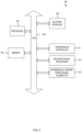
- FIG. 5 depicts an example computer, according to some embodiments.
- a computer 500 may include one or more processors 501 (possibly including multiple cores, multiple nodes, and/or implementing multi-threading, etc.).
- the computer 500 may include memory 507 .
- the memory 507 may be system memory or any one or more of the above already described possible implementations of machine-readable media.
- the computer 500 also may include a bus 503 and a network interface 505 .
- the computer 500 also may include a transmission controller 511 that may control signal transmissions, such as by the transmitter antenna 104 , as described herein.
- the computer 500 also may include a receiver signal processor 513 that may control receipt and processing of signals received by the first receiver antenna 106 and the second receiver antenna 108 .
- the functionality described herein may be implemented with an application-specific integrated circuit, in logic implemented in the processor 501 , in a co-processor on a peripheral device or card, etc. Further, implementations may include fewer or additional components not illustrated in FIG. 5 (e.g., video cards, audio cards, additional network interfaces, peripheral devices, etc.).
- the processor 501 and the network interface 505 may be coupled to the bus 503 . Although illustrated as being coupled to the bus 503 , the memory 507 may be coupled to the processor 501 .
- the computer 500 may be part of the logging tool 102 , communicatively coupled with the logging tool 102 , or otherwise utilized to achieve the functionality described herein.
- FIG. 6 depicts an example wireline system, according to some embodiments.
- a system 600 may be used in an illustrative logging environment with a drillstring removed, in accordance with some embodiments of the present disclosure.
- Subterranean operations may be conducted using a wireline system 620 once the drillstring has been removed, though, at times, some or all of the drillstring may remain in a borehole 614 during logging with the wireline system 620 .
- the wireline system 620 may include one or more logging tools 102 that may be suspended in the borehole 614 by a conveyance 616 (e.g., a cable, slickline, or coiled tubing).
- the logging tool 102 may be communicatively coupled to the conveyance 615 .
- the conveyance 615 may contain conductors for transporting power to the wireline system 620 and telemetry from the logging tool 626 to a logging facility 644 .
- the logging facility 644 may comprises an intermediate tensor-based calibrator capable enabling the logging tool 102 to utilize signal information without prior knowledge of antenna tilt-angles, as described herein.
- the conveyance 615 may lack a conductor, as is often the case using slickline or coiled tubing, and the wireline system 620 may contain a control unit 634 that contains memory, one or more batteries, and/or one or more processors for performing operations and storing measurements.
- control unit 634 may be positioned at the surface, in the borehole (e.g., in the conveyance 615 and/or as part of the logging tool 102 ) or both (e.g., a portion of the processing may occur downhole and a portion may occur at the surface).
- the control unit 634 may include a control system or a control algorithm.
- a control system, an algorithm, or a set of machine-readable instructions may cause the control unit 634 to generate and provide an input signal to one or more elements of the logging tool 626 , such as the sensors along the logging tool 102 .
- the input signal may cause the sensors to be active or to output signals indicative of sensed properties.
- the logging facility 644 (shown in FIG.
- the control unit 634 which may be located in logging tool 102 , may perform one or more functions of the computing facility.
- the logging tool 102 may include a mandrel and a number of extendible arms coupled to the mandrel.
- One or more pads may be coupled to each of the extendible arms.
- Each of the pads may have a surface facing radially outward from the mandrel.
- at least a sensor may be disposed on the surface of each pad.
- the extendible arms may be extended outwards to a wall of the borehole to extend the surface of the pads outward against the wall of the borehole.
- the sensors of the pads of each extendible arm may detect image data to create captured images of the formation surrounding the borehole.
- FIG. 7 depicts an example drilling rig system, according to some embodiments.
- a system 764 may also form a portion of a drilling rig 702 located at the surface 704 of a well 706 .
- Drilling of oil and gas wells is commonly carried out using a string of drill pipes connected together so as to form a drilling string 708 that may be lowered through a rotary table 710 into a wellbore or borehole 712 .
- a drilling platform 786 may be equipped with a derrick 788 that supports a hoist.
- a computer system 790 (e.g., similar to the computer 500 ) may be communicatively coupled to any measurement devices attached to the system 764 and may configured the system 764 to utilize signal information without prior knowledge of antenna tilt-angles, as described herein.
- the drilling rig 702 may thus provide support for the drill string 708 .
- the drill string 708 may operate to penetrate the rotary table 710 for drilling the borehole 712 through subsurface formations 714 .
- the drill string 708 may include a Kelly 716 , drill pipe 718 , and a bottom hole assembly 720 , perhaps located at the lower portion of the drill pipe 718 .
- the bottom hole assembly 720 may include drill collars 722 , a down hole tool 724 , and a drill bit 726 .
- the drill bit 726 may operate to create a borehole 712 by penetrating the surface 704 and subsurface formations 714 .
- the down hole tool 724 (e.g., similar to the logging tool 102 ) may comprise any of a number of different types of tools including MWD tools, LWD tools, and others.
- the drill string 708 (perhaps including the Kelly 716 , the drill pipe 718 , and the bottom hole assembly 720 ) may be rotated by the rotary table 710 .
- the bottom hole assembly 720 may also be rotated by a motor (e.g., a mud motor) that may be located down hole.
- the drill collars 722 may be used to add weight to the drill bit 726 .
- the drill collars 722 may also operate to stiffen the bottom hole assembly 720 , allowing the bottom hole assembly 720 to transfer the added weight to the drill bit 726 , and in turn, to assist the drill bit 726 in penetrating the surface 704 and subsurface formations 714 .
- a mud pump 732 may pump drilling fluid (sometimes known by those of ordinary skill in the art as “drilling mud”) from a mud pit 734 through a hose 736 into the drill pipe 718 and down to the drill bit 726 .
- the drilling fluid may flow out from the drill bit 726 and be returned to the surface 704 through an annular area 740 between the drill pipe 718 and the sides of the borehole 712 .
- the drilling fluid may then be returned to the mud pit 734 , where such fluid may be filtered.
- the drilling fluid may be used to cool the drill bit 726 , as well as to provide lubrication for the drill bit 726 during drilling operations.
- the drilling fluid may be used to remove subsurface formation 714 cuttings created by operating the drill bit 726 . It may be the images of these cuttings that many implementations operate to acquire and process.
- FIG. 8 depicts a flowchart of example operations for configuring a logging tool to utilize signal information independent of antenna tilt-angles, according to some embodiments.
- the operations may include detecting, via a first receiver of a tool, a first measurement of a first signal transmitted by a transmitter of the tool into a substantially non-conductive material, wherein the first receiver is oriented at a first tilt angle and the transmitter is oriented at a second tilt angle (block 802 ).
- the operations may include detecting, via a second receiver of the tool, a second measurement of the first signal.
- the operations may include determining, based on the first and second measurements, a first tensor including values depending on the first tilt angle and the second tilt angle.
- the operations may include conveying the tool into a first wellbore formed in a first subsurface formation.
- the operations may include detecting, via the first receiver, a third measurement of a second signal transmitted by the transmitter into the first subsurface formation.
- the operations may include detecting, via the second receiver, a fourth measurement of the second signal.
- the operations may include determining, based on the third and fourth measurements, a second tensor including values depending on the first tilt angle, and the second tilt angle.
- the operations also may include determining a third tensor based on a relationship between the first tensor and the second tensor, wherein the third tensor includes values independent of the first tilt angle and the second tilt angle.
- Embodiment #1 A method comprising: detecting, via a first receiver of a tool, a first measurement of a first signal transmitted by a transmitter of the tool into a substantially non-conductive material, wherein the first receiver is oriented at a first tilt angle and the transmitter is oriented at a second tilt angle; detecting, via a second receiver of the tool, a second measurement of the first signal; wherein the second receiver is oriented at a third tilt angle; determining, based on the first and second measurements, a first tensor including values depending on the first tilt angle, second tilt angle and the third tilt angle; conveying the tool into a first wellbore formed in a subsurface formation; detecting, via the first receiver, a third measurement of a second signal transmitted by the transmitter into the subsurface formation; detecting, via the second receiver, a fourth measurement of the second signal; determining, based on the third and fourth measurements, a second tensor including values depending on the first tilt angle, the second tilt angle and the third tilt angle; and determining
- Embodiment #2 The method of Embodiment #1 further comprising:
- Embodiment #3 The method of any one of Embodiments #1-2, further comprising: determining a tool response on the third tensor; determining a property of the subsurface formation based on the tool response.
- Embodiment #4 The method of Embodiment #2, further comprising:
- Embodiment #5 The method of any one of Embodiments #1-4, wherein the tool has a cylindrical shape and the first tilt angle, the second tilt angle and the third tilt angle are measured relative to a longitudinal axis of the tool.
- Embodiment #6 The method of any one of Embodiments #1-5, wherein the substantially non-conductive material is air.
- Embodiment #7 The method of any one of Embodiments #1-6, wherein the third tilt angle is an additive inverse of the first tilt angle.
- Embodiment #8 A non-transitory, computer-readable medium having instructions stored thereon that are executable by a processor to cause the processor to: receive a first measurement, detected by a first receiver of a tool, of a first signal transmitted by a transmitter of the tool into a substantially non-conductive material, wherein the first receiver is oriented at a first tilt angle and the transmitter is oriented at a second tilt angle; receive a second measurement of the first signal that is detected by a second receiver of the tool, wherein the second receiver is oriented at a third tilt angle; determine, based on the first and second measurements, a first tensor including values depending on the first tilt angle and the second tilt angle; receive a third measurement of a second signal, detected by the first receiver and transmitted by the transmitter into a subsurface formation after the tool is conveyed into a first wellbore formed in the subsurface formation; receive a fourth measurement, detected by the second receiver, of the second signal; determine, based on the third and fourth measurements, a second tensor including
- Embodiment #9 The non-transitory, computer-readable medium of Embodiment #8, wherein the instructions comprise instructions executable by the processor to cause the processor to provide the third tensor as input to an inversion process.
- Embodiment #10 The non-transitory, computer-readable medium of any one of Embodiments #8-9, wherein the instructions comprise instructions executable by the processor to cause the processor to determine a tool response based on the third tensor; and determine a property of the subsurface formation based on the tool response.
- Embodiment #11 The non-transitory, computer-readable medium of any one of Embodiments #8-10, wherein the instructions comprise instructions executable by the processor to cause the processor to: perform a downhole operation based on the inverted formation property.
- Embodiment #12 The non-transitory, computer-readable medium of any one of Embodiments #8-11, wherein the tool has a cylindrical shape and the first tilt angle and the second tilt angle are measured relative to a longitudinal axis of the tool.
- Embodiment #13 The non-transitory, computer-readable medium of any one of Embodiments #8-12, wherein the substantially non-conductive material is air.
- Embodiment #14 The non-transitory, computer-readable medium of any one of Embodiments #8-13, wherein the third tilt angle is an additive inverse of the first tilt angle.
- Embodiment #15 A system comprising: a downhole tool comprising, a transmitter to transmit a first signal into a substantially non-conductive material; a first receiver oriented at a first tilt angle, wherein the transmitter is oriented at a second tilt angle, wherein the first receiver is to detect a first measurement of the first signal; and a second receiver to detect a second measurement of the first signal, wherein a second receiver oriented at a third tilt angle; a processor; and a machine-readable medium having instructions stored thereon that are executable by the processor to cause the processor to, determine, based on the first and second measurements, a first tensor including values depending on the first tilt angle and the second tilt angle, wherein the downhole tool is to be conveyed into a first wellbore formed in a subsurface formation, wherein the transmitter is to transmit a second signal into the subsurface formation, the first receiver to detect a third measurement of the second signal and the second receiver to detect a fourth measurement of the second signal; determine, based on the third and fourth
- Embodiment #16 The system of Embodiment #15, wherein the instructions comprise instructions executable by the processor to cause the processor to provide the third tensor as input to an inversion process.
- Embodiment #17 The system of any one of Embodiments #15-16, wherein the instructions comprise instructions executable by the processor to cause the processor to determine a tool response based on the third tensor; and determine a property of the subsurface formation based on the tool response.
- Embodiment #18 The system of any one of Embodiments #15-17, wherein the instructions comprise instructions executable by the processor to cause the processor to perform a downhole operation based on the inverted formation property.
- Embodiment #19 The system of any one of Embodiments #15-18, wherein the downhole tool has a cylindrical shape and the first tilt angle and the second tilt angle are measured relative to a longitudinal axis of the downhole tool.
- Embodiment #20 The system of any one of Embodiments #15-19, wherein the substantially non-conductive material is air.
- the term “or” is inclusive unless otherwise explicitly noted. Thus, the phrase “at least one of A, B, or C” is satisfied by any element from the set ⁇ A, B, C ⁇ or any combination thereof, including multiples of any element.
Abstract
Description
Z TR1(β)=A TR1 cos(2β+βTR1)+C TR1 cos β+D TR1 sin β+E TR1 (3)
Z TR2(β)=A TR2 cos(2β+βTR2)+C TR2 cos β+D TR2 sin β+E TR2 (4)
where ATR1, CTR1, DTR1, ETR1, ATR2, CTR2, DTR2, and ETR2 are coefficients of each of the geometric terms of the Fourier transform. The Fourier transform coefficients are further given by Equations 5 to 11, below:
where C is a multi-component intermediate tensor representing the cross-component responses Cij (where i=x, y, z and j=x, y, z), and where Cij are independent of the transmitter angle θt and the receiver angle θr. The components of the intermediate tensor C are related to the components of the tensor Z as shown in Equations 12 to 17, below.
C xx =Z xx sin θt sin θr (12)
C yy =Z yy sin θt sin θr (13)
C zz =Z zz cos θt cos θr (14)
C xz =Z xz sin θt cos θr (15)
C zx =Z zx cos θt sin θr (16)
C xy =C yx =C zy =C yz=0 (17)
R may be an arbitrary test formation—for example a one-dimensional formation with an arbitrary number of layers.
where CxxAir, CyyAir, CzzAir, are the diagonal components of the intermediate tensor C in air, where ATR1Air, ETR1Air, and ETR2Air are the coefficients of the Fourier components in air, and where βTR1Air and βTR2Air are the tool face angles for the
where CxxAir, CyyAir, CzzAir, CxzAir, and CzxAir are the components of the intermediate tensor C in air, and other terms are as previously described.
where cross-components Cxy, Zxy, Cyx, Zyx, Czy, Zzy, Cyz and Zyz are zero.
where ZxxAir, ZyyAir, ZzzAir, ZxzAir, and ZzxAir are the non-zero components of the response tensor Z in air.
Z xzAir =Z zxAir=√{square root over (Z xxAir Z zzAir)} (44)
where ZxzAir and ZzxAir may be approximated from the ZxxAir and ZzzAir components in air.
where ZxxCal, ZyyCal, and ZzzCal are the calibrated cross-component response factors and are independent from the transmitter angle θt and the receiver angle θr, because Cij and CijAir are independent of the transmitter angle θt and the receiver angle θr.
When the transmitter angle θt is not equal to the receiver angle θr, the trigonometric terms do not cancel out. However, as the transmitter angle θt and the receiver angle θr do not change (i.e., the antenna orientation angles are static once the tool is constructed), the trigonometric terms become constant multiplier terms, where the constants are a real number. This is expressed in Equations 52-53, below:
where Constant1 and Constant2 are constants across different formations and different depths as they are properties of the unchanging the transmitter angle θt and the receiver angle θ, of the
Claims (20)
Priority Applications (2)
| Application Number | Priority Date | Filing Date | Title |
|---|---|---|---|
| US17/584,220 US11876567B2 (en) | 2022-01-25 | 2022-01-25 | Electromagnetic tool calibration for tilted antennas with undetermined orientation angles |
| PCT/US2022/070354 WO2023146678A1 (en) | 2022-01-25 | 2022-01-26 | Electromagnetic tool calibration for tilted antennas with undetermined orientation angles |
Applications Claiming Priority (1)
| Application Number | Priority Date | Filing Date | Title |
|---|---|---|---|
| US17/584,220 US11876567B2 (en) | 2022-01-25 | 2022-01-25 | Electromagnetic tool calibration for tilted antennas with undetermined orientation angles |
Publications (2)
| Publication Number | Publication Date |
|---|---|
| US20230239059A1 US20230239059A1 (en) | 2023-07-27 |
| US11876567B2 true US11876567B2 (en) | 2024-01-16 |
Family
ID=87314680
Family Applications (1)
| Application Number | Title | Priority Date | Filing Date |
|---|---|---|---|
| US17/584,220 Active 2042-08-04 US11876567B2 (en) | 2022-01-25 | 2022-01-25 | Electromagnetic tool calibration for tilted antennas with undetermined orientation angles |
Country Status (2)
| Country | Link |
|---|---|
| US (1) | US11876567B2 (en) |
| WO (1) | WO2023146678A1 (en) |
Citations (9)
| Publication number | Priority date | Publication date | Assignee | Title |
|---|---|---|---|---|
| WO2011129828A1 (en) | 2010-04-15 | 2011-10-20 | Halliburton Energy Services, Inc. | Processing and geosteering with a rotating tool |
| US20130043884A1 (en) | 2011-08-17 | 2013-02-21 | Baker Hughes Incorporated | Method and apparatus for calibrating deep-reading multi-component induction tools with minimal ground effects |
| US20150322774A1 (en) | 2012-06-25 | 2015-11-12 | Halliburton Energy Services, Inc. | Tilted antenna logging systems and methods yielding robust measurement signals |
| US20170261636A1 (en) | 2016-03-14 | 2017-09-14 | Baker Hughes Incorporated | Method and apparatus for corection of transient electromagnetic signals to remove a pipe response |
| US20190137646A1 (en) | 2017-12-01 | 2019-05-09 | Schlumberger Technology Corporation | Calibration of electromagnetic measurement tool |
| US10295697B2 (en) * | 2013-01-30 | 2019-05-21 | Halliburton Energy Services, Inc. | Determination of true formation resistivity |
| US10788601B2 (en) | 2016-10-04 | 2020-09-29 | Halliburton Energy Services, Inc. | Tunable dipole moment for formation measurements |
| US20200309984A1 (en) * | 2018-06-07 | 2020-10-01 | Halliburton Energy Services, Inc. | Method Of Determining Full Green's Tensor With Resistivity Measurement |
| US20200408950A1 (en) | 2018-11-16 | 2020-12-31 | Halliburton Energy Services, Inc. | Air-hang calibration for resistivity-logging tool |
-
2022
- 2022-01-25 US US17/584,220 patent/US11876567B2/en active Active
- 2022-01-26 WO PCT/US2022/070354 patent/WO2023146678A1/en unknown
Patent Citations (9)
| Publication number | Priority date | Publication date | Assignee | Title |
|---|---|---|---|---|
| WO2011129828A1 (en) | 2010-04-15 | 2011-10-20 | Halliburton Energy Services, Inc. | Processing and geosteering with a rotating tool |
| US20130043884A1 (en) | 2011-08-17 | 2013-02-21 | Baker Hughes Incorporated | Method and apparatus for calibrating deep-reading multi-component induction tools with minimal ground effects |
| US20150322774A1 (en) | 2012-06-25 | 2015-11-12 | Halliburton Energy Services, Inc. | Tilted antenna logging systems and methods yielding robust measurement signals |
| US10295697B2 (en) * | 2013-01-30 | 2019-05-21 | Halliburton Energy Services, Inc. | Determination of true formation resistivity |
| US20170261636A1 (en) | 2016-03-14 | 2017-09-14 | Baker Hughes Incorporated | Method and apparatus for corection of transient electromagnetic signals to remove a pipe response |
| US10788601B2 (en) | 2016-10-04 | 2020-09-29 | Halliburton Energy Services, Inc. | Tunable dipole moment for formation measurements |
| US20190137646A1 (en) | 2017-12-01 | 2019-05-09 | Schlumberger Technology Corporation | Calibration of electromagnetic measurement tool |
| US20200309984A1 (en) * | 2018-06-07 | 2020-10-01 | Halliburton Energy Services, Inc. | Method Of Determining Full Green's Tensor With Resistivity Measurement |
| US20200408950A1 (en) | 2018-11-16 | 2020-12-31 | Halliburton Energy Services, Inc. | Air-hang calibration for resistivity-logging tool |
Non-Patent Citations (1)
| Title |
|---|
| PCT Application No. PCT/US2022/070354, International Search Report and Written Opinion, dated Oct. 7, 2022 , 9 pages. |
Also Published As
| Publication number | Publication date |
|---|---|
| US20230239059A1 (en) | 2023-07-27 |
| WO2023146678A1 (en) | 2023-08-03 |
Similar Documents
| Publication | Publication Date | Title |
|---|---|---|
| US9664816B2 (en) | Fracture detection and characterization using resistivity images | |
| US20150355368A1 (en) | Methods and systems for determining formation parameters using a rotating tool equipped with tilted antenna loops | |
| US9103928B2 (en) | Methods and systems for analyzing formation properties when performing subterranean operations | |
| US10295698B2 (en) | Multi-component induction logging systems and methods using selected frequency inversion | |
| US10788601B2 (en) | Tunable dipole moment for formation measurements | |
| EP3129586B1 (en) | Multiaxial well logging instrument response in dipping and crossbedded formations | |
| US10365395B2 (en) | Multi-component induction logging systems and methods using blended-model inversion | |
| NO20170745A1 (en) | Shoulder effect reduction | |
| US11035976B2 (en) | Decoupling tensor components without matrix inversion | |
| US20180038987A1 (en) | Induction logging borehole correction for water-based mud | |
| US9823380B2 (en) | Compensated borehole and pipe survey tool with conformable sensors | |
| US11876567B2 (en) | Electromagnetic tool calibration for tilted antennas with undetermined orientation angles | |
| US10962676B2 (en) | Signal processing of a multi-sub rotational resistivity logging tool | |
| US10324219B2 (en) | Identifying unconventional formations | |
| US11874424B2 (en) | Determining formation properties based on multi-component azimuthal measurements | |
| US11307322B2 (en) | Mixed inversion using a coarse layer model | |
| US11953639B2 (en) | Cross-component response interpolation for coaxially oriented antennas in an electromagnetic tool | |
| CN108291438A (en) | The method measured for inverting electromagnetic logging | |
| US10508535B2 (en) | Method for steering a well path perpendicular to vertical fractures for enhanced production efficiency |
Legal Events
| Date | Code | Title | Description |
|---|---|---|---|
| AS | Assignment |
Owner name: HALLIBURTON ENERGY SERVICES, INC., TEXAS Free format text: ASSIGNMENT OF ASSIGNORS INTEREST;ASSIGNORS:FAN, YIJING;WU, HSU-HSIANG;MA, JIN;AND OTHERS;SIGNING DATES FROM 20220105 TO 20220125;REEL/FRAME:058765/0662 |
|
| FEPP | Fee payment procedure |
Free format text: ENTITY STATUS SET TO UNDISCOUNTED (ORIGINAL EVENT CODE: BIG.); ENTITY STATUS OF PATENT OWNER: LARGE ENTITY |
|
| STPP | Information on status: patent application and granting procedure in general |
Free format text: DOCKETED NEW CASE - READY FOR EXAMINATION |
|
| STPP | Information on status: patent application and granting procedure in general |
Free format text: NOTICE OF ALLOWANCE MAILED -- APPLICATION RECEIVED IN OFFICE OF PUBLICATIONS |
|
| STPP | Information on status: patent application and granting procedure in general |
Free format text: PUBLICATIONS -- ISSUE FEE PAYMENT RECEIVED |
|
| STPP | Information on status: patent application and granting procedure in general |
Free format text: PUBLICATIONS -- ISSUE FEE PAYMENT VERIFIED |
|
| STCF | Information on status: patent grant |
Free format text: PATENTED CASE |