US11872143B2 - Spinal fusion implant - Google Patents
Spinal fusion implant Download PDFInfo
- Publication number
- US11872143B2 US11872143B2 US16/565,003 US201916565003A US11872143B2 US 11872143 B2 US11872143 B2 US 11872143B2 US 201916565003 A US201916565003 A US 201916565003A US 11872143 B2 US11872143 B2 US 11872143B2
- Authority
- US
- United States
- Prior art keywords
- blade
- implant
- actuating component
- housing
- channel
- Prior art date
- Legal status (The legal status is an assumption and is not a legal conclusion. Google has not performed a legal analysis and makes no representation as to the accuracy of the status listed.)
- Active, expires
Links
- 239000007943 implant Substances 0.000 title claims abstract description 252
- 230000004927 fusion Effects 0.000 title description 17
- 230000007704 transition Effects 0.000 claims description 4
- 230000001045 lordotic effect Effects 0.000 claims 1
- 238000003780 insertion Methods 0.000 description 45
- 230000037431 insertion Effects 0.000 description 45
- 239000000463 material Substances 0.000 description 22
- 210000000988 bone and bone Anatomy 0.000 description 21
- 238000000034 method Methods 0.000 description 13
- 230000008468 bone growth Effects 0.000 description 12
- 230000033001 locomotion Effects 0.000 description 11
- 238000013459 approach Methods 0.000 description 9
- 230000001737 promoting effect Effects 0.000 description 9
- 238000002513 implantation Methods 0.000 description 7
- 230000008569 process Effects 0.000 description 7
- 230000008878 coupling Effects 0.000 description 6
- 238000010168 coupling process Methods 0.000 description 6
- 238000005859 coupling reaction Methods 0.000 description 6
- 239000010936 titanium Substances 0.000 description 5
- 108010007726 Bone Morphogenetic Proteins Proteins 0.000 description 4
- 102000007350 Bone Morphogenetic Proteins Human genes 0.000 description 4
- 229940112869 bone morphogenetic protein Drugs 0.000 description 4
- 230000003116 impacting effect Effects 0.000 description 4
- 230000000670 limiting effect Effects 0.000 description 4
- 239000007787 solid Substances 0.000 description 4
- 208000007623 Lordosis Diseases 0.000 description 3
- 239000004696 Poly ether ether ketone Substances 0.000 description 3
- RTAQQCXQSZGOHL-UHFFFAOYSA-N Titanium Chemical compound [Ti] RTAQQCXQSZGOHL-UHFFFAOYSA-N 0.000 description 3
- 238000004873 anchoring Methods 0.000 description 3
- 230000008901 benefit Effects 0.000 description 3
- 238000002594 fluoroscopy Methods 0.000 description 3
- 238000004519 manufacturing process Methods 0.000 description 3
- 229910052751 metal Inorganic materials 0.000 description 3
- 239000002184 metal Substances 0.000 description 3
- 230000035515 penetration Effects 0.000 description 3
- 229920002530 polyetherether ketone Polymers 0.000 description 3
- 230000002787 reinforcement Effects 0.000 description 3
- 210000000130 stem cell Anatomy 0.000 description 3
- 239000000126 substance Substances 0.000 description 3
- 238000001356 surgical procedure Methods 0.000 description 3
- 229910052719 titanium Inorganic materials 0.000 description 3
- VTYYLEPIZMXCLO-UHFFFAOYSA-L Calcium carbonate Chemical compound [Ca+2].[O-]C([O-])=O VTYYLEPIZMXCLO-UHFFFAOYSA-L 0.000 description 2
- 102000008186 Collagen Human genes 0.000 description 2
- 108010035532 Collagen Proteins 0.000 description 2
- 102000018233 Fibroblast Growth Factor Human genes 0.000 description 2
- 108050007372 Fibroblast Growth Factor Proteins 0.000 description 2
- 102000010780 Platelet-Derived Growth Factor Human genes 0.000 description 2
- 108010038512 Platelet-Derived Growth Factor Proteins 0.000 description 2
- 208000007103 Spondylolisthesis Diseases 0.000 description 2
- 229910001069 Ti alloy Inorganic materials 0.000 description 2
- 210000001015 abdomen Anatomy 0.000 description 2
- 210000000709 aorta Anatomy 0.000 description 2
- 238000000149 argon plasma sintering Methods 0.000 description 2
- OSGAYBCDTDRGGQ-UHFFFAOYSA-L calcium sulfate Chemical compound [Ca+2].[O-]S([O-])(=O)=O OSGAYBCDTDRGGQ-UHFFFAOYSA-L 0.000 description 2
- 239000011248 coating agent Substances 0.000 description 2
- 238000000576 coating method Methods 0.000 description 2
- 229920001436 collagen Polymers 0.000 description 2
- 229940126864 fibroblast growth factor Drugs 0.000 description 2
- 238000001746 injection moulding Methods 0.000 description 2
- 230000013011 mating Effects 0.000 description 2
- 150000002739 metals Chemical class 0.000 description 2
- 230000036961 partial effect Effects 0.000 description 2
- 230000000149 penetrating effect Effects 0.000 description 2
- 102000004169 proteins and genes Human genes 0.000 description 2
- 108090000623 proteins and genes Proteins 0.000 description 2
- 229920002994 synthetic fiber Polymers 0.000 description 2
- 229910021324 titanium aluminide Inorganic materials 0.000 description 2
- 238000013519 translation Methods 0.000 description 2
- QORWJWZARLRLPR-UHFFFAOYSA-H tricalcium bis(phosphate) Chemical compound [Ca+2].[Ca+2].[Ca+2].[O-]P([O-])([O-])=O.[O-]P([O-])([O-])=O QORWJWZARLRLPR-UHFFFAOYSA-H 0.000 description 2
- 238000010146 3D printing Methods 0.000 description 1
- IYMAXBFPHPZYIK-BQBZGAKWSA-N Arg-Gly-Asp Chemical class NC(N)=NCCC[C@H](N)C(=O)NCC(=O)N[C@@H](CC(O)=O)C(O)=O IYMAXBFPHPZYIK-BQBZGAKWSA-N 0.000 description 1
- 208000010392 Bone Fractures Diseases 0.000 description 1
- 108010049931 Bone Morphogenetic Protein 2 Proteins 0.000 description 1
- 108010049955 Bone Morphogenetic Protein 4 Proteins 0.000 description 1
- 108010049974 Bone Morphogenetic Protein 6 Proteins 0.000 description 1
- 108010049870 Bone Morphogenetic Protein 7 Proteins 0.000 description 1
- 102100028728 Bone morphogenetic protein 1 Human genes 0.000 description 1
- 108090000654 Bone morphogenetic protein 1 Proteins 0.000 description 1
- 102100024506 Bone morphogenetic protein 2 Human genes 0.000 description 1
- 102100024505 Bone morphogenetic protein 4 Human genes 0.000 description 1
- 102100022525 Bone morphogenetic protein 6 Human genes 0.000 description 1
- 102100022544 Bone morphogenetic protein 7 Human genes 0.000 description 1
- OYPRJOBELJOOCE-UHFFFAOYSA-N Calcium Chemical compound [Ca] OYPRJOBELJOOCE-UHFFFAOYSA-N 0.000 description 1
- 229910000684 Cobalt-chrome Inorganic materials 0.000 description 1
- 206010017076 Fracture Diseases 0.000 description 1
- 206010061246 Intervertebral disc degeneration Diseases 0.000 description 1
- 206010028980 Neoplasm Diseases 0.000 description 1
- 229910000883 Ti6Al4V Inorganic materials 0.000 description 1
- 208000027418 Wounds and injury Diseases 0.000 description 1
- 210000003489 abdominal muscle Anatomy 0.000 description 1
- 239000000654 additive Substances 0.000 description 1
- 230000000996 additive effect Effects 0.000 description 1
- 210000003484 anatomy Anatomy 0.000 description 1
- 108010072041 arginyl-glycyl-aspartic acid Proteins 0.000 description 1
- 239000011230 binding agent Substances 0.000 description 1
- 239000000560 biocompatible material Substances 0.000 description 1
- 229920000249 biocompatible polymer Polymers 0.000 description 1
- 239000012620 biological material Substances 0.000 description 1
- 210000002805 bone matrix Anatomy 0.000 description 1
- 239000011575 calcium Substances 0.000 description 1
- 229910052791 calcium Inorganic materials 0.000 description 1
- 229910000019 calcium carbonate Inorganic materials 0.000 description 1
- 239000001506 calcium phosphate Substances 0.000 description 1
- 235000011010 calcium phosphates Nutrition 0.000 description 1
- 210000004027 cell Anatomy 0.000 description 1
- 239000000919 ceramic Substances 0.000 description 1
- 238000006243 chemical reaction Methods 0.000 description 1
- 239000010952 cobalt-chrome Substances 0.000 description 1
- 238000000748 compression moulding Methods 0.000 description 1
- 230000006378 damage Effects 0.000 description 1
- 230000003247 decreasing effect Effects 0.000 description 1
- 208000018180 degenerative disc disease Diseases 0.000 description 1
- 230000001419 dependent effect Effects 0.000 description 1
- 238000013461 design Methods 0.000 description 1
- 238000003618 dip coating Methods 0.000 description 1
- 230000000694 effects Effects 0.000 description 1
- 238000010894 electron beam technology Methods 0.000 description 1
- 238000001125 extrusion Methods 0.000 description 1
- 239000003102 growth factor Substances 0.000 description 1
- 229940088597 hormone Drugs 0.000 description 1
- 239000005556 hormone Substances 0.000 description 1
- 229910052588 hydroxylapatite Inorganic materials 0.000 description 1
- 238000003384 imaging method Methods 0.000 description 1
- 208000015181 infectious disease Diseases 0.000 description 1
- 230000002401 inhibitory effect Effects 0.000 description 1
- 208000014674 injury Diseases 0.000 description 1
- 230000003993 interaction Effects 0.000 description 1
- 208000021600 intervertebral disc degenerative disease Diseases 0.000 description 1
- 238000011068 loading method Methods 0.000 description 1
- 238000003754 machining Methods 0.000 description 1
- 239000003550 marker Substances 0.000 description 1
- 239000011159 matrix material Substances 0.000 description 1
- 230000007246 mechanism Effects 0.000 description 1
- 210000002901 mesenchymal stem cell Anatomy 0.000 description 1
- 238000003801 milling Methods 0.000 description 1
- 238000012986 modification Methods 0.000 description 1
- 230000004048 modification Effects 0.000 description 1
- 230000000921 morphogenic effect Effects 0.000 description 1
- 238000000465 moulding Methods 0.000 description 1
- 210000000963 osteoblast Anatomy 0.000 description 1
- 230000004820 osteoconduction Effects 0.000 description 1
- XYJRXVWERLGGKC-UHFFFAOYSA-D pentacalcium;hydroxide;triphosphate Chemical compound [OH-].[Ca+2].[Ca+2].[Ca+2].[Ca+2].[Ca+2].[O-]P([O-])([O-])=O.[O-]P([O-])([O-])=O.[O-]P([O-])([O-])=O XYJRXVWERLGGKC-UHFFFAOYSA-D 0.000 description 1
- 229920001652 poly(etherketoneketone) Polymers 0.000 description 1
- 230000002980 postoperative effect Effects 0.000 description 1
- 239000000843 powder Substances 0.000 description 1
- 238000002360 preparation method Methods 0.000 description 1
- 238000007639 printing Methods 0.000 description 1
- 102000004196 processed proteins & peptides Human genes 0.000 description 1
- 108090000765 processed proteins & peptides Proteins 0.000 description 1
- 206010039722 scoliosis Diseases 0.000 description 1
- 208000005198 spinal stenosis Diseases 0.000 description 1
- 239000007921 spray Substances 0.000 description 1
- 238000005507 spraying Methods 0.000 description 1
- 230000006641 stabilisation Effects 0.000 description 1
- 238000011105 stabilization Methods 0.000 description 1
- 239000010935 stainless steel Substances 0.000 description 1
- 229910001220 stainless steel Inorganic materials 0.000 description 1
- 229920001059 synthetic polymer Polymers 0.000 description 1
- 238000012360 testing method Methods 0.000 description 1
- -1 titanium Chemical class 0.000 description 1
- 238000012546 transfer Methods 0.000 description 1
- 238000001721 transfer moulding Methods 0.000 description 1
- 238000010200 validation analysis Methods 0.000 description 1
- 230000000007 visual effect Effects 0.000 description 1
- 238000012800 visualization Methods 0.000 description 1
Images


Classifications
-
- A—HUMAN NECESSITIES
- A61—MEDICAL OR VETERINARY SCIENCE; HYGIENE
- A61F—FILTERS IMPLANTABLE INTO BLOOD VESSELS; PROSTHESES; DEVICES PROVIDING PATENCY TO, OR PREVENTING COLLAPSING OF, TUBULAR STRUCTURES OF THE BODY, e.g. STENTS; ORTHOPAEDIC, NURSING OR CONTRACEPTIVE DEVICES; FOMENTATION; TREATMENT OR PROTECTION OF EYES OR EARS; BANDAGES, DRESSINGS OR ABSORBENT PADS; FIRST-AID KITS
- A61F2/00—Filters implantable into blood vessels; Prostheses, i.e. artificial substitutes or replacements for parts of the body; Appliances for connecting them with the body; Devices providing patency to, or preventing collapsing of, tubular structures of the body, e.g. stents
- A61F2/02—Prostheses implantable into the body
- A61F2/30—Joints
- A61F2/46—Special tools or methods for implanting or extracting artificial joints, accessories, bone grafts or substitutes, or particular adaptations therefor
- A61F2/4603—Special tools or methods for implanting or extracting artificial joints, accessories, bone grafts or substitutes, or particular adaptations therefor for insertion or extraction of endoprosthetic joints or of accessories thereof
- A61F2/4611—Special tools or methods for implanting or extracting artificial joints, accessories, bone grafts or substitutes, or particular adaptations therefor for insertion or extraction of endoprosthetic joints or of accessories thereof of spinal prostheses
-
- A—HUMAN NECESSITIES
- A61—MEDICAL OR VETERINARY SCIENCE; HYGIENE
- A61F—FILTERS IMPLANTABLE INTO BLOOD VESSELS; PROSTHESES; DEVICES PROVIDING PATENCY TO, OR PREVENTING COLLAPSING OF, TUBULAR STRUCTURES OF THE BODY, e.g. STENTS; ORTHOPAEDIC, NURSING OR CONTRACEPTIVE DEVICES; FOMENTATION; TREATMENT OR PROTECTION OF EYES OR EARS; BANDAGES, DRESSINGS OR ABSORBENT PADS; FIRST-AID KITS
- A61F2/00—Filters implantable into blood vessels; Prostheses, i.e. artificial substitutes or replacements for parts of the body; Appliances for connecting them with the body; Devices providing patency to, or preventing collapsing of, tubular structures of the body, e.g. stents
- A61F2/02—Prostheses implantable into the body
- A61F2/30—Joints
- A61F2/44—Joints for the spine, e.g. vertebrae, spinal discs
- A61F2/4455—Joints for the spine, e.g. vertebrae, spinal discs for the fusion of spinal bodies, e.g. intervertebral fusion of adjacent spinal bodies, e.g. fusion cages
- A61F2/4465—Joints for the spine, e.g. vertebrae, spinal discs for the fusion of spinal bodies, e.g. intervertebral fusion of adjacent spinal bodies, e.g. fusion cages having a circular or kidney shaped cross-section substantially perpendicular to the axis of the spine
-
- A—HUMAN NECESSITIES
- A61—MEDICAL OR VETERINARY SCIENCE; HYGIENE
- A61F—FILTERS IMPLANTABLE INTO BLOOD VESSELS; PROSTHESES; DEVICES PROVIDING PATENCY TO, OR PREVENTING COLLAPSING OF, TUBULAR STRUCTURES OF THE BODY, e.g. STENTS; ORTHOPAEDIC, NURSING OR CONTRACEPTIVE DEVICES; FOMENTATION; TREATMENT OR PROTECTION OF EYES OR EARS; BANDAGES, DRESSINGS OR ABSORBENT PADS; FIRST-AID KITS
- A61F2/00—Filters implantable into blood vessels; Prostheses, i.e. artificial substitutes or replacements for parts of the body; Appliances for connecting them with the body; Devices providing patency to, or preventing collapsing of, tubular structures of the body, e.g. stents
- A61F2/02—Prostheses implantable into the body
- A61F2/30—Joints
- A61F2002/30001—Additional features of subject-matter classified in A61F2/28, A61F2/30 and subgroups thereof
- A61F2002/30316—The prosthesis having different structural features at different locations within the same prosthesis; Connections between prosthetic parts; Special structural features of bone or joint prostheses not otherwise provided for
- A61F2002/30329—Connections or couplings between prosthetic parts, e.g. between modular parts; Connecting elements
- A61F2002/30383—Connections or couplings between prosthetic parts, e.g. between modular parts; Connecting elements made by laterally inserting a protrusion, e.g. a rib into a complementarily-shaped groove
- A61F2002/30387—Dovetail connection
-
- A—HUMAN NECESSITIES
- A61—MEDICAL OR VETERINARY SCIENCE; HYGIENE
- A61F—FILTERS IMPLANTABLE INTO BLOOD VESSELS; PROSTHESES; DEVICES PROVIDING PATENCY TO, OR PREVENTING COLLAPSING OF, TUBULAR STRUCTURES OF THE BODY, e.g. STENTS; ORTHOPAEDIC, NURSING OR CONTRACEPTIVE DEVICES; FOMENTATION; TREATMENT OR PROTECTION OF EYES OR EARS; BANDAGES, DRESSINGS OR ABSORBENT PADS; FIRST-AID KITS
- A61F2/00—Filters implantable into blood vessels; Prostheses, i.e. artificial substitutes or replacements for parts of the body; Appliances for connecting them with the body; Devices providing patency to, or preventing collapsing of, tubular structures of the body, e.g. stents
- A61F2/02—Prostheses implantable into the body
- A61F2/30—Joints
- A61F2002/30001—Additional features of subject-matter classified in A61F2/28, A61F2/30 and subgroups thereof
- A61F2002/30316—The prosthesis having different structural features at different locations within the same prosthesis; Connections between prosthetic parts; Special structural features of bone or joint prostheses not otherwise provided for
- A61F2002/30329—Connections or couplings between prosthetic parts, e.g. between modular parts; Connecting elements
- A61F2002/30383—Connections or couplings between prosthetic parts, e.g. between modular parts; Connecting elements made by laterally inserting a protrusion, e.g. a rib into a complementarily-shaped groove
- A61F2002/3039—Connections or couplings between prosthetic parts, e.g. between modular parts; Connecting elements made by laterally inserting a protrusion, e.g. a rib into a complementarily-shaped groove with possibility of relative movement of the rib within the groove
-
- A—HUMAN NECESSITIES
- A61—MEDICAL OR VETERINARY SCIENCE; HYGIENE
- A61F—FILTERS IMPLANTABLE INTO BLOOD VESSELS; PROSTHESES; DEVICES PROVIDING PATENCY TO, OR PREVENTING COLLAPSING OF, TUBULAR STRUCTURES OF THE BODY, e.g. STENTS; ORTHOPAEDIC, NURSING OR CONTRACEPTIVE DEVICES; FOMENTATION; TREATMENT OR PROTECTION OF EYES OR EARS; BANDAGES, DRESSINGS OR ABSORBENT PADS; FIRST-AID KITS
- A61F2/00—Filters implantable into blood vessels; Prostheses, i.e. artificial substitutes or replacements for parts of the body; Appliances for connecting them with the body; Devices providing patency to, or preventing collapsing of, tubular structures of the body, e.g. stents
- A61F2/02—Prostheses implantable into the body
- A61F2/30—Joints
- A61F2002/30001—Additional features of subject-matter classified in A61F2/28, A61F2/30 and subgroups thereof
- A61F2002/30316—The prosthesis having different structural features at different locations within the same prosthesis; Connections between prosthetic parts; Special structural features of bone or joint prostheses not otherwise provided for
- A61F2002/30329—Connections or couplings between prosthetic parts, e.g. between modular parts; Connecting elements
- A61F2002/30405—Connections or couplings between prosthetic parts, e.g. between modular parts; Connecting elements made by screwing complementary threads machined on the parts themselves
-
- A—HUMAN NECESSITIES
- A61—MEDICAL OR VETERINARY SCIENCE; HYGIENE
- A61F—FILTERS IMPLANTABLE INTO BLOOD VESSELS; PROSTHESES; DEVICES PROVIDING PATENCY TO, OR PREVENTING COLLAPSING OF, TUBULAR STRUCTURES OF THE BODY, e.g. STENTS; ORTHOPAEDIC, NURSING OR CONTRACEPTIVE DEVICES; FOMENTATION; TREATMENT OR PROTECTION OF EYES OR EARS; BANDAGES, DRESSINGS OR ABSORBENT PADS; FIRST-AID KITS
- A61F2/00—Filters implantable into blood vessels; Prostheses, i.e. artificial substitutes or replacements for parts of the body; Appliances for connecting them with the body; Devices providing patency to, or preventing collapsing of, tubular structures of the body, e.g. stents
- A61F2/02—Prostheses implantable into the body
- A61F2/30—Joints
- A61F2002/30001—Additional features of subject-matter classified in A61F2/28, A61F2/30 and subgroups thereof
- A61F2002/30316—The prosthesis having different structural features at different locations within the same prosthesis; Connections between prosthetic parts; Special structural features of bone or joint prostheses not otherwise provided for
- A61F2002/30329—Connections or couplings between prosthetic parts, e.g. between modular parts; Connecting elements
- A61F2002/30476—Connections or couplings between prosthetic parts, e.g. between modular parts; Connecting elements locked by an additional locking mechanism
- A61F2002/30492—Connections or couplings between prosthetic parts, e.g. between modular parts; Connecting elements locked by an additional locking mechanism using a locking pin
-
- A—HUMAN NECESSITIES
- A61—MEDICAL OR VETERINARY SCIENCE; HYGIENE
- A61F—FILTERS IMPLANTABLE INTO BLOOD VESSELS; PROSTHESES; DEVICES PROVIDING PATENCY TO, OR PREVENTING COLLAPSING OF, TUBULAR STRUCTURES OF THE BODY, e.g. STENTS; ORTHOPAEDIC, NURSING OR CONTRACEPTIVE DEVICES; FOMENTATION; TREATMENT OR PROTECTION OF EYES OR EARS; BANDAGES, DRESSINGS OR ABSORBENT PADS; FIRST-AID KITS
- A61F2/00—Filters implantable into blood vessels; Prostheses, i.e. artificial substitutes or replacements for parts of the body; Appliances for connecting them with the body; Devices providing patency to, or preventing collapsing of, tubular structures of the body, e.g. stents
- A61F2/02—Prostheses implantable into the body
- A61F2/30—Joints
- A61F2002/30001—Additional features of subject-matter classified in A61F2/28, A61F2/30 and subgroups thereof
- A61F2002/30316—The prosthesis having different structural features at different locations within the same prosthesis; Connections between prosthetic parts; Special structural features of bone or joint prostheses not otherwise provided for
- A61F2002/30329—Connections or couplings between prosthetic parts, e.g. between modular parts; Connecting elements
- A61F2002/30476—Connections or couplings between prosthetic parts, e.g. between modular parts; Connecting elements locked by an additional locking mechanism
- A61F2002/30507—Connections or couplings between prosthetic parts, e.g. between modular parts; Connecting elements locked by an additional locking mechanism using a threaded locking member, e.g. a locking screw or a set screw
-
- A—HUMAN NECESSITIES
- A61—MEDICAL OR VETERINARY SCIENCE; HYGIENE
- A61F—FILTERS IMPLANTABLE INTO BLOOD VESSELS; PROSTHESES; DEVICES PROVIDING PATENCY TO, OR PREVENTING COLLAPSING OF, TUBULAR STRUCTURES OF THE BODY, e.g. STENTS; ORTHOPAEDIC, NURSING OR CONTRACEPTIVE DEVICES; FOMENTATION; TREATMENT OR PROTECTION OF EYES OR EARS; BANDAGES, DRESSINGS OR ABSORBENT PADS; FIRST-AID KITS
- A61F2/00—Filters implantable into blood vessels; Prostheses, i.e. artificial substitutes or replacements for parts of the body; Appliances for connecting them with the body; Devices providing patency to, or preventing collapsing of, tubular structures of the body, e.g. stents
- A61F2/02—Prostheses implantable into the body
- A61F2/30—Joints
- A61F2002/30001—Additional features of subject-matter classified in A61F2/28, A61F2/30 and subgroups thereof
- A61F2002/30316—The prosthesis having different structural features at different locations within the same prosthesis; Connections between prosthetic parts; Special structural features of bone or joint prostheses not otherwise provided for
- A61F2002/30329—Connections or couplings between prosthetic parts, e.g. between modular parts; Connecting elements
- A61F2002/30476—Connections or couplings between prosthetic parts, e.g. between modular parts; Connecting elements locked by an additional locking mechanism
- A61F2002/30515—Connections or couplings between prosthetic parts, e.g. between modular parts; Connecting elements locked by an additional locking mechanism using a locking wedge or block
-
- A—HUMAN NECESSITIES
- A61—MEDICAL OR VETERINARY SCIENCE; HYGIENE
- A61F—FILTERS IMPLANTABLE INTO BLOOD VESSELS; PROSTHESES; DEVICES PROVIDING PATENCY TO, OR PREVENTING COLLAPSING OF, TUBULAR STRUCTURES OF THE BODY, e.g. STENTS; ORTHOPAEDIC, NURSING OR CONTRACEPTIVE DEVICES; FOMENTATION; TREATMENT OR PROTECTION OF EYES OR EARS; BANDAGES, DRESSINGS OR ABSORBENT PADS; FIRST-AID KITS
- A61F2/00—Filters implantable into blood vessels; Prostheses, i.e. artificial substitutes or replacements for parts of the body; Appliances for connecting them with the body; Devices providing patency to, or preventing collapsing of, tubular structures of the body, e.g. stents
- A61F2/02—Prostheses implantable into the body
- A61F2/30—Joints
- A61F2002/30001—Additional features of subject-matter classified in A61F2/28, A61F2/30 and subgroups thereof
- A61F2002/30316—The prosthesis having different structural features at different locations within the same prosthesis; Connections between prosthetic parts; Special structural features of bone or joint prostheses not otherwise provided for
- A61F2002/30535—Special structural features of bone or joint prostheses not otherwise provided for
- A61F2002/30579—Special structural features of bone or joint prostheses not otherwise provided for with mechanically expandable devices, e.g. fixation devices
-
- A—HUMAN NECESSITIES
- A61—MEDICAL OR VETERINARY SCIENCE; HYGIENE
- A61F—FILTERS IMPLANTABLE INTO BLOOD VESSELS; PROSTHESES; DEVICES PROVIDING PATENCY TO, OR PREVENTING COLLAPSING OF, TUBULAR STRUCTURES OF THE BODY, e.g. STENTS; ORTHOPAEDIC, NURSING OR CONTRACEPTIVE DEVICES; FOMENTATION; TREATMENT OR PROTECTION OF EYES OR EARS; BANDAGES, DRESSINGS OR ABSORBENT PADS; FIRST-AID KITS
- A61F2/00—Filters implantable into blood vessels; Prostheses, i.e. artificial substitutes or replacements for parts of the body; Appliances for connecting them with the body; Devices providing patency to, or preventing collapsing of, tubular structures of the body, e.g. stents
- A61F2/02—Prostheses implantable into the body
- A61F2/30—Joints
- A61F2002/30001—Additional features of subject-matter classified in A61F2/28, A61F2/30 and subgroups thereof
- A61F2002/30316—The prosthesis having different structural features at different locations within the same prosthesis; Connections between prosthetic parts; Special structural features of bone or joint prostheses not otherwise provided for
- A61F2002/30535—Special structural features of bone or joint prostheses not otherwise provided for
- A61F2002/30593—Special structural features of bone or joint prostheses not otherwise provided for hollow
-
- A—HUMAN NECESSITIES
- A61—MEDICAL OR VETERINARY SCIENCE; HYGIENE
- A61F—FILTERS IMPLANTABLE INTO BLOOD VESSELS; PROSTHESES; DEVICES PROVIDING PATENCY TO, OR PREVENTING COLLAPSING OF, TUBULAR STRUCTURES OF THE BODY, e.g. STENTS; ORTHOPAEDIC, NURSING OR CONTRACEPTIVE DEVICES; FOMENTATION; TREATMENT OR PROTECTION OF EYES OR EARS; BANDAGES, DRESSINGS OR ABSORBENT PADS; FIRST-AID KITS
- A61F2/00—Filters implantable into blood vessels; Prostheses, i.e. artificial substitutes or replacements for parts of the body; Appliances for connecting them with the body; Devices providing patency to, or preventing collapsing of, tubular structures of the body, e.g. stents
- A61F2/02—Prostheses implantable into the body
- A61F2/30—Joints
- A61F2/30767—Special external or bone-contacting surface, e.g. coating for improving bone ingrowth
- A61F2/30771—Special external or bone-contacting surface, e.g. coating for improving bone ingrowth applied in original prostheses, e.g. holes or grooves
- A61F2002/30841—Sharp anchoring protrusions for impaction into the bone, e.g. sharp pins, spikes
-
- A—HUMAN NECESSITIES
- A61—MEDICAL OR VETERINARY SCIENCE; HYGIENE
- A61F—FILTERS IMPLANTABLE INTO BLOOD VESSELS; PROSTHESES; DEVICES PROVIDING PATENCY TO, OR PREVENTING COLLAPSING OF, TUBULAR STRUCTURES OF THE BODY, e.g. STENTS; ORTHOPAEDIC, NURSING OR CONTRACEPTIVE DEVICES; FOMENTATION; TREATMENT OR PROTECTION OF EYES OR EARS; BANDAGES, DRESSINGS OR ABSORBENT PADS; FIRST-AID KITS
- A61F2/00—Filters implantable into blood vessels; Prostheses, i.e. artificial substitutes or replacements for parts of the body; Appliances for connecting them with the body; Devices providing patency to, or preventing collapsing of, tubular structures of the body, e.g. stents
- A61F2/02—Prostheses implantable into the body
- A61F2/30—Joints
- A61F2/30767—Special external or bone-contacting surface, e.g. coating for improving bone ingrowth
- A61F2/30771—Special external or bone-contacting surface, e.g. coating for improving bone ingrowth applied in original prostheses, e.g. holes or grooves
- A61F2002/30878—Special external or bone-contacting surface, e.g. coating for improving bone ingrowth applied in original prostheses, e.g. holes or grooves with non-sharp protrusions, for instance contacting the bone for anchoring, e.g. keels, pegs, pins, posts, shanks, stems, struts
- A61F2002/30884—Fins or wings, e.g. longitudinal wings for preventing rotation within the bone cavity
-
- A—HUMAN NECESSITIES
- A61—MEDICAL OR VETERINARY SCIENCE; HYGIENE
- A61F—FILTERS IMPLANTABLE INTO BLOOD VESSELS; PROSTHESES; DEVICES PROVIDING PATENCY TO, OR PREVENTING COLLAPSING OF, TUBULAR STRUCTURES OF THE BODY, e.g. STENTS; ORTHOPAEDIC, NURSING OR CONTRACEPTIVE DEVICES; FOMENTATION; TREATMENT OR PROTECTION OF EYES OR EARS; BANDAGES, DRESSINGS OR ABSORBENT PADS; FIRST-AID KITS
- A61F2/00—Filters implantable into blood vessels; Prostheses, i.e. artificial substitutes or replacements for parts of the body; Appliances for connecting them with the body; Devices providing patency to, or preventing collapsing of, tubular structures of the body, e.g. stents
- A61F2/02—Prostheses implantable into the body
- A61F2/30—Joints
- A61F2/30767—Special external or bone-contacting surface, e.g. coating for improving bone ingrowth
- A61F2002/3093—Special external or bone-contacting surface, e.g. coating for improving bone ingrowth for promoting ingrowth of bone tissue
-
- A—HUMAN NECESSITIES
- A61—MEDICAL OR VETERINARY SCIENCE; HYGIENE
- A61F—FILTERS IMPLANTABLE INTO BLOOD VESSELS; PROSTHESES; DEVICES PROVIDING PATENCY TO, OR PREVENTING COLLAPSING OF, TUBULAR STRUCTURES OF THE BODY, e.g. STENTS; ORTHOPAEDIC, NURSING OR CONTRACEPTIVE DEVICES; FOMENTATION; TREATMENT OR PROTECTION OF EYES OR EARS; BANDAGES, DRESSINGS OR ABSORBENT PADS; FIRST-AID KITS
- A61F2/00—Filters implantable into blood vessels; Prostheses, i.e. artificial substitutes or replacements for parts of the body; Appliances for connecting them with the body; Devices providing patency to, or preventing collapsing of, tubular structures of the body, e.g. stents
- A61F2/02—Prostheses implantable into the body
- A61F2/30—Joints
- A61F2/46—Special tools or methods for implanting or extracting artificial joints, accessories, bone grafts or substitutes, or particular adaptations therefor
- A61F2/4603—Special tools or methods for implanting or extracting artificial joints, accessories, bone grafts or substitutes, or particular adaptations therefor for insertion or extraction of endoprosthetic joints or of accessories thereof
- A61F2002/4629—Special tools or methods for implanting or extracting artificial joints, accessories, bone grafts or substitutes, or particular adaptations therefor for insertion or extraction of endoprosthetic joints or of accessories thereof connected to the endoprosthesis or implant via a threaded connection
Definitions
- the embodiments are generally directed to implants for supporting bone growth in a patient.
- Implants used in the body to stabilize an area and promote bone ingrowth provide both stability (i.e. minimal deformation under pressure over time) and space for bone ingrowth.
- Spinal fusion also known as spondylodesis or spondylosyndesis, is a surgical treatment method used for the treatment of various morbidities such as degenerative disc disease, spondylolisthesis (slippage of a vertebra), spinal stenosis, scoliosis, fracture, infection or tumor.
- the aim of the spinal fusion procedure is to reduce instability and thus pain.
- the spinal fusion cage In preparation for the spinal fusion, most of the intervertebral disc is removed.
- An implant, the spinal fusion cage may be placed between the vertebra to maintain spine alignment and disc height.
- the fusion i.e. bone bridge
- an implant in one aspect, includes a housing, where the housing has a first axis, a blade, the blade having a retracted position in the housing and an extended position where the blade extends outwardly from the housing, and a blade actuating component, where the blade actuating component includes a driven shaft portion and a blade engaging portion.
- the blade actuating component can move the blade between the retracted position and the extended position.
- the housing includes a first end, where the first end includes a guide opening, and the guide opening has a hollow grooved portion and a chamber portion. The hollow grooved portion is connected to the chamber portion, and the chamber portion receives a portion of the driven shaft portion of the blade actuating component.
- an implant in another aspect, includes a body having a first axis, and a blade having a retracted position in the body and an extended position where the blade extends outwardly from the body.
- the blade has a distal face and a proximal face.
- the blade has a bridge portion disposed adjacent to the distal face, where the bridge portion is configured to provide structural reinforcement to the blade.
- the implant further includes a blade actuating component that can translate through the body in directions parallel to the first axis, and the blade actuating component can move the blade between the retracted position and the extended position.
- an implant in another aspect, includes a housing, a first blade, and a blade actuating component.
- the first blade has a retracted position in the housing and an extended position where the first blade extends outwardly from the housing.
- the blade actuating component is configured to translate through the housing in directions parallel to a first axis, where the first axis extends from an anterior side of the implant to a posterior side of the implant.
- the blade actuating component comprises a driven shaft portion and a blade engaging portion, the driven shaft portion being disposed at least partially outside of the housing when the first blade is the retracted position, and the driven shaft portion being disposed entirely within the housing when the first blade is in the extended position.
- FIG. 1 is a schematic view of a patient and an implant, according to an embodiment
- FIG. 2 is a schematic view of a patient and an implant with an insertion tool, according to an embodiment
- FIG. 3 is a schematic view of a spine and a deployed implant, according to an embodiment
- FIG. 4 is an isometric view of an embodiment of an implant
- FIG. 5 is an exploded isometric view of the implant of FIG. 4 ;
- FIG. 6 is an isometric superior view of an embodiment of a body of an implant
- FIG. 7 is an isometric inferior view of an embodiment of a body of an implant
- FIG. 8 is a schematic posterior-side view of an embodiment of a body of an implant
- FIG. 9 is a schematic anterior-side view of an embodiment of a body of an implant.
- FIG. 10 is a schematic isometric view of an embodiment of a blade actuating component
- FIG. 11 is a schematic anterior-side view of an embodiment of a blade actuating component
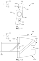
- FIG. 12 is a schematic side view of an embodiment of a blade actuating component
- FIG. 13 is a schematic isometric view of an embodiment of a blade
- FIG. 14 is a schematic isometric view of an embodiment of a blade
- FIG. 15 is a schematic view of an embodiment of a blade
- FIG. 16 is a schematic isometric view of an embodiment of a blade actuating component and two corresponding blades
- FIG. 17 is a schematic isometric view of the blade actuating component of FIG. 16 coupled with the two corresponding blades;
- FIG. 18 is a schematic isometric view of a superior side of a cover of an implant, according to an embodiment
- FIG. 19 is a schematic isometric view of an inferior side of the cover of FIG. 13 ;
- FIG. 20 is a schematic isometric view of an embodiment of a body and a cover for an implant
- FIG. 21 is a schematic isometric view of an embodiment of a body and a cover for an implant
- FIG. 22 is a schematic isometric view of an implant in a deployed position
- FIG. 23 is a schematic anterior-side view of an implant in a deployed position
- FIG. 24 is a schematic lateral-side view of an implant in a deployed position
- FIG. 25 is a schematic isometric view of an implant in an insertion position, including a cross-sectional view of several components, according to an embodiment
- FIG. 26 is a schematic isometric view of the implant of FIG. 25 in an intermediate position between the insertion position and the deployed position here, including a cross-sectional view of the several components;
- FIG. 27 is a schematic isometric view of the implant of FIG. 25 in a deployed position, including a cross-sectional view of the several components;
- FIG. 28 is a schematic isometric view of the implant of FIG. 25 in an intermediate position, including a cross-sectional view of the several components;
- FIG. 29 is a schematic isometric view of a locking screw according to an embodiment
- FIG. 30 is a schematic side view of the locking screw of FIG. 29 ;
- FIG. 31 is a schematic isometric view of an implant with a locking screw, according to an embodiment
- FIG. 32 is a schematic isometric view of an implant with a locking screw, according to an embodiment
- FIG. 33 is a schematic lateral-side view of a blade actuating component for an implant, according to another embodiment
- FIG. 34 is a cross-sectional view of an a body and a blade actuating component in the insertion position, according to another embodiment
- FIG. 35 is a cross-sectional view of an a body and a blade actuating component in the deployed position, according to another embodiment
- FIG. 36 is a schematic top-down view of an implant and an insertion tool.
- FIG. 37 is a schematic cross-sectional top-down view of the insertion tool with a representation of an implant of FIG. 36 .
- the embodiments described herein are directed to an implant for use in a spine.
- the embodiments include implants with a body and one or more blades.
- any embodiments may make use of any of the body/support structures, blades, actuating components or other structures disclosed in Duffield et al., U.S. Pat. No. 9,707,100, issued on Jul. 18, 2017 and titled “Interbody Fusion Device and System for Implantation,” Sack, U.S. Pat. No. 10,307,265, issued on Jun. 4, 2019 and titled “Implant With Deployable Blades,” and Duffield et al., U.S. Patent Publication Number 2017/0100260, published on Apr. 13, 2017 and titled “Insertion Tool For Implant And Methods of Use,” each of which are hereby incorporated by reference in their entirety.
- FIG. 1 is a schematic view of an embodiment of an implant 100 .
- implant 100 is shown adjacent to a depiction of a spinal column 102 in a human body 104 .
- FIG. 2 an embodiment of implant 100 is shown as it is being inserted into human body 104 with the use of an insertion tool 206 .
- implant 100 may also be referred to as a cage or fusion device.
- implant 100 is configured to be implanted within a portion of the human body.
- implant 100 may be configured for implantation into the spine.
- implant 100 may be a spinal fusion implant, or spinal fusion device, which is inserted between adjacent vertebrae to provide support and/or facilitate fusion between the vertebrae.
- spinal fusion implant or spinal fusion device, which is inserted between adjacent vertebrae to provide support and/or facilitate fusion between the vertebrae.
- FIG. 3 a section of spinal column 102 is illustrated, where implant 100 has been positioned between a first vertebra 192 and a second vertebra 194 .
- implant 100 is seen to include two blades (a first blade 241 and a second blade 242 ), which extend from the superior and inferior surfaces of implant 100 . Each of the blades has been driven into an adjacent vertebra (i.e., first vertebra 192 or second vertebra 194 ) so as to help anchor implant 100 .
- implant 100 may be inserted using an anterior lumbar interbody fusion (ALIF) surgical procedure, where the disc space is fused by approaching the spine through the abdomen.
- ALIF anterior lumbar interbody fusion
- implant 100 can be inserted through a small incision in the front or anterior side of the body.
- an anterior approach may afford improved exposure to the disc space to a surgeon. The anterior approach can allow a larger device to be used for the fusion, increasing the surface area for a fusion to occur and allowing for more postoperative stability.
- Insertion and placement of the disc along the front of a human body can also re-establish the patient's normal sagittal alignment in some cases, giving individuals a more normal inward curve to their low back.
- anterior refers to a side or portion of an implant that is intended to be oriented towards the front of the human body when the implant has been placed in the body.
- the term “posterior” refers to a side or portion of an implant that is intended to be oriented towards the back of the human body following implantation.
- the term “superior” refers to a side or portion of an implant that is intended to be oriented towards a top (e.g., the head) of the body while “inferior” refers to a side or portion of an implant that is intended to be oriented towards a bottom of the body.
- lateral sides or portions of an implant, which are sides or portions facing along a lateral direction of the body.
- FIG. 4 is a schematic isometric view of an embodiment of implant 100 , according to an embodiment.
- implant 100 is understood to be configured with an anterior side 110 and a posterior side 112 .
- Implant 100 may also include a first lateral side 114 and a second lateral side 116 .
- implant 100 may also include a superior side 130 and an inferior side 140 .
- distal refers to a part that is located further from a center of an implant
- proximal refers to a part that is located closer to the center of the implant.
- center of the implant could be the center of mass and/or a central plane and/or another centrally located reference surface.
- implant 100 may be associated with a longitudinal axis 120 that extends along the longest dimension of implant 100 between first lateral side 114 and second lateral side 116 . Additionally, implant 100 may be associated with a posterior-anterior axis 122 (also referred to as a “widthwise axis”) that extends along the widthwise dimension of implant 100 , between posterior side 112 and anterior side 110 . Moreover, implant 100 may be associated with a vertical axis 124 that extends along the thickness dimension of implant 100 and which is generally perpendicular to both longitudinal axis 120 and posterior-anterior axis 122 .
- An implant may also be associated with various reference planes or surfaces.
- the term “median plane” refers to a vertical plane which passes from the anterior side to the posterior side of the implant, dividing the implant into right and left halves, or lateral halves.
- the term “transverse plane” refers to a horizontal plane located in the center of the implant that divides the implant into superior and inferior halves.
- the term “coronal plane” refers to a vertical plane located in the center of the implant that divides the implant into anterior and posterior halves.
- the implant is symmetric or substantially symmetric about two planes, such as the median and the transverse plane.
- FIG. 5 is a schematic isometric exploded view of implant 100 according to an embodiment.
- implant 100 is comprised of a body 200 and a cover 220 , which together may be referred to as a housing 201 of implant 100 .
- a body and cover may be integrally formed.
- a body and cover may be separate pieces that are joined by one or more fasteners.
- body 200 and cover 220 are separate pieces that are fastened together using additional components of implant 100 .
- Embodiments of an implant may include provisions for anchoring the implant into adjacent vertebral bodies.
- an implant may include one or more anchoring members.
- implant 100 includes a set of blades 240 that facilitate anchoring implant 100 to adjacent vertebral bodies following insertion of implant 100 between the vertebral bodies.
- Set of blades 240 may be further comprised of first blade 241 and second blade 242 .
- the exemplary embodiments described herein include two blades, other embodiments of an implant could include any other number of blades. For example, in another embodiment, three blades could be used. In another embodiment, four blades could be used, with two blades extending from the inferior surface and two blades extending from the superior surface of the implant. Still other embodiments could include five or more blades. In yet another embodiment, a single blade could be used.
- An implant with blades can include provisions for moving the blades with respect to a housing of the implant.
- an implant includes a blade actuating component that engages with one or more blades to extend and/or retract the blades from the surfaces of the implant.
- implant 100 includes a blade actuating component 260 .
- blade actuating component 260 is coupled to first blade 241 and second blade 242 . Moreover, by adjusting the position of blade actuating component 260 within housing 201 , first blade 241 and second blade 242 can be retracted into, or extended from, surfaces of implant 100 .
- An implant can include provisions for locking the position of one or more elements of the implant.
- an implant can include provisions for locking the actuating component in a given position, thereby also locking one or more blades in a given position, such as through the use of a threaded fastener or other type of securing mechanism.
- implant 100 includes locking screw 280 .
- locking screw 280 can be used to lock blade actuating component 260 in place within implant 100 , which ensures first blade 241 and second blade 242 remain in an extended or deployed position, as will be shown further below.
- Embodiments can also include one or more fasteners that help attach a body to a cover.
- pins, screws, nails, bolts, clips, or any other kinds of fasteners could be used.
- implant 100 includes a set of pins 290 that help fasten cover 220 to body 200 .
- two pins are used, including first pin 291 and second pin 292 .
- any other number of pins could be used.
- a single pin could be used.
- three or more pins could be used.
- FIGS. 6 - 9 four views are presented of an embodiment of body 200 .
- FIG. 6 is a schematic isometric superior side or top-down isometric view of body 200 .
- FIG. 7 depicts a schematic isometric inferior side or bottom-up isometric view of body 200 .
- FIG. 8 is a schematic posterior or rear side view of body 200 .
- FIG. 9 is a schematic anterior or front side view of body 200 .
- body 200 may provide the posterior and anterior sides of housing 201 , as well as at least one lateral side of housing 201 .
- the lateral sides of a body may both have a lattice-like geometry.
- Various openings or apertures can help reduce the overall weight of the implant, and/or decrease manufacturing costs associated with material usage.
- openings can increase the surface area available throughout body 200 , and facilitate the application of bone growth promoting materials to the implant, and/or facilitate the coupling of the implant with the insertion tool, as will be discussed further below.
- the lateral sides could be configured as solid walls with one or more openings.
- openings in the housing of the implant there can be improved visual clarity regarding the degree or extent of blade deployment.
- body 200 has a generally oval cross-sectional shape in a horizontal plane.
- each of superior side 130 and inferior side 140 include at least one through-hole opening.
- implant 100 includes a first opening 610 and a second opening 612 .
- first opening 610 and second opening 612 extend continuously through the thickness of implant 100 from superior side 130 to inferior side 140 in a direction substantially aligned with vertical axis 124 . While the openings can vary in size, shape, and dimension in different embodiments, in one embodiment both first opening 610 and second opening 612 each have a generally half-circle or semi-circle cross-sectional shape along the horizontal plane.
- posterior side 112 and anterior side 110 of body 200 have a generally oblong rectangular shape.
- a sidewall 630 extends around the majority of perimeter of body 200 , extending between superior side 130 to inferior side 140 in a direction substantially aligned with vertical axis 124 , forming a periphery that surrounds or defines a majority of the outer surface of the implant.
- first lateral side 114 and second lateral side 116 are substantially similar (i.e., can include substantially similar structural features), though in other embodiments, each side can include variations.
- sidewall 630 can include a plurality of side openings or apertures, though in other embodiments, sidewall 630 can be substantially continuous or solid.
- first lateral side 114 includes a first aperture 480 , a second aperture 482 , a third aperture 484 , a fourth aperture 486 , a fifth aperture 488 , and a sixth aperture 490 .
- Each aperture can differ in shape in some embodiments.
- first aperture 480 has a substantially oblong rectangular shape
- second aperture 482 has a five-sided or substantially pentagonal shape
- third aperture 484 and fifth aperture 488 each have a four-sided or substantially trapezoidal shape
- fourth aperture 486 has a substantially round shape
- sixth aperture 490 has a six-sided or substantially hexagonal shape.
- second lateral side 116 can include a fewer or greater number of apertures.
- second lateral side 116 can also include a plurality of apertures disposed in a similar arrangement as first lateral side 114 in some embodiments.
- the shapes of the various openings are configured to permit the implant body to be manufactured in the Direct Metal Laser Sintering (DMLS) process, as well as to provide support to the inferior and superior load bearing surfaces.
- DMLS Direct Metal Laser Sintering
- anterior side 110 of body 200 includes guide opening 222 .
- Guide opening 222 extends through the thickness of sidewall 630 in a direction substantially aligned with posterior-anterior axis 122 .
- Guide opening 222 includes a chamber portion (“chamber”) 492 and a hollow grooved portion (the hollow grooved portion will be discussed further below with respect to FIGS. 31 and 32 ).
- Chamber 492 can be understood to be connected with the grooved portion such that some components can pass from chamber 492 into the grooved portion (or vice versa).
- a portion of blade actuating component 260 can be configured to extend through or be received by the chamber portion.
- the chamber portion can be sized and dimensioned to fit or extend closely around a portion of blade actuating component 260 .
- chamber 492 comprises a generally oblong four-sided opening.
- chamber 492 has a substantially oblong square or rectangular cross-sectional shape in a vertical plane.
- chamber 492 extends between an outwardly-facing or distally oriented surface 685 of sidewall 630 and an inwardly-facing or proximally oriented surface 695 of sidewall 630 .
- the cross-sectional shape of the chamber portion is configured to prevent rotation of the driven shaft portion when the drive shaft portion is inserted into the chamber portion.
- Body 200 can also include additional reinforcement structures.
- body 200 includes a first inner sidewall 634 extending in a direction substantially aligned with posterior-anterior axis 122 and a second inner sidewall 636 extending in a direction substantially aligned with posterior-anterior axis 122 .
- First inner sidewall 634 and second inner sidewall 636 can be substantially parallel in one embodiment.
- different portions of body 200 can include recessed areas or apertures.
- first inner sidewall 634 and/or second inner sidewall 636 include a plurality of apertures 645 .
- first inner sidewall 634 and second inner sidewall 636 can help define or bound a central hollow region 638 in body 200 .
- Central hollow region 638 can extend through the thickness of body 200 .
- Central hollow region 638 can be configured to receive the blades and the blade actuating component, as will be discussed further below.
- FIGS. 6 and 7 it can be seen that central hollow region 638 includes a main opening 640 and a posterior opening 642 , where main opening 640 is connected with a posterior opening 642 such that some components can pass from main opening 640 into posterior opening 642 .
- Main opening 640 is located toward a center or middle portion of the body, and posterior opening 642 is located along the posterior periphery of the body.
- posterior opening 642 is significantly narrower in width across the horizontal plane relative to the width associated with main opening 640 .
- posterior opening 642 can be disposed between a first end portion 696 and a second end portion 698 that are associated with posterior side 112 of body 200 .
- each end portion can include a recessed region.
- a first posterior recess 692 is formed within a portion of first end portion 696 and a second posterior recess 694 is formed within a portion of second end portion 698 .
- first posterior recess 692 and second posterior recess 694 can be configured to receive a cover.
- First end portion 696 and a second end portion 698 can be substantially similar in some embodiments.
- first end portion 696 and a second end portion 698 are mirror-images of one another relative to a central posterior-anterior axis or midline.
- first posterior recess 692 and second posterior recess 694 are sized and dimensioned to snugly receive a rearward cover or cap that extends between or bridges together first end portion 696 and second end portion 698 of body 200 , providing a substantially continuous outer periphery of the implant.
- first end portion 696 and second end portion 698 can include pin holes (shown in FIG. 5 as pin holes 202 ), which can be used to help secure the cover to the posterior side of body 200 (see FIGS. 20 - 21 ).
- the configuration of body 200 shown for the embodiment of FIGS. 6 - 9 may facilitate the manufacturing process in different embodiments.
- this configuration may permit 3D Printing via laser or electron beam with minimal support structures by forming a unitary piece with a plurality of openings.
- This design may also help to improve visibility of adjacent bony anatomy under X-ray fluoroscopy while still providing sufficient structural support and rigidity to withstand all testing requirements and the clinical loading of an implant.
- Other embodiments, not pictured in the figures, include round or rectangular openings in otherwise solid geometry of the anterior, posterior, or lateral sides.
- Embodiments can also include one or more blade retaining portions.
- a blade retaining portion may receive any part of a blade, including one or more edges and/or faces of the blade.
- a body includes blade retaining portions to receive the anterior and posterior edges of each blade.
- body 200 includes a first blade retaining portion 600 positioned toward anterior side 110 of first inner sidewall 634 and a second blade retaining portion 602 positioned toward posterior side 112 of first inner sidewall 634 .
- each blade retaining portion is formed in an outer perimeter of a lateral side of main opening 640 of central hollow region 638 .
- First blade retaining portion 600 comprises a first blade retaining channel extending through the depth of body 200 that is configured to receive an anterior edge of the first blade (see FIG. 13 ).
- second blade retaining portion 602 comprises a second blade retaining channel extending through the depth of body 200 that is configured to receive a posterior edge of the first blade (see FIG. 13 ).
- one or more channels can be oriented in a direction that is substantially diagonal relative to the horizontal plane.
- a channel can be oriented approximately 45 degrees relative to the horizontal plane.
- a channel can be oriented vertically (approximately 90 degrees relative to the horizontal plane) or can be oriented between 30 degrees and 90 degrees relative to the horizontal plane.
- the orientation of a channel can be configured to correspond to the orientation of the anterior edges and/or posterior edges of a blade in some embodiments.
- Body 200 also includes third blade retaining portion 604 and fourth retaining portion 606 for receiving the anterior and posterior edges of the second blade.
- This configuration may help maximize available bone graft volume within the implant since the lateral edges of the blades serve as tracks for translation. Specifically, this limits the need for additional track members on the blade that would take up additional volume in the implant.
- the arrangement of the retaining channels and the associated blade edges results in most of the volume of the retaining channels being filled by the blade edges in the retracted position, which helps prevent any graft material or BGPM (details on the effect and use of bone growth promoting material will be discussed further below) from entering the retaining channels and inhibiting normal blade travel.
- BGPM graft material
- FIG. 10 is an isometric side view of an embodiment of blade actuating component 260 .
- a front or anterior side view of blade actuating component 260 is also shown in FIG. 11
- a lateral side view of blade actuating component 260 is depicted in FIG. 12 .
- blade actuating component 260 may include a driven shaft portion 320 and a blade engaging portion 322 .
- Driven shaft portion 320 further includes a driven end 262 along the anterior-most end of driven shaft portion 320 .
- driven end 262 can include one or more engaging features.
- driven shaft portion 320 can include a threaded opening 267 that is accessible from driven end 262 , as best seen in FIG. 10 .
- threaded opening 267 may receive a tool with a corresponding threaded tip.
- driven end 262 can be temporarily mated with the end of a tool (see FIG. 37 ) used to impact blade actuating component 260 and drive the set of blades into adjacent vertebrae. This may help keep both the driving tool and driven end 262 aligned during the impact, as well as reduce the tendency of the driving tool to slip with respect to driven end 262 .
- Using mating features also allows driven end 262 to be more easily “pulled” distally from implant 100 , which can be used to retract the blades, should it be necessary to remove the implant or re-position the blades.
- driven shaft portion 320 can be substantially elongated and/or narrow relative to blade engaging portion 322 .
- driven shaft portion 320 is seen to comprise a substantially elongated rectangular prism.
- driven shaft portion 320 has a substantially rounded rectangular cross-sectional shape in the vertical plane.
- blade engaging portion 322 has a greater width in the direction aligned with vertical axis 124 , and includes a generally rectangular shape with a U-shaped or wrench shaped posterior end.
- the size and shape of blade actuating component 260 allows driven shaft portion 320 to smoothly insert into the guide opening formed in of the body (see FIG. 6 ) while blade engaging portion 322 is shaped and sized to be positioned in the central opening of the body (see FIG. 7 ) and configured to receive the blade set.
- blade actuating component 260 includes provisions for securing or receiving a portion of the cover within the implant.
- blade actuating component 260 includes an actuating posterior end 1200 , which includes a receiving portion 1210 .
- Receiving portion 1210 can be sized and dimensioned to receive, fit, or be disposed around a portion of the cover in some embodiments.
- receiving portion 1210 comprises a mouth 1220 with two prongs that are spaced apart from one another along vertical axis 124 . In some cases, the two prongs can be spaced apart by a width that is substantially similar to the thickness of the cover.
- a blade actuating component can include provisions for coupling with one or more blades.
- a blade actuating component can include one or more channels.
- blade engaging portion 322 includes a first channel 350 and a second channel 352 .
- First channel 350 may be disposed in a first side surface 334 of blade actuating component 260 while second channel 352 may be disposed in a second side surface 336 of blade actuating component 260 .
- blade engaging portion 322 is oriented diagonally with respect to vertical axis 124 .
- a superior end 342 of blade engaging portion 322 is offset with respect to an inferior end 344 , such that the two ends are not aligned relative to vertical axis 124 when viewed from the anterior side of the component. In some embodiments, this can allow first channel 350 and second channel 352 to be approximately aligned in the vertical direction.
- FIG. 13 is a schematic isometric view of a distal face 408 of first blade 241
- FIG. 14 is a schematic isometric view of a proximal face 410 of first blade 241
- FIG. 15 depicts an inferior side 1330 of first blade 241
- First blade 241 or simply blade 241 , includes an outer edge 400 associated with inferior side 1330 of blade 241 , an inner edge 402 associated with a superior side 1340 , an anterior edge 404 and a posterior edge 406 .
- distal face 408 i.e., a face oriented in the outwardly-facing or distal direction
- proximal face 410 i.e., a face oriented in the inwardly-facing or proximal direction
- a blade could vary.
- a blade could have a substantially planar geometry such that the distal face and the proximal face of the blade are each parallel with a common plane, as best shown in FIG. 15 .
- a blade could be configured with one or more bends.
- a blade can have a channel-like geometry (ex. “C”-shaped or “S”-shaped).
- blade 241 has a U-shaped geometry with flanges. In particular, blade 241 a first channel portion 420 , a second channel portion 422 and a third channel portion 424 .
- first channel portion 420 is angled with respect to second channel portion 422 at a first bend 430 .
- third channel portion 424 is angled with respect to second channel portion 422 at second bend 432 .
- blade 241 includes a first flange 440 extending from first channel portion 420 at a third bend 434 .
- Blade 241 also includes a second flange 442 extending from third channel portion 424 at a fourth bend 436 . This geometry for blade 241 helps provide optimal strength for blade 241 compared to other planar blades of a similar size and thickness, and allowing for greater graft volume.
- blade 241 can include provisions for increasing the support or structural strength of blade 241 .
- blade 241 includes a bridge portion 1350 that is disposed or formed on distal face 408 . Referring to FIG. 13 , bridge portion 1350 extends between third bend 434 and fourth bend 436 . Bridge portion 1350 can be configured to increase the structural support of blade 2412 .
- bridge portion 1350 can include features that provide a truss, brace, buttress, strut, joist, or other type of reinforcement to the curved or undulating structure of blade 241 . In one embodiment, bridge portion 1350 is disposed nearer to the inner edge relative to the outer edge, such that bridge portion 1350 is offset relative to the distal face of the blade.
- bridge portion 1350 includes a relatively wide U-shaped or curved V-shaped outer sidewall 1370 .
- outer sidewall 1370 extends between third bend 434 and fourth bend 436 .
- bridge portion 1350 can have an inner sidewall (disposed on the opposite side of the bridge portion relative to the outer sidewall) that is disposed flush or continuously against the distal surfaces of first channel portion 420 , second channel portion 422 , and third channel portion 424 , represented in FIG. 13 by a U-shaped edge 1380 .
- the U-shape associated with the inner sidewall or edge of bridge portion 1350 is substantially similar to the U-shape geometry of blade 241 .
- Bridge portion 1350 can also be substantially symmetrical in some embodiments.
- bridge portion 1350 comprises a first triangular prism portion 1310 joined to a second triangular prism portion 1320 by a central curved portion.
- Each portion can bolster the structure of the blade, and provide resistance against the pressures applied to a blade by external forces during use of the implant.
- bridge portion 1350 can improve the ability of blade 241 to resist external pressures and forces and/or help maintain the specific shape of blade 241 .
- the outer edge 400 is a penetrating edge configured to be implanted within an adjacent vertebral body.
- outer edge 400 may be sharpened so that blade 241 has an angled surface 409 adjacent outer edge 400 .
- anterior edge 404 and posterior edge 406 are also sharpened in a similar manner to outer edge 400 and may act as extensions of outer edge 400 to help improve strength and penetration.
- bridge portion 1350 can also serve to help prevent the blades from extending further outward into a vertebrae downward once they reach the desired deployment extension.
- a blade can further include provisions for coupling with a blade actuating component.
- a blade can include a protruding portion.
- the protruding portion can extend away from a face of the blade and may fit within a channel in a blade actuating component.
- blade 241 includes a protruding portion 450 that extends from proximal face 410 .
- Protruding portion 450 may generally be sized and shaped to fit within a channel of the blade actuating component (i.e., first channel 350 shown in FIG. 11 ).
- the cross-sectional shape may fit within a channel of the blade actuating component.
- the cross-sectional width of protruding portion 450 may increase between a proximal portion 452 and a distal portion 454 allowing protruding portion 450 to be interlocked within a channel as discussed in detail below.
- a protruding portion may be oriented at an angle on a blade so as to fit with an angled channel in a blade actuating component.
- protruding portion 450 may be angled with respect to inner edge 402 such that the body of blade 241 is vertically oriented within the implant when protruding portion 450 is inserted within the first channel.
- the longest dimension of protruding portion 450 may form a protruding angle 459 with inner edge 402 .
- second blade 242 may have a substantially identical geometry to first blade 241 .
- orientation of the second blade can differ such that the inner edge is associated with the inferior side and the outer edge is associated with the superior side.
- each blade may be associated with the blade engaging portion of the blade actuating component.
- FIG. 16 an exploded isometric view is shown with blade actuating component 260 , first blade 241 , and second blade 242 , and in FIG. 17 , first blade 241 and second blade 242 are assembled within blade actuating component 260 .
- protruding portion 450 of first blade 241 fits into first channel 350 .
- protruding portion 455 of second blade 242 fits into second channel 352 .
- blade engaging portion 322 may comprise a superior surface 330 , an inferior surface 332 , a first side surface 334 , and a second side surface 336 .
- first side surface 334 may be a first lateral side facing surface
- second side surface 336 may be a second lateral side facing side surface.
- first channel 350 has a first end 354 open along superior surface 330 and a second end 356 open along inferior surface 332 .
- first end 354 is disposed further from driven shaft portion 320 than second end 356 .
- second channel 352 includes opposing ends on superior surface 330 and inferior surface 332 , though in this case the end disposed at superior surface 330 is disposed closer to driven shaft portion 320 than the end disposed at inferior surface 332 .
- the angle of each channel could be selected to provide proper blade extension for varying implant sizes.
- the angle of a channel is defined to be the angle formed between the channel and a transverse plane of the blade actuating component.
- first channel 350 forms a first angle with transverse plane 370 of blade actuating component 260
- second channel 352 forms a second angle with transverse plane 370 .
- the first angle and the second angle are equal to provide balanced reactive forces as the blades are deployed.
- each blade is deployed about a centerline (e.g., transverse plane 370 ) of the blade actuating component, which helps minimize friction and binding loads between these parts during blade deployment. Additionally, the arrangement helps provide balanced reaction forces to reduce insertion effort and friction.
- the angle of each channel could vary. In some embodiments, a channel could be oriented at any angle between 15 and 75 degrees. In other embodiments, a channel could be oriented at any angle between 35 and 65 degrees. Moreover, in some embodiments, the angle of a channel may determine the angle of a protruding portion in a corresponding blade. For example, protruding angle 459 formed between protruding portion 450 and inner edge 402 of blade 241 (see FIG. 14 ) may be approximately equal to the angle formed between first channel 350 and transverse plane 370 . This keeps the outer penetrating edge of blade 241 approximately horizontal so that the degree of penetration does not vary at different sections of the blade.
- each channel has a cross-sectional shape that facilitates a coupling or fit with a corresponding portion of a blade.
- channel 350 has an opening 355 on first side surface 334 with an opening width 390 .
- channel 350 has a width 392 that is greater than opening width 390 .
- This provides a cross-sectional shape for channel 350 that allows for a sliding joint with a corresponding part of first blade 241 .
- first channel 350 and second channel 352 are configured with dovetail cross-sectional shapes.
- blade engaging portion 322 may be contoured at the superior and inferior surfaces to resist subsidence and allow maximum blade deployment depth. This geometry may also help to keep the blade engaging portion 322 centered between vertebral endplates. As an example, the contouring of superior surface 330 and inferior surface 332 in the present embodiment is best seen in the enlarged cross-sectional view of FIG. 17 .
- first channel 350 may be associated with a first channel direction 460 that is directed towards superior surface 330 along the length of first channel 350 .
- first channel 350 includes a second channel direction 462 that is directed towards inferior surface 332 along the length of first channel 350 .
- first protruding portion 450 of first blade 241 can slide in first channel direction 460 or second channel direction 462 .
- first blade 241 moves vertically with respect to blade actuating component 260 such that first blade 241 extends outwardly on a superior side of the implant to a deployed position (see FIGS. 26 - 27 ).
- first blade 241 moves vertically with respect to blade actuating component 260 such that first blade 241 is retracted within housing 201 of implant 100 (see FIG. 28 ).
- second protruding portion 455 of second blade 242 may slide in first and second channel directions of second channel 352 such that second blade 242 can be extended and retracted from implant 100 on an inferior side (see FIGS. 25 - 28 ).
- blade actuating component 260 propels both blades in opposing directions thereby balancing the reactive loads and minimizing cantilevered loads and friction on the guide bar.
- first blade 241 can translate along first channel direction 460 or second channel direction 462 , but may not move in a direction 465 that is perpendicular to first channel direction 460 and second channel direction 462 (i.e., blade 241 cannot translate in a direction perpendicular to the length of first channel 350 ).
- first channel 350 and first protruding portion 450 are such that first protruding portion 450 cannot fit through the opening in first channel 350 on first side surface 334 of blade actuating component 260 .
- each protruding portion forms a sliding dovetail connection or joint with a corresponding channel.
- Using dovetail tracks on the blade actuating component and corresponding dovetail features on the posterior and anterior blades allows axial movement along the angle of inclination while preventing disengagement under loads encountered during blade impaction and retraction.
- first protruding portion 450 forms a sliding dovetail joint with first channel 350 .
- the embodiments are not limited to dovetail joints and other fits/joints where the opening in a channel is smaller than the widest part of a protruding portion of a blade could be used.
- a blade could comprise one or more channels and a blade actuating component could include corresponding protrusions to fit in the channels.
- both the protruding portion of the blade actuating component and the channels in the blades could have corresponding dovetail geometries.
- embodiments of implant 100 can include a cover 220 that is configured to close or bridge the posterior opening of body 200 and help secure the various components of implant 100 together.
- FIG. 18 is a schematic isometric superior-side view of an embodiment of cover 220
- cover 220 includes one or more openings for engaging different parts of implant 100 .
- cover 220 may include a first pin hole 227 and a second pin hole 228 that are configured to receive a first pin and a second pin, respectively (see FIG. 5 ).
- Each pin hole can comprise a through-hole that extends from the superior surface to the inferior surface of cover 220 , though in other embodiments pin holes can be blind holes.
- first pin hole 227 and second pin hole 228 (shown in FIGS. 18 and 19 ) of cover 220 may be aligned with corresponding holes in the body, as discussed below.
- FIG. 20 is a schematic isometric exploded view of body 200 and cover 220 .
- FIG. 21 is a schematic isometric assembled view of body 200 and cover 220 , together forming housing 201 of implant 100 .
- cover 220 can be inserted into the recesses associated with a posterior end 2000 of body 200 .
- first pin hole 227 and second pin hole 228 shown in FIG. 20 can be aligned with the pin receiving openings of body 200 comprising between two and four through-hole channels in posterior end 2000 .
- first end portion 696 includes a third pin hole 2030 in a superior portion of first end portion 696 and a fourth pin hole 2040 in an inferior portion of first end portion 696 .
- second end portion 698 includes a fifth pin hole 2050 in a superior portion of second end portion 698 and a sixth pin hole 2060 in an inferior portion of second end portion 698 .
- third pin hole 2030 and the fourth pin hole are aligned with the first pin hole of cover 220
- fifth pin hole 2050 and the sixth pin hole are aligned with the second pin hole of cover 220 .
- body 200 may only include third pin hole 2030 and fifth pin hole 2050 , for example.
- the embodiments described herein provide an implant that can move from a first position (the “insertion position”), which allows the implant to maintain a low profile, to a second position (the “impaction position” or the “deployed position”), that deploys the blades and inserts them into the proximal superior and inferior vertebral bodies.
- the blades of the device While the implant is in the first (insertion) position, the blades of the device may be retracted within the body of the implant (i.e., the blades may themselves be in a “retracted position”).
- the blades In the second (deployed) position of the implant, the blades extend superiorly (or cranially) or inferiorly (or caudally) beyond the implant and into the vertebral bodies to prevent the implant from moving out of position over time.
- the blades themselves may be said to be in an “extended position” or “deployed position”.
- the implant resists left to right rotation and resists flexion and/or extension.
- the blades may approximately move in vertical directions (i.e., the superior and inferior directions), the actual direction of travel may vary from one embodiment to another.
- the blades may be slightly angled within the implant and may deploy at slight angles relative to a vertical direction (or to the inferior/superior directions).
- FIGS. 4 , 21 , and 22 - 24 illustrate several views of implant 100 in different operating modes or operating positions.
- FIG. 4 is a schematic isometric anterior side view of implant 100 in an insertion position.
- FIG. 21 is a schematic isometric posterior side view of implant 100 in the same insertion position of FIG. 4 .
- driven end 262 of blade actuating component 260 may be disposed distal to the chamber portion of body 200 (i.e., a portion of blade actuating component 260 is disposed or extends through the chamber portion).
- first blade 241 and second blade 242 are retracted within housing 201 .
- first blade 241 or second blade 242 extend outwardly (distally) from superior side 130 or inferior side 140 , respectively, of implant 100 .
- implant 100 In this insertion position, implant 100 has a compact profile and can be more easily maneuvered into place in the excised disc space between adjacent vertebrae.
- FIG. 22 is a schematic isometric view of implant 100 in a deployed position.
- FIG. 23 is a schematic anterior side view of implant 100 in the same deployed position of FIG. 22 .
- FIG. 24 is a schematic lateral side view of implant 100 in the same deployed position of FIG. 23 .
- driven end 262 of blade actuating component 260 may be disposed proximally to an anterior opening 2250 formed in the outer periphery of body 200 (i.e., the entirety of blade actuating component 260 is disposed within implant 100 ).
- first blade 241 and second blade 242 are extended outwards from superior side 130 and inferior side 140 , respectively, so as to be inserted into adjacent vertebral bodies.
- each blade remains positioned in the central hollow region of the body in both the retracted and extended positions.
- an inner edge of each blade is disposed in a central hollow region of the housing in the retracted position, and the inner edge of the blade remains in the central hollow region in the extended position.
- one or more blades could be deployed at a slight angle, relative to the normal directions on the superior and inferior surfaces of the implant. In some embodiments, one or more blades could be oriented at an angle between 0 and 30 degrees. In other embodiments, one or more blades could be oriented at an angle that is greater than 30 degrees.
- first blade 241 and second blade 242 are both oriented at a slight angle from normal axis 251 . Specifically, first blade 241 forms a first angle 250 with normal axis 251 and second blade 242 forms a second angle 252 with normal axis 251 . In one embodiment, first angle 250 and second angle 252 are both approximately 10 degrees.
- the common anterior implant blade angle is chosen to keep the blades close to the centerline of the vertebral body to minimize rotational loads on the vertebral bodies during blade deployment and also to provide an optional cover plate screw clearance.
- the outer edge of each blade is positioned toward a central region of the implant when the blade is deployed, such that the outer edge is positioned centrally relative to the housing in the extended position.
- first blade 241 and second blade 242 combined may be coverable of extending outwardly from implant 100 by an amount equal to 110% of the depth of implant 100 . This can be done while still keeping the blades fully retracted within implant 100 since the blades are guided by two robust parallel tracks in body 200 and also by angled cross channels in blade actuating component 260 , thus constraining all six axes of motion.
- the combined blade height at deployment could be less than 100%.
- the implant could be designed so that the combined blade height is less than 10 mm to reduce the risk of fracturing the adjacent vertebral bodies.
- the implant has a combined blade height of 6 mm or less.
- implant 100 can use a three-point attachment configuration for each of first blade 241 and second blade 242 .
- each blade is received along its lateral edges by two blade retaining portions, and also coupled to blade actuating component 260 using the dovetail connection described above.
- anterior edge 404 of first blade 241 is received within the first blade retaining channel of first blade retaining portion 600 .
- Posterior edge 406 of first blade 241 is received within a second retaining channel of second blade retaining portion 602 .
- distal face 408 of first blade 241 remains unattached to any other elements of implant 100 .
- first blade 241 remains unattached along distal face 408 , but the entirety of distal face 408 between anterior edge 404 and posterior edge 406 is spaced apart from (i.e., not in contact with) all other elements of implant 100 .
- second blade 242 is likewise attached at its lateral edges to corresponding blade retaining portions and also coupled to blade actuating component 260 using a sliding dovetail connection.
- first blade 241 and second blade 242 are held in implant 100 using a three-point attachment configuration that may limit unwanted friction on first blade 241 and second blade 242 during impaction.
- the fit between each blade and each blade retaining channel may provide sufficient clearance to allow for translation of the blades along the retaining channels. In other words, the fit may not be so tight as to impede movement of the lateral edges within the retaining channels.
- first blade retaining portion 600 (see FIG. 22 ) has a rectangular blade retaining channel. This rectangular geometry for the blade tracks or channels and tolerance allows for precise axial travel without binding from actuation ramp angular variations.
- the posterior edge and anterior edge of each blade may remain in the tracks or channels of each blade retaining portion while the blades are retracted to prevent bone graft material from restricting free deployment of the blades.
- an interlocking joint such as a dovetail sliding joint
- a blade actuating component helps prevent the blades from decoupling from the blade actuating component during impact. Additionally, with an interlocking joint the blade actuating component can be used to retract the blades.
- FIGS. 25 - 28 illustrate several schematic views of implant 100 during an impact sequence ( FIGS. 25 - 27 ) as well as during a step of retracting the blades ( FIG. 28 ).
- housing 201 of implant 100 is shown in phantom to better show blade actuating component 260 , first blade 241 and second blade 242 .
- FIGS. 25 - 28 include cross-sectional views of a section of blade actuating component 260 , first blade 241 and second blade 242 to better illustrate the coupling between these parts during actuation.
- implant 100 is in the insertion position, with first blade 241 and second blade 242 fully retracted within housing 201 .
- an impacting force 700 is applied to driven end 262 of blade actuating component 260 .
- blade actuating component 260 applies forces to first blade 241 and second blade 242 along first channel 350 and second channel 352 , respectively.
- the orientation of first channel 350 is such that first blade 241 is forced towards the inferior side of implant 100 .
- the orientation of second channel 352 is such that second blade 242 is forced towards the superior side of implant 100 .
- the channel orientations can be switched such that first blade 241 is forced towards the inferior side of implant 100 and second blade 242 is forced towards the superior side of implant 100 .
- first protruding portion 450 and first channel 350 (as well as between second protruding portion 455 and second channel 352 ) means that both blades remain coupled to the motion of blade actuating component 260 at all times. It should be noted that since both blades are restricted from moving in a longitudinal direction, the resulting motion of each blade is purely vertical. Moreover, using the dovetail shaped protruding portions for each blade means the protruding portions are both lifting at the center line to limit any cocking force or rotational moments that could result in increased (friction) resistance to motion or binding of these moving parts.
- the forces deploying the blades are balanced through the blade actuating component 260 in order to minimize friction and binding between driven shaft portion 320 and the guide opening in body 200 (see FIG. 6 ), which helps to guide blade actuating component 260 and keep its motion restricted to directions parallel to the longitudinal axis (see FIG. 2 ).
- FIG. 27 implant 100 has been placed in the fully deployed position, with both first blade 241 and second blade 242 fully extended from implant 100 . As seen in the cross-sectional view, both first blade 241 and second blade 242 remain coupled with blade actuating component 260 when implant 100 is in the fully deployed position. Because of this coupling, the motion of blade actuating component 260 can be reversed to retract first blade 241 and second blade 242 , as shown in FIG. 28 .
- a blade actuating component may function to support adjacent vertebral bodies. This is can be accomplished by using a blade actuating component with a height similar to the height of the outer support structure so that the superior and inferior surfaces of the blade actuating component may come into contact with the vertebral bodies following implantation. Since the blade actuating component functions as a load bearing structure within the implant, this may free up additional space in the implant otherwise occupied by additional support structures, thereby increasing the internal volume available for bone graft or BGPMs.
- driven end 262 of blade actuating component 260 may be pulled in an opposing direction to the motion shown in FIG. 26 .
- a delivery tool can be coupled to driven end 262 using a threaded connector. Then, as the tip of the delivery tool is retracted a retracting or pulling force 710 may be applied to drive end 262 .
- blade actuating component 260 (and specifically, blade engaging portion 322 ) is pulled towards anterior side 110 of implant 100 , blade actuating component 260 applies forces to first blade 241 and second blade 242 along first channel 350 and second channel 352 , respectively.
- the orientation of first channel 350 is such that first blade 241 is forced towards the superior side of implant 100 .
- second channel 352 is such that second blade 242 is forced towards the inferior side of implant 100 .
- applying sufficient force at driven end 262 may result in full retraction of first blade 241 and second blade 242 so that implant 100 is returned to the insertion position shown in FIG. 25 .
- body 200 may include guide opening 222 that receives a portion of blade actuating component 260 .
- the driven shaft portion can be disposed securely in the chamber portion.
- the chamber portion of guide opening 222 may have a shape that matches the cross-sectional shape of a driven shaft portion of a blade actuating component.
- both the chamber portion and the driven shaft portion of the blade actuating component have rectangular cross-sectional shapes (see FIGS. 9 and 11 ). This configuration may allow axial motion, but control rotational and angular loads that could result during blade impaction.
- FIGS. 29 and 30 illustrate two schematic views of locking screw 280 , according to an embodiment.
- Locking screw 280 can be a type of threaded fastener in some embodiments.
- locking screw 280 includes a flanged head 282 with a threaded segment portion 284 and further includes a substantially smooth and elongated body portion 288 .
- Threaded segment portion 284 is sized and dimensioned to engage with the grooved portion of the body (see FIG. 33 below).
- Flanged head 282 can also include a receiving recess 2900 which can engage with a driving tool in order to secure the locking screw within the implant.
- body portion 288 is disposed within threaded opening of the blade actuating component when the screw lock is secured, body portion 288 need not engage or lock with the threading associated with the threaded opening.
- Implant 100 can include provisions for securing the implant 100 in the deployed position.
- guide opening 222 can include a grooved portion 3100 that is formed directly adjacent to the chamber portion.
- Grooved portion 3100 can have a round cross-sectional shape in the vertical plane, and has a wider diameter relative to the diameter or width of the chamber portion.
- the diameter of grooved portion 3100 can be configured to mate with the diameter of the flanged head.
- grooved portion 3100 is disposed directly adjacent to the outermost anterior periphery of guide opening 222 . As locking screw 280 is inserted into the anterior side of guide opening 222 (see FIG.
- threaded segment portion 284 that extends around flanged head 282 of locking screw 280 can engage with grooved portion 3100 , securing locking screw 280 to body 200 .
- body portion 288 of locking screw 280 can also be disposed through the passageway of threaded opening 267 of blade actuating component 260 .
- a portion of driven shaft portion 320 is disposed within chamber 492 of guide opening 222 , primarily comprising the portion of driven shaft portion 320 that includes threaded opening 267 .
- flanged head 282 of locking screw 280 extends from anterior opening 2250 through grooved portion 3100 , and body portion 288 of locking screw 280 extends through threaded opening 267 of driven shaft portion 320 .
- Flanged head 282 is prevented from moving further into guide opening 222 because of the larger diameter of flanged head 282 relative to body portion 288 .
- an implant can utilize different types of components to provide the features and functions described herein.
- the features of blade actuating component can be adjusted in order to facilitate the use of implant with a variety of surgical requirements.
- an alternate embodiment of a second blade actuating component (“second actuating component”) 3300 can be placed within the housing of the body, as shown in FIG. 33 .
- second actuating component 3300 is configured with a receiving portion 3350 with a mouth 3320 that is greater in width than the embodiment of the actuating blade component presented above.
- Adjustments to the size of a mouth in the receiving portion of a blade actuating component can correspond to changes in the dimensions or shape of a cover, bridge piece, or cap that is used in the implant.
- the height and/or other dimensions of the blade engaging portion can be increased or decreased.
- blade actuating component 260 has a first maximum height 1230
- second actuating component 3300 has a second maximum height 3330 .
- First maximum height 1230 is less than second maximum height 3330 , such that blade actuating component 260 can be inserted into a smaller region of the human body.
- the greater height of second actuating component 3300 provides the structural support to the device.
- second actuating component 3300 includes diagonal portions 3340 disposed toward the center of the actuating component that can extend the length of channels 3310 and support additional blade weight.
- diagonal portions 3340 are integrally formed with second actuating component 3300 .
- diagonal portions 3340 can add a curved or sloped interface to the actuating component relative to blade actuating component described earlier (see FIG. 12 ) in which the intersection between drive shaft portion 320 and blade engaging portion 322 is substantially perpendicular.
- FIGS. 34 and 35 provide two cross-sectional views of the implant prior to the application of an impacting force (see FIG. 26 ) and subsequent to the application of the impacting force. It should be noted that while FIGS. 34 and 35 employ second actuating component 3300 , the general operation and transition from insertion to deployment of implant 100 remains substantially the same to the process described above with respect to blade actuating component 260 . In FIG. 34 , second actuating component 3300 is disposed such that driven end 262 extends distally outward and away from an anterior end 3400 of body 200 .
- second actuating component 3300 is positioned such that it is offset relative to the interior space of the implant along posterior-anterior axis 122 .
- the majority of blade engaging portion 322 is disposed nearer to anterior end 3400 than to posterior end 2000 of body 200 in the insertion position.
- second actuating component 3300 can be disposed within the internal space of the body.
- actuating posterior end 1200 can move translationally from the main opening of the central hollow region in body 200 toward the posterior opening. It can be seen that a portion of posterior opening 642 is filled with or bridged by a central portion of cover 220 . As actuating posterior end 1200 approaches the posterior opening, receiving portion 1210 comprising the two-pronged mouth shown in FIG. 33 can slide or be positioned above the superior surface and below the inferior surface of cover 220 , helping to secure the assembly in place and forming a continuous outer surface.
- threaded opening 267 of driven shaft portion 320 can be configured to receive a threaded driving tool.
- threaded flanged head 282 of the locking screw engages with grooved portion 3100 formed in the structure of body 200 , and the locking screw body is smoothly inserted within the channel provided by threaded opening 267 .
- Driven end 262 can be positioned directly adjacent to the posterior end of grooved portion 3100 when implant 100 is in the deployed position. In other words, once implant 100 is in the deployed position, driven end 262 is disposed such that it is spaced apart from the outer opening formed in body 200 by the region comprising grooved portion 3100 .
- implant 100 can make use of features or structures disclosed in the “Insertion Tool For Implant And Methods of Use” application.
- implant 100 can be configured for use with a single tool that can significantly facilitate the implantation process. For example, whether a surgeon approaches the disc space from an anterior approach can be dependent on how comfortable the surgeon is with the anterior approach and operating around the aorta and vena cava. By approaching a patient from the anterior side, there can be a risk of vessel injury, as the aorta and vena cava lie in front of the spine. However, the benefits of added stability and fusion area very often outweigh the risks of the extra surgery, and the process of deployment provided herein can help lower such risks.
- body 200 may include attachment points for an insertion instrument.
- a portion of an insertion tool 3600 is shown with implant 100 .
- insertion tool 3600 is shown as it holds or grasps implant 100 .
- FIG. 37 the same view of FIG. 36 is shown in a partial cross-section to reveal the engagement of a threaded driver 3610 in guide opening 222 .
- Body 200 may include provisions for interacting with insertion tool 3600 .
- body 200 may include a first cavity 580 and a second cavity 582 (where first cavity 580 refers to first aperture 480 as identified in FIG. 6 ).
- first cavity 580 and second cavity 582 may receive the ends of an insertion tool 3600 to improve the grip of the tool on implant 100 during insertion into (or removal from) between the vertebrae of the spine.
- the same insertion tool 3600 can be utilized to transition implant 100 from the insertion position to the deployed position. As shown in FIGS. 36 and 37 , insertion tool 3600 can be used to grasp the implant body.
- the blade actuating component can be controlled and/or driven by threaded driver 3610 .
- This arrangement can maintain the blades in a retracted position during implant insertion and transfers the impact loads from the surgeon when the threaded cover is removed from the proximal end.
- the insertion step, deployment step, and locking screw insertion step can occur through the use of a single tool, and through interaction primarily with only the anterior facing side of the implant.
- the use of insertion tool 3600 and the single guide opening 222 allows the rotation to be generally enclosed or shielded within the jaws of the insertion tool. This process can serve to reduce the risks associated with the insertion of various foreign objects into the patient.
- an implant could vary.
- an implant could have any length. Embodiments could have lengths ranging from 40 mm to 60 mm. In some cases, a manufacturer could provide multiple implant options with lengths varying between 40 mm and 60 mm in 5 mm increments.
- an implant could have any height. Embodiments could have a height ranging from 4 mm to 16 mm. In some cases, a manufacturer could provide implants with heights varying from 4 mm to 16 mm in 2 mm increments. Embodiments could have widths (i.e., size along the posterior-anterior axis) of 18 mm, 22 mm, 26 mm as well as other sizes.
- Embodiments can also be constructed with various lordosis angles, that is, angles of incline between the posterior and anterior sides. Embodiments could be configured with lordosis angles of 8, 15 and 20 degrees, for example. In other embodiments, other lordosis angles could be used for an implant. Furthermore, in some embodiments, the blades can be angled to accommodate additional implants or other implanted device in the spine that are located at adjacent levels, fostering stabilization in the patient's system.
- Embodiments may optionally include one or more alignment features.
- Exemplary alignment features include, but are not limited to, windows for fluoroscopy positioning, windows for blade deployment validation, windows for aligning a blade actuating component with one or more blades, as well as various other kinds of alignment features.
- body 200 of implant 100 includes a central alignment window (referred to as fourth aperture 486 in FIG. 4 ).
- blade 241 includes an alignment window 297 .
- Alignment window 297 may align with the central alignment window when blade 241 is fully retracted.
- blade actuating component 260 includes an actuating alignment window 277 , as shown in FIG. 12 .
- Actuating alignment window 277 may align with the implant body center line when the first blade and the second blade are fully deployed or fully retracted.
- One or more of these windows i.e., the central alignment window or actuating alignment window 277
- the dovetail connections can help to more precisely control the blade position in both directions.
- Some embodiments of the implant may also include one or more stroke limiting stops. For example, there may be two stroke limiting stops formed on blade actuating component 260 . These stops may help prevent over travel of blade actuating component 260 . Specifically, a stroke limiting stop may contact the internal surfaces of body 200 . In other words, the blade actuating component has a limited stroke dictated by the length of its distal portion and the inside depth of the implant, measured from the inside of the implant proximal wall and the inside surface of the cover that is pinned in place.
- an implant may be fabricated from biocompatible materials suitable for implantation in a human body, including but not limited to, metals (e.g. titanium, titanium alloy, stainless steel, cobalt-chrome, or other metals), synthetic polymers (e.g. PEEK or PEKK), ceramics, and/or their combinations, depending on the particular application and/or preference of a medical practitioner.
- metals e.g. titanium, titanium alloy, stainless steel, cobalt-chrome, or other metals
- synthetic polymers e.g. PEEK or PEKK
- the implant can be formed from any suitable biocompatible, non-degradable material with sufficient strength.
- Typical materials include, but are not limited to, titanium, biocompatible titanium alloys (e.g. Titanium Aluminides (including gamma Titanium Aluminides), Ti 6 —Al 4 —V ELI (ASTM F 136 and ASTM F 3001), or Ti 6 —Al 4 —V (ASTM F 1108, ASTM F 1472, and ASTM F 2989) and inert, biocompatible polymers, such as polyether ether ketone (PEEK) (e.g. PEEK-OPTIMA®, Invibio Inc, Zeniva®, Solvay Inc., or others).
- the implant contains a radiopaque marker to facilitate visualization during imaging when constructed of radiolucent biomaterials.
- processes for making an implant can vary.
- the entire implant may be manufactured and assembled via traditional and CNC machining, injection-molding, cast or injection molding, insert-molding, co-extrusion, pultrusion, transfer molding, overmolding, compression molding, 3-Dimensional (3-D) printing, dip-coating, spray-coating, powder-coating, porous-coating, milling from a solid stock material and their combinations.
- body 200 may be produced by Additive Manufacturing. Specifically, Direct Metal Laser Sintering (DMLS) using powder Ti-6Al-4V ELI, and then traditional or CNC machined in specific locations to precise dimensions. Moreover, in one embodiment, as shown in FIG. 5 , blade actuating component 260 , first blade 241 , second blade 242 , cover 220 , pins 290 and locking screw 280 may also be made of a material including titanium.
- DMLS Direct Metal Laser Sintering
- first blade 241 , second blade 242 , cover 220 , pins 290 and locking screw 280 may also be made of a material including titanium.
- a bone growth promoting material is any material that helps bone growth.
- Bone growth promoting materials may include provisions that are freeze dried onto a surface or adhered to the metal through the use of linker molecules or a binder.
- Examples of bone growth promoting materials are any materials including bone morphogenetic proteins (BMPs), such as BMP-1, BMP-2, BMP-4, BMP-6, and BMP-7. These are hormones that convert stem cells into bone forming cells. Further examples include recombinant human BMPs (rhBMPs), such as rhBMP-2, rhBMP-4, and rhBMP-7.
- Still further examples include platelet derived growth factor (PDGF), fibroblast growth factor (FGF), collagen, BMP mimetic peptides, as well as RGD peptides.
- PDGF platelet derived growth factor
- FGF fibroblast growth factor
- collagen BMP mimetic peptides
- RGD peptides RGD peptides.
- combinations of these chemicals may also be used. These chemicals can be applied using a sponge, matrix or gel.
- Some bone growth promoting materials may also be applied to an implantable prosthesis through the use of a plasma spray or electrochemical techniques.
- these materials include, but are not limited to, hydroxyapatite, beta tri-calcium phosphate, calcium sulfate, calcium carbonate, as well as other chemicals.
- a bone growth promoting material can include, or may be used in combination with a bone graft or a bone graft substitute.
- a variety of materials may serve as bone grafts or bone graft substitutes, including autografts (harvested from the iliac crest of the patient's body), allografts, demineralized bone matrix, and various synthetic materials.
- Autograft provides the spinal fusion with calcium collagen scaffolding for the new bone to grow on (osteoconduction). Additionally, autograft contains bone-growing cells, mesenchymal stem cells and osteoblast that regenerate bone. Lastly, autograft contains bone-growing proteins, including bone morphogenic proteins (BMPs), to foster new bone growth in the patient.
- BMPs bone morphogenic proteins
- Bone graft substitutes may comprise synthetic materials including calcium phosphates or hydroxyapatites, stem cell containing products which combine stem cells with one of the other classes of bone graft substitutes, and growth factor containing matrices such as INFUSE® (rhBMP-2-containing bone graft) from Medtronic, Inc.
- BGPM may be applied to one or more outer surfaces of an implant. In other embodiments, BGPM may be applied to internal volumes within an implant. In still other embodiments, BGPM may be applied to both external surfaces and internally within an implant.
Abstract
Description
Claims (12)
Priority Applications (1)
| Application Number | Priority Date | Filing Date | Title |
|---|---|---|---|
| US16/565,003 US11872143B2 (en) | 2016-10-25 | 2019-09-09 | Spinal fusion implant |
Applications Claiming Priority (2)
| Application Number | Priority Date | Filing Date | Title |
|---|---|---|---|
| US15/333,892 US10405992B2 (en) | 2016-10-25 | 2016-10-25 | Spinal fusion implant |
| US16/565,003 US11872143B2 (en) | 2016-10-25 | 2019-09-09 | Spinal fusion implant |
Related Parent Applications (1)
| Application Number | Title | Priority Date | Filing Date |
|---|---|---|---|
| US15/333,892 Continuation US10405992B2 (en) | 2016-10-25 | 2016-10-25 | Spinal fusion implant |
Publications (2)
| Publication Number | Publication Date |
|---|---|
| US20200015986A1 US20200015986A1 (en) | 2020-01-16 |
| US11872143B2 true US11872143B2 (en) | 2024-01-16 |
Family
ID=61971628
Family Applications (2)
| Application Number | Title | Priority Date | Filing Date |
|---|---|---|---|
| US15/333,892 Active 2037-07-19 US10405992B2 (en) | 2016-10-25 | 2016-10-25 | Spinal fusion implant |
| US16/565,003 Active 2037-02-05 US11872143B2 (en) | 2016-10-25 | 2019-09-09 | Spinal fusion implant |
Family Applications Before (1)
| Application Number | Title | Priority Date | Filing Date |
|---|---|---|---|
| US15/333,892 Active 2037-07-19 US10405992B2 (en) | 2016-10-25 | 2016-10-25 | Spinal fusion implant |
Country Status (1)
| Country | Link |
|---|---|
| US (2) | US10405992B2 (en) |
Families Citing this family (25)
| Publication number | Priority date | Publication date | Assignee | Title |
|---|---|---|---|---|
| US9987142B2 (en) | 2012-08-31 | 2018-06-05 | Institute for Musculoskeletal Science and Education, Ltd. | Fixation devices for anterior lumbar or cervical interbody fusion |
| US10307265B2 (en) | 2016-10-18 | 2019-06-04 | Institute for Musculoskeletal Science and Education, Ltd. | Implant with deployable blades |
| US10449060B2 (en) | 2016-10-25 | 2019-10-22 | Institute for Musculoskeletal Science and Education, Ltd. | Spinal fusion implant |
| US10405992B2 (en) | 2016-10-25 | 2019-09-10 | Institute for Musculoskeletal Science and Education, Ltd. | Spinal fusion implant |
| EP3654875A4 (en) * | 2017-07-18 | 2021-04-14 | Blue Sky Technologies, LLC | Joint arthrodesis system |
| US10183442B1 (en) | 2018-03-02 | 2019-01-22 | Additive Device, Inc. | Medical devices and methods for producing the same |
| USD871577S1 (en) | 2018-03-02 | 2019-12-31 | Restor3D, Inc. | Studded airway stent |
| USD870888S1 (en) | 2018-03-02 | 2019-12-24 | Restor3D, Inc. | Accordion airway stent |
| USD870890S1 (en) | 2018-03-02 | 2019-12-24 | Restor3D, Inc. | Spiral airway stent |
| USD870889S1 (en) | 2018-03-02 | 2019-12-24 | Restor3D, Inc. | Cutout airway stent |
| WO2019173778A1 (en) * | 2018-03-08 | 2019-09-12 | Nexus Spine, LLC | Stand-alone interbody fusion |
| US10849758B2 (en) * | 2018-08-22 | 2020-12-01 | Institute for Musculoskeletal Science and Education, Ltd. | Spinal fusion implant |
| WO2020069202A1 (en) * | 2018-09-27 | 2020-04-02 | Tdbt Ip Inc. | Spinal disc replacements and methods of making thereof |
| US11213403B2 (en) | 2019-03-14 | 2022-01-04 | Medos International Sarl | Devices and methods for optimized spinal fixation |
| US10889053B1 (en) | 2019-03-25 | 2021-01-12 | Restor3D, Inc. | Custom surgical devices and method for manufacturing the same |
| WO2020223461A1 (en) * | 2019-04-30 | 2020-11-05 | Life Spine, Inc. | Alif spine implant with cam screws for inhibiting bone anchor backout |
| USD920516S1 (en) | 2020-01-08 | 2021-05-25 | Restor3D, Inc. | Osteotomy wedge |
| US10772732B1 (en) | 2020-01-08 | 2020-09-15 | Restor3D, Inc. | Sheet based triply periodic minimal surface implants for promoting osseointegration and methods for producing same |
| USD920515S1 (en) | 2020-01-08 | 2021-05-25 | Restor3D, Inc. | Spinal implant |
| USD920517S1 (en) | 2020-01-08 | 2021-05-25 | Restor3D, Inc. | Osteotomy wedge |
| US11883300B2 (en) | 2020-06-15 | 2024-01-30 | Nofusco Corporation | Orthopedic implant system and methods of use |
| US11259936B2 (en) | 2020-06-15 | 2022-03-01 | Nofusco Corporation | Intravertebral implant system and methods of use |
| US11723778B1 (en) | 2021-09-23 | 2023-08-15 | Nofusco Corporation | Vertebral implant system and methods of use |
| US11850144B1 (en) | 2022-09-28 | 2023-12-26 | Restor3D, Inc. | Ligament docking implants and processes for making and using same |
| US11806028B1 (en) | 2022-10-04 | 2023-11-07 | Restor3D, Inc. | Surgical guides and processes for producing and using the same |
Citations (322)
| Publication number | Priority date | Publication date | Assignee | Title |
|---|---|---|---|---|
| US4554914A (en) | 1983-10-04 | 1985-11-26 | Kapp John P | Prosthetic vertebral body |
| US4599086A (en) | 1985-06-07 | 1986-07-08 | Doty James R | Spine stabilization device and method |
| US4636217A (en) | 1985-04-23 | 1987-01-13 | Regents Of The University Of Minnesota | Anterior spinal implant |
| US5443467A (en) | 1993-03-10 | 1995-08-22 | Biedermann Motech Gmbh | Bone screw |
| US5522899A (en) | 1988-06-28 | 1996-06-04 | Sofamor Danek Properties, Inc. | Artificial spinal fusion implants |
| US5609635A (en) | 1988-06-28 | 1997-03-11 | Michelson; Gary K. | Lordotic interbody spinal fusion implants |
| US5653708A (en) | 1992-12-28 | 1997-08-05 | Advanced Spine Fixation Systems, Inc. | Cervical spine rod fixation system |
| US5667508A (en) | 1996-05-01 | 1997-09-16 | Fastenetix, Llc | Unitary locking cap for use with a pedicle screw |
| US5683394A (en) | 1995-09-29 | 1997-11-04 | Advanced Spine Fixation Systems, Inc. | Fusion mass constrainer |
| US5702391A (en) | 1995-05-16 | 1997-12-30 | Lin; Chih-I | Intervertebral fusion device |
| US5800550A (en) | 1996-03-13 | 1998-09-01 | Sertich; Mario M. | Interbody fusion cage |
| US5800500A (en) | 1995-08-18 | 1998-09-01 | Pi Medical Corporation | Cochlear implant with shape memory material and method for implanting the same |
| US5800547A (en) | 1994-08-20 | 1998-09-01 | Schafer Micomed Gmbh | Ventral intervertebral implant |
| US5989254A (en) | 1997-05-20 | 1999-11-23 | Katz; Akiva Raphael | Pedicle screw assembly |
| US6102949A (en) | 1997-12-03 | 2000-08-15 | Biedermann Motech Gmbh | Intervertebrae implant |
| US6102950A (en) | 1999-01-19 | 2000-08-15 | Vaccaro; Alex | Intervertebral body fusion device |
| US6113601A (en) | 1998-06-12 | 2000-09-05 | Bones Consulting, Llc | Polyaxial pedicle screw having a loosely coupled locking cap |
| US6113638A (en) | 1999-02-26 | 2000-09-05 | Williams; Lytton A. | Method and apparatus for intervertebral implant anchorage |
| US6179873B1 (en) | 1995-08-11 | 2001-01-30 | Bernhard Zientek | Intervertebral implant, process for widening and instruments for implanting an intervertebral implant |
| US6251140B1 (en) | 1998-05-27 | 2001-06-26 | Nuvasive, Inc. | Interlocking spinal inserts |
| US6371987B1 (en) | 1998-04-23 | 2002-04-16 | Medinorm Ag Medizintechnische Produkte | Device for connecting vertebrae of the vertebral column |
| US20020120272A1 (en) | 1998-06-17 | 2002-08-29 | Hansen Yuan | Device for securing spinal rods |
| US6447546B1 (en) | 2000-08-11 | 2002-09-10 | Dale G. Bramlet | Apparatus and method for fusing opposing spinal vertebrae |
| US6454805B1 (en) | 1998-09-04 | 2002-09-24 | Dimso (Distribution Medicale Du Sud-Ouest) | Interbody cavity implant, in particular for cervical vertebrae |
| US20030004511A1 (en) | 2001-06-27 | 2003-01-02 | Ferree Bret A. | Polyaxial pedicle screw system |
| US6520993B2 (en) | 2000-12-29 | 2003-02-18 | Depuy Acromed, Inc. | Spinal implant |
| US6527803B1 (en) * | 1998-06-23 | 2003-03-04 | Dimso (Distribution Medicale Du Sud-Ouest) | Intersomatic spine implant having anchoring elements |
| US20030109928A1 (en) | 2000-07-12 | 2003-06-12 | Denis Pasquet | Intersomatic implant |
| US20030149484A1 (en) | 2002-02-02 | 2003-08-07 | Michelson Gary K. | Spinal fusion implant having deployable bone engaging projections, instrumentation, and methods for use thereof |
| US20030187434A1 (en) | 2002-01-24 | 2003-10-02 | A-Spine Inc. | Rotary device for fixing spinal column under treatment |
| US20030187433A1 (en) | 2002-01-17 | 2003-10-02 | A-Spine Inc. | Rotary device for fixing vertebrae under treatment |
| US20030187436A1 (en) | 1999-07-01 | 2003-10-02 | Ciaran Bolger | Interbody spinal stabilization cage and spinal stabilization method |
| US6645207B2 (en) | 2000-05-08 | 2003-11-11 | Robert A. Dixon | Method and apparatus for dynamized spinal stabilization |
| US6652526B1 (en) | 2001-10-05 | 2003-11-25 | Ruben P. Arafiles | Spinal stabilization rod fastener |
| US6656181B2 (en) | 2000-11-22 | 2003-12-02 | Robert A Dixon | Method and device utilizing tapered screw shanks for spinal stabilization |
| US20040010312A1 (en) | 2002-07-09 | 2004-01-15 | Albert Enayati | Intervertebral prosthesis |
| US6726720B2 (en) | 2002-03-27 | 2004-04-27 | Depuy Spine, Inc. | Modular disc prosthesis |
| US6755829B1 (en) | 2000-09-22 | 2004-06-29 | Depuy Acromed, Inc. | Lock cap anchor assembly for orthopaedic fixation |
| US20040133280A1 (en) | 2002-11-21 | 2004-07-08 | Trieu Hai H. | Systems and techniques for interbody spinal stabilization with expandable devices |
| US20040153068A1 (en) | 2003-02-05 | 2004-08-05 | Pioneer Laboratories, Inc. | Low profile spinal fixation system |
| US20040236330A1 (en) | 2003-05-22 | 2004-11-25 | Thomas Purcell | Variable angle spinal screw assembly |
| US20040254644A1 (en) | 2002-10-21 | 2004-12-16 | Taylor Brett Allison | Intervertebral disk prosthesis |
| US20050033429A1 (en) | 2003-08-05 | 2005-02-10 | Kuo Robert W. H. | Spinal expansion apparatus |
| US20050049590A1 (en) | 2003-03-07 | 2005-03-03 | Neville Alleyne | Spinal implant with securement spikes |
| US20050060036A1 (en) | 2003-05-21 | 2005-03-17 | Robert Schultz | Spinal column implant |
| US20050107788A1 (en) | 2001-12-12 | 2005-05-19 | Jacques Beaurain | Implant for osseous anchoring with polyaxial head |
| US6896677B1 (en) | 2003-12-11 | 2005-05-24 | A-Spine Holding Group Corp. | Rotary device for retrieving spinal column under treatment |
| US20050125062A1 (en) | 2003-12-09 | 2005-06-09 | Lutz Biedermann | Height-adjustable intervertebrae implant |
| US20050143825A1 (en) | 2002-07-09 | 2005-06-30 | Albert Enayati | Intervertebral prosthesis |
| US6926737B2 (en) | 1998-10-21 | 2005-08-09 | Roger P. Jackson | Spinal fusion apparatus and method |
| US20050187548A1 (en) | 2004-01-13 | 2005-08-25 | Butler Michael S. | Pedicle screw constructs for spine fixation systems |
| US20050197760A1 (en) | 2004-03-05 | 2005-09-08 | Tomoyuki Kaga | In-cylinder air amount estimation apparatus for an internal combustion engine and estimation method thereof |
| CN2730337Y (en) | 2004-09-17 | 2005-10-05 | 陈弘毅 | Intervertebral fixation device |
| US20050228385A1 (en) | 2004-04-08 | 2005-10-13 | Globus Medical Inc. | Polyaxial screw |
| US20050283157A1 (en) | 2004-06-17 | 2005-12-22 | Coates Bradley J | Multi-axial bone attachment assembly |
| US6986771B2 (en) | 2003-05-23 | 2006-01-17 | Globus Medical, Inc. | Spine stabilization system |
| US20060025767A1 (en) | 2002-11-04 | 2006-02-02 | Khalili Farid B | Orthopedic rod system |
| US20060069436A1 (en) | 2004-09-30 | 2006-03-30 | Depuy Spine, Inc. | Trial disk implant |
| US20060095136A1 (en) | 2004-11-03 | 2006-05-04 | Mcluen Design, Inc. | Bone fusion device |
| US20060129149A1 (en) | 2004-04-08 | 2006-06-15 | Andrew Iott | Polyaxial screw |
| US20060149241A1 (en) | 2002-04-18 | 2006-07-06 | Marc Richelsoph | Screw and rod fixation assembly and device |
| US20060161152A1 (en) | 2004-10-25 | 2006-07-20 | Alphaspine, Inc. | Bone fixation systems and methods of assembling and/or installing the same |
| US20060217716A1 (en) | 2005-03-22 | 2006-09-28 | Baker Daniel R | Spinal fixation locking mechanism |
| US20060247776A1 (en) | 2005-05-02 | 2006-11-02 | The Board Of Trustees Of The Leland Stanford Junior University | Systems and methods for augmenting intervertebral discs |
| US20060264933A1 (en) | 2005-05-04 | 2006-11-23 | Baker Daniel R | Multistage spinal fixation locking mechanism |
| US20060276902A1 (en) | 2005-06-03 | 2006-12-07 | Zipnick Richard I | Minimally invasive apparatus to manipulate and revitalize spinal column disc |
| US20060276789A1 (en) | 2005-05-27 | 2006-12-07 | Jackson Roger P | Polyaxial bone screw with shank articulation pressure insert and method |
| US20060276901A1 (en) | 2005-06-03 | 2006-12-07 | Zipnick Richard I | Minimally invasive apparatus to manipulate and revitalize spinal column disc |
| US20060276899A1 (en) | 2005-06-03 | 2006-12-07 | Zipnick Richard I | Minimally invasive apparatus to manipulate and revitalize spinal column disc |
| US20060282074A1 (en) | 2003-09-01 | 2006-12-14 | Christian Renaud | Osseous anchorig implant with a polyazial head and method for installing the implant |
| US20060293665A1 (en) | 2002-02-13 | 2006-12-28 | Shluzas Alan E | Apparatus for connecting a longitudinal member to a bone portion |
| US20070050032A1 (en) | 2005-09-01 | 2007-03-01 | Spinal Kinetics, Inc. | Prosthetic intervertebral discs |
| US20070055241A1 (en) | 2005-07-12 | 2007-03-08 | Wilfried Matthis | Bone anchoring device |
| US20070088357A1 (en) | 2005-10-18 | 2007-04-19 | Sdgi Holdings, Inc. | Adjustable bone anchor assembly |
| US7217293B2 (en) | 2003-11-21 | 2007-05-15 | Warsaw Orthopedic, Inc. | Expandable spinal implant |
| US7223289B2 (en) | 2002-04-16 | 2007-05-29 | Warsaw Orthopedic, Inc. | Annulus repair systems and techniques |
| US20070161999A1 (en) | 2005-11-17 | 2007-07-12 | Lutz Biedermann | Bone anchoring device |
| US20070162130A1 (en) | 2005-11-30 | 2007-07-12 | Ralph Rashbaum | Intervertebral disc prosthesis and instrumentation for insertion of the prosthesis between the vertebrae |
| US20070213731A1 (en) | 2006-03-07 | 2007-09-13 | Prusmack Chad J | Pedicle Screws for Osteoporosis |
| US20070233080A1 (en) | 2006-03-20 | 2007-10-04 | Sean Joo Na | Poly-axial bone screw mating seat |
| US20070233078A1 (en) | 2006-01-27 | 2007-10-04 | Justis Jeff R | Pivoting joints for spinal implants including designed resistance to motion and methods of use |
| US20070270961A1 (en) | 2006-04-25 | 2007-11-22 | Sdgi Holdings, Inc. | Spinal implant with deployable and retractable barbs |
| US20070270813A1 (en) | 2006-04-12 | 2007-11-22 | Laszlo Garamszegi | Pedicle screw assembly |
| US20070270960A1 (en) | 2006-04-24 | 2007-11-22 | Sdgi Holdings, Inc. | Extendable anchor in a vertebral implant and methods of use |
| US20070282341A1 (en) | 2003-12-19 | 2007-12-06 | Robert Hes | Bone Screw |
| US7318839B2 (en) | 2003-07-23 | 2008-01-15 | Ebi, L.P. | Expandable spinal implant |
| US20080015584A1 (en) | 2002-04-18 | 2008-01-17 | Aesculap Implant Systems | Screw and rod fixation assembly and device |
| US20080015580A1 (en) | 2006-04-28 | 2008-01-17 | Nam Chao | Large diameter bone anchor assembly |
| US20080015597A1 (en) | 2006-04-28 | 2008-01-17 | Whipple Dale E | Large diameter bone anchor assembly |
| US20080021562A1 (en) | 2000-05-18 | 2008-01-24 | Ldr Medical | Intersomatic cage with unified grafts |
| US20080027550A1 (en) | 2004-03-05 | 2008-01-31 | Cervitech, Inc. | Cervical Intervertebral Disc Prosthesis Comprising An Anti-Dislocation Device And Instruments |
| US20080045953A1 (en) | 2006-07-14 | 2008-02-21 | Laszlo Garamszegi | Pedicle screw assembly with inclined surface seat |
| US20080045955A1 (en) | 2006-08-16 | 2008-02-21 | Berrevoets Gregory A | Spinal Rod Anchor Device and Method |
| US20080051902A1 (en) | 2006-08-10 | 2008-02-28 | James Dwyer | Modular intervertebral disc prosthesis and method of replacing an intervertebral disc |
| US20080051901A1 (en) | 2006-07-28 | 2008-02-28 | Spinalmotion, Inc. | Spinal Prosthesis with Multiple Pillar Anchors |
| US7361195B2 (en) | 2001-07-16 | 2008-04-22 | Depuy Products, Inc. | Cartilage repair apparatus and method |
| US20080133017A1 (en) | 2004-11-15 | 2008-06-05 | Disc-O- Tech Medical Technology | Assembled Prosthesis Such as a Disc |
| US20080147121A1 (en) | 2006-01-27 | 2008-06-19 | Warsaw Orthopedic, Inc. | Multi-Axial Screw Assembly |
| US20080177332A1 (en) | 2003-12-15 | 2008-07-24 | Archus Orthopedics, Inc. | Polyaxial adjustment of facet joint prostheses |
| US20080177322A1 (en) | 2006-12-29 | 2008-07-24 | Melissa Davis | Spinal stabilization systems and methods |
| US20080183215A1 (en) | 2004-10-20 | 2008-07-31 | Moti Altarac | Multi-level minimally invasive spinal stabilization system |
| US20080195159A1 (en) | 2005-02-08 | 2008-08-14 | Henning Kloss | Spine Fixator |
| US20080200956A1 (en) | 2007-02-19 | 2008-08-21 | Tutela Medicus, Llc | Low Profile Orthopedic Fastener Assembly Having Enhanced Flexibility |
| US20080234686A1 (en) | 2001-05-04 | 2008-09-25 | Jacques Beaurain | Intervertebral disc prosthesis, surgical methods, and fitting tools |
| US20080287998A1 (en) | 2007-05-16 | 2008-11-20 | Doubler Robert L | Polyaxial bone screw |
| US20080294203A1 (en) | 2007-05-24 | 2008-11-27 | Aesculap Implant Systems, Inc. | Pedicle screw fixation system |
| US20080312743A1 (en) | 2007-06-15 | 2008-12-18 | Thierry Vila | Nucleus Prostheses |
| US20090030457A1 (en) | 2003-02-05 | 2009-01-29 | Janowski Brian P | Spinal Fixation Systems |
| US20090036929A1 (en) | 2005-07-22 | 2009-02-05 | Joey Camia Reglos | Offset connector for a spinal stabilization rod |
| US20090062866A1 (en) | 2003-06-18 | 2009-03-05 | Jackson Roger P | Polyaxial bone anchor with helical capture connection, insert and dual locking assembly |
| US20090082819A1 (en) | 2007-06-28 | 2009-03-26 | Spinal Elements, Inc. | Spinal stabilization device |
| US20090164020A1 (en) | 2007-11-28 | 2009-06-25 | Pioneer Surgical Technology, Inc. | Device for Securing an Implant to Tissue |
| US7559942B2 (en) | 2003-05-23 | 2009-07-14 | Globus Medical, Inc. | Spine stabilization system |
| US20090182430A1 (en) | 2008-01-16 | 2009-07-16 | Aesculap Implant Systems, Inc. | Dynamic interbody |
| US7569074B2 (en) | 2003-12-11 | 2009-08-04 | Warsaw Orthopedic, Inc. | Expandable intervertebral implant |
| US20090198245A1 (en) | 2008-02-04 | 2009-08-06 | Phan Christopher U | Tools and methods for insertion and removal of medical implants |
| US20090198338A1 (en) | 2008-02-04 | 2009-08-06 | Phan Christopher U | Medical implants and methods |
| US7594932B2 (en) | 2005-12-29 | 2009-09-29 | International Spinal Innovations, Llc | Apparatus for anterior intervertebral spinal fixation and fusion |
| US7594931B2 (en) | 2001-07-13 | 2009-09-29 | Ldr Medical | Vertebral cage device with modular fixation |
| US20090265007A1 (en) | 2007-11-12 | 2009-10-22 | Dennis Colleran | Vertebral interbody compression implant |
| US20090270992A1 (en) | 2002-08-15 | 2009-10-29 | David Gerber | Artificial intervertebral disc implant |
| US20090292316A1 (en) | 2007-05-01 | 2009-11-26 | Harold Hess | Interspinous process implants having deployable engagement arms |
| US20090306720A1 (en) | 2007-05-16 | 2009-12-10 | Doubler Robert L | Polyaxial bone screw |
| US20100004694A1 (en) | 2008-07-01 | 2010-01-07 | Alphatec Spine, Inc. | Screw assembly |
| US20100016974A1 (en) | 2006-09-15 | 2010-01-21 | Janowski Brian P | Systems and methods for securing an implant in intervertebral space |
| US7655046B2 (en) | 2005-01-20 | 2010-02-02 | Warsaw Orthopedic, Inc. | Expandable spinal fusion cage and associated instrumentation |
| US20100063552A1 (en) | 2005-05-04 | 2010-03-11 | Spinefrontier, Inc | Spinal screw assembly and screw insertion tool |
| US20100094352A1 (en) | 2008-10-10 | 2010-04-15 | Andrew Iott | Bone screw |
| US7704279B2 (en) | 2005-04-12 | 2010-04-27 | Moskowitz Mosheh T | Bi-directional fixating transvertebral body screws, zero-profile horizontal intervertebral miniplates, expansile intervertebral body fusion devices, and posterior motion-calibrating interarticulating joint stapling device for spinal fusion |
| US7727279B2 (en) | 2005-06-03 | 2010-06-01 | Zipnick Richard I | Minimally invasive apparatus to manipulate and revitalize spinal column disc |
| US20100137920A1 (en) | 2007-05-16 | 2010-06-03 | Hammill Sr John E | Pedicle screw implant system |
| US7731751B2 (en) | 2005-03-31 | 2010-06-08 | Life Spine, Inc. | Expandable spinal devices and method of insertion |
| US7731753B2 (en) | 2005-09-01 | 2010-06-08 | Spinal Kinetics, Inc. | Prosthetic intervertebral discs |
| US20100145459A1 (en) | 2008-11-07 | 2010-06-10 | Mcdonough William P | Zero-profile interbody spacer and coupled plate assembly |
| US20100145455A1 (en) | 2008-12-10 | 2010-06-10 | Innvotec Surgical, Inc. | Lockable spinal implant |
| US20100161057A1 (en) | 2008-12-19 | 2010-06-24 | Amicus, Llc | Interbody Vertebral Prosthetic Device With Self-Deploying Screws |
| US7744649B2 (en) | 2007-06-25 | 2010-06-29 | Moore Mark R | Spondylolisthesis correction apparatus and method |
| US7749274B2 (en) | 2002-11-12 | 2010-07-06 | Hassan Razian | Intervertebral cage with medial fixing plate |
| US7758644B2 (en) | 2002-11-21 | 2010-07-20 | Warsaw Orthopedic, Inc. | Systems and techniques for intravertebral spinal stabilization with expandable devices |
| US20100185289A1 (en) | 2009-01-20 | 2010-07-22 | Incite Innovation Llc | Interbody fusion device and method of operation |
| US20100185292A1 (en) | 2009-01-22 | 2010-07-22 | Stephen Hochschuler | Apparatus and method for stabilizing adjacent bone portions |
| US20100191246A1 (en) | 2009-01-29 | 2010-07-29 | Zimmer, Gmbh | Tool and method for implanting acetabular cup with external screw retention features |
| US7766946B2 (en) | 2005-07-27 | 2010-08-03 | Frank Emile Bailly | Device for securing spinal rods |
| US7766967B2 (en) | 2006-04-06 | 2010-08-03 | Warsaw Orthopedic Inc. | Intervertebral disc nucleus replacement implants and methods |
| US20100198273A1 (en) | 2005-10-21 | 2010-08-05 | Kwak Seungkyu Daniel | Adjustable bone screw assembly |
| US20100204737A1 (en) | 2009-02-11 | 2010-08-12 | IMDS, Inc. | Intervertebral implant with integrated fixation |
| WO2010092893A1 (en) | 2009-02-10 | 2010-08-19 | 学校法人自治医科大学 | Surgical operation system for lumbar interbody fusion and device for keeping lumbar interbody space to be used in surgical operation for lumbar interbody fusion |
| US20100249935A1 (en) | 2009-03-30 | 2010-09-30 | Slivka Michael A | Zero Profile Spinal Fusion Cage |
| CN101854887A (en) | 2007-05-01 | 2010-10-06 | 斯百诺辛普利斯提有限责任公司 | Interspinous implants and methods for implanting same |
| US20100280618A1 (en) | 2007-02-16 | 2010-11-04 | Ldr Medical | Interveterbral disc prosthesis insertion assemblies |
| US20100305704A1 (en) | 2006-02-27 | 2010-12-02 | Synthes Gmbh | Intervertebral implant with fixation geometry |
| US7846188B2 (en) | 2005-04-12 | 2010-12-07 | Moskowitz Nathan C | Bi-directional fixating transvertebral body screws, zero-profile horizontal intervertebral miniplates, total intervertebral body fusion devices, and posterior motion-calibrating interarticulating joint stapling device for spinal fusion |
| US20100312279A1 (en) | 2006-08-23 | 2010-12-09 | Gephart Matthew P | Minimally Invasive Surgical System |
| US20110009911A1 (en) | 2008-11-14 | 2011-01-13 | Hammill Sr John E | Locking polyaxial ball and socket fastener |
| US20110015745A1 (en) | 2009-07-14 | 2011-01-20 | Bucci Kara A | Combined Spinal Interbody and Plate Assemblies |
| US20110015742A1 (en) | 2009-07-20 | 2011-01-20 | Wei-Chen Hong | Spine fusion cage |
| US7879099B2 (en) | 2005-06-03 | 2011-02-01 | Zipnick Richard I | Minimally invasive apparatus to manipulate and revitalize spinal column disc |
| US7883542B2 (en) | 2005-06-03 | 2011-02-08 | Zipnick Richard I | Minimally invasive apparatus to manipulate and revitalize spinal column disc |
| US20110035007A1 (en) | 2009-08-06 | 2011-02-10 | Alphatec Spine, Inc. | Stand-alone interbody fixation system |
| US7909872B2 (en) | 2005-06-03 | 2011-03-22 | Zipnick Richard I | Minimally invasive apparatus to manipulate and revitalize spinal column disc |
| WO2011035126A1 (en) | 2009-09-17 | 2011-03-24 | Synthes Usa, Llc | Intervertebral implant having extendable bone fixation members |
| US20110077739A1 (en) | 2005-09-23 | 2011-03-31 | Ldr Medical | Intervertebral disc prosthesis |
| US20110093074A1 (en) | 2009-10-15 | 2011-04-21 | Chad Glerum | Expandable Fusion Device and Method of Installation Thereof |
| US20110098747A1 (en) | 2009-04-15 | 2011-04-28 | Synthes Usa, Llc | Arcuate fixation member |
| US20110106166A1 (en) | 2009-04-15 | 2011-05-05 | Tom Keyer | Revision connector for spinal constructs |
| US7942903B2 (en) | 2005-04-12 | 2011-05-17 | Moskowitz Ahmnon D | Bi-directional fixating transvertebral body screws and posterior cervical and lumbar interarticulating joint calibrated stapling devices for spinal fusion |
| US20110118840A1 (en) | 2009-11-18 | 2011-05-19 | Innovasis, Inc. | Spinal implant with staples |
| US20110125196A1 (en) | 2009-11-23 | 2011-05-26 | Felix Quevedo | CAM Lock Pedicle Screw |
| US20110137349A1 (en) | 2005-04-12 | 2011-06-09 | Moskowitz Nathan C | Horizontal-transvertebral curvilinear nail-screws with inter-locking rigid or jointed flexible rods for spinal fusion |
| US20110144701A1 (en) | 2004-10-20 | 2011-06-16 | Exactech, Inc. | Methods for stabilization of bone structures |
| US20110160779A1 (en) | 2008-09-05 | 2011-06-30 | Synthes Usa, Llc | Bone fixation assembly |
| US20110160866A1 (en) | 2008-09-02 | 2011-06-30 | Synthes Usa, Llc | Intervertebral implant with blades for connecting to adjacent vertebral bodies |
| US7972363B2 (en) | 2005-04-12 | 2011-07-05 | Moskowitz Ahmnon D | Bi-directional fixating/locking transvertebral body screw/intervertebral cage stand-alone constructs and posterior cervical and lumbar interarticulating joint stapling guns and devices for spinal fusion |
| US7981157B2 (en) | 2006-04-27 | 2011-07-19 | Warsaw Orthopedic, Inc. | Self-contained expandable implant and method |
| US20110196431A1 (en) | 2005-03-04 | 2011-08-11 | Depuy Spine Sarl | Constrained motion bone screw assembly |
| US20110196494A1 (en) | 2009-12-04 | 2011-08-11 | Osteo Innovations Llc | Percutaneous interbody spine fusion devices, nuclear support device, spine fracture support device, delivery tools, percutaneous off-angle bone stapling/nailing fixation device and methods of use |
| US7998211B2 (en) | 2005-07-18 | 2011-08-16 | Zimmer Spine S.A.S. | Intervertebral disk prosthesis provided with anchor means |
| US20110202135A1 (en) | 2008-03-24 | 2011-08-18 | Lanx, Inc. | Expandable spinal interbody cage and methods |
| US20110208311A1 (en) | 2007-11-28 | 2011-08-25 | Janowski Brian P | Device For Securing An Impalnt To Tissue |
| US8012186B2 (en) | 2008-10-10 | 2011-09-06 | Globus Medical, Inc. | Uniplanar screw |
| US20110230971A1 (en) | 2009-04-15 | 2011-09-22 | Synthes Usa, Llc | Arcuate fixation member |
| US20110230970A1 (en) | 2010-03-16 | 2011-09-22 | Pinnacle Spine Group, Llc | Intervertebral implants and graft delivery systems and methods |
| US20110270325A1 (en) | 2008-09-29 | 2011-11-03 | Thomas Keyer | Polyaxial bottom-loading screw and rod assembly |
| US8062374B2 (en) | 2008-12-01 | 2011-11-22 | Custom Spine, Inc. | Compliant interbody fusion device with deployable bone anchors |
| EP2389902A1 (en) | 2007-10-11 | 2011-11-30 | International Spinal Innovations, LLC | Minimally invasive lateral intervertebral fixation system |
| US8070812B2 (en) | 2004-09-23 | 2011-12-06 | Cervitech, Inc. | Prosthesis for partial replacement of a vertebral body |
| US20110307016A1 (en) | 2004-10-20 | 2011-12-15 | Exactech, Inc. | Systems and methods for stabilization of bone structures |
| US8080062B2 (en) | 2008-12-02 | 2011-12-20 | Warsaw Orthopedic, Inc. | Intervertebral implant with fixation mechanism |
| US20110313528A1 (en) | 2010-06-17 | 2011-12-22 | Aesculap Implant Systems, Llc | Standalone interbody fusion device with locking and release mechanism |
| US8083796B1 (en) | 2008-02-29 | 2011-12-27 | Nuvasive, Inc. | Implants and methods for spinal fusion |
| US20120016477A1 (en) | 2010-07-19 | 2012-01-19 | Warsaw Orthopedic, Inc | Lockable implant and method of use |
| US8100972B1 (en) | 2007-07-02 | 2012-01-24 | Theken Spine, Llc | Spinal cage having deployable member |
| US20120029578A1 (en) | 2010-02-05 | 2012-02-02 | Sean Suh | Bio-Resorbable Capsule Containing Fenestrated Screw System For Osteoporotic Subject |
| US20120053693A1 (en) | 2004-04-28 | 2012-03-01 | Ldr Medical | Intervertebral disc prosthesis |
| US20120078373A1 (en) | 2010-09-23 | 2012-03-29 | Thomas Gamache | Stand alone intervertebral fusion device |
| US20120078371A1 (en) | 2010-09-23 | 2012-03-29 | Thomas Gamache | Fusion cage with in-line single piece fixation |
| WO2012047289A1 (en) | 2010-10-04 | 2012-04-12 | Spinesmith Partners L.P. | Interbody fusion device and associated methods |
| US20120095559A1 (en) | 2010-10-18 | 2012-04-19 | Woods John C | Intervertebral spinal implant, installation device and system |
| US8167793B2 (en) | 2008-04-26 | 2012-05-01 | Intuitive Surgical Operations, Inc. | Augmented stereoscopic visualization for a surgical robot using time duplexing |
| US20120116466A1 (en) | 2009-12-31 | 2012-05-10 | Dinville Herve | Instruments and Methods for Removing Fixation Devices from Intervertebral Implants |
| US8182539B2 (en) | 2008-10-23 | 2012-05-22 | Aesculap Implant Systems, Llc | Dynamic interbody with motion control mechanisms |
| US20120143341A1 (en) | 2006-12-12 | 2012-06-07 | Arthrodisc, L.L.C. | Devices and methods for visual differentiation of intervertebral spaces |
| US20120150300A1 (en) * | 2010-12-08 | 2012-06-14 | Raj Nihalani | Inter-vertebral-body spacer |
| US8216313B2 (en) | 2007-06-25 | 2012-07-10 | Moore Mark R | Spondylolisthesis correction apparatus and method |
| US20120185049A1 (en) | 2010-01-11 | 2012-07-19 | Innova Spinal Technologies, Llc | Expandable intervertebral implant and associated surgical method |
| US8231676B2 (en) | 2007-09-17 | 2012-07-31 | Pioneer Surgical Technology, Inc. | Motion preserving artificial intervertebral disc device |
| US8241294B2 (en) | 2007-12-19 | 2012-08-14 | Depuy Spine, Inc. | Instruments for expandable corpectomy spinal fusion cage |
| US8241363B2 (en) | 2007-12-19 | 2012-08-14 | Depuy Spine, Inc. | Expandable corpectomy spinal fusion cage |
| US8241341B2 (en) | 2009-03-20 | 2012-08-14 | Spinal Usa, Inc. | Pedicle screws and methods of using the same |
| US20120215315A1 (en) | 2010-01-22 | 2012-08-23 | Stephen Hochschuler | Apparatus and method for stabilizing adjacent bone portions |
| US8257370B2 (en) | 2005-04-12 | 2012-09-04 | Moskowitz Ahmnon D | Posterior cervical and lumbar interarticulating joint staples, stapling guns, and devices for spinal fusion |
| US8257439B2 (en) | 2004-12-22 | 2012-09-04 | Ldr Medical | Intervertebral disc prosthesis |
| US8257443B2 (en) | 2009-02-19 | 2012-09-04 | Aflatoon Kamran | Open body box form interbody fusion cage |
| WO2012117312A2 (en) | 2011-02-21 | 2012-09-07 | Maida Giuseppe | An intervertebral prosthesis for unremovably fixing two adjacent vertebrae |
| US20120265258A1 (en) | 2011-04-14 | 2012-10-18 | Brian Garvey | Expanding Spinal Anchor |
| US20120265248A1 (en) | 2001-10-18 | 2012-10-18 | Ldr Medical | Plate for osteosynthesis device and method of preassembling such device |
| US8292958B1 (en) | 2007-07-02 | 2012-10-23 | Theken Spine, Llc | Spinal cage having deployable member |
| US20120296428A1 (en) | 2010-01-13 | 2012-11-22 | Jcbd, Llc | Systems for and methods of fusing a sacroiliac joint |
| US20120330419A1 (en) | 2005-04-12 | 2012-12-27 | Moskowitz Nathan C | Bi-directional fixating/locking transvertebral body screw/intervertebral cage stand-alone constructs |
| US8343219B2 (en) | 2007-06-08 | 2013-01-01 | Ldr Medical | Intersomatic cage, intervertebral prosthesis, anchoring device and implantation instruments |
| US20130041408A1 (en) | 2011-06-30 | 2013-02-14 | Hervé Dinville | Interspinous Implant and Implantation Instrument |
| US8377133B2 (en) | 2006-09-15 | 2013-02-19 | Pioneer Surgical Technology, Inc. | Systems and methods for sizing, inserting and securing an implant in intervertebral space |
| US20130053891A1 (en) | 2011-08-31 | 2013-02-28 | Depuy Spine, Inc. | Revisable orthopedic anchor and methods of use |
| US8394145B2 (en) | 2010-02-24 | 2013-03-12 | Globus Medical | Expandable intervertebral spacer and method of posterior insertion thereof |
| WO2013062716A1 (en) | 2011-10-28 | 2013-05-02 | Incite Innovation Llc | Spinal interbody device |
| US8454623B2 (en) | 2009-11-11 | 2013-06-04 | Alphatec Spine, Inc | Instrument for insertion and deployment of features on an implant |
| US20130150969A1 (en) | 2005-06-03 | 2013-06-13 | Arthrodisc, L.L.C. | Spinner body |
| US8491658B1 (en) | 2009-07-12 | 2013-07-23 | Mohammad Etminan | Interbody fusion implant and related methods |
| US8512409B1 (en) | 2012-02-10 | 2013-08-20 | Integral Spine Solutions, Inc. | Implant with outwardly extending fixation elements |
| US8518120B2 (en) | 2009-10-15 | 2013-08-27 | Globus Medical, Inc. | Expandable fusion device and method of installation thereof |
| US8523946B1 (en) * | 2010-02-06 | 2013-09-03 | Karl W. Swann | Stand-alone spinal cage |
| US8545563B2 (en) | 2011-02-02 | 2013-10-01 | DePuy Synthes Product, LLC | Intervertebral implant having extendable bone fixation members |
| US8545562B1 (en) | 2007-07-02 | 2013-10-01 | Theken Spine, Llc | Deployable member for use with an intervertebral cage |
| US20130268076A1 (en) | 2012-04-05 | 2013-10-10 | Zimmer Spine, Inc. | Interbody spacer |
| US8556979B2 (en) | 2009-10-15 | 2013-10-15 | Globus Medical, Inc. | Expandable fusion device and method of installation thereof |
| US20130274883A1 (en) | 2012-04-13 | 2013-10-17 | Gary R. McLuen | Bone fusion device |
| US8597360B2 (en) | 2004-11-03 | 2013-12-03 | Neuropro Technologies, Inc. | Bone fusion device |
| US8597357B2 (en) | 2006-09-15 | 2013-12-03 | Pioneer Surgical Technology, Inc. | System and method for sizing, inserting and securing artificial disc in intervertebral space |
| US20130338776A1 (en) | 2012-06-13 | 2013-12-19 | David Bradley JONES | Deployable intervertebral prosthesis |
| US20140074214A1 (en) | 2012-09-11 | 2014-03-13 | Milind Raje | Electrode constructions and methods for making the same |
| US20140074241A1 (en) | 2012-08-31 | 2014-03-13 | Institute for Musculoskeletal Science and Education, Ltd. | Fixation Devices for Anterior Lumbar or Cervical Interbody Fusion |
| US20140088711A1 (en) | 2012-09-24 | 2014-03-27 | Spinefrontier, Inc. | System and method for an interbody spinal fusion assembly |
| US8685098B2 (en) | 2010-06-25 | 2014-04-01 | Globus Medical, Inc. | Expandable fusion device and method of installation thereof |
| US8685104B2 (en) | 2012-03-19 | 2014-04-01 | Amicus Design Group, Llc | Interbody vertebral prosthetic and orthopedic fusion device with self-deploying anchors |
| US8698405B2 (en) | 2009-05-13 | 2014-04-15 | Koninklijke Philips N.V. | User interface with circular light guided ring with adaptive appearance depending on function |
| US8696751B2 (en) | 2008-12-10 | 2014-04-15 | Coalign Innovations, Inc. | Adjustable distraction cage with linked locking mechanisms |
| US20140114420A1 (en) | 2012-10-24 | 2014-04-24 | James C. Robinson | Expandable inter-body fusion devices and methods |
| US8709086B2 (en) | 2009-10-15 | 2014-04-29 | Globus Medical, Inc. | Expandable fusion device and method of installation thereof |
| US20140121773A1 (en) | 2009-08-06 | 2014-05-01 | Nirali Patel | Stand-alone interbody fixation system |
| US20140148904A1 (en) | 2012-08-08 | 2014-05-29 | James C. Robinson | Expandable intervertebral cage assemblies and methods |
| US20140163682A1 (en) | 2012-12-11 | 2014-06-12 | Expandable Vertebral Implant | Expandable Vertebral Implant |
| US20140163683A1 (en) | 2012-12-11 | 2014-06-12 | Jody L. Seifert | Expandable Vertebral Implant |
| US8753394B2 (en) | 2005-06-03 | 2014-06-17 | Arthrodisc, L.L.C. | Minimally invasive apparatus to manipulate and revitalize spinal column disc |
| US20140172104A1 (en) | 2012-12-18 | 2014-06-19 | Alphatec Spine, Inc. | Instrument for insertion and deployment of an implant |
| US20140180417A1 (en) | 2011-01-06 | 2014-06-26 | Darren L. BERGEY | Interbody vertebral prosthetic device with blade anchor |
| US8795335B1 (en) | 2009-11-06 | 2014-08-05 | Samy Abdou | Spinal fixation devices and methods of use |
| US8795368B2 (en) | 2011-04-27 | 2014-08-05 | Warsaw Orthopedic, Inc. | Expandable implant system and methods of use |
| US8795367B2 (en) | 2005-06-03 | 2014-08-05 | Arthrodisc, L.L.C. | Minimally invasive apparatus to manipulate and revitalize spinal column disc |
| US20140236297A1 (en) | 2009-10-15 | 2014-08-21 | Andrew Iott | Expandable Fusion Device and Method Installation Thereof |
| US20140249629A1 (en) | 2005-04-12 | 2014-09-04 | Ahmnon D. Moskowitz | Zero-profile expandable intervertebral spacer devices for distraction and spinal fusion and a universal tool for their placement and expansion |
| US8828018B2 (en) | 2010-12-13 | 2014-09-09 | Ashraf A. Ragab | Bone cage placement device |
| US20140277509A1 (en) | 2013-03-15 | 2014-09-18 | Spectrum Spine Ip Holdings, Llc | Expandable vertebral body replacement and methods |
| US20140277510A1 (en) | 2013-03-15 | 2014-09-18 | Spectrum Spine Ip Holdings, Llc | Expandable vertebral body replacement device, system, and methods |
| US8864829B1 (en) | 2007-07-02 | 2014-10-21 | Theken Spine, Llc | Spinal cage having deployable member |
| US8864833B2 (en) | 2011-09-30 | 2014-10-21 | Globus Medical, Inc. | Expandable fusion device and method of installation thereof |
| AU2013267749A1 (en) | 2012-05-29 | 2014-12-18 | Neuropro Technologies, Inc. | Bone fusion device |
| US20140371795A1 (en) | 2013-06-14 | 2014-12-18 | Spinal Simplicity Llc | Interspinous process implant having pin driven engagement arms |
| US20140379085A1 (en) | 2013-06-20 | 2014-12-25 | Institute for Musculoskeletal Science and Education, Ltd. | Reverse cage intervertebral fusion implants |
| US20150012097A1 (en) | 2013-07-03 | 2015-01-08 | Spinefrontier Inc | System amd method for an expandable intervertebral implant |
| US8932355B2 (en) | 2008-02-22 | 2015-01-13 | Coalign Innovations, Inc. | Spinal implant with expandable fixation |
| US20150018952A1 (en) | 2013-03-14 | 2015-01-15 | Raed M. Ali, M.D., Inc. | Lateral interbody fusion devices, systems and methods |
| US8940048B2 (en) | 2005-03-31 | 2015-01-27 | Life Spine, Inc. | Expandable spinal interbody and intravertebral body devices |
| US20150045893A1 (en) | 2013-05-16 | 2015-02-12 | Ldr Medical | Vertebral implant, vertebral fastening device of the implant and implant instrumentation |
| US8979933B2 (en) | 2009-08-06 | 2015-03-17 | Alphatec Spine, Inc. | Stand-alone interbody fixation system |
| US8992620B2 (en) | 2008-12-10 | 2015-03-31 | Coalign Innovations, Inc. | Adjustable distraction cage with linked locking mechanisms |
| US20150100127A1 (en) | 2011-07-14 | 2015-04-09 | Tria Spine Medikal Ltd. Sti. | Fixation System for Spinal Cages |
| US20150127107A1 (en) | 2013-09-11 | 2015-05-07 | Seo-Kon Kim | Cage having spike |
| US9034041B2 (en) | 2005-03-31 | 2015-05-19 | Life Spine, Inc. | Expandable spinal interbody and intravertebral body devices |
| US20150202051A1 (en) * | 2014-01-17 | 2015-07-23 | Kolum, Inc. | Spinal fusion system |
| US20150209089A1 (en) | 2014-01-30 | 2015-07-30 | Ldr Medical | Anchoring device for a spinal implant, spinal implant and implantation instrumentation |
| US9107760B2 (en) | 2011-04-26 | 2015-08-18 | Alphatec Spine, Inc | Stand alone interbody fixation system |
| US9114020B2 (en) | 2012-04-13 | 2015-08-25 | Marc Arginteanu | Device and method for spinal fusion surgery |
| US9119732B2 (en) | 2013-03-15 | 2015-09-01 | Orthocision, Inc. | Method and implant system for sacroiliac joint fixation and fusion |
| US20150250603A9 (en) | 2009-10-15 | 2015-09-10 | Globus Medical, Inc. | Expandable Fusion Device and Method of Installation Thereof |
| US20150272743A1 (en) | 2014-04-01 | 2015-10-01 | Ex Technology, Llc | Expandable intervertebral cage |
| US20150305880A1 (en) * | 2014-04-24 | 2015-10-29 | Hyeun Sung Kim | Percutaneous intervertebral artificial disc replacement for minimal invasive surgery |
| US20150305887A1 (en) | 2014-04-24 | 2015-10-29 | Exactech, Inc. | Limited profile intervertebral implant with incorporated fastening mechanism |
| US20150320568A1 (en) | 2014-05-06 | 2015-11-12 | Ldr Medical | Vertebral implant, device for vertebral attachment of the implant and instrumentation for implantation thereof |
| US9198764B2 (en) | 2012-01-31 | 2015-12-01 | Blackstone Medical, Inc. | Intervertebral disc prosthesis and method |
| US9198774B2 (en) | 2013-11-21 | 2015-12-01 | Perumala Corporation | Intervertebral disk cage and stabilizer |
| US9198771B2 (en) | 2011-05-12 | 2015-12-01 | Lfc Spolka Z O.O. | Intervertebral implant for mutual situating of adjacent vertebrae |
| US20150342754A1 (en) | 2013-02-11 | 2015-12-03 | Materialise N.V. | Implant fixation system and methods |
| CN105188580A (en) | 2013-01-07 | 2015-12-23 | 脊椎简易矫治有限责任公司 | Interspinous process implant having deployable anchor blades |
| US20150374507A1 (en) | 2005-03-31 | 2015-12-31 | Life Spine, Inc. | Expandable spinal interbody and intravertebral body devices |
| CN105250056A (en) | 2015-11-26 | 2016-01-20 | 南华大学 | Internal fixing system for minimally invasive lumbosacral vertebrae one-way axial fusion with spine |
| WO2016010499A1 (en) | 2014-07-18 | 2016-01-21 | Altun Adnan | Cervical disc prosthesis with movable blade |
| US9248028B2 (en) | 2011-09-16 | 2016-02-02 | DePuy Synthes Products, Inc. | Removable, bone-securing cover plate for intervertebral fusion cage |
| US20160038299A1 (en) * | 2013-03-15 | 2016-02-11 | Lifenet Health | Medical Implant for Fixation and Integration with Hard Tissue |
| US20160038845A1 (en) | 2013-03-29 | 2016-02-11 | K.I.T. Co., Ltd. | Traveling toy wheel |
| US20160045326A1 (en) | 2014-08-18 | 2016-02-18 | Eric Hansen | Interbody spacer system |
| US20160058565A1 (en) | 2014-09-03 | 2016-03-03 | Globus Medical Inc. | Intervertebral Implants and Related Methods of Use |
| US20160074172A1 (en) | 2012-03-19 | 2016-03-17 | Amicus Design Group, Llc | Interbody vertebral prosthetic and orthopedic fusion device with self-deploying anchors |
| US9289308B2 (en) | 2011-03-30 | 2016-03-22 | Trinity Orthopedics, Llc | Articulating interbody cage and methods thereof |
| US9351847B2 (en) | 2013-08-22 | 2016-05-31 | Globus Medical, Inc. | Interbody fusion devices with self-affixing mechanisms |
| US20160151171A1 (en) | 2013-07-17 | 2016-06-02 | Spinal Usa, Inc. | Modular intervertebral cage system |
| US9364342B2 (en) | 2011-11-17 | 2016-06-14 | Zimmer Biomet Spine, Inc. | Modular anchor bone fusion cage |
| US20160166395A9 (en) | 2010-02-24 | 2016-06-16 | Globus Medical, Inc. | Expandable Intervertebral Spacer and Method of Posterior Insertion Thereof |
| US20160338845A1 (en) | 2015-05-21 | 2016-11-24 | Globus Medical, Inc. | Device and method for deployment of an anchoring device for intervertebral spinal fusion |
| US20160374831A1 (en) * | 2015-06-25 | 2016-12-29 | Institute for Musculoskeletal Science and Education, Ltd. | Interbody fusion device and system for implantation |
| US9566163B2 (en) | 2013-08-21 | 2017-02-14 | K2M, Inc. | Expandable spinal implant |
| US20170056192A1 (en) * | 2015-08-28 | 2017-03-02 | Aesculap Implant Systems, Llc | Rotational Drive Mechanism, Tool and Methods for Using Same |
| US20170100260A1 (en) | 2015-10-12 | 2017-04-13 | Institute for Musculoskeletal Science and Education, Ltd. | Insertion tool for implant and methods of use |
| US9675470B2 (en) | 2011-10-19 | 2017-06-13 | P&H Medical Products, Llc | Laterally expandable spinal prosthesis |
| US20170165083A1 (en) | 2008-11-12 | 2017-06-15 | Stout Medical Group, L.P. | Fixation device and method |
| US20170165082A1 (en) | 2015-12-15 | 2017-06-15 | Globus Medical, Inc. | Stabilized expandable intervertebral spacer |
| US9730802B1 (en) | 2014-01-14 | 2017-08-15 | Nuvasive, Inc. | Spinal fusion implant and related methods |
| US20170266016A1 (en) * | 2015-12-15 | 2017-09-21 | Globus Medical, Inc. | Stabilized intervertebral spacer |
| US20170281358A1 (en) | 2013-02-20 | 2017-10-05 | Flexuspine, Inc. | Expandable fusion device for positioning between adjacent vertebral bodies |
| US20170296238A1 (en) | 2016-04-14 | 2017-10-19 | Spinal Simplicity, Llc | Interspinous implant insertion instrument with staggered path implant deployment mechanism |
| US20170303975A1 (en) | 2010-12-17 | 2017-10-26 | DePuy Synthes Products, Inc. | Methods and Systems For Minimally Invasive Posterior Arch Expansion |
| US20180104068A1 (en) | 2016-10-18 | 2018-04-19 | Institute for Musculoskeletal Science and Education, Ltd. | Implant With Deployable Blades |
| US20180110627A1 (en) | 2016-10-25 | 2018-04-26 | Institute for Musculoskeletal Science and Education Ltd. | Spinal Fusion Implant |
Family Cites Families (1)
| Publication number | Priority date | Publication date | Assignee | Title |
|---|---|---|---|---|
| JP6519378B2 (en) * | 2015-07-23 | 2019-05-29 | セイコーエプソン株式会社 | Data transfer circuit, imaging circuit device and electronic device |
-
2016
- 2016-10-25 US US15/333,892 patent/US10405992B2/en active Active
-
2019
- 2019-09-09 US US16/565,003 patent/US11872143B2/en active Active
Patent Citations (529)
| Publication number | Priority date | Publication date | Assignee | Title |
|---|---|---|---|---|
| US4554914A (en) | 1983-10-04 | 1985-11-26 | Kapp John P | Prosthetic vertebral body |
| US4636217A (en) | 1985-04-23 | 1987-01-13 | Regents Of The University Of Minnesota | Anterior spinal implant |
| US4599086A (en) | 1985-06-07 | 1986-07-08 | Doty James R | Spine stabilization device and method |
| US7066961B2 (en) | 1988-06-28 | 2006-06-27 | Gary Karlin Michelson | Spinal implant |
| US5522899A (en) | 1988-06-28 | 1996-06-04 | Sofamor Danek Properties, Inc. | Artificial spinal fusion implants |
| US5609635A (en) | 1988-06-28 | 1997-03-11 | Michelson; Gary K. | Lordotic interbody spinal fusion implants |
| US6733535B2 (en) | 1988-06-28 | 2004-05-11 | Sdgi Holdings, Inc. | Spinal fusion implant having a trailing end adapted to engage an insertion device |
| US20060241764A1 (en) | 1988-06-28 | 2006-10-26 | Michelson Gary K | Spinal implant |
| US5776199A (en) | 1988-06-28 | 1998-07-07 | Sofamor Danek Properties | Artificial spinal fusion implants |
| US6478823B1 (en) | 1988-06-28 | 2002-11-12 | Sofamor Danek Holdings, Inc. | Artificial spinal fusion implants |
| US6447547B1 (en) | 1988-06-28 | 2002-09-10 | Sofamor Danek Group, Inc. | Artificial spinal fusion implants |
| US20030135279A1 (en) | 1988-06-28 | 2003-07-17 | Sofamor Danek Group, Inc. | Artificial spinal fusion implants |
| US5653708A (en) | 1992-12-28 | 1997-08-05 | Advanced Spine Fixation Systems, Inc. | Cervical spine rod fixation system |
| US5443467A (en) | 1993-03-10 | 1995-08-22 | Biedermann Motech Gmbh | Bone screw |
| US5800547A (en) | 1994-08-20 | 1998-09-01 | Schafer Micomed Gmbh | Ventral intervertebral implant |
| US5702391A (en) | 1995-05-16 | 1997-12-30 | Lin; Chih-I | Intervertebral fusion device |
| US6447544B1 (en) | 1995-06-07 | 2002-09-10 | Gary Karlin Michelson | Lordotic interbody spinal fusion implants |
| US8858638B2 (en) | 1995-06-07 | 2014-10-14 | Warsaw Orthopedic, Inc. | Spinal implant |
| US8021430B2 (en) | 1995-06-07 | 2011-09-20 | Warsaw Orthopedic, Inc. | Anatomic spinal implant having anatomic bearing surfaces |
| US7789914B2 (en) | 1995-06-07 | 2010-09-07 | Warsaw Orthopedic, Inc. | Implant having arcuate upper and lower bearing surfaces along a longitudinal axis |
| US6302914B1 (en) | 1995-06-07 | 2001-10-16 | Gary Karlin Michelson | Lordotic interbody spinal fusion implants |
| US8444696B2 (en) | 1995-06-07 | 2013-05-21 | Warsaw Orthopedic, Inc. | Anatomic spinal implant having anatomic bearing surfaces |
| US7503933B2 (en) | 1995-06-07 | 2009-03-17 | Warsaw Orthopedic, Inc. | Lordotic interbody spinal fusion implants |
| US6179873B1 (en) | 1995-08-11 | 2001-01-30 | Bernhard Zientek | Intervertebral implant, process for widening and instruments for implanting an intervertebral implant |
| US5800500A (en) | 1995-08-18 | 1998-09-01 | Pi Medical Corporation | Cochlear implant with shape memory material and method for implanting the same |
| US5683394A (en) | 1995-09-29 | 1997-11-04 | Advanced Spine Fixation Systems, Inc. | Fusion mass constrainer |
| US5800550A (en) | 1996-03-13 | 1998-09-01 | Sertich; Mario M. | Interbody fusion cage |
| US5667508A (en) | 1996-05-01 | 1997-09-16 | Fastenetix, Llc | Unitary locking cap for use with a pedicle screw |
| US5989254A (en) | 1997-05-20 | 1999-11-23 | Katz; Akiva Raphael | Pedicle screw assembly |
| US6102949A (en) | 1997-12-03 | 2000-08-15 | Biedermann Motech Gmbh | Intervertebrae implant |
| US6371987B1 (en) | 1998-04-23 | 2002-04-16 | Medinorm Ag Medizintechnische Produkte | Device for connecting vertebrae of the vertebral column |
| US6251140B1 (en) | 1998-05-27 | 2001-06-26 | Nuvasive, Inc. | Interlocking spinal inserts |
| US6113601A (en) | 1998-06-12 | 2000-09-05 | Bones Consulting, Llc | Polyaxial pedicle screw having a loosely coupled locking cap |
| US20100268280A1 (en) | 1998-06-17 | 2010-10-21 | Howmedica Osteonics Corp. | Device for securing spinal rods |
| US7819901B2 (en) | 1998-06-17 | 2010-10-26 | Howmedica Osteonics Corp. | Device for securing spinal rods |
| US20030125742A1 (en) | 1998-06-17 | 2003-07-03 | Howmedica Osteonics Corp. | Device for securing spinal rods |
| US7909856B2 (en) | 1998-06-17 | 2011-03-22 | Howmedica Osteonics Corp. | Methods for securing spinal rods |
| US20060247636A1 (en) | 1998-06-17 | 2006-11-02 | Hansen Yuan | Methods for securing spinal rods |
| US20020120272A1 (en) | 1998-06-17 | 2002-08-29 | Hansen Yuan | Device for securing spinal rods |
| US7608095B2 (en) | 1998-06-17 | 2009-10-27 | Howmedica Osteonics Corp. | Device for securing spinal rods |
| US20090318974A1 (en) | 1998-06-17 | 2009-12-24 | Stryker Spine | Device For Securing Spinal Rods |
| US20050288671A1 (en) | 1998-06-17 | 2005-12-29 | Hansen Yuan | Methods for securing spinal rods |
| US8038702B2 (en) | 1998-06-17 | 2011-10-18 | Howmedica Osteonics Corp. | Device for securing spinal rods |
| US7780703B2 (en) | 1998-06-17 | 2010-08-24 | Howmedica Osteonics Corp. | Device for securing spinal rods |
| US6565565B1 (en) | 1998-06-17 | 2003-05-20 | Howmedica Osteonics Corp. | Device for securing spinal rods |
| US6527803B1 (en) * | 1998-06-23 | 2003-03-04 | Dimso (Distribution Medicale Du Sud-Ouest) | Intersomatic spine implant having anchoring elements |
| US6454805B1 (en) | 1998-09-04 | 2002-09-24 | Dimso (Distribution Medicale Du Sud-Ouest) | Interbody cavity implant, in particular for cervical vertebrae |
| US6926737B2 (en) | 1998-10-21 | 2005-08-09 | Roger P. Jackson | Spinal fusion apparatus and method |
| US6102950A (en) | 1999-01-19 | 2000-08-15 | Vaccaro; Alex | Intervertebral body fusion device |
| US6800092B1 (en) | 1999-02-26 | 2004-10-05 | Lytton A. Williams | Method and apparatus for intervertebral implant anchorage |
| US6113638A (en) | 1999-02-26 | 2000-09-05 | Williams; Lytton A. | Method and apparatus for intervertebral implant anchorage |
| US20050027362A1 (en) | 1999-02-26 | 2005-02-03 | Williams Lytton A. | Method and apparatus for intervertebral implant anchorage |
| US6770096B2 (en) | 1999-07-01 | 2004-08-03 | Spinevision S.A. | Interbody spinal stabilization cage and spinal stabilization method |
| US20030187436A1 (en) | 1999-07-01 | 2003-10-02 | Ciaran Bolger | Interbody spinal stabilization cage and spinal stabilization method |
| US6645207B2 (en) | 2000-05-08 | 2003-11-11 | Robert A. Dixon | Method and apparatus for dynamized spinal stabilization |
| US20080021562A1 (en) | 2000-05-18 | 2008-01-24 | Ldr Medical | Intersomatic cage with unified grafts |
| US20030109928A1 (en) | 2000-07-12 | 2003-06-12 | Denis Pasquet | Intersomatic implant |
| US6447546B1 (en) | 2000-08-11 | 2002-09-10 | Dale G. Bramlet | Apparatus and method for fusing opposing spinal vertebrae |
| US20050177154A1 (en) | 2000-09-22 | 2005-08-11 | Missoum Moumene | Locking cap assembly for spinal fixation instrumentation |
| US7125426B2 (en) | 2000-09-22 | 2006-10-24 | Depuy Spine Sarl | Locking cap assembly for spinal fixation instrumentation |
| US7081117B2 (en) | 2000-09-22 | 2006-07-25 | Depuy Acromed, Inc. | Locking cap assembly for spinal fixation instrumentation |
| US20050033296A1 (en) | 2000-09-22 | 2005-02-10 | Bono Frank Scott | Locking cap assembly for spinal fixation instrumentation |
| US6755829B1 (en) | 2000-09-22 | 2004-06-29 | Depuy Acromed, Inc. | Lock cap anchor assembly for orthopaedic fixation |
| US6656181B2 (en) | 2000-11-22 | 2003-12-02 | Robert A Dixon | Method and device utilizing tapered screw shanks for spinal stabilization |
| US6520993B2 (en) | 2000-12-29 | 2003-02-18 | Depuy Acromed, Inc. | Spinal implant |
| US20080234686A1 (en) | 2001-05-04 | 2008-09-25 | Jacques Beaurain | Intervertebral disc prosthesis, surgical methods, and fitting tools |
| US20030004511A1 (en) | 2001-06-27 | 2003-01-02 | Ferree Bret A. | Polyaxial pedicle screw system |
| US8147556B2 (en) | 2001-07-13 | 2012-04-03 | Ldr Medical | Vertebral cage device with modular fixation |
| US7594931B2 (en) | 2001-07-13 | 2009-09-29 | Ldr Medical | Vertebral cage device with modular fixation |
| US20120191196A1 (en) | 2001-07-13 | 2012-07-26 | Christian Louis | Vertebral Cage Device With Modular Fixation |
| US7361195B2 (en) | 2001-07-16 | 2008-04-22 | Depuy Products, Inc. | Cartilage repair apparatus and method |
| US20080167716A1 (en) | 2001-07-16 | 2008-07-10 | Schwartz Hebert E | Cartilage repair apparatus and method |
| US6652526B1 (en) | 2001-10-05 | 2003-11-25 | Ruben P. Arafiles | Spinal stabilization rod fastener |
| US20120265248A1 (en) | 2001-10-18 | 2012-10-18 | Ldr Medical | Plate for osteosynthesis device and method of preassembling such device |
| US20100010547A1 (en) | 2001-12-12 | 2010-01-14 | Ldr Medical | Implant for Osseous Anchoring with Polyaxial Head |
| US20050107788A1 (en) | 2001-12-12 | 2005-05-19 | Jacques Beaurain | Implant for osseous anchoring with polyaxial head |
| US20030187433A1 (en) | 2002-01-17 | 2003-10-02 | A-Spine Inc. | Rotary device for fixing vertebrae under treatment |
| US20030187434A1 (en) | 2002-01-24 | 2003-10-02 | A-Spine Inc. | Rotary device for fixing spinal column under treatment |
| US6786903B2 (en) | 2002-01-24 | 2004-09-07 | A-Spine Holding Group Corp. | Rotary device for fixing spinal column under treatment |
| US8845738B2 (en) | 2002-02-02 | 2014-09-30 | Warsaw Orthopedic, Inc. | Spinal implant having deployable bone engaging projections |
| US7972365B2 (en) | 2002-02-02 | 2011-07-05 | Warsaw Orthopedic, Inc. | Spinal implant having deployable bone engaging projections and method for installation thereof |
| US8579982B2 (en) | 2002-02-02 | 2013-11-12 | Warsaw Orthopedic, Inc. | Spinal implant having deployable bone engaging projections |
| US20030149484A1 (en) | 2002-02-02 | 2003-08-07 | Michelson Gary K. | Spinal fusion implant having deployable bone engaging projections, instrumentation, and methods for use thereof |
| US6981975B2 (en) | 2002-02-02 | 2006-01-03 | Sdgi Holdings, Inc. | Method for inserting a spinal fusion implant having deployable bone engaging projections |
| US7771475B2 (en) | 2002-02-02 | 2010-08-10 | Warsaw Orthopedic, Inc. | Spinal implant having deployable bone engaging projections |
| US20110166655A1 (en) | 2002-02-02 | 2011-07-07 | Michelson Gary K | Spinal implant having deployable bone engaging projections |
| US7112206B2 (en) | 2002-02-02 | 2006-09-26 | Warsaw Orthopedic, Inc. | Instrumentation for inserting a spinal fusion implant having deployable bone engaging projections |
| US6767367B1 (en) | 2002-02-02 | 2004-07-27 | Gary K. Michelson | Spinal fusion implant having deployable bone engaging projections |
| US6923830B2 (en) | 2002-02-02 | 2005-08-02 | Gary K. Michelson | Spinal fusion implant having deployable bone engaging projections |
| US7604656B2 (en) | 2002-02-13 | 2009-10-20 | Zimmer Spine, Inc. | Apparatus for connecting a longitudinal member to a bone portion |
| US20060293665A1 (en) | 2002-02-13 | 2006-12-28 | Shluzas Alan E | Apparatus for connecting a longitudinal member to a bone portion |
| US6726720B2 (en) | 2002-03-27 | 2004-04-27 | Depuy Spine, Inc. | Modular disc prosthesis |
| US7223289B2 (en) | 2002-04-16 | 2007-05-29 | Warsaw Orthopedic, Inc. | Annulus repair systems and techniques |
| US8814879B2 (en) | 2002-04-16 | 2014-08-26 | Warsaw Orthopedic, Inc. | Annulus repair systems and techniques |
| US8075618B2 (en) | 2002-04-16 | 2011-12-13 | Warsaw Orthopedic, Inc. | Annulus repair systems and techniques |
| US20060149241A1 (en) | 2002-04-18 | 2006-07-06 | Marc Richelsoph | Screw and rod fixation assembly and device |
| US7842073B2 (en) | 2002-04-18 | 2010-11-30 | Aesculap Ii, Inc. | Screw and rod fixation assembly and device |
| US7955363B2 (en) | 2002-04-18 | 2011-06-07 | Aesculap Implant Systems, Llc | Screw and rod fixation assembly and device |
| US20080015584A1 (en) | 2002-04-18 | 2008-01-17 | Aesculap Implant Systems | Screw and rod fixation assembly and device |
| US20040010312A1 (en) | 2002-07-09 | 2004-01-15 | Albert Enayati | Intervertebral prosthesis |
| US20050143825A1 (en) | 2002-07-09 | 2005-06-30 | Albert Enayati | Intervertebral prosthesis |
| US20090270992A1 (en) | 2002-08-15 | 2009-10-29 | David Gerber | Artificial intervertebral disc implant |
| US8435301B2 (en) | 2002-08-15 | 2013-05-07 | DePuy Synthes Products, LLC | Artificial intervertebral disc implant |
| US20040254644A1 (en) | 2002-10-21 | 2004-12-16 | Taylor Brett Allison | Intervertebral disk prosthesis |
| US7214243B2 (en) | 2002-10-21 | 2007-05-08 | 3Hbfm, Llc | Intervertebral disk prosthesis |
| US8162989B2 (en) | 2002-11-04 | 2012-04-24 | Altus Partners, Llc | Orthopedic rod system |
| US20060025767A1 (en) | 2002-11-04 | 2006-02-02 | Khalili Farid B | Orthopedic rod system |
| US7749274B2 (en) | 2002-11-12 | 2010-07-06 | Hassan Razian | Intervertebral cage with medial fixing plate |
| US20100249933A1 (en) | 2002-11-21 | 2010-09-30 | Warsaw Orthopedic, Inc. | Systems and techniques for intravertebral spinal stabilization with expandable devices |
| US20040133280A1 (en) | 2002-11-21 | 2004-07-08 | Trieu Hai H. | Systems and techniques for interbody spinal stabilization with expandable devices |
| US7758644B2 (en) | 2002-11-21 | 2010-07-20 | Warsaw Orthopedic, Inc. | Systems and techniques for intravertebral spinal stabilization with expandable devices |
| US20070055235A1 (en) | 2003-02-05 | 2007-03-08 | Pioneer Laboratories, Inc. | Low profile spinal fixation system |
| US20090030457A1 (en) | 2003-02-05 | 2009-01-29 | Janowski Brian P | Spinal Fixation Systems |
| US20040153068A1 (en) | 2003-02-05 | 2004-08-05 | Pioneer Laboratories, Inc. | Low profile spinal fixation system |
| US7141051B2 (en) | 2003-02-05 | 2006-11-28 | Pioneer Laboratories, Inc. | Low profile spinal fixation system |
| US8075590B2 (en) | 2003-02-05 | 2011-12-13 | Pioneer Surgical Technology, Inc. | Low profile spinal fixation system |
| US20050049590A1 (en) | 2003-03-07 | 2005-03-03 | Neville Alleyne | Spinal implant with securement spikes |
| US20050060036A1 (en) | 2003-05-21 | 2005-03-17 | Robert Schultz | Spinal column implant |
| US20040236330A1 (en) | 2003-05-22 | 2004-11-25 | Thomas Purcell | Variable angle spinal screw assembly |
| US6989011B2 (en) | 2003-05-23 | 2006-01-24 | Globus Medical, Inc. | Spine stabilization system |
| US6986771B2 (en) | 2003-05-23 | 2006-01-17 | Globus Medical, Inc. | Spine stabilization system |
| US7559942B2 (en) | 2003-05-23 | 2009-07-14 | Globus Medical, Inc. | Spine stabilization system |
| US7967850B2 (en) | 2003-06-18 | 2011-06-28 | Jackson Roger P | Polyaxial bone anchor with helical capture connection, insert and dual locking assembly |
| US20110218579A1 (en) | 2003-06-18 | 2011-09-08 | Jackson Roger P | Polyaxial bone anchor with helical capture connection, insert and dual locking assembly |
| US20090062866A1 (en) | 2003-06-18 | 2009-03-05 | Jackson Roger P | Polyaxial bone anchor with helical capture connection, insert and dual locking assembly |
| US8986384B2 (en) | 2003-07-23 | 2015-03-24 | Resspond Spinal Systems | Method for stabilizing spine |
| US7318839B2 (en) | 2003-07-23 | 2008-01-15 | Ebi, L.P. | Expandable spinal implant |
| US8361148B2 (en) | 2003-07-23 | 2013-01-29 | Marc I. Malberg | Method for stabilizing spine |
| US7465317B2 (en) | 2003-07-23 | 2008-12-16 | Ebi, Llc | Expandable spinal implant |
| US20050033429A1 (en) | 2003-08-05 | 2005-02-10 | Kuo Robert W. H. | Spinal expansion apparatus |
| US20060282074A1 (en) | 2003-09-01 | 2006-12-14 | Christian Renaud | Osseous anchorig implant with a polyazial head and method for installing the implant |
| US8221502B2 (en) | 2003-11-21 | 2012-07-17 | Wasaw Orthopedic, Inc. | Expandable spinal implant |
| US7217293B2 (en) | 2003-11-21 | 2007-05-15 | Warsaw Orthopedic, Inc. | Expandable spinal implant |
| US20050125062A1 (en) | 2003-12-09 | 2005-06-09 | Lutz Biedermann | Height-adjustable intervertebrae implant |
| US7569074B2 (en) | 2003-12-11 | 2009-08-04 | Warsaw Orthopedic, Inc. | Expandable intervertebral implant |
| US20050131410A1 (en) | 2003-12-11 | 2005-06-16 | A-Spine Holding Group Corp. | Rotary device for retrieving spinal column under treatment |
| US6896677B1 (en) | 2003-12-11 | 2005-05-24 | A-Spine Holding Group Corp. | Rotary device for retrieving spinal column under treatment |
| US20080177332A1 (en) | 2003-12-15 | 2008-07-24 | Archus Orthopedics, Inc. | Polyaxial adjustment of facet joint prostheses |
| US20070282341A1 (en) | 2003-12-19 | 2007-12-06 | Robert Hes | Bone Screw |
| US20050187548A1 (en) | 2004-01-13 | 2005-08-25 | Butler Michael S. | Pedicle screw constructs for spine fixation systems |
| US7678137B2 (en) | 2004-01-13 | 2010-03-16 | Life Spine, Inc. | Pedicle screw constructs for spine fixation systems |
| US20050197760A1 (en) | 2004-03-05 | 2005-09-08 | Tomoyuki Kaga | In-cylinder air amount estimation apparatus for an internal combustion engine and estimation method thereof |
| US20080027550A1 (en) | 2004-03-05 | 2008-01-31 | Cervitech, Inc. | Cervical Intervertebral Disc Prosthesis Comprising An Anti-Dislocation Device And Instruments |
| US20120029569A1 (en) | 2004-04-08 | 2012-02-02 | Andrew Iott | Polyaxial Screw |
| US8034086B2 (en) | 2004-04-08 | 2011-10-11 | Globus Medical, Inc. | Polyaxial screw |
| US7503924B2 (en) | 2004-04-08 | 2009-03-17 | Globus Medical, Inc. | Polyaxial screw |
| US20060004357A1 (en) | 2004-04-08 | 2006-01-05 | Andrew Lee | Polyaxial screw |
| US20050228385A1 (en) | 2004-04-08 | 2005-10-13 | Globus Medical Inc. | Polyaxial screw |
| US20060129149A1 (en) | 2004-04-08 | 2006-06-15 | Andrew Iott | Polyaxial screw |
| US20120053693A1 (en) | 2004-04-28 | 2012-03-01 | Ldr Medical | Intervertebral disc prosthesis |
| US20050283157A1 (en) | 2004-06-17 | 2005-12-22 | Coates Bradley J | Multi-axial bone attachment assembly |
| US7264621B2 (en) | 2004-06-17 | 2007-09-04 | Sdgi Holdings, Inc. | Multi-axial bone attachment assembly |
| CN2730337Y (en) | 2004-09-17 | 2005-10-05 | 陈弘毅 | Intervertebral fixation device |
| US8409285B2 (en) | 2004-09-23 | 2013-04-02 | Cervitech, Inc. | Prosthesis for partial replacement of a vertebral body |
| US8070812B2 (en) | 2004-09-23 | 2011-12-06 | Cervitech, Inc. | Prosthesis for partial replacement of a vertebral body |
| US20060069436A1 (en) | 2004-09-30 | 2006-03-30 | Depuy Spine, Inc. | Trial disk implant |
| US20110144701A1 (en) | 2004-10-20 | 2011-06-16 | Exactech, Inc. | Methods for stabilization of bone structures |
| US20080183215A1 (en) | 2004-10-20 | 2008-07-31 | Moti Altarac | Multi-level minimally invasive spinal stabilization system |
| US20110307016A1 (en) | 2004-10-20 | 2011-12-15 | Exactech, Inc. | Systems and methods for stabilization of bone structures |
| US20060161152A1 (en) | 2004-10-25 | 2006-07-20 | Alphaspine, Inc. | Bone fixation systems and methods of assembling and/or installing the same |
| US8187332B2 (en) | 2004-11-03 | 2012-05-29 | Mcluen Design, Inc. | Bone fusion device |
| US20160030191A1 (en) | 2004-11-03 | 2016-02-04 | Neuropro Technologies, Inc. | Bone fusion device |
| US8597360B2 (en) | 2004-11-03 | 2013-12-03 | Neuropro Technologies, Inc. | Bone fusion device |
| US9186262B2 (en) | 2004-11-03 | 2015-11-17 | Neuropro Technologies, Inc. | Bone fusion device |
| US20060095136A1 (en) | 2004-11-03 | 2006-05-04 | Mcluen Design, Inc. | Bone fusion device |
| US7727280B2 (en) | 2004-11-03 | 2010-06-01 | Mcluen Design, Inc. | Bone fusion device |
| US20080133017A1 (en) | 2004-11-15 | 2008-06-05 | Disc-O- Tech Medical Technology | Assembled Prosthesis Such as a Disc |
| US20120330424A1 (en) | 2004-12-22 | 2012-12-27 | Ldr Medical | Intervertebral disc prosthesis |
| US8257439B2 (en) | 2004-12-22 | 2012-09-04 | Ldr Medical | Intervertebral disc prosthesis |
| US7655046B2 (en) | 2005-01-20 | 2010-02-02 | Warsaw Orthopedic, Inc. | Expandable spinal fusion cage and associated instrumentation |
| US20080195159A1 (en) | 2005-02-08 | 2008-08-14 | Henning Kloss | Spine Fixator |
| US20110196431A1 (en) | 2005-03-04 | 2011-08-11 | Depuy Spine Sarl | Constrained motion bone screw assembly |
| US20060217716A1 (en) | 2005-03-22 | 2006-09-28 | Baker Daniel R | Spinal fixation locking mechanism |
| US7338491B2 (en) | 2005-03-22 | 2008-03-04 | Spinefrontier Inc | Spinal fixation locking mechanism |
| US8512407B2 (en) | 2005-03-31 | 2013-08-20 | Life Spine, Inc. | Expandable spinal interbody and intravertebral body devices |
| US8940048B2 (en) | 2005-03-31 | 2015-01-27 | Life Spine, Inc. | Expandable spinal interbody and intravertebral body devices |
| US7731751B2 (en) | 2005-03-31 | 2010-06-08 | Life Spine, Inc. | Expandable spinal devices and method of insertion |
| US20150374507A1 (en) | 2005-03-31 | 2015-12-31 | Life Spine, Inc. | Expandable spinal interbody and intravertebral body devices |
| US9034041B2 (en) | 2005-03-31 | 2015-05-19 | Life Spine, Inc. | Expandable spinal interbody and intravertebral body devices |
| US20150105824A1 (en) | 2005-04-12 | 2015-04-16 | Nathan C. Moskowitz | Bi-directional fixating transvertebral body screws, zero-profile horizontal intervertebral miniplates, total intervertebral body fusion devices, and posterior motion-calibrating interarticulating joint stapling device for spinal fusion |
| US20150025637A1 (en) | 2005-04-12 | 2015-01-22 | Ahmnon D. Moskowitz | Bi-directional fixating/locking transvertebral body screw/intervertebral cage stand-alone constructs having a central screw locking lever, and pliers and devices for spinal fusion |
| US7972363B2 (en) | 2005-04-12 | 2011-07-05 | Moskowitz Ahmnon D | Bi-directional fixating/locking transvertebral body screw/intervertebral cage stand-alone constructs and posterior cervical and lumbar interarticulating joint stapling guns and devices for spinal fusion |
| US20120330419A1 (en) | 2005-04-12 | 2012-12-27 | Moskowitz Nathan C | Bi-directional fixating/locking transvertebral body screw/intervertebral cage stand-alone constructs |
| US20130018468A1 (en) | 2005-04-12 | 2013-01-17 | Moskowitz Ahmnon D | Bi-directional fixating transvertebral body screws and posterior cervical and lumbar interarticulating joint calibrated stapling devices for spinal fusion |
| US20110208312A1 (en) | 2005-04-12 | 2011-08-25 | Moskowitz Mosheh T | Bi-directional fixating transvertebral body screws, zero-profile horizontal intervertebral miniplates, expansile intervertebral body fusion devices, and posterior motion-calibrating interarticulating joint stapling device for spinal fusion |
| US20110137349A1 (en) | 2005-04-12 | 2011-06-09 | Moskowitz Nathan C | Horizontal-transvertebral curvilinear nail-screws with inter-locking rigid or jointed flexible rods for spinal fusion |
| US7951180B2 (en) | 2005-04-12 | 2011-05-31 | Moskowitz Mosheh T | Bi-directional fixating transvertebral body screws, zero-profile horizontal intervertebral miniplates, expansile intervertebral body fusion devices, and posterior motion-calibrating interarticulating joint stapling device for spinal fusion |
| US20130018469A1 (en) | 2005-04-12 | 2013-01-17 | Moskowitz Ahmnon D | Bi-directional fixating transvertebral body screws and posterior cervical and lumbar interarticulating joint calibrated stapling devices for spinal fusion |
| US7942903B2 (en) | 2005-04-12 | 2011-05-17 | Moskowitz Ahmnon D | Bi-directional fixating transvertebral body screws and posterior cervical and lumbar interarticulating joint calibrated stapling devices for spinal fusion |
| US9301854B2 (en) | 2005-04-12 | 2016-04-05 | Ahmnon D. Moskowitz | Bi-directional fixating transvertebral body screws and posterior cervical and lumbar interarticulating joint calibrated stapling devices for spinal fusion |
| US9005293B2 (en) | 2005-04-12 | 2015-04-14 | Ahmnon D. Moskowitz | Bi-directional fixating transvertebral body screws and posterior cervical and lumbar interarticulating joint calibrated stapling devices for spinal fusion |
| US20120010714A1 (en) | 2005-04-12 | 2012-01-12 | Ahmnon D Moskowitz | Bi-directional fixating/locking transvertebral body screw/intervertebral cage stand-alone constructs and posterior cervical and lumbar interarticulating joint stapling guns and devices for spinal fusion |
| US8353913B2 (en) | 2005-04-12 | 2013-01-15 | Moskowitz Ahmnon D | Bi-directional fixating transvertebral body screws and posterior cervical and lumbar interarticulating joint calibrated stapling devices for spinal fusion |
| US20140249629A1 (en) | 2005-04-12 | 2014-09-04 | Ahmnon D. Moskowitz | Zero-profile expandable intervertebral spacer devices for distraction and spinal fusion and a universal tool for their placement and expansion |
| US8257370B2 (en) | 2005-04-12 | 2012-09-04 | Moskowitz Ahmnon D | Posterior cervical and lumbar interarticulating joint staples, stapling guns, and devices for spinal fusion |
| US7704279B2 (en) | 2005-04-12 | 2010-04-27 | Moskowitz Mosheh T | Bi-directional fixating transvertebral body screws, zero-profile horizontal intervertebral miniplates, expansile intervertebral body fusion devices, and posterior motion-calibrating interarticulating joint stapling device for spinal fusion |
| US20130023991A1 (en) | 2005-04-12 | 2013-01-24 | Moskowitz Ahmnon D | Bi-directional fixating transvertebral body screws and posterior cervical and lumbar interarticulating joint calibrated stapling devices for spinal fusion |
| US7846188B2 (en) | 2005-04-12 | 2010-12-07 | Moskowitz Nathan C | Bi-directional fixating transvertebral body screws, zero-profile horizontal intervertebral miniplates, total intervertebral body fusion devices, and posterior motion-calibrating interarticulating joint stapling device for spinal fusion |
| US8734516B2 (en) | 2005-04-12 | 2014-05-27 | Ahmnon D. Moskowitz | Bi-directional fixating/locking transvertebral body screw/intervertebral cage stand-alone constructs having a central screw locking lever, and pliers and devices for spinal fusion |
| US20130053962A1 (en) | 2005-04-12 | 2013-02-28 | Ahmnon D. Moskowitz | Bi-directional fixating transvertebral body screws and posterior cervical and lumbar interarticulating joint calibrated stapling devices for spinal fusion |
| US20060247776A1 (en) | 2005-05-02 | 2006-11-02 | The Board Of Trustees Of The Leland Stanford Junior University | Systems and methods for augmenting intervertebral discs |
| US7857857B2 (en) | 2005-05-02 | 2010-12-28 | The Board Of Trustees Of The Leland Stanford Junior University | Devices, systems and methods for augmenting intervertebral discs |
| US20100063552A1 (en) | 2005-05-04 | 2010-03-11 | Spinefrontier, Inc | Spinal screw assembly and screw insertion tool |
| US7811310B2 (en) | 2005-05-04 | 2010-10-12 | Spinefrontier, Inc | Multistage spinal fixation locking mechanism |
| US20060264933A1 (en) | 2005-05-04 | 2006-11-23 | Baker Daniel R | Multistage spinal fixation locking mechanism |
| US8048124B2 (en) | 2005-05-04 | 2011-11-01 | Spinefrontier Inc | Spinal screw assembly and screw insertion tool |
| US7776067B2 (en) | 2005-05-27 | 2010-08-17 | Jackson Roger P | Polyaxial bone screw with shank articulation pressure insert and method |
| US20060276789A1 (en) | 2005-05-27 | 2006-12-07 | Jackson Roger P | Polyaxial bone screw with shank articulation pressure insert and method |
| US20060276901A1 (en) | 2005-06-03 | 2006-12-07 | Zipnick Richard I | Minimally invasive apparatus to manipulate and revitalize spinal column disc |
| US8795367B2 (en) | 2005-06-03 | 2014-08-05 | Arthrodisc, L.L.C. | Minimally invasive apparatus to manipulate and revitalize spinal column disc |
| US7727279B2 (en) | 2005-06-03 | 2010-06-01 | Zipnick Richard I | Minimally invasive apparatus to manipulate and revitalize spinal column disc |
| US8961605B2 (en) | 2005-06-03 | 2015-02-24 | Arthrodisc, L.L.C. | Minimally invasive apparatus to manipulate and revitalize spinal column disk |
| US7879099B2 (en) | 2005-06-03 | 2011-02-01 | Zipnick Richard I | Minimally invasive apparatus to manipulate and revitalize spinal column disc |
| US7883542B2 (en) | 2005-06-03 | 2011-02-08 | Zipnick Richard I | Minimally invasive apparatus to manipulate and revitalize spinal column disc |
| US8753394B2 (en) | 2005-06-03 | 2014-06-17 | Arthrodisc, L.L.C. | Minimally invasive apparatus to manipulate and revitalize spinal column disc |
| US20060276902A1 (en) | 2005-06-03 | 2006-12-07 | Zipnick Richard I | Minimally invasive apparatus to manipulate and revitalize spinal column disc |
| US7909872B2 (en) | 2005-06-03 | 2011-03-22 | Zipnick Richard I | Minimally invasive apparatus to manipulate and revitalize spinal column disc |
| US20060276899A1 (en) | 2005-06-03 | 2006-12-07 | Zipnick Richard I | Minimally invasive apparatus to manipulate and revitalize spinal column disc |
| US20130150969A1 (en) | 2005-06-03 | 2013-06-13 | Arthrodisc, L.L.C. | Spinner body |
| US20070055241A1 (en) | 2005-07-12 | 2007-03-08 | Wilfried Matthis | Bone anchoring device |
| US7955359B2 (en) | 2005-07-12 | 2011-06-07 | Biedermann Motech Gmbh | Bone anchoring device |
| US7998211B2 (en) | 2005-07-18 | 2011-08-16 | Zimmer Spine S.A.S. | Intervertebral disk prosthesis provided with anchor means |
| US8273125B2 (en) | 2005-07-18 | 2012-09-25 | Zimmer Spine | Intervertebral disk prosthesis provided with anchor means |
| US20090036929A1 (en) | 2005-07-22 | 2009-02-05 | Joey Camia Reglos | Offset connector for a spinal stabilization rod |
| US7766946B2 (en) | 2005-07-27 | 2010-08-03 | Frank Emile Bailly | Device for securing spinal rods |
| US8747444B2 (en) | 2005-08-23 | 2014-06-10 | Nathan Moskowitz | Bi-directional fixating transvertebral body screws, zero-profile horizontal intervertebral miniplates, total intervertebral body fusion devices, and posterior motion-calibrating interarticulating joint stapling device for spinal fusion |
| US20150265415A1 (en) | 2005-09-01 | 2015-09-24 | Darin C. Gittings | Prosthetic Intervertebral Disc. |
| US20100114318A1 (en) | 2005-09-01 | 2010-05-06 | Spinal Kinetics, Inc. | Prosthetic Intervertebral Discs |
| US20120109318A1 (en) | 2005-09-01 | 2012-05-03 | Gittings Darin C | Prosthetic intervertebral discs |
| US20070050032A1 (en) | 2005-09-01 | 2007-03-01 | Spinal Kinetics, Inc. | Prosthetic intervertebral discs |
| US7731753B2 (en) | 2005-09-01 | 2010-06-08 | Spinal Kinetics, Inc. | Prosthetic intervertebral discs |
| US8377138B2 (en) | 2005-09-01 | 2013-02-19 | Spinal Kinetics Inc. | Prosthetic intervertebral discs |
| US20110077739A1 (en) | 2005-09-23 | 2011-03-31 | Ldr Medical | Intervertebral disc prosthesis |
| US20120330417A1 (en) | 2005-09-30 | 2012-12-27 | Arthrodisc, L.L.C. | Tapered arcuate intervertebral implant |
| US20070088357A1 (en) | 2005-10-18 | 2007-04-19 | Sdgi Holdings, Inc. | Adjustable bone anchor assembly |
| US8075599B2 (en) | 2005-10-18 | 2011-12-13 | Warsaw Orthopedic, Inc. | Adjustable bone anchor assembly |
| US7951174B2 (en) | 2005-10-21 | 2011-05-31 | Depuy Spine, Inc. | Adjustable bone screw assembly |
| US20110208250A1 (en) | 2005-10-21 | 2011-08-25 | Depuy Spine, Inc. | Adjustable bone screw assembly |
| US20100198273A1 (en) | 2005-10-21 | 2010-08-05 | Kwak Seungkyu Daniel | Adjustable bone screw assembly |
| US20070161999A1 (en) | 2005-11-17 | 2007-07-12 | Lutz Biedermann | Bone anchoring device |
| US7731749B2 (en) | 2005-11-17 | 2010-06-08 | Biedermann Motech Gmbh | Bone anchoring device |
| US20130013006A1 (en) | 2005-11-30 | 2013-01-10 | Ralph Rashbaum | Intervertebral disc prosthesis and instrumentation for insertion of the prosthesis between the vertebrae |
| US20070162130A1 (en) | 2005-11-30 | 2007-07-12 | Ralph Rashbaum | Intervertebral disc prosthesis and instrumentation for insertion of the prosthesis between the vertebrae |
| US8070819B2 (en) | 2005-12-29 | 2011-12-06 | Alphatec Spine, Inc. | Apparatus and method for anterior intervertebral spinal fixation and fusion |
| US20150265416A1 (en) | 2005-12-29 | 2015-09-24 | International Spinal Innovations LLC | Apparatus for Anterior Intervertebral Spinal Fixation and Fusion |
| US9039770B2 (en) | 2005-12-29 | 2015-05-26 | Alphatec Spine, Inc. | Apparatus for anterior intervertebral spinal fixation and fusion |
| US7594932B2 (en) | 2005-12-29 | 2009-09-29 | International Spinal Innovations, Llc | Apparatus for anterior intervertebral spinal fixation and fusion |
| US8057519B2 (en) | 2006-01-27 | 2011-11-15 | Warsaw Orthopedic, Inc. | Multi-axial screw assembly |
| US20070233078A1 (en) | 2006-01-27 | 2007-10-04 | Justis Jeff R | Pivoting joints for spinal implants including designed resistance to motion and methods of use |
| US20080147121A1 (en) | 2006-01-27 | 2008-06-19 | Warsaw Orthopedic, Inc. | Multi-Axial Screw Assembly |
| US7833252B2 (en) | 2006-01-27 | 2010-11-16 | Warsaw Orthopedic, Inc. | Pivoting joints for spinal implants including designed resistance to motion and methods of use |
| US9155553B2 (en) | 2006-02-10 | 2015-10-13 | Arthrodisc, L.L.C. | Intervertebral spacer implant with pivotally engaged links |
| US20100305704A1 (en) | 2006-02-27 | 2010-12-02 | Synthes Gmbh | Intervertebral implant with fixation geometry |
| US20140148905A1 (en) | 2006-02-27 | 2014-05-29 | DePuy Synthes Products, LLC | Intervertebral implant with fixation geometry |
| US20140100663A1 (en) | 2006-02-27 | 2014-04-10 | DePuy Synthes Products, LLC | Intervertebral implant with fixation geometry |
| US20070213731A1 (en) | 2006-03-07 | 2007-09-13 | Prusmack Chad J | Pedicle Screws for Osteoporosis |
| US7867257B2 (en) | 2006-03-20 | 2011-01-11 | Synthes Usa, Llc | Poly-axial bone screw mating seat |
| US20070233080A1 (en) | 2006-03-20 | 2007-10-04 | Sean Joo Na | Poly-axial bone screw mating seat |
| US7766967B2 (en) | 2006-04-06 | 2010-08-03 | Warsaw Orthopedic Inc. | Intervertebral disc nucleus replacement implants and methods |
| US20070270813A1 (en) | 2006-04-12 | 2007-11-22 | Laszlo Garamszegi | Pedicle screw assembly |
| US20070270960A1 (en) | 2006-04-24 | 2007-11-22 | Sdgi Holdings, Inc. | Extendable anchor in a vertebral implant and methods of use |
| US20070270961A1 (en) | 2006-04-25 | 2007-11-22 | Sdgi Holdings, Inc. | Spinal implant with deployable and retractable barbs |
| US7981157B2 (en) | 2006-04-27 | 2011-07-19 | Warsaw Orthopedic, Inc. | Self-contained expandable implant and method |
| US20080015597A1 (en) | 2006-04-28 | 2008-01-17 | Whipple Dale E | Large diameter bone anchor assembly |
| US20080015580A1 (en) | 2006-04-28 | 2008-01-17 | Nam Chao | Large diameter bone anchor assembly |
| US20080045953A1 (en) | 2006-07-14 | 2008-02-21 | Laszlo Garamszegi | Pedicle screw assembly with inclined surface seat |
| US20080051901A1 (en) | 2006-07-28 | 2008-02-28 | Spinalmotion, Inc. | Spinal Prosthesis with Multiple Pillar Anchors |
| US20080051902A1 (en) | 2006-08-10 | 2008-02-28 | James Dwyer | Modular intervertebral disc prosthesis and method of replacing an intervertebral disc |
| US8062340B2 (en) | 2006-08-16 | 2011-11-22 | Pioneer Surgical Technology, Inc. | Spinal rod anchor device and method |
| US20080045955A1 (en) | 2006-08-16 | 2008-02-21 | Berrevoets Gregory A | Spinal Rod Anchor Device and Method |
| US20100312279A1 (en) | 2006-08-23 | 2010-12-09 | Gephart Matthew P | Minimally Invasive Surgical System |
| US20160120657A1 (en) | 2006-09-15 | 2016-05-05 | Pioneer Surgical Technology, Inc. | Systems and apparatuses for securing an implant in intervertebral space |
| US9233011B2 (en) | 2006-09-15 | 2016-01-12 | Pioneer Surgical Technology, Inc. | Systems and apparatuses for inserting an implant in intervertebral space |
| US20100016974A1 (en) | 2006-09-15 | 2010-01-21 | Janowski Brian P | Systems and methods for securing an implant in intervertebral space |
| US8597357B2 (en) | 2006-09-15 | 2013-12-03 | Pioneer Surgical Technology, Inc. | System and method for sizing, inserting and securing artificial disc in intervertebral space |
| US8715350B2 (en) | 2006-09-15 | 2014-05-06 | Pioneer Surgical Technology, Inc. | Systems and methods for securing an implant in intervertebral space |
| US8377133B2 (en) | 2006-09-15 | 2013-02-19 | Pioneer Surgical Technology, Inc. | Systems and methods for sizing, inserting and securing an implant in intervertebral space |
| US20120143341A1 (en) | 2006-12-12 | 2012-06-07 | Arthrodisc, L.L.C. | Devices and methods for visual differentiation of intervertebral spaces |
| US20080177322A1 (en) | 2006-12-29 | 2008-07-24 | Melissa Davis | Spinal stabilization systems and methods |
| US20100280618A1 (en) | 2007-02-16 | 2010-11-04 | Ldr Medical | Interveterbral disc prosthesis insertion assemblies |
| US20080200956A1 (en) | 2007-02-19 | 2008-08-21 | Tutela Medicus, Llc | Low Profile Orthopedic Fastener Assembly Having Enhanced Flexibility |
| US9168033B2 (en) | 2007-05-01 | 2015-10-27 | Spinal Simplicity Llc | Interspinous implants and methods for implanting same |
| US8523909B2 (en) | 2007-05-01 | 2013-09-03 | Spinal Simplicity Llc | Interspinous process implants having deployable engagement arms |
| US8142479B2 (en) | 2007-05-01 | 2012-03-27 | Spinal Simplicity Llc | Interspinous process implants having deployable engagement arms |
| US20090292316A1 (en) | 2007-05-01 | 2009-11-26 | Harold Hess | Interspinous process implants having deployable engagement arms |
| CN101854887A (en) | 2007-05-01 | 2010-10-06 | 斯百诺辛普利斯提有限责任公司 | Interspinous implants and methods for implanting same |
| US20100137920A1 (en) | 2007-05-16 | 2010-06-03 | Hammill Sr John E | Pedicle screw implant system |
| US20090306720A1 (en) | 2007-05-16 | 2009-12-10 | Doubler Robert L | Polyaxial bone screw |
| US7951173B2 (en) | 2007-05-16 | 2011-05-31 | Ortho Innovations, Llc | Pedicle screw implant system |
| US7942911B2 (en) | 2007-05-16 | 2011-05-17 | Ortho Innovations, Llc | Polyaxial bone screw |
| US20080287998A1 (en) | 2007-05-16 | 2008-11-20 | Doubler Robert L | Polyaxial bone screw |
| US7942910B2 (en) | 2007-05-16 | 2011-05-17 | Ortho Innovations, Llc | Polyaxial bone screw |
| US20080294203A1 (en) | 2007-05-24 | 2008-11-27 | Aesculap Implant Systems, Inc. | Pedicle screw fixation system |
| US20120277867A1 (en) | 2007-06-06 | 2012-11-01 | SpineSmith Partners | Interbody fusion device and associated methods |
| US8597353B2 (en) | 2007-06-06 | 2013-12-03 | Spinesmith Partners, L.P. | Interbody fusion device and associated methods |
| US8343219B2 (en) | 2007-06-08 | 2013-01-01 | Ldr Medical | Intersomatic cage, intervertebral prosthesis, anchoring device and implantation instruments |
| US20080312743A1 (en) | 2007-06-15 | 2008-12-18 | Thierry Vila | Nucleus Prostheses |
| US8388688B2 (en) | 2007-06-25 | 2013-03-05 | Mark R. Moore | Spondylolisthesis correction apparatus and method |
| US7744649B2 (en) | 2007-06-25 | 2010-06-29 | Moore Mark R | Spondylolisthesis correction apparatus and method |
| US8216313B2 (en) | 2007-06-25 | 2012-07-10 | Moore Mark R | Spondylolisthesis correction apparatus and method |
| US20090082819A1 (en) | 2007-06-28 | 2009-03-26 | Spinal Elements, Inc. | Spinal stabilization device |
| US8292958B1 (en) | 2007-07-02 | 2012-10-23 | Theken Spine, Llc | Spinal cage having deployable member |
| US8864829B1 (en) | 2007-07-02 | 2014-10-21 | Theken Spine, Llc | Spinal cage having deployable member |
| US8100972B1 (en) | 2007-07-02 | 2012-01-24 | Theken Spine, Llc | Spinal cage having deployable member |
| US8545562B1 (en) | 2007-07-02 | 2013-10-01 | Theken Spine, Llc | Deployable member for use with an intervertebral cage |
| US8366774B1 (en) | 2007-07-02 | 2013-02-05 | Theken Spine, Llc | Spinal cage having deployable member |
| US8142508B1 (en) | 2007-07-02 | 2012-03-27 | Theken Spine, Llc | Spinal cage having deployable member which is removable |
| US8231676B2 (en) | 2007-09-17 | 2012-07-31 | Pioneer Surgical Technology, Inc. | Motion preserving artificial intervertebral disc device |
| US8920505B2 (en) | 2007-10-11 | 2014-12-30 | International Spinal Innovations, Llc | Minimally invasive lateral intervertebral fixation system, device and method |
| US8167950B2 (en) | 2007-10-11 | 2012-05-01 | International Spinal Innovations, Llc | Minimally invasive lateral intervertbral fixation system, device and method |
| EP2389902A1 (en) | 2007-10-11 | 2011-11-30 | International Spinal Innovations, LLC | Minimally invasive lateral intervertebral fixation system |
| US20150142116A1 (en) | 2007-10-11 | 2015-05-21 | International Spinal Innovations, Llc | Minimally Invasive Lateral Intervertebral Fixation System, Device and Method |
| US20090265007A1 (en) | 2007-11-12 | 2009-10-22 | Dennis Colleran | Vertebral interbody compression implant |
| US8267997B2 (en) | 2007-11-12 | 2012-09-18 | Theken Spine, Llc | Vertebral interbody compression implant |
| US20090164020A1 (en) | 2007-11-28 | 2009-06-25 | Pioneer Surgical Technology, Inc. | Device for Securing an Implant to Tissue |
| US9220606B2 (en) | 2007-11-28 | 2015-12-29 | Pioneer Surgical Technology, Inc. | Device for securing an implant to tissue |
| US20110208311A1 (en) | 2007-11-28 | 2011-08-25 | Janowski Brian P | Device For Securing An Impalnt To Tissue |
| US20160175107A1 (en) | 2007-11-28 | 2016-06-23 | Pioneer Surgical Technology, Inc. | Device For Securing An Implant To Tissue |
| US8540769B2 (en) | 2007-11-28 | 2013-09-24 | Pioneer Surgical Technology, Inc. | Device for securing an implant to tissue |
| US20120277878A1 (en) | 2007-12-19 | 2012-11-01 | Robert Sommerich | Expandable Corpectomy Spinal Fusion Cage |
| US8241363B2 (en) | 2007-12-19 | 2012-08-14 | Depuy Spine, Inc. | Expandable corpectomy spinal fusion cage |
| US8241294B2 (en) | 2007-12-19 | 2012-08-14 | Depuy Spine, Inc. | Instruments for expandable corpectomy spinal fusion cage |
| US20090182430A1 (en) | 2008-01-16 | 2009-07-16 | Aesculap Implant Systems, Inc. | Dynamic interbody |
| US20090198245A1 (en) | 2008-02-04 | 2009-08-06 | Phan Christopher U | Tools and methods for insertion and removal of medical implants |
| US20090198338A1 (en) | 2008-02-04 | 2009-08-06 | Phan Christopher U | Medical implants and methods |
| US8105358B2 (en) | 2008-02-04 | 2012-01-31 | Kyphon Sarl | Medical implants and methods |
| US20090198241A1 (en) | 2008-02-04 | 2009-08-06 | Phan Christopher U | Spine distraction tools and methods of use |
| US20150134064A1 (en) | 2008-02-22 | 2015-05-14 | Coalign Innovations, Inc. | Spinal implant with expandable fixation |
| US20150289988A1 (en) | 2008-02-22 | 2015-10-15 | Coalign Innovations, Inc. | Adjustable distraction cage with linked locking mechanisms |
| US8435296B2 (en) | 2008-02-22 | 2013-05-07 | Coalign Innovations, Inc. | Hydraulically actuated expanding spine cage with extendable locking anchor |
| US8956413B2 (en) | 2008-02-22 | 2015-02-17 | Coalign Innovations, Inc. | Hydraulically actuated expanding spine cage with extendable locking anchor |
| US8932355B2 (en) | 2008-02-22 | 2015-01-13 | Coalign Innovations, Inc. | Spinal implant with expandable fixation |
| US8083796B1 (en) | 2008-02-29 | 2011-12-27 | Nuvasive, Inc. | Implants and methods for spinal fusion |
| US9168152B2 (en) | 2008-02-29 | 2015-10-27 | Nuvasive, Inc. | Implants and methods for spinal fusion |
| US20110202135A1 (en) | 2008-03-24 | 2011-08-18 | Lanx, Inc. | Expandable spinal interbody cage and methods |
| US8167793B2 (en) | 2008-04-26 | 2012-05-01 | Intuitive Surgical Operations, Inc. | Augmented stereoscopic visualization for a surgical robot using time duplexing |
| US20100004694A1 (en) | 2008-07-01 | 2010-01-07 | Alphatec Spine, Inc. | Screw assembly |
| US20110160866A1 (en) | 2008-09-02 | 2011-06-30 | Synthes Usa, Llc | Intervertebral implant with blades for connecting to adjacent vertebral bodies |
| US20110160779A1 (en) | 2008-09-05 | 2011-06-30 | Synthes Usa, Llc | Bone fixation assembly |
| US20110270325A1 (en) | 2008-09-29 | 2011-11-03 | Thomas Keyer | Polyaxial bottom-loading screw and rod assembly |
| US20100094352A1 (en) | 2008-10-10 | 2010-04-15 | Andrew Iott | Bone screw |
| US8012186B2 (en) | 2008-10-10 | 2011-09-06 | Globus Medical, Inc. | Uniplanar screw |
| US8182539B2 (en) | 2008-10-23 | 2012-05-22 | Aesculap Implant Systems, Llc | Dynamic interbody with motion control mechanisms |
| US20100145459A1 (en) | 2008-11-07 | 2010-06-10 | Mcdonough William P | Zero-profile interbody spacer and coupled plate assembly |
| US20170165083A1 (en) | 2008-11-12 | 2017-06-15 | Stout Medical Group, L.P. | Fixation device and method |
| US20110009911A1 (en) | 2008-11-14 | 2011-01-13 | Hammill Sr John E | Locking polyaxial ball and socket fastener |
| US8075603B2 (en) | 2008-11-14 | 2011-12-13 | Ortho Innovations, Llc | Locking polyaxial ball and socket fastener |
| US8062374B2 (en) | 2008-12-01 | 2011-11-22 | Custom Spine, Inc. | Compliant interbody fusion device with deployable bone anchors |
| US20120029644A1 (en) | 2008-12-01 | 2012-02-02 | Custom Spine, Inc. | Compliant Interbody Fusion Device with Deployable Bone Anchors |
| US8080062B2 (en) | 2008-12-02 | 2011-12-20 | Warsaw Orthopedic, Inc. | Intervertebral implant with fixation mechanism |
| US20100145455A1 (en) | 2008-12-10 | 2010-06-10 | Innvotec Surgical, Inc. | Lockable spinal implant |
| US8192495B2 (en) | 2008-12-10 | 2012-06-05 | Coalign Innovations, Inc. | Lockable spinal implant |
| US8696751B2 (en) | 2008-12-10 | 2014-04-15 | Coalign Innovations, Inc. | Adjustable distraction cage with linked locking mechanisms |
| US8992620B2 (en) | 2008-12-10 | 2015-03-31 | Coalign Innovations, Inc. | Adjustable distraction cage with linked locking mechanisms |
| US8894710B2 (en) | 2008-12-10 | 2014-11-25 | Coalign Innovations, Inc. | Lockable spinal implant |
| US20100161057A1 (en) | 2008-12-19 | 2010-06-24 | Amicus, Llc | Interbody Vertebral Prosthetic Device With Self-Deploying Screws |
| US8998920B2 (en) | 2008-12-19 | 2015-04-07 | Amicus Design Group, Llc | Insertion tool for inter-body vertebral prosthetic device with self-deploying screws |
| US8425528B2 (en) | 2008-12-19 | 2013-04-23 | Amicus Design Group, Llc | Insertion tool for inter-body vertebral prosthetic device with self-deploying screws |
| US20100185289A1 (en) | 2009-01-20 | 2010-07-22 | Incite Innovation Llc | Interbody fusion device and method of operation |
| US8968405B2 (en) | 2009-01-20 | 2015-03-03 | Incite Innovation Llc | Interbody fusion device and method of operation |
| US20100185292A1 (en) | 2009-01-22 | 2010-07-22 | Stephen Hochschuler | Apparatus and method for stabilizing adjacent bone portions |
| US20100191246A1 (en) | 2009-01-29 | 2010-07-29 | Zimmer, Gmbh | Tool and method for implanting acetabular cup with external screw retention features |
| WO2010092893A1 (en) | 2009-02-10 | 2010-08-19 | 学校法人自治医科大学 | Surgical operation system for lumbar interbody fusion and device for keeping lumbar interbody space to be used in surgical operation for lumbar interbody fusion |
| US20100204737A1 (en) | 2009-02-11 | 2010-08-12 | IMDS, Inc. | Intervertebral implant with integrated fixation |
| US8257443B2 (en) | 2009-02-19 | 2012-09-04 | Aflatoon Kamran | Open body box form interbody fusion cage |
| US20120303064A1 (en) | 2009-03-20 | 2012-11-29 | Spinal Usa, Inc. | Pedicle screws and methods of using the same |
| US8241341B2 (en) | 2009-03-20 | 2012-08-14 | Spinal Usa, Inc. | Pedicle screws and methods of using the same |
| US20100249935A1 (en) | 2009-03-30 | 2010-09-30 | Slivka Michael A | Zero Profile Spinal Fusion Cage |
| US20160106550A1 (en) | 2009-03-30 | 2016-04-21 | DePuy Synthes Products, Inc. | Zero profile spinal fusion cage |
| US20110230971A1 (en) | 2009-04-15 | 2011-09-22 | Synthes Usa, Llc | Arcuate fixation member |
| US20110106166A1 (en) | 2009-04-15 | 2011-05-05 | Tom Keyer | Revision connector for spinal constructs |
| US20110098747A1 (en) | 2009-04-15 | 2011-04-28 | Synthes Usa, Llc | Arcuate fixation member |
| US8698405B2 (en) | 2009-05-13 | 2014-04-15 | Koninklijke Philips N.V. | User interface with circular light guided ring with adaptive appearance depending on function |
| US8491658B1 (en) | 2009-07-12 | 2013-07-23 | Mohammad Etminan | Interbody fusion implant and related methods |
| US20110015745A1 (en) | 2009-07-14 | 2011-01-20 | Bucci Kara A | Combined Spinal Interbody and Plate Assemblies |
| US20110015742A1 (en) | 2009-07-20 | 2011-01-20 | Wei-Chen Hong | Spine fusion cage |
| US8979933B2 (en) | 2009-08-06 | 2015-03-17 | Alphatec Spine, Inc. | Stand-alone interbody fixation system |
| US8328870B2 (en) | 2009-08-06 | 2012-12-11 | Alphatec Spine, Inc. | Stand-alone interbody fixation system |
| US20140121773A1 (en) | 2009-08-06 | 2014-05-01 | Nirali Patel | Stand-alone interbody fixation system |
| US20110035007A1 (en) | 2009-08-06 | 2011-02-10 | Alphatec Spine, Inc. | Stand-alone interbody fixation system |
| CN102596109A (en) | 2009-09-17 | 2012-07-18 | 斯恩蒂斯有限公司 | Intervertebral implant having extendable bone fixation members |
| US20150127109A1 (en) | 2009-09-17 | 2015-05-07 | Darrell C. Brett | Intervertebral implant having extendable bone fixation members |
| JP2015077467A (en) | 2009-09-17 | 2015-04-23 | エルディーアール ホールディング コーポレイション | Intervertebral implant having extendable bone fixation members |
| US9463091B2 (en) | 2009-09-17 | 2016-10-11 | Ldr Medical | Intervertebral implant having extendable bone fixation members |
| WO2011035126A1 (en) | 2009-09-17 | 2011-03-24 | Synthes Usa, Llc | Intervertebral implant having extendable bone fixation members |
| US8932359B2 (en) | 2009-09-17 | 2015-01-13 | Expanding Concepts, Llc | Intervertebral implant having extendable bone fixation members |
| US8617245B2 (en) | 2009-09-17 | 2013-12-31 | DePuy Synthes Products, LLC | Intervertebral implant having extendable bone fixation members |
| US20120035729A1 (en) | 2009-10-15 | 2012-02-09 | Chad Glerum | Expandable Fusion Device and Method of Installation Thereof |
| US20120158146A1 (en) | 2009-10-15 | 2012-06-21 | Chad Glerum | Expandable Fusion Device and Method of Installation Thereof |
| US9226836B2 (en) | 2009-10-15 | 2016-01-05 | Globus Medical, Inc. | Expandable fusion device and method of installation thereof |
| US20120158148A1 (en) | 2009-10-15 | 2012-06-21 | Chad Glerum | Expandable Fusion Device and Method of Installation Thereof |
| US8518120B2 (en) | 2009-10-15 | 2013-08-27 | Globus Medical, Inc. | Expandable fusion device and method of installation thereof |
| US20120150304A1 (en) | 2009-10-15 | 2012-06-14 | Chad Glerum | Expandable Fusion Device and Method of Installation Thereof |
| US8062375B2 (en) | 2009-10-15 | 2011-11-22 | Globus Medical, Inc. | Expandable fusion device and method of installation thereof |
| US20120150305A1 (en) | 2009-10-15 | 2012-06-14 | Chad Glerum | Expandable Fusion Device and Method of Installation Thereof |
| US9211196B2 (en) | 2009-10-15 | 2015-12-15 | Globus Medical, Inc. | Expandable fusion device and method of installation thereof |
| US20110093074A1 (en) | 2009-10-15 | 2011-04-21 | Chad Glerum | Expandable Fusion Device and Method of Installation Thereof |
| US9039771B2 (en) | 2009-10-15 | 2015-05-26 | Globus Medical, Inc | Expandable fusion device and method of installation thereof |
| US8556979B2 (en) | 2009-10-15 | 2013-10-15 | Globus Medical, Inc. | Expandable fusion device and method of installation thereof |
| US8709086B2 (en) | 2009-10-15 | 2014-04-29 | Globus Medical, Inc. | Expandable fusion device and method of installation thereof |
| US8888853B2 (en) | 2009-10-15 | 2014-11-18 | Globus Medical Inc. | Expandable fusion device and method of installation thereof |
| US8888854B2 (en) | 2009-10-15 | 2014-11-18 | Globus Medical, Inc. | Expandable fusion device and method of installation thereof |
| US20140324171A1 (en) | 2009-10-15 | 2014-10-30 | Globus Medical, Inc | Expandable Fusion Device and Method of Installation Thereof |
| US20140236297A1 (en) | 2009-10-15 | 2014-08-21 | Andrew Iott | Expandable Fusion Device and Method Installation Thereof |
| US20150250603A9 (en) | 2009-10-15 | 2015-09-10 | Globus Medical, Inc. | Expandable Fusion Device and Method of Installation Thereof |
| US20140303731A1 (en) | 2009-10-15 | 2014-10-09 | Globus Medical, Inc | Expandable Fusion Device and Method of Installation Thereof |
| US9375239B2 (en) | 2009-11-06 | 2016-06-28 | Samy Abdou | Spinal fixation devices and methods of use |
| US8795335B1 (en) | 2009-11-06 | 2014-08-05 | Samy Abdou | Spinal fixation devices and methods of use |
| US8454623B2 (en) | 2009-11-11 | 2013-06-04 | Alphatec Spine, Inc | Instrument for insertion and deployment of features on an implant |
| US20110118840A1 (en) | 2009-11-18 | 2011-05-19 | Innovasis, Inc. | Spinal implant with staples |
| US20110125196A1 (en) | 2009-11-23 | 2011-05-26 | Felix Quevedo | CAM Lock Pedicle Screw |
| US20110196494A1 (en) | 2009-12-04 | 2011-08-11 | Osteo Innovations Llc | Percutaneous interbody spine fusion devices, nuclear support device, spine fracture support device, delivery tools, percutaneous off-angle bone stapling/nailing fixation device and methods of use |
| US20130150968A1 (en) | 2009-12-31 | 2013-06-13 | Ldr Medical | Anchoring Device and System for an Intervertebral Implant, Intervertebral Implant and Implantation Instrument |
| US20130166029A1 (en) | 2009-12-31 | 2013-06-27 | Ldr Medical | Anchoring Device and System for an Intervertebral Implant, Intervertebral Implant and Implantation Instrument |
| US20120116466A1 (en) | 2009-12-31 | 2012-05-10 | Dinville Herve | Instruments and Methods for Removing Fixation Devices from Intervertebral Implants |
| US20120185049A1 (en) | 2010-01-11 | 2012-07-19 | Innova Spinal Technologies, Llc | Expandable intervertebral implant and associated surgical method |
| US20120296428A1 (en) | 2010-01-13 | 2012-11-22 | Jcbd, Llc | Systems for and methods of fusing a sacroiliac joint |
| US20120215315A1 (en) | 2010-01-22 | 2012-08-23 | Stephen Hochschuler | Apparatus and method for stabilizing adjacent bone portions |
| US20120029578A1 (en) | 2010-02-05 | 2012-02-02 | Sean Suh | Bio-Resorbable Capsule Containing Fenestrated Screw System For Osteoporotic Subject |
| US8523946B1 (en) * | 2010-02-06 | 2013-09-03 | Karl W. Swann | Stand-alone spinal cage |
| US20130310935A1 (en) * | 2010-02-06 | 2013-11-21 | Karl W. Swann | Stand-alone spinal cage |
| US8394145B2 (en) | 2010-02-24 | 2013-03-12 | Globus Medical | Expandable intervertebral spacer and method of posterior insertion thereof |
| US20160166395A9 (en) | 2010-02-24 | 2016-06-16 | Globus Medical, Inc. | Expandable Intervertebral Spacer and Method of Posterior Insertion Thereof |
| US20110230970A1 (en) | 2010-03-16 | 2011-09-22 | Pinnacle Spine Group, Llc | Intervertebral implants and graft delivery systems and methods |
| US20110313528A1 (en) | 2010-06-17 | 2011-12-22 | Aesculap Implant Systems, Llc | Standalone interbody fusion device with locking and release mechanism |
| US8679183B2 (en) | 2010-06-25 | 2014-03-25 | Globus Medical | Expandable fusion device and method of installation thereof |
| US8685098B2 (en) | 2010-06-25 | 2014-04-01 | Globus Medical, Inc. | Expandable fusion device and method of installation thereof |
| US20120016477A1 (en) | 2010-07-19 | 2012-01-19 | Warsaw Orthopedic, Inc | Lockable implant and method of use |
| US20120078371A1 (en) | 2010-09-23 | 2012-03-29 | Thomas Gamache | Fusion cage with in-line single piece fixation |
| US20120078373A1 (en) | 2010-09-23 | 2012-03-29 | Thomas Gamache | Stand alone intervertebral fusion device |
| WO2012047289A1 (en) | 2010-10-04 | 2012-04-12 | Spinesmith Partners L.P. | Interbody fusion device and associated methods |
| US20120095559A1 (en) | 2010-10-18 | 2012-04-19 | Woods John C | Intervertebral spinal implant, installation device and system |
| US20120150300A1 (en) * | 2010-12-08 | 2012-06-14 | Raj Nihalani | Inter-vertebral-body spacer |
| US8828018B2 (en) | 2010-12-13 | 2014-09-09 | Ashraf A. Ragab | Bone cage placement device |
| US20170303975A1 (en) | 2010-12-17 | 2017-10-26 | DePuy Synthes Products, Inc. | Methods and Systems For Minimally Invasive Posterior Arch Expansion |
| US20140180417A1 (en) | 2011-01-06 | 2014-06-26 | Darren L. BERGEY | Interbody vertebral prosthetic device with blade anchor |
| US8545563B2 (en) | 2011-02-02 | 2013-10-01 | DePuy Synthes Product, LLC | Intervertebral implant having extendable bone fixation members |
| WO2012117312A2 (en) | 2011-02-21 | 2012-09-07 | Maida Giuseppe | An intervertebral prosthesis for unremovably fixing two adjacent vertebrae |
| US20120330425A1 (en) | 2011-03-18 | 2012-12-27 | Arthrodisc, L.L.C. | Systems and methods for delivering an implant between adjacent vertebras using endoscopy |
| US9289308B2 (en) | 2011-03-30 | 2016-03-22 | Trinity Orthopedics, Llc | Articulating interbody cage and methods thereof |
| US20120265258A1 (en) | 2011-04-14 | 2012-10-18 | Brian Garvey | Expanding Spinal Anchor |
| US9107760B2 (en) | 2011-04-26 | 2015-08-18 | Alphatec Spine, Inc | Stand alone interbody fixation system |
| US8795368B2 (en) | 2011-04-27 | 2014-08-05 | Warsaw Orthopedic, Inc. | Expandable implant system and methods of use |
| US9198771B2 (en) | 2011-05-12 | 2015-12-01 | Lfc Spolka Z O.O. | Intervertebral implant for mutual situating of adjacent vertebrae |
| US20130041408A1 (en) | 2011-06-30 | 2013-02-14 | Hervé Dinville | Interspinous Implant and Implantation Instrument |
| US20150100127A1 (en) | 2011-07-14 | 2015-04-09 | Tria Spine Medikal Ltd. Sti. | Fixation System for Spinal Cages |
| US20130053891A1 (en) | 2011-08-31 | 2013-02-28 | Depuy Spine, Inc. | Revisable orthopedic anchor and methods of use |
| US9248028B2 (en) | 2011-09-16 | 2016-02-02 | DePuy Synthes Products, Inc. | Removable, bone-securing cover plate for intervertebral fusion cage |
| US20160113777A1 (en) | 2011-09-16 | 2016-04-28 | DePuy Synthes Products, Inc. | Removable, bone-securing cover plate for intervertebral fusion cage |
| US8864833B2 (en) | 2011-09-30 | 2014-10-21 | Globus Medical, Inc. | Expandable fusion device and method of installation thereof |
| US9675470B2 (en) | 2011-10-19 | 2017-06-13 | P&H Medical Products, Llc | Laterally expandable spinal prosthesis |
| JP2015501189A (en) | 2011-10-28 | 2015-01-15 | インサイト イノベーション エルエルシー | Spinal interbody device |
| US8460388B2 (en) | 2011-10-28 | 2013-06-11 | Incite Innovation Llc | Spinal interbody device |
| WO2013062716A1 (en) | 2011-10-28 | 2013-05-02 | Incite Innovation Llc | Spinal interbody device |
| US20130110242A1 (en) | 2011-10-28 | 2013-05-02 | Incite Innovation | Spinal Interbody Device |
| US9364342B2 (en) | 2011-11-17 | 2016-06-14 | Zimmer Biomet Spine, Inc. | Modular anchor bone fusion cage |
| US9370435B2 (en) | 2011-11-17 | 2016-06-21 | Zimmer Biomet Spine, Inc. | Modular anchor bone fusion cage |
| US9198764B2 (en) | 2012-01-31 | 2015-12-01 | Blackstone Medical, Inc. | Intervertebral disc prosthesis and method |
| US9283085B2 (en) | 2012-01-31 | 2016-03-15 | Blackstone Medical, Inc. | Intervertebral disc prosthesis and method |
| US20160081813A1 (en) | 2012-01-31 | 2016-03-24 | Blackstone Medical, Inc. | Intervertebral disc prosthesis and method |
| US8512409B1 (en) | 2012-02-10 | 2013-08-20 | Integral Spine Solutions, Inc. | Implant with outwardly extending fixation elements |
| US9283087B2 (en) | 2012-03-19 | 2016-03-15 | Amicus Design Group, Llc | Interbody vertebral prosthetic and orthopedic fusion device with self-deploying anchors |
| US20160074172A1 (en) | 2012-03-19 | 2016-03-17 | Amicus Design Group, Llc | Interbody vertebral prosthetic and orthopedic fusion device with self-deploying anchors |
| US9107761B2 (en) | 2012-03-19 | 2015-08-18 | Amicus Design Group, Llc | Interbody vertebral prosthetic and orthopedic fusion device with self-deploying anchors |
| US8906101B2 (en) | 2012-03-19 | 2014-12-09 | Amicus Design Group, Llc | Interbody vertebral prosthetic and orthopedic fusion device with self-deploying anchors |
| US8685104B2 (en) | 2012-03-19 | 2014-04-01 | Amicus Design Group, Llc | Interbody vertebral prosthetic and orthopedic fusion device with self-deploying anchors |
| US20130268076A1 (en) | 2012-04-05 | 2013-10-10 | Zimmer Spine, Inc. | Interbody spacer |
| US8900310B2 (en) | 2012-04-05 | 2014-12-02 | Zimmer Spine, Inc. | Interbody spacer |
| US20130274883A1 (en) | 2012-04-13 | 2013-10-17 | Gary R. McLuen | Bone fusion device |
| US9114020B2 (en) | 2012-04-13 | 2015-08-25 | Marc Arginteanu | Device and method for spinal fusion surgery |
| AU2013267749A1 (en) | 2012-05-29 | 2014-12-18 | Neuropro Technologies, Inc. | Bone fusion device |
| CN104822332A (en) | 2012-05-29 | 2015-08-05 | 神经保护科技有限公司 | Bone fusion device |
| US20130338776A1 (en) | 2012-06-13 | 2013-12-19 | David Bradley JONES | Deployable intervertebral prosthesis |
| US20140148904A1 (en) | 2012-08-08 | 2014-05-29 | James C. Robinson | Expandable intervertebral cage assemblies and methods |
| US20140074241A1 (en) | 2012-08-31 | 2014-03-13 | Institute for Musculoskeletal Science and Education, Ltd. | Fixation Devices for Anterior Lumbar or Cervical Interbody Fusion |
| US20140074214A1 (en) | 2012-09-11 | 2014-03-13 | Milind Raje | Electrode constructions and methods for making the same |
| US20140088711A1 (en) | 2012-09-24 | 2014-03-27 | Spinefrontier, Inc. | System and method for an interbody spinal fusion assembly |
| US20140114420A1 (en) | 2012-10-24 | 2014-04-24 | James C. Robinson | Expandable inter-body fusion devices and methods |
| US20140163683A1 (en) | 2012-12-11 | 2014-06-12 | Jody L. Seifert | Expandable Vertebral Implant |
| US20140163682A1 (en) | 2012-12-11 | 2014-06-12 | Expandable Vertebral Implant | Expandable Vertebral Implant |
| US20140172104A1 (en) | 2012-12-18 | 2014-06-19 | Alphatec Spine, Inc. | Instrument for insertion and deployment of an implant |
| US9757164B2 (en) | 2013-01-07 | 2017-09-12 | Spinal Simplicity Llc | Interspinous process implant having deployable anchor blades |
| CN105188580A (en) | 2013-01-07 | 2015-12-23 | 脊椎简易矫治有限责任公司 | Interspinous process implant having deployable anchor blades |
| US20150342754A1 (en) | 2013-02-11 | 2015-12-03 | Materialise N.V. | Implant fixation system and methods |
| US20170281358A1 (en) | 2013-02-20 | 2017-10-05 | Flexuspine, Inc. | Expandable fusion device for positioning between adjacent vertebral bodies |
| US20160015526A1 (en) | 2013-03-14 | 2016-01-21 | Raed M. Ali, M.D., Inc. | Lateral interbody fusion devices, systems and methods |
| US20150018952A1 (en) | 2013-03-14 | 2015-01-15 | Raed M. Ali, M.D., Inc. | Lateral interbody fusion devices, systems and methods |
| US20140277509A1 (en) | 2013-03-15 | 2014-09-18 | Spectrum Spine Ip Holdings, Llc | Expandable vertebral body replacement and methods |
| US20150250612A1 (en) | 2013-03-15 | 2015-09-10 | Orthocision Inc. | Method and implant system for sacroiliac joint fixation and fusion |
| US20160045327A1 (en) | 2013-03-15 | 2016-02-18 | Spectrum Spine Ip Holdings, Llc | Expandable vertebral body replacement device, system, and methods |
| US9119732B2 (en) | 2013-03-15 | 2015-09-01 | Orthocision, Inc. | Method and implant system for sacroiliac joint fixation and fusion |
| US20160038299A1 (en) * | 2013-03-15 | 2016-02-11 | Lifenet Health | Medical Implant for Fixation and Integration with Hard Tissue |
| US20150335372A1 (en) | 2013-03-15 | 2015-11-26 | Orthocision Inc. | Method and implant system for sacroiliac joint fixation and fusion |
| US20150250611A1 (en) | 2013-03-15 | 2015-09-10 | Orthocision Inc. | Method and implant system for sacroiliac joint fixation and fusion |
| US20140277510A1 (en) | 2013-03-15 | 2014-09-18 | Spectrum Spine Ip Holdings, Llc | Expandable vertebral body replacement device, system, and methods |
| US20160038845A1 (en) | 2013-03-29 | 2016-02-11 | K.I.T. Co., Ltd. | Traveling toy wheel |
| US20160100953A1 (en) | 2013-05-16 | 2016-04-14 | Ldr Medical | Vertebral implant, vertebral fastening device of the implant and implant instrumentation |
| US20150045893A1 (en) | 2013-05-16 | 2015-02-12 | Ldr Medical | Vertebral implant, vertebral fastening device of the implant and implant instrumentation |
| US20140371795A1 (en) | 2013-06-14 | 2014-12-18 | Spinal Simplicity Llc | Interspinous process implant having pin driven engagement arms |
| US20140379085A1 (en) | 2013-06-20 | 2014-12-25 | Institute for Musculoskeletal Science and Education, Ltd. | Reverse cage intervertebral fusion implants |
| US20150012097A1 (en) | 2013-07-03 | 2015-01-08 | Spinefrontier Inc | System amd method for an expandable intervertebral implant |
| JP2016524988A (en) | 2013-07-17 | 2016-08-22 | スパイナル・ユーエスエー・インコーポレーテッド | Modular intervertebral cage system |
| US20160151171A1 (en) | 2013-07-17 | 2016-06-02 | Spinal Usa, Inc. | Modular intervertebral cage system |
| US9566163B2 (en) | 2013-08-21 | 2017-02-14 | K2M, Inc. | Expandable spinal implant |
| US9351847B2 (en) | 2013-08-22 | 2016-05-31 | Globus Medical, Inc. | Interbody fusion devices with self-affixing mechanisms |
| US20150127107A1 (en) | 2013-09-11 | 2015-05-07 | Seo-Kon Kim | Cage having spike |
| US9198774B2 (en) | 2013-11-21 | 2015-12-01 | Perumala Corporation | Intervertebral disk cage and stabilizer |
| US9730802B1 (en) | 2014-01-14 | 2017-08-15 | Nuvasive, Inc. | Spinal fusion implant and related methods |
| US20150202051A1 (en) * | 2014-01-17 | 2015-07-23 | Kolum, Inc. | Spinal fusion system |
| US20150209089A1 (en) | 2014-01-30 | 2015-07-30 | Ldr Medical | Anchoring device for a spinal implant, spinal implant and implantation instrumentation |
| US20150272743A1 (en) | 2014-04-01 | 2015-10-01 | Ex Technology, Llc | Expandable intervertebral cage |
| US20150305880A1 (en) * | 2014-04-24 | 2015-10-29 | Hyeun Sung Kim | Percutaneous intervertebral artificial disc replacement for minimal invasive surgery |
| US20150305887A1 (en) | 2014-04-24 | 2015-10-29 | Exactech, Inc. | Limited profile intervertebral implant with incorporated fastening mechanism |
| US20150320568A1 (en) | 2014-05-06 | 2015-11-12 | Ldr Medical | Vertebral implant, device for vertebral attachment of the implant and instrumentation for implantation thereof |
| WO2016010499A1 (en) | 2014-07-18 | 2016-01-21 | Altun Adnan | Cervical disc prosthesis with movable blade |
| US20160045326A1 (en) | 2014-08-18 | 2016-02-18 | Eric Hansen | Interbody spacer system |
| US20160058565A1 (en) | 2014-09-03 | 2016-03-03 | Globus Medical Inc. | Intervertebral Implants and Related Methods of Use |
| US20160338845A1 (en) | 2015-05-21 | 2016-11-24 | Globus Medical, Inc. | Device and method for deployment of an anchoring device for intervertebral spinal fusion |
| US9707100B2 (en) | 2015-06-25 | 2017-07-18 | Institute for Musculoskeletal Science and Education, Ltd. | Interbody fusion device and system for implantation |
| WO2016210434A1 (en) | 2015-06-25 | 2016-12-29 | Institute for Musculoskeletal Science and Education, Ltd. | Interbody fusion device and system for implantation |
| US20160374831A1 (en) * | 2015-06-25 | 2016-12-29 | Institute for Musculoskeletal Science and Education, Ltd. | Interbody fusion device and system for implantation |
| US20170056192A1 (en) * | 2015-08-28 | 2017-03-02 | Aesculap Implant Systems, Llc | Rotational Drive Mechanism, Tool and Methods for Using Same |
| US20170100260A1 (en) | 2015-10-12 | 2017-04-13 | Institute for Musculoskeletal Science and Education, Ltd. | Insertion tool for implant and methods of use |
| CN105250056A (en) | 2015-11-26 | 2016-01-20 | 南华大学 | Internal fixing system for minimally invasive lumbosacral vertebrae one-way axial fusion with spine |
| US20170165082A1 (en) | 2015-12-15 | 2017-06-15 | Globus Medical, Inc. | Stabilized expandable intervertebral spacer |
| US20170266016A1 (en) * | 2015-12-15 | 2017-09-21 | Globus Medical, Inc. | Stabilized intervertebral spacer |
| US20170296238A1 (en) | 2016-04-14 | 2017-10-19 | Spinal Simplicity, Llc | Interspinous implant insertion instrument with staggered path implant deployment mechanism |
| US20180104068A1 (en) | 2016-10-18 | 2018-04-19 | Institute for Musculoskeletal Science and Education, Ltd. | Implant With Deployable Blades |
| US20180110627A1 (en) | 2016-10-25 | 2018-04-26 | Institute for Musculoskeletal Science and Education Ltd. | Spinal Fusion Implant |
Non-Patent Citations (16)
| Title |
|---|
| International Search Report and Written Opinion dated Aug. 25, 2016 for International Application No. PCT/US2016/039642. |
| International Search Report and Written Opinion dated Dec. 18, 2019 for International Patent Application No. PCT/US2019/47714. |
| International Search Report and Written Opinion dated Jan. 12, 2018 for International Patent Application No. PCT/US2017/56973. |
| International Search Report and Written Opinion dated Jan. 23, 2018 for International Patent Application No. PCT/US2017/058109. |
| Office Action dated Apr. 9, 2020 in U.S. Appl. No. 16/109,326. |
| Office Action dated Dec. 30, 2020 in CN Application No. 2017800781366. |
| Office Action dated Jan. 5, 2021 in JP Application No. 2019543189. |
| Office Action dated Jun. 17, 2021 in CN Application No. 2017800805892. |
| Office Action dated Jun. 24, 2021 in U.S. Appl. No. 16/429,278. |
| Office Action dated Jun. 9, 2020 in U.S. Appl. No. 15/996,189. |
| Office Action dated Nov. 30, 2020 in CN Application No. 2017800805892. |
| Office Action dated Oct. 21, 2021 in U.S. Appl. No. 16/659,031. |
| Office Action dated Sep. 3, 2020 in JP Application No. 2019-520880. |
| Supplementary European Search Report dated Oct. 30, 2020 in EP Application No. EP 17865409. |
| Supplementary Partial European Search Report for EP 17 86 3072, dated Jun. 25, 2020 (17 pp). |
| Supplementary Partial European Search Report for EP 17 86 5409, dated Jun. 19, 2020 (17 pp). |
Also Published As
| Publication number | Publication date |
|---|---|
| US10405992B2 (en) | 2019-09-10 |
| US20200015986A1 (en) | 2020-01-16 |
| US20180110627A1 (en) | 2018-04-26 |
Similar Documents
| Publication | Publication Date | Title |
|---|---|---|
| US11872143B2 (en) | Spinal fusion implant | |
| US11877935B2 (en) | Implant with deployable blades | |
| US11413157B2 (en) | Spinal fusion implant | |
| US11911287B2 (en) | Lateral spondylolisthesis reduction cage | |
| US20210228375A1 (en) | Intervertebral implant | |
| US7985231B2 (en) | Bone fusion device and methods | |
| EP2645965A1 (en) | Lateral spondylolisthesis reduction cage | |
| US10849758B2 (en) | Spinal fusion implant | |
| JP7470731B2 (en) | Implants with deployable blades |
Legal Events
| Date | Code | Title | Description |
|---|---|---|---|
| FEPP | Fee payment procedure |
Free format text: ENTITY STATUS SET TO UNDISCOUNTED (ORIGINAL EVENT CODE: BIG.); ENTITY STATUS OF PATENT OWNER: SMALL ENTITY |
|
| FEPP | Fee payment procedure |
Free format text: ENTITY STATUS SET TO SMALL (ORIGINAL EVENT CODE: SMAL); ENTITY STATUS OF PATENT OWNER: SMALL ENTITY |
|
| STPP | Information on status: patent application and granting procedure in general |
Free format text: DOCKETED NEW CASE - READY FOR EXAMINATION |
|
| STPP | Information on status: patent application and granting procedure in general |
Free format text: NON FINAL ACTION MAILED |
|
| STPP | Information on status: patent application and granting procedure in general |
Free format text: RESPONSE TO NON-FINAL OFFICE ACTION ENTERED AND FORWARDED TO EXAMINER |
|
| STPP | Information on status: patent application and granting procedure in general |
Free format text: FINAL REJECTION MAILED |
|
| STPP | Information on status: patent application and granting procedure in general |
Free format text: RESPONSE AFTER FINAL ACTION FORWARDED TO EXAMINER |
|
| STPP | Information on status: patent application and granting procedure in general |
Free format text: ADVISORY ACTION MAILED |
|
| STPP | Information on status: patent application and granting procedure in general |
Free format text: DOCKETED NEW CASE - READY FOR EXAMINATION |
|
| STPP | Information on status: patent application and granting procedure in general |
Free format text: NON FINAL ACTION MAILED |
|
| STPP | Information on status: patent application and granting procedure in general |
Free format text: NOTICE OF ALLOWANCE MAILED -- APPLICATION RECEIVED IN OFFICE OF PUBLICATIONS |
|
| STPP | Information on status: patent application and granting procedure in general |
Free format text: DOCKETED NEW CASE - READY FOR EXAMINATION |
|
| STPP | Information on status: patent application and granting procedure in general |
Free format text: NOTICE OF ALLOWANCE MAILED -- APPLICATION RECEIVED IN OFFICE OF PUBLICATIONS |
|
| AS | Assignment |
Owner name: CAMBER SPINE TECHNOLOGIES, LLC, PENNSYLVANIA Free format text: ASSIGNMENT OF ASSIGNORS INTEREST;ASSIGNOR:INSTITUTE FOR MUSCULOSKELETAL SCIENCE AND EDUCATION, LTD.;REEL/FRAME:065651/0763 Effective date: 20231122 |
|
| STPP | Information on status: patent application and granting procedure in general |
Free format text: PUBLICATIONS -- ISSUE FEE PAYMENT RECEIVED |
|
| STPP | Information on status: patent application and granting procedure in general |
Free format text: PUBLICATIONS -- ISSUE FEE PAYMENT VERIFIED |
|
| STCF | Information on status: patent grant |
Free format text: PATENTED CASE |