US11869370B2 - Control method for unmanned aerial vehicle, management method, control device, management device, and unmanned aerial vehicle system - Google Patents
Control method for unmanned aerial vehicle, management method, control device, management device, and unmanned aerial vehicle system Download PDFInfo
- Publication number
- US11869370B2 US11869370B2 US16/756,165 US201816756165A US11869370B2 US 11869370 B2 US11869370 B2 US 11869370B2 US 201816756165 A US201816756165 A US 201816756165A US 11869370 B2 US11869370 B2 US 11869370B2
- Authority
- US
- United States
- Prior art keywords
- take
- landing
- unmanned aerial
- aerial vehicle
- uav
- Prior art date
- Legal status (The legal status is an assumption and is not a legal conclusion. Google has not performed a legal analysis and makes no representation as to the accuracy of the status listed.)
- Active, expires
Links
- 238000007726 management method Methods 0.000 title claims description 93
- 238000000034 method Methods 0.000 title claims description 48
- 230000008859 change Effects 0.000 claims description 37
- 230000005484 gravity Effects 0.000 claims description 13
- 238000012545 processing Methods 0.000 description 44
- RZVHIXYEVGDQDX-UHFFFAOYSA-N 9,10-anthraquinone Chemical compound C1=CC=C2C(=O)C3=CC=CC=C3C(=O)C2=C1 RZVHIXYEVGDQDX-UHFFFAOYSA-N 0.000 description 30
- 238000004891 communication Methods 0.000 description 29
- 239000008186 active pharmaceutical agent Substances 0.000 description 28
- 238000010586 diagram Methods 0.000 description 27
- 230000006870 function Effects 0.000 description 16
- 230000008569 process Effects 0.000 description 16
- 238000003384 imaging method Methods 0.000 description 7
- 238000005516 engineering process Methods 0.000 description 4
- 206010036618 Premenstrual syndrome Diseases 0.000 description 3
- 238000001514 detection method Methods 0.000 description 3
- 229920000314 poly p-methyl styrene Polymers 0.000 description 3
- 230000001174 ascending effect Effects 0.000 description 2
- 230000004044 response Effects 0.000 description 2
- 230000001133 acceleration Effects 0.000 description 1
- 230000005540 biological transmission Effects 0.000 description 1
- 238000012790 confirmation Methods 0.000 description 1
- 230000000694 effects Effects 0.000 description 1
- 230000010006 flight Effects 0.000 description 1
- 238000009434 installation Methods 0.000 description 1
- 238000010295 mobile communication Methods 0.000 description 1
- 230000004048 modification Effects 0.000 description 1
- 238000012986 modification Methods 0.000 description 1
Images


Classifications
-
- G—PHYSICS
- G08—SIGNALLING
- G08G—TRAFFIC CONTROL SYSTEMS
- G08G5/00—Traffic control systems for aircraft, e.g. air-traffic control [ATC]
- G08G5/0043—Traffic management of multiple aircrafts from the ground
-
- B—PERFORMING OPERATIONS; TRANSPORTING
- B64—AIRCRAFT; AVIATION; COSMONAUTICS
- B64C—AEROPLANES; HELICOPTERS
- B64C39/00—Aircraft not otherwise provided for
- B64C39/02—Aircraft not otherwise provided for characterised by special use
- B64C39/024—Aircraft not otherwise provided for characterised by special use of the remote controlled vehicle type, i.e. RPV
-
- B—PERFORMING OPERATIONS; TRANSPORTING
- B64—AIRCRAFT; AVIATION; COSMONAUTICS
- B64U—UNMANNED AERIAL VEHICLES [UAV]; EQUIPMENT THEREFOR
- B64U70/00—Launching, take-off or landing arrangements
- B64U70/90—Launching from or landing on platforms
-
- G—PHYSICS
- G05—CONTROLLING; REGULATING
- G05D—SYSTEMS FOR CONTROLLING OR REGULATING NON-ELECTRIC VARIABLES
- G05D1/00—Control of position, course or altitude of land, water, air, or space vehicles, e.g. automatic pilot
- G05D1/10—Simultaneous control of position or course in three dimensions
- G05D1/101—Simultaneous control of position or course in three dimensions specially adapted for aircraft
- G05D1/104—Simultaneous control of position or course in three dimensions specially adapted for aircraft involving a plurality of aircrafts, e.g. formation flying
-
- G05D1/69—
-
- G—PHYSICS
- G06—COMPUTING; CALCULATING OR COUNTING
- G06Q—INFORMATION AND COMMUNICATION TECHNOLOGY [ICT] SPECIALLY ADAPTED FOR ADMINISTRATIVE, COMMERCIAL, FINANCIAL, MANAGERIAL OR SUPERVISORY PURPOSES; SYSTEMS OR METHODS SPECIALLY ADAPTED FOR ADMINISTRATIVE, COMMERCIAL, FINANCIAL, MANAGERIAL OR SUPERVISORY PURPOSES, NOT OTHERWISE PROVIDED FOR
- G06Q10/00—Administration; Management
- G06Q10/02—Reservations, e.g. for tickets, services or events
-
- G—PHYSICS
- G06—COMPUTING; CALCULATING OR COUNTING
- G06Q—INFORMATION AND COMMUNICATION TECHNOLOGY [ICT] SPECIALLY ADAPTED FOR ADMINISTRATIVE, COMMERCIAL, FINANCIAL, MANAGERIAL OR SUPERVISORY PURPOSES; SYSTEMS OR METHODS SPECIALLY ADAPTED FOR ADMINISTRATIVE, COMMERCIAL, FINANCIAL, MANAGERIAL OR SUPERVISORY PURPOSES, NOT OTHERWISE PROVIDED FOR
- G06Q10/00—Administration; Management
- G06Q10/08—Logistics, e.g. warehousing, loading or distribution; Inventory or stock management
- G06Q10/083—Shipping
- G06Q10/0835—Relationships between shipper or supplier and carriers
- G06Q10/08355—Routing methods
-
- G—PHYSICS
- G06—COMPUTING; CALCULATING OR COUNTING
- G06Q—INFORMATION AND COMMUNICATION TECHNOLOGY [ICT] SPECIALLY ADAPTED FOR ADMINISTRATIVE, COMMERCIAL, FINANCIAL, MANAGERIAL OR SUPERVISORY PURPOSES; SYSTEMS OR METHODS SPECIALLY ADAPTED FOR ADMINISTRATIVE, COMMERCIAL, FINANCIAL, MANAGERIAL OR SUPERVISORY PURPOSES, NOT OTHERWISE PROVIDED FOR
- G06Q50/00—Systems or methods specially adapted for specific business sectors, e.g. utilities or tourism
- G06Q50/10—Services
-
- G06Q50/40—
-
- G—PHYSICS
- G08—SIGNALLING
- G08G—TRAFFIC CONTROL SYSTEMS
- G08G5/00—Traffic control systems for aircraft, e.g. air-traffic control [ATC]
- G08G5/0004—Transmission of traffic-related information to or from an aircraft
- G08G5/0013—Transmission of traffic-related information to or from an aircraft with a ground station
-
- G—PHYSICS
- G08—SIGNALLING
- G08G—TRAFFIC CONTROL SYSTEMS
- G08G5/00—Traffic control systems for aircraft, e.g. air-traffic control [ATC]
- G08G5/0017—Arrangements for implementing traffic-related aircraft activities, e.g. arrangements for generating, displaying, acquiring or managing traffic information
- G08G5/0026—Arrangements for implementing traffic-related aircraft activities, e.g. arrangements for generating, displaying, acquiring or managing traffic information located on the ground
-
- G—PHYSICS
- G08—SIGNALLING
- G08G—TRAFFIC CONTROL SYSTEMS
- G08G5/00—Traffic control systems for aircraft, e.g. air-traffic control [ATC]
- G08G5/003—Flight plan management
-
- G—PHYSICS
- G08—SIGNALLING
- G08G—TRAFFIC CONTROL SYSTEMS
- G08G5/00—Traffic control systems for aircraft, e.g. air-traffic control [ATC]
- G08G5/003—Flight plan management
- G08G5/0034—Assembly of a flight plan
-
- G—PHYSICS
- G08—SIGNALLING
- G08G—TRAFFIC CONTROL SYSTEMS
- G08G5/00—Traffic control systems for aircraft, e.g. air-traffic control [ATC]
- G08G5/003—Flight plan management
- G08G5/0039—Modification of a flight plan
-
- G—PHYSICS
- G08—SIGNALLING
- G08G—TRAFFIC CONTROL SYSTEMS
- G08G5/00—Traffic control systems for aircraft, e.g. air-traffic control [ATC]
- G08G5/0047—Navigation or guidance aids for a single aircraft
- G08G5/0056—Navigation or guidance aids for a single aircraft in an emergency situation, e.g. hijacking
-
- G—PHYSICS
- G08—SIGNALLING
- G08G—TRAFFIC CONTROL SYSTEMS
- G08G5/00—Traffic control systems for aircraft, e.g. air-traffic control [ATC]
- G08G5/0047—Navigation or guidance aids for a single aircraft
- G08G5/0069—Navigation or guidance aids for a single aircraft specially adapted for an unmanned aircraft
-
- G—PHYSICS
- G08—SIGNALLING
- G08G—TRAFFIC CONTROL SYSTEMS
- G08G5/00—Traffic control systems for aircraft, e.g. air-traffic control [ATC]
- G08G5/0073—Surveillance aids
- G08G5/0082—Surveillance aids for monitoring traffic from a ground station
-
- G—PHYSICS
- G08—SIGNALLING
- G08G—TRAFFIC CONTROL SYSTEMS
- G08G5/00—Traffic control systems for aircraft, e.g. air-traffic control [ATC]
- G08G5/02—Automatic approach or landing aids, i.e. systems in which flight data of incoming planes are processed to provide landing data
- G08G5/025—Navigation or guidance aids
-
- B—PERFORMING OPERATIONS; TRANSPORTING
- B64—AIRCRAFT; AVIATION; COSMONAUTICS
- B64U—UNMANNED AERIAL VEHICLES [UAV]; EQUIPMENT THEREFOR
- B64U10/00—Type of UAV
- B64U10/10—Rotorcrafts
- B64U10/13—Flying platforms
-
- B—PERFORMING OPERATIONS; TRANSPORTING
- B64—AIRCRAFT; AVIATION; COSMONAUTICS
- B64U—UNMANNED AERIAL VEHICLES [UAV]; EQUIPMENT THEREFOR
- B64U2201/00—UAVs characterised by their flight controls
- B64U2201/10—UAVs characterised by their flight controls autonomous, i.e. by navigating independently from ground or air stations, e.g. by using inertial navigation systems [INS]
Definitions
- the present invention relates to a technical field such as a system including a plurality of unmanned aerial vehicles and a plurality of take-off and landing facilities for an unmanned aerial vehicle.
- the take-off and landing facility can be used safely and efficiently by performing reservation management for the take-off and landing facility.
- each unmanned aerial vehicle and users are enabled to use a more suitable take-off and landing facility according to a reservation status of each of the plurality of take-off and landing facilities.
- one or more embodiments of the present invention have been made in view of the above circumstances, and are directed to provide a control method of an unmanned aerial vehicle, a management method, a control device, a management device, and an unmanned aerial vehicle system to enable the unmanned aerial vehicle or users to use a more suitable take-off and landing facility according to a reservation status of each of the plurality of take-off and landing facilities.
- a control method executed by a system including a plurality of unmanned aerial vehicles and a plurality of take-off and landing facilities for an unmanned aerial vehicle.
- the control method includes: a first determination step of determining a target position to which a first unmanned aerial vehicle among the plurality of unmanned aerial vehicle is headed on the basis of a position of each of the plurality of take-off and landing facilities; a first control step of controlling the first unmanned aerial vehicle to fly toward the target position; a second determination step of determining, while the first unmanned aerial vehicle is flying toward the target position, a take-off and landing facility to be used for landing by the first unmanned aerial vehicle among the plurality of take-off and landing facilities on the basis of a reservation status of each of the plurality of take-off and landing facilities by a second unmanned aerial vehicle different from the first unmanned aerial vehicle among the plurality of unmanned aerial vehicles; and a second control step of controlling the first unmanned aerial vehicle to fly toward the
- the take-off and landing facility may be determined before the first unmanned aerial vehicle enters an area with the target position as a reference. This makes it possible to determine a take-off and landing facility to be used for landing by the unmanned aerial vehicle with a time margin during the flight of the unmanned aerial vehicle.
- the take-off and landing facility may be determined when the first unmanned aerial vehicle reaches the area with the target position as a reference. This makes it possible to determine the take-off and landing facility to be used for landing by the unmanned aerial vehicle at a flight position as close as possible to the target position to which the unmanned aerial vehicle is headed. Thus, it is possible to increase the possibility that a more suitable take-off and landing facility is determined for the unmanned aerial vehicle.
- the control method may further include a first setting step of setting the area centered on the target position, the area including a position of each of the plurality of take-off and landing facilities. This makes it possible to set an appropriate area where the flight efficiency of the unmanned aerial vehicle is not lowered as much as possible, even in a case where any take-off and landing facility is used for landing by an unmanned aerial vehicle among the plurality of take-off and landing facilities.
- the control method may further include a first setting step of setting the area centered on the target position, the area including a position of the take-off and landing facility already reserved as a take-off and landing facility to be used for landing by the first unmanned aerial vehicle, and a position of a take-off and landing facility with a usage priority higher than a usage priority of the already reserved take-off and landing facility.
- the control method may further include a first setting step of setting the area centered on the target position on the basis of the take-off and landing facility already reserved as a take-off and landing facility to be used for landing by the first unmanned aerial vehicle, and a distance between a position of a take-off and landing facility farthest away from the target position among one or more take-off and landing facilities with a usage priority higher than a usage priority of the take-off and landing facility and the target position.
- a take-off and landing facility to be used for landing by the first unmanned aerial vehicle may be determined on the basis of the reservation status of each of the plurality of take-off and landing facilities by the second unmanned aerial vehicles and the usage priority of each of the plurality of take-off and landing facilities by the first unmanned aerial vehicle. This makes it possible to enable each unmanned aerial vehicle to use a more suitable take-off and landing facility according to the reservation status and the usage priority of each of the plurality of take-off and landing facilities, and the plurality of take-off and landing facilities can be used effectively.
- the control method may further include a second setting step of setting the usage priority for each of the plurality of take-off and landing facilities according to an instruction from a delivery requester or a recipient of a cargo delivered to the take-off and landing facility by the first unmanned aerial vehicle. This makes it possible to set the usage priority according to intention of the cargo delivery requester or the cargo recipient, and improve the convenience for the cargo delivery requester or the cargo recipient to use the take-off and landing facility.
- the control method may further include a second setting step of setting the usage priority for each of the plurality of take-off and landing facilities according to an instruction from an operator of the first unmanned aerial vehicle. This makes it possible to set the usage priority according to intention of the operator of the unmanned aerial vehicle. Thus, it is possible to improve the convenience for the operator of the unmanned aerial vehicle to use the take-off and landing facility.
- the control method may further include a second setting step of setting the usage priority for each of the plurality of take-off and landing facilities on the basis of a flight plan of the first unmanned aerial vehicle. This makes it possible to set the usage priority according to a flight plan of the unmanned aerial vehicle. Thus, it is possible to improve the convenience for the operator of the unmanned aerial vehicle to use the take-off and landing facility.
- the control method may further include a first reservation step of reserving a first take-off and landing facility among the plurality of take-off and landing facilities as a take-off and landing facility to be used for landing by the first unmanned aerial vehicle before the first unmanned aerial vehicle flies on the basis of a reservation status of each of the plurality of take-off and landing facilities by the second unmanned aerial vehicle, and a usage priority of each of the plurality of take-off and landing facilities by the first unmanned aerial vehicle; and a second reservation step of reserving a second take-off and landing facility determined in the second determination step among the plurality of take-off and landing facilities, the second take-off and landing facility being different from the first take-off and landing facility, as a take-off and landing facility to be used for landing by the first unmanned aerial vehicle, instead of the first take-off and landing facility reserved in the first reservation step.
- This makes it possible to dynamically change the reservation to the take-off and landing facility that is more convenient.
- the second take-off and landing facility may be reserved as a take-off and landing facility to be used for landing by the first unmanned aerial vehicle. This makes it possible to dynamically change the reservation to the take-off and landing facility for which a higher usage priority is set.
- the take-off and landing facility for which the reservation is canceled may be reserved as the second take-off and landing facility. This makes it possible to dynamically change the reservation to the take-off and landing facility for which a higher usage priority is set.
- a gravity center of an n (n is an integer of 3 or more) polygon formed on the basis of a midpoint between positions of each of the plurality of take-off and landing facilities or the positions of the plurality of take-off and landing facilities may be determined as the target position. This makes it possible to set an appropriate area where the flight efficiency of the unmanned aerial vehicle is not lowered as much as possible, even in a case where any take-off and landing facility is used for landing by an unmanned aerial vehicle among the plurality of take-off and landing facilities.
- the target position may be determined on the basis of a position of the take-off and landing facility reserved by the first unmanned aerial vehicle, and a position of a take-off and landing facility with a usage priority higher than a usage priority of the reserved take-off and landing facility. This makes it possible to set an appropriate area where the flight efficiency of the unmanned aerial vehicle is not lowered as much as possible, even in a case where any take-off and landing facility is used for landing by an unmanned aerial vehicle among the plurality of take-off and landing facilities.
- a management method executed by a system including a plurality of unmanned aerial vehicles and a plurality of take-off and landing facilities for an unmanned aerial vehicle.
- the management method includes: an acquisition step of acquiring a usage priority of each of the plurality of take-off and landing facilities by a first unmanned aerial vehicle among the plurality of unmanned aerial vehicles; a first reservation step of reserving a first take-off and landing facility among the plurality of take-off and landing facilities as a take-off and landing facility to be used for landing by the first unmanned aerial vehicle on the basis of a reservation status of each of the plurality of take-off and landing facilities by a second unmanned aerial vehicle different from the first unmanned aerial vehicle among the plurality of unmanned aerial vehicles, and the usage priority; and a second reservation step of reserving, while the first unmanned aerial vehicle is flying, a second take-off and landing facility different from the first take-off and landing facility instead of the first take-off and landing facility reserved in the first
- the second take-off and landing facility may be reserved as a take-off and landing facility to be used for landing by the first unmanned aerial vehicle. This makes it possible to dynamically change the reservation to the take-off and landing facility for which a higher usage priority is set.
- the take-off and landing facility for which the reservation is canceled may be reserved as the second take-off and landing facility. This makes it possible to dynamically change the reservation to the take-off and landing facility for which a higher usage priority is set.
- the management method may further include a determination step of determining a target position to which the first unmanned aerial vehicle is headed on the basis of a position of each of the plurality of take-off and landing facilities. This makes it possible to set an appropriate area where the flight efficiency of the unmanned aerial vehicle is not lowered as much as possible, even in a case where any take-off and landing facility is used for landing by an unmanned aerial vehicle among the plurality of take-off and landing facilities.
- the second take-off and landing facility may be reserved before the first unmanned aerial vehicle enters an area with the target position as a reference. This makes it possible to reserve a take-off and landing facility to be used for landing by the unmanned aerial vehicle with a time margin during the flight of the unmanned aerial vehicle.
- the take-off and landing facility may be reserved when the first unmanned aerial vehicle reaches the area with the target position as a reference. This makes it possible to reserve the take-off and landing facility to be used for landing by the unmanned aerial vehicle at a flight position as close as possible to the target position to which the unmanned aerial vehicle is headed. Thus, it is possible to increase the possibility that a more suitable take-off and landing facility is reserved for the user.
- the management method may further include a first setting step of setting the area centered on the target position, the area including a position of each of the plurality of take-off and landing facilities. This makes it possible to set an appropriate area where the flight efficiency of the unmanned aerial vehicle is not lowered as much as possible, even in a case where any take-off and landing facility is used for landing by an unmanned aerial vehicle among the plurality of take-off and landing facilities.
- the management method may further include a first setting step of setting the area centered on the target position, the area including a position of the first take-off and landing facility reserved by the first unmanned aerial vehicle and a position of a take-off and landing facility with a usage priority higher than a usage priority of the first take-off and landing facility.
- the management method may further include a first setting step of setting the area centered on the target position on the basis of the first take-off and landing facility reserved by the first unmanned aerial vehicle, and a distance between a position of a take-off and landing facility farthest away from the target position among one or more take-off and landing facilities with a usage priority higher than a usage priority of the first take-off and landing facility and the target position.
- a gravity center of an n (n is an integer of 3 or more) polygon formed on the basis of a midpoint between positions of the plurality of take-off and landing facilities or the positions of each of the plurality of take-off and landing facilities may be determined as the target position. This makes it possible to set an appropriate target position where the flight efficiency of the unmanned aerial vehicle is not lowered as much as possible, even in a case where any take-off and landing facility is used for landing by an unmanned aerial vehicle among the plurality of take-off and landing facilities.
- the target position may be determined on the basis of a position of the first take-off and landing facility reserved by the first unmanned aerial vehicle, and a position of a take-off and landing facility with a usage priority higher than a usage priority of the first take-off and landing facility. This makes it possible to set an appropriate target position where the flight efficiency of the unmanned aerial vehicle is not lowered as much as possible, even in a case where any take-off and landing facility is used for landing by an unmanned aerial vehicle among the plurality of take-off and landing facilities.
- the management method may further include a second setting step of setting the usage priority for each of the plurality of take-off and landing facilities according to an instruction from a delivery requester or a recipient of a cargo delivered to the take-off and landing facility by the first unmanned aerial vehicle. This makes it possible to set the usage priority according to intention of the cargo delivery requester or the cargo recipient, and improve the convenience for the cargo delivery requester or the cargo recipient to use the take-off and landing facility.
- the management method may further include a second setting step of setting the usage priority for each of the plurality of take-off and landing facilities according to an instruction from an operator of the first unmanned aerial vehicle. This makes it possible to set the usage priority according to intention of the operator of the unmanned aerial vehicle. Thus, it is possible to improve the convenience for the operator of the unmanned aerial vehicle to use the take-off and landing facility.
- the management method may further include a second setting step of setting the usage priority for each of the plurality of take-off and landing facilities on the basis of a flight plan of the first unmanned aerial vehicle. This makes it possible to set the usage priority according to a flight plan of the unmanned aerial vehicle. Thus, it is possible to improve the convenience for the operator of the unmanned aerial vehicle to use the take-off and landing facility.
- the management method may further include a change step of changing a flight plan of the first unmanned aerial vehicle according to a reservation status of each of the plurality of take-off and landing facilities by the second unmanned aerial vehicle.
- a control device provided in a system including a plurality of unmanned aerial vehicles and a plurality of take-off and landing facilities for an unmanned aerial vehicle.
- the control device includes: a first determination unit which determines a target position to which a first unmanned aerial vehicle among the plurality of unmanned aerial vehicle is headed on the basis of a position of each of the plurality of take-off and landing facilities;
- a first control unit which controls the first unmanned aerial vehicle to fly toward the target position
- an acquisition unit which acquires take-off and landing facility information indicating a take-off and landing facility determined from among the plurality of take-off and landing facilities on the basis of a reservation status of each of the plurality of take-off and landing facilities by a second unmanned aerial vehicle different from the first unmanned aerial vehicle among the plurality of unmanned aerial vehicles while the first unmanned aerial vehicle is flying to the target position
- a second control unit which controls the first unmanned aerial vehicle to fly toward the take-off and landing facility indicated by the take-off and landing facility information.
- a management device provided in a system including a plurality of unmanned aerial vehicles and a plurality of take-off and landing facilities for an unmanned aerial vehicle.
- the management device includes: an acquisition unit which acquires a usage priority of each of the plurality of take-off and landing facilities by a first unmanned aerial vehicle among the plurality of unmanned aerial vehicles; a first reservation unit which reserves a first take-off and landing facility among the plurality of take-off and landing facilities as a take-off and landing facility to be used for landing by the first unmanned aerial vehicle on the basis of a reservation status of each of the plurality of take-off and landing facilities by a second unmanned aerial vehicle different from the first unmanned aerial vehicle among the plurality of unmanned aerial vehicles, and the usage priority; and a second reservation unit which reserves, while the first unmanned aerial vehicle is flying, a second take-off and landing facility different from the first take-off and landing facility among the plurality of take-off and landing facilities instead of the first take-off and landing
- an unmanned aerial vehicle system which includes a plurality of unmanned aerial vehicles and a plurality of take-off and landing facilities for an unmanned aerial vehicle.
- the unmanned aerial vehicle system includes: a first determination unit which determines a target position to which a first unmanned aerial vehicle among the plurality of unmanned aerial vehicle is headed on the basis of a position of each of the plurality of take-off and landing facilities; a first control unit which controls the first unmanned aerial vehicle to fly toward the target position; a second determination unit which determines, while the first unmanned aerial vehicle is flying toward the target position, a take-off and landing facility to be used for landing by the first unmanned aerial vehicle among the plurality of take-off and landing facilities on the basis of a reservation status of each of the plurality of take-off and landing facilities by a second unmanned aerial vehicle different from the first unmanned aerial vehicle among the plurality of unmanned aerial vehicles; and a second control unit which controls the first unmanned aerial vehicle to fly toward the take-off and landing facility
- an unmanned aerial vehicle system which includes a plurality of unmanned aerial vehicles and a plurality of take-off and landing facilities for an unmanned aerial vehicle.
- the unmanned aerial vehicle system includes: an acquisition unit which acquires a usage priority of each of the plurality of take-off and landing facilities by a first unmanned aerial vehicle among the plurality of unmanned aerial vehicles; a first reservation unit which reserves a first take-off and landing facility among the plurality of take-off and landing facilities as a take-off and landing facility to be used for landing by the first unmanned aerial vehicle on the basis of a reservation status of each of the plurality of take-off and landing facilities by a second unmanned aerial vehicle different from the first unmanned aerial vehicle among the plurality of unmanned aerial vehicles, and the usage priority; and a second reservation unit which reserves, while the first unmanned aerial vehicle is flying, a second take-off and landing facility different from the first take-off and landing facility among the plurality of take-off and landing facilities instead of the first take-off and
- each unmanned aerial vehicle or users it is possible to enable each unmanned aerial vehicle or users to use a more suitable take-off and landing facility according to a reservation status of each of a plurality of take-off and landing facilities.
- FIG. 1 is a diagram illustrating a schematic configuration example of an unmanned aerial vehicle system S.
- FIG. 2 is a conceptual diagram illustrating a state where an UAV 1 a flies from a departure place to a destination in an unmanned aerial vehicle system S.
- FIG. 3 is a diagram illustrating a schematic configuration example of an UAV 1 .
- FIG. 4 is a diagram illustrating a schematic configuration example of a control server CS.
- FIG. 5 is a diagram illustrating an example of functional blocks in a control unit 33 .
- FIG. 6 is a diagram illustrating an example in which a gravity center of a triangle formed on the basis of respective positions of three ports 2 a to 2 c is set as a target position Pt.
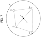
- FIG. 7 is a diagram illustrating an example in which a gravity center of a quadrangle formed on the basis of respective positions of four ports 2 a to 2 d is set as a target position Pt.
- FIG. 8 is a diagram illustrating an example in a case where a gravity center of a triangle formed on the basis of a position of a reserved port 2 c and a position of each of ports 2 a and 2 b that have a usage priority higher than an usage priority of a port 2 c is set as a target position Pt.
- FIG. 9 is a diagram illustrating a schematic configuration example of a management server MS.
- FIG. 10 is a diagram illustrating an example of functional blocks in a control unit 43 .
- FIG. 11 is a diagram illustrating a schematic configuration example of a cargo delivery system Sx.
- FIG. 12 is a flowchart illustrating a flow of processing executed by a cargo delivery system Sx.
- FIG. 13 is a diagram illustrating a display example of a port selection page when a port selection page is received.
- FIG. 14 is a diagram illustrating a display example of a port selection page when a plurality of ports 2 is selected as a cargo receiving place.
- FIG. 15 is a conceptual diagram illustrating time-series changes (an example 1) of a flight path of an UAV 1 a that is flight-controlled.
- FIG. 16 is a conceptual diagram illustrating time-series changes (an example 2) of a flight path of an UAV 1 a that is flight-controlled.
- FIG. 17 is a conceptual diagram illustrating time-series changes (an example 3) of a flight path of an UAV 1 a that is flight-controlled.
- FIG. 1 is a diagram illustrating a schematic configuration example of the unmanned aerial vehicle system S.
- the unmanned aerial vehicle system S includes a plurality of unmanned aerial vehicles (hereinafter, referred to as “UAV (Unmanned Aerial Vehicle)”) 1 a , 1 b , 1 c , . . . , a plurality of take-off and landing facilities for UAV (referred to as “port”) 2 a , 2 b , 2 c , . . .
- UAV Unmanned Aerial Vehicle
- UAV Traffic Management System UAV Traffic Management System
- PMS Port Management System
- the plurality of UAVs 1 a , 1 b , . . . are collectively referred to as UAV 1
- a plurality of ports 2 a , 2 b , . . . are collectively referred to as port 2
- the UAV 1 , the UTMS 3 , and the PMS 4 can communicate with each other via a communication network NW.
- the communication network NW includes, for example, the Internet, a mobile communication network, a radio base station thereof, and the like.
- the UTMS 3 and the PMS 4 execute various processes in cooperation with each other via the communication network NW.
- the UTMS 3 and the PMS 4 may be configured as one management system.
- the UAV 1 can fly in the atmosphere by remote control or fly autonomously.
- the UAV 1 is also called a drone or a multi-copter.
- the UAV 1 is used, for example, for cargo delivery, ground condition observation, or the like.
- the cargo is delivered from the UAV 1 to a recipient at the port 2 where the UAV 1 lands.
- a storage box (delivery box) for temporarily storing cargo is installed at the port 2
- the cargo is transferred from the UAV 1 to the storage box.
- an unmanned ground vehicle hereinafter referred to as “UGV (Unmanned Ground Vehicle)
- UGV Unmanned Ground Vehicle
- the UAV 1 is managed by a GCS (Ground Control Station) and can be remotely operated by an operator from the ground.
- GCS Global Control Station
- the GCS is installed in a control terminal that can be connected to the communication network NW as an application.
- the operator is, for example, a person who operates the control terminal or a controller provided in the control terminal.
- the GCS may be systemized by a server or the like. In this case, the operator is, for example, a system manager or a controller provided in the server.
- the UTMS 3 includes, for example, one or more servers including a control server CS, and the like.
- the control server CS is an example of a control device.
- the UTMS 3 manages traffics and flights of the plurality of UAVs 1 .
- the traffic management of the UAV 1 includes management of a traffic plan before flight of the UAV 1 and management and control of a flight status of the UAV 1 in flight.
- the traffic plan before flight of the UAV 1 is a flight plan and the like including a scheduled route from a departure place to a destination (or a destination area) of the UAV 1 .
- the flight plan may include a scheduled passage time at each point on the scheduled route and a scheduled landing time.
- the management and control of the flight status of the UAV 1 is performed on the basis of aircraft information of the UAV 1 .
- the aircraft information of the UAV 1 includes at least position information of the UAV 1 .
- the position information of the UAV 1 indicates the current position (for example, latitude, longitude, and altitude) of the UAV 1 .
- the current position of the UAV 1 is the flight position of the UAV 1 in flight.
- the aircraft information of the UAV 1 may include speed information and the like of the UAV 1 .
- the speed information of the UAV 1 indicates a flight speed of the UAV 1 .
- the UTMS 3 determines whether the flight plan satisfies a predetermined standard, and if the flight plan satisfies the standard, the flight plan is approved. Moreover, the UTMS 3 performs air traffic control such as giving information and instructions to the UAV 1 . Examples of information given from the UTMS 3 to the UAV 1 include information on a safe flight path, information on a flight possible area, and the like. Further, the UTMS 3 may change the flight plan of the UAV 1 depending on a reservation status of each of the plurality of ports 2 managed by the PMS 4 .
- the PMS 4 includes, for example, one or more servers including a management server MS, and the like.
- the management server MS is an example of a management device.
- the PMS 4 manages a plurality of ports 2 .
- the management of the port 2 includes a reservation management of the port 2 .
- the management of the port 2 is performed on the basis of a port ID of the port 2 , position information of the port 2 , reservation information of the port 2 , and the like.
- the port ID is identification information for identifying the port 2 .
- the position information of the port 2 indicates the position (installation position) of the port 2 .
- the position of the port 2 is represented by latitude and longitude, for example.
- the reservation information of the port 2 includes the aircraft ID of the UAV 1 that reserved the port 2 (landing reservation), the reservation date and time, and the like.
- the aircraft ID is identification information for identifying the UAV 1 .
- one PMS 4 may manage one port 2 (that is, one-to-one correspondence), or one PMS 4 may manage a plurality of ports 2 (that is, one-to-N correspondence).
- a plurality of sets (combinations) of PMSs 4 and the port 2 are provided.
- a plurality of PMSs 4 may exist.
- the plurality of PMSs 4 manages one or a plurality of ports.
- the control server CS and the management server MS may be configured integrally.
- FIG. 2 is a conceptual diagram illustrating a state where the UAV 1 a flies from a departure place to a destination in the unmanned aerial vehicle system S.
- a target position Pt to which the UAV 1 a (an example of the first UAV 1 ) is headed is determined on the basis of respective positions of the ports 2 a and 2 b . This determination is performed by, for example, the control server CS.
- the target position Pt illustrated in FIG. 2 is at the midpoint between the respective positions of the port 2 a and the port 2 b .
- the target position Pt is represented by latitude and longitude, for example.
- the UAV 1 a is controlled to fly toward the determined target position Pt.
- This control is performed by, for example, instructing the target position Pt from the control server CS to the UAV 1 a .
- the port 2 b (destination) to be used for landing by the UAV 1 a is determined in the ports 2 a and 2 b on the basis of the reservation status of each of the ports 2 a and 2 b by the other UAV 1 (second UAV 1 ) different from the UAV 1 a (for example, whether the reservation is made for each time zone).
- This determination is performed by, for example, the management server MS. In the example of FIG.
- the port 2 b that is not reserved by another UAV 1 within a predetermined time before and after the reservation date and time by the UAV 1 a (that is, the reservation date and time is not included within the predetermined time) is determined. Then, when the UAV 1 a reaches the area Ar (in other words, enters), the UAV 1 a is controlled to fly toward the port 2 b .
- This control (flight control of the UAV 1 a ) is performed by, for example, instructing the position of the port 2 b from the control server CS to the UAV 1 a .
- the determination of the target position Pt and the control of the UAV 1 a may be performed by a control unit in the management server MS, the GCS, or the UAV 1 .
- the determination of the port 2 may be performed by the control unit in the control server CS, the GCS, or the UAV 1 .
- a usage priority by the UAV 1 a is set for each of the ports 2 a and 2 b .
- the usage priority is information indicating which port should be preferentially used by the UAV 1 a among the plurality of ports 2 , and can also be referred to as a priority order used for landing by the UAV 1 a .
- the usage priority may be expressed in alphabets or numbers, but in the example of FIG. 2 , it is expressed by A and B, with A being a usage priority higher than B.
- the usage priority “A” of the port 2 a by the UAV 1 a is set higher than the usage priority “B” of the port 2 b by the UAV 1 a , but the reservation status of the port 2 a by the other UAV 1 is reserved. Therefore, the port 2 b that is not reserved by the other UAV 1 is determined as the port 2 used for landing by the UAV 1 a . If the reservation statuses of both the ports 2 a and 2 b by the other UAV 1 are released, the port 2 a with a higher usage priority is determined on the basis of the usage priority of each of the ports 2 a and 2 b by the UAV 1 a .
- the port 2 a used for landing by the UAV 1 a is reserved before the UAV 1 a flies.
- the port 2 b used for landing by the UAV 1 a is determined and reserved in the ports 2 a and 2 b before flight of the UAV 1 a on the basis of the reservation status of each of the ports 2 a and 2 b by the other UAV 1 (for example, the UAVs 1 b , 1 c , etc.) different from the UAV 1 a and the usage priority of each of the ports 2 a and 2 b by the UAV 1 a .
- the port 2 a whose reservation status has been changed may be determined and reserved as the port 2 used for landing by the UAV 1 a .
- the port 2 a which is different from the port 2 b , is reserved (changed in reservation) as the port 2 used for landing by the UAV 1 a instead of the port 2 b reserved before flight of the UAV 1 a on the basis of the reservation status of ports 2 a and 2 b by other the UAV 1 different from the UAV 1 a and the usage priority of ports 2 a and 2 b by the UAV 1 a .
- the control is performed such that the UAV 1 a flies toward newly reserved port 2 a .
- the reservation process is performed by the management server MS, for example.
- the description will be given in consideration of a case where a flight plan change of the UAV 1 b different from the UAV 1 a occurs and the reservation of the port 2 a reserved by the UAV 1 b is canceled.
- the port 2 a is not used for landing at the reservation date and time unless a reservation is made by the other UAV 1 by the reservation date and time.
- the UAV 1 a tries to use the port 2 a at the reservation date and time, if the port 2 a is reserved by the UAV 1 b at the time of reservation by the UAV 1 a , the UAV 1 a is not possible to reserve the port 2 a . Then, the UAV 1 a reserves the port 2 b , which is more inconvenient than the port 2 a for the UAV 1 a instead of the port 2 a , and then uses the port 2 b for landing without knowing that the reservation for the port 2 a by the UAV 1 b has been canceled. In such a case, the port 2 a is not used for landing, and the UAV 1 a uses the inconvenient port 2 b for landing. However, according to the method executed by the system S, the port is used efficiently, and the UAV 1 can use more suitable port 2 for landing.
- FIG. 3 is a diagram illustrating a schematic configuration example of the UAV 1 .
- the UAV 1 includes a drive unit 11 , a positioning unit 12 , a radio communication unit 13 , an imaging unit 14 , a control unit 15 , and the like.
- the UAV 1 includes a rotor (propeller) that is a horizontal rotary blade, various sensors, and a battery or the like that supplies power to each part of the UAV 1 .
- Various sensors used for flight control of the UAV 1 include a barometric sensor, a three-axis acceleration sensor, a geomagnetic sensor, and the like. Detection information detected by the various sensors is output to the control unit 15 . The detection information detected by the barometric sensor is used to calculate the flight speed of the UAV 1 .
- the drive unit 11 includes a motor, a rotating shaft, and the like.
- the drive unit 11 rotates a plurality of rotors by a motor, a rotating shaft, and the like that are driven according to a control signal output from the control unit 15 .
- the positioning unit 12 includes a radio receiver, an altitude sensor, and the like.
- the positioning unit 12 receives a radio wave transmitted from a GNSS (Global Navigation Satellite System) satellite by the radio receiver, and detects the current position (latitude and longitude) of the UAV 1 in the horizontal direction on the basis of the radio wave.
- the current position in the horizontal direction of the UAV 1 may be corrected on the basis of an image captured by the imaging unit 14 or a radio wave transmitted from the radio base station.
- the positioning unit 12 may detect the current position (altitude) in the vertical direction of the UAV 1 using the altitude sensor.
- the position information indicating the current position detected by the positioning unit 12 is output to the control unit 15 .
- the position information of the UAV 1 can be applied in this embodiment even if the information is position information (that is, two-dimensional position information) indicating the current position (latitude and longitude) in the horizontal direction of the UAV 1 .
- the radio communication unit 13 controls communication performed via the communication network NW.
- the imaging unit 14 includes a camera and the like. The imaging unit 14 continuously captures the real space within a range (around the UAV 1 ) that falls within the angle of view of the camera. Image information captured by the imaging unit 14 is output to the control unit 15 .
- the control unit 15 includes a central processing unit (CPU) which is a processor, a read only memory (ROM), a random access memory (RAM), a non-volatile memory, and the like.
- the control unit 15 executes various controls of the UAV 1 according to a control program (program code group) stored in, for example, a ROM or a non-volatile memory.
- control program program code group
- Various types of control include take-off control, flight control, and landing control.
- the position information acquired from the positioning unit 12 the image information acquired from the imaging unit 14 , the detection information acquired from various sensors, flight plan information indicating a pre-registered flight plan, and instruction information from the UTMS 3 are used to control the speed of the rotor, the position, posture, and traveling direction of the UAV 1 , and the like.
- the UAV 1 can fly autonomously from the departure place to the destination.
- the autonomous flight of the UAV 1 is not limited to the autonomous flight in which the control unit 15 provided in the UAV 1 performs flight control.
- the autonomous flight of the UAV 1 includes, for example, an autonomous flight by performing autonomous control as the entire unmanned aerial vehicle system S.
- control unit 15 can also perform flight control in accordance with an instruction signal from the control terminal. Then, during the flight of the UAV 1 , the control unit 15 periodically transmits the aircraft information of the UAV 1 together with the aircraft ID of the UAV 1 to the UTMS 3 via a radio communication unit 23 . The aircraft ID and the aircraft information of the UAV 1 may be transmitted from the UAV 1 to the UTMS 3 via the GCS.
- FIG. 4 is a diagram illustrating a schematic configuration example of the control server CS.
- the control server CS includes a communication unit 31 , a storage unit 32 , and a control unit 33 , etc.
- the communication unit 31 serves to control communication performed via the communication network NW.
- the storage unit 32 includes, for example, a hard disk drive, and the like.
- the storage unit 32 stores the aircraft ID of the UAV 1 , the flight plan information indicating the flight plan of the UAV 1 , and the aircraft information of the UAV 1 in association with each other for each of the plurality of UAVs 1 (for example, the UAV 1 subjected to flight control).
- the control unit 33 includes a CPU that is a processor, a ROM, a RAM, and a non-volatile memory, etc.
- FIG. 5 is a diagram illustrating an example of functional blocks in the control unit 33 .
- the control unit 33 functions, as illustrated in FIG. 5 , as an aircraft information acquisition unit 33 a , a port information acquisition unit 33 b , a target position determination unit 33 c , an area setting unit 33 d , a flight control unit 33 e , and a flight status providing unit 33 f .
- the port information acquisition unit 33 b is an example of an acquisition unit of the control device.
- the target position determination unit 33 c is an example of a first determination unit of the control device.
- the flight control unit 33 e is an example of a first control unit and a second control unit of the control device.
- the aircraft information acquisition unit 33 a periodically acquires the aircraft information of the UAV 1 a from the UAV 1 a or the GCS via the communication unit 31 together with the aircraft ID of the UAV 1 to be flight-controlled (hereinafter, the UAV 1 a is taken as an example).
- the port information acquisition unit 33 b acquires the aircraft ID of the UAV 1 a to be flight-controlled, the port IDs of the plurality of ports 2 selected as landing candidates of the UAV 1 a , the usage priority of each of the plurality of ports 2 by the UAV 1 a , and the port information of each of the plurality of port 2 from the management server MS (port information providing unit 43 c ) via the communication unit 31 .
- the port 2 selected as a landing candidate of the UAV 1 a to be flight-controlled corresponds to the port 2 reserved by the UAV 1 a and the port 2 not reserved by the UAV 1 a .
- the port information acquired by the port information acquisition unit 33 b includes, for example, the position information of the port 2 and reservation information of the port 2 .
- the target position determination unit 33 c determines the target position Pt to which the UAV 1 a is headed on the basis of the positions of each of the plurality of ports 2 selected as landing candidates of the UAV 1 a to be flight-controlled. For example, when the respective positions of the two ports 2 are based, as illustrated in FIG. 2 , the target position determination unit 33 c determines the midpoint between the respective positions of the two ports 2 a and 2 b as the target position Pt.
- the target position determination unit 33 c determines a gravity center (geometric center) of an n (n is an integer of 3 or more) polygon (polygonal shape) formed on the basis of the respective positions of the three or more ports 2 as the target position Pt.
- FIG. 6 illustrates an example in which the gravity center of a triangle formed on the basis of respective positions of the three ports 2 a to 2 c is set as the target position Pt.
- FIG. 7 illustrates an example in which the gravity center of a quadrangle formed on the basis of respective positions of the four ports 2 a to 2 d is set as the target position Pt.
- the target position Pt to which the UAV 1 a is headed is determined on the basis of the positions of the plurality of ports 2 selected as landing candidates, even in a case where the port 2 of the plurality of ports 2 is landed by the UAV 1 a , it is possible to determine an appropriate target position Pt in which the flight efficiency of the UAV 1 a does not decrease as much as possible.
- the target position determination unit 33 c may determine the target position Pt to which the UAV 1 a is headed on the basis of the position of the reserved port 2 and the position of the port 2 (that is, the port 2 not reserved by the UAV 1 a ) for which a usage priority higher than the usage priority of the port 2 is set.
- the target position Pt is determined by excluding the port 2 d in which a usage priority lower than the usage priority of the reserved port 2 c is set.
- the port 2 d with a usage priority lower than the usage priority of reserved port 2 c is not used for landing by the UAV 1 a (that is, reservation is not changed to the port 2 d ). Therefore, it is possible to determine an appropriate target position Pt that does not lower the flight efficiency by excluding such port 2 d .
- the target position determination unit 33 c determines a target position Pt′′ to which the UAV 1 a is headed on the basis of the position of the port 2 whose reservation has been changed and the position of the port 2 (that is, the port 2 not reserved by the UAV 1 a ) for which a usage priority higher than the usage priority of the reservation-changed port 2 is set.
- the area setting unit 33 d sets the area Ar with the target position Pt as a reference (for example, the center).
- the area Ar includes the position of each of the plurality of ports 2 which are used for determining the target position Pt as illustrated in FIGS. 2 , 6 , and 7 .
- the area Ar including the position of the port 2 may be the area Ar in which any one point within the range occupied by the ports 2 (for example, a center point if the port 2 is circular, a point on the boundary of the circle, etc.), or may be the area Ar which includes the entire range occupied by the ports 2 . In a case where a polygon is formed by the positions of the plurality of ports 2 as illustrated in FIGS.
- the area setting unit 33 d may determine the area Ar on the basis of the distance between the position of the port 2 farthest away from the target position Pt among the ports 2 (for example, the position of any one point within the range occupied by the ports 2 ) and the target position Pt. According to this configuration, even in a case where any port 2 among the plurality of ports 2 is used for landing by the UAV 1 a , it is possible to set an appropriate area Ar in which the flight efficiency of the UAV 1 a does not decrease as much as possible. For example, a circle having a radius between the position of the port 2 farthest away from the target position Pt and the target position Pt with the target position Pt as the center may be set as the area Ar.
- the area setting unit 33 d may set the area Ar with the target position Pt as a reference (for example, the center), which includes the position of the reserved port 2 and the position of the port 2 (that is, the port 2 not reserved by the UAV 1 a ) for which a usage priority higher than the usage priority of the reserved port 2 is set.
- the port 2 with a usage priority lower than the reserved usage priority of the port 2 is not used for landing by the UAV 1 a . Therefore, it is possible to set an appropriate area Ar that does not lower the flight efficiency by excluding such port 2 .
- the area setting unit 33 d may set the area Ar on the basis of the reserved port 2 and the distance between the position of the port 2 farthest away from the target position Pt among the ports 2 (that is, the port 2 not reserved by the UAV 1 a ) for which a usage priority higher than the usage priority of the reserved port 2 is set and the target position Pt.
- the area Ar is set within a circle centered on the target position Pt and having a radius r between the position of the port 2 c farthest away from the target position Pt and the target position Pt.
- the area setting unit 33 d may reset the area Ar with the target position Pt as a reference (for example, the center), which is the area Ar′′ which includes the position of the reservation-changed port 2 and the position of the port 2 (that is, the port 2 not reserved by the UAV 1 a ) for which a usage priority higher than the usage priority of the reservation-changed port 2 .
- the determination of the target position Pt and the setting of the area Ar may be performed on a two-dimensional plane.
- the latitude and longitude of each port 2 is converted into position coordinates in a predetermined two-dimensional plane, and the target position Pt may be determined and the area Ar may be set in the two-dimensional plane. It is also possible to convert the target position Pt and the area Ar into latitude and longitude. Incidentally, it is also possible to determine the target position Pt and set the area Ar according to the axiom of non-Euclidean geometry.
- the surface of the earth is regarded as a spherical model
- the midpoint between the plurality of ports 2 on the surface of the earth, or the gravity center of an n-polygon formed on the basis of the position of the plurality of ports 2 is obtained according to the axiom of spherical geometry, and may be set as the target position Pt.
- the area Ar with the target position Pt as a reference may be set on the surface of the earth according to the axiom of spherical geometry.
- the flight control unit 33 e recognizes the flight position of the UAV 1 a to be flight-controlled, the target position Pt, and the boundary position of the area Ar.
- the boundary position is represented by latitude and longitude, for example. Then, the flight control unit 33 e transmits instruction information indicating the target position Pt to the UAV 1 a before the UAV 1 a enters the area Ar, thereby controlling the UAV 1 a to fly toward the target position Pt.
- the reservation information of each of the plurality of ports 2 selected as landing candidates of the UAV 1 a together with the aircraft ID of the UAV 1 a (that is, including the changed reservation information) is acquired by the port information acquisition unit 33 b .
- the flight control unit 33 e determines that the UAV 1 a reaches the area Ar on the basis of the flight position (current position) of the UAV 1 a and the boundary position of the area Ar, the instruction information indicating the position of the port 2 reserved by the UAV 1 a is transmitted to the UAV 1 a to control the UAV 1 a to fly toward the reserved port 2 .
- the UAV 1 a flying toward the target position Pt changes in course at the boundary position of the area Ar and flies toward the position of the reserved port 2 .
- the determination on the course change is made on the basis of the flight position of the UAV 1 a and the boundary position of the area Ar.
- it may be made on the basis of the estimated arrival time at which the UAV 1 a arrives at target position Pt.
- the flight control unit 33 e calculates a required estimation time from the distance between the flight position of the UAV 1 a and the target position Pt and the flight speed of the UAV 1 a , and calculates an estimated arrival time from the calculated required estimation time and the current time.
- the flight control unit 33 e determines that it is a predetermined time before the calculated estimated arrival time (for example, 5 minutes before)
- the instruction information indicating the position of the reserved port 2 by the UAV 1 a is transmitted to the UAV 1 a such that the UAV 1 a flies toward the reserved port 2 .
- the flight status providing unit 33 f transmits flight status information of the UAV 1 a to the management server MS via the communication unit 31 together with the aircraft ID of the UAV 1 a to be flight-controlled.
- the flight status information is information indicating the flight status of the UAV 1 a to be flight-controlled. For example, in a case where the flight control of the UAV 1 a is started, the flight status providing unit 33 f transmits the flight status information indicating that the flight control of the UAV 1 a is started to the management server MS via the communication unit 31 together with the aircraft ID of the UAV 1 a .
- the flight status providing unit 33 f transmits the flight status information indicating that the UAV 1 a has reached the area Ar to the management server MS via the communication unit 31 together with the aircraft ID of the UAV 1 a .
- the flight status providing unit 33 f may transmit the flight status information indicating that it is the predetermined time before he UAV 1 a reaches the area Ar to the management server MS via the communication unit 31 together with the aircraft ID of the UAV 1 a.
- FIG. 9 is a diagram illustrating a schematic configuration example of the management server MS.
- the management server MS includes a communication unit 41 , a storage unit 42 , a control unit 43 , and the like.
- the communication unit 41 controls communication performed through the communication network NW.
- the storage unit 42 includes, for example, a hard disk drive, and the like.
- the storage unit 42 stores the port ID of the port 2 , the name of the port 2 , the position information of the port 2 , and the reservation information of the port 2 in association with each other for each of the plurality of ports 2 .
- the name of the port 2 may include, for example, a facility name such as a station name, a park name, or a store name.
- the reservation information of the port 2 includes the aircraft ID of the UAV 1 that has reserved the port 2 , the reservation date and time, and the like.
- the storage unit 42 stores the aircraft ID of the UAV 1 , the port IDs of the plurality of ports 2 selected as landing candidates of the UAV 1 , and the usage priority of each of the plurality of ports 2 by the UAV 1 in association with each other for each of the plurality of UAVs 1 .
- the control unit 43 includes a CPU which is a processor, a ROM, a RAM, a non-volatile memory, and the like.
- FIG. 10 is a diagram illustrating an example of functional blocks in the control unit 43 .
- the control unit 43 functions as a reservation request receiving unit 43 a , a reservation processing unit 43 b , and the port information providing unit 43 c , for example, according to a program stored in a ROM or a non-volatile memory.
- the reservation processing unit 43 b is an example of an acquisition unit, a first reservation unit, and a second reservation unit of the management device.
- the reservation request receiving unit 43 a receives a reservation request of the port 2 from, for example, a predetermined server on the communication network NW.
- This reservation request includes the aircraft ID of the UAV 1 related to the reservation request (hereinafter, the UAV 1 a is taken as an example), the port IDs of the plurality of ports 2 selected as landing candidates of the UAV 1 a , the usage priority of each of the plurality of ports 2 by the UAV 1 a , and the reservation date and time.
- the plurality of ports 2 that are landing candidates of the UAV 1 a are selected according to an instruction from the operator of the UAV 1 a , for example.
- the plurality of ports 2 that are landing candidates of the UAV 1 a may be automatically selected (without an instruction input by the operator) on the basis of the flight plan of the UAV 1 a .
- the plurality of ports 2 existing in a target area included in the flight plan of the UAV 1 a are selected as the plurality of ports 2 that are landing candidates of the UAV 1 a .
- the plurality of ports 2 that are landing candidates of the UAV 1 a may be selected, for example, in accordance with an instruction from a cargo delivery requester or a cargo recipient of the cargo delivered to the port 2 by the UAV 1 a.
- the usage priority of each of the plurality of ports 2 by the UAV 1 a is set according to an instruction from the operator of the UAV 1 a , for example. According to this configuration, it is possible to set the usage priority according to intention of the operator of the UAV 1 a , and it is possible to improve the convenience for the operator to use the port 2 . Alternatively, the usage priority of each of the plurality of ports 2 may be automatically set on the basis of the flight plan of the UAV 1 a . According to this configuration, it is possible to set the usage priority according to the flight plan of the UAV 1 a , and it is possible to improve the convenience for the UAV 1 a operator to use the port 2 .
- the usage priority may be set so as to increase in an order from the departure place among the plurality of ports 2 selected in the target area.
- the usage priority may be set so as to increase in an order of the short required estimation time from the departure place among the plurality of ports 2 selected in the target area.
- the usage priority of each of the plurality of ports 2 may be set in accordance to an instruction from a delivery requester or a recipient of the cargo delivered to the port 2 by the UAV 1 a . According to this configuration, it is possible to set the usage priority according to intention of the cargo delivery requester or the cargo recipient, and the convenience of using the port 2 by the cargo delivery requester or the cargo recipient can be improved.
- the reservation processing unit 43 b performs a reservation process for determining and reserving the port 2 that the UAV 1 a is used for landing at the reservation date and time included in the reservation request.
- the reservation processing unit 43 b determines the port 2 that is not reserved by the other UAV 1 within a predetermined time before and after the reservation date and time included in the reservation request as the port 2 used for landing by the UAV 1 a related to the reservation request.
- the reservation processing unit 43 b determines the one port 2 that is not reserved as the port 2 that the UAV 1 a is used for landing.
- the reservation processing unit 43 b acquires the usage priority of each of the plurality of ports 2 by the UAV 1 a from the reservation request, for example. Then, the reservation processing unit 43 b determines the port 2 used by the UAV 1 a for landing on the basis of the usage priority of each of the plurality of ports 2 by the UAV 1 a in addition to the reservation status of each of the plurality of ports 2 by the other UAV 1 .
- the port 2 a with the highest usage priority by the UAV 1 a related to the reservation request is determined as the port 2 used for landing by the UAV 1 a .
- the reservation processing unit 43 b stores the reservation information including the aircraft ID of the UAV 1 a that has reserved the port 2 and the reservation date and time in association with the port ID of the determined port 2 so as to reserve (newly reserve) port 2 that the UAV 1 a is used for landing.
- the reservation processing unit 43 b performs a port cancellation check while the UAV 1 a is flying after the reservation of the port 2 used for landing by the UAV 1 a .
- the port cancellation check is a method for detecting a change in the reservation status of the port 2 by the other UAV 1 .
- the port cancellation check it is checked whether the reservation of the port 2 with a usage priority higher than the usage priority of the port 2 reserved by flight-controlled UAV 1 a (that is, the reservation by other UAV 1 ) has been canceled.
- the reservation time of the port 2 with a usage priority higher than the usage priority of the port 2 reserved by flight-controlled UAV 1 a (that is, the reservation time by other UAV 1 ) is changed (for example, whether it has been shortened, extended, or moved to a different time zone) may be checked.
- the port 2 for which the reservation by other UAV 1 is canceled (or, the reservation time has been changed) is determined and reserved as the port 2 used for landing by the UAV 1 a (reservation change) instead of the port 2 already reserved by the UAV 1 a (that is, the port 2 is canceled).
- the port 2 for which the reservation by other UAV 1 is canceled (or, the reservation time has been changed) is determined and reserved as the port 2 used for landing by the UAV 1 a (reservation change) instead of the port 2 already reserved by the UAV 1 a (that is, the port 2 is canceled).
- the reservation processing unit 43 b determines and reserves a port 2 different from the port 2 already reserved by the UAV 1 a as a port 2 to be used for landing by the UAV 1 a on the basis of the reservation status of each of the plurality of ports 2 by the other UAV 1 different from the UAV 1 a and the usage priority of each of the plurality of ports 2 by the UAV 1 a .
- the reservation information associated with the port ID of the determined port 2 is changed (change of the aircraft ID and, in some cases, the reservation date and time).
- the reservation information associated with the port ID of the port 2 already reserved by the UAV 1 a is changed without reservation.
- the port cancellation check may be performed before the UAV 1 a to be flight-controlled enters the area Ar. According to this configuration, it is possible to reserve the port 2 used for landing by the UAV 1 a with a time margin during the flight of the UAV 1 a .
- the port cancellation check may be performed plural times at a predetermined time interval before the UAV 1 a to be flight-controlled enters the area Ar from the start of flight.
- the port cancellation check may be performed when the UAV 1 a to be flight-controlled reaches the area Ar. According to this configuration, it is possible to reserve the port 2 used for landing by the UAV 1 a at a flight position as close as possible to the target position Pt to which the UAV 1 a is headed. Thus, it is possible to increase a possibility that a more suitable port 2 is reserved.
- the port information providing unit 43 c transmits the aircraft ID of the UAV 1 a related to the reservation request received by the reservation request receiving unit 43 a , the port IDs of the plurality of ports 2 selected as landing candidates of the UAV 1 a , the usage priority of each of the plurality of ports 2 by the UAV 1 a , and the port information of each of the plurality of ports 2 to the control server CS via the communication unit 41 .
- This transmission is performed, for example, when the port 2 used for landing by the UAV 1 a related to the reservation request is reserved (new reservation or reservation change).
- FIG. 11 is a diagram illustrating a schematic configuration example of the cargo delivery system Sx.
- the cargo delivery system Sx illustrated in FIG. 11 is configured to include a delivery processing server DS and the like that performs processing related to cargo delivery in addition to the UAV 1 , the port 2 , the UTMS 3 , and the PMS 4 .
- the delivery processing server DS can communicate with the UTMS 3 , the PMS 4 , the GCS, and the like via the communication network NW.
- the delivery processing server DS can be accessed from a mobile terminal T (for example, a smartphone, a tablet, etc.) used by a cargo delivery requester.
- the delivery processing server DS manages information such as the ID, name, telephone number, email address, and the like of the cargo delivery requester.
- the cargo delivery requester may be a cargo recipient or a person other than the recipient.
- FIG. 12 is a flowchart illustrating a flow of processing executed by the cargo delivery system Sx illustrated in FIG. 11 .
- the process illustrated in FIG. 12 is started, for example, when the delivery processing server DS receives a delivery request from the mobile terminal T.
- the delivery processing server DS acquires information such as the cargo to be delivered and the delivery date and time of the cargo in response to the delivery request from the mobile terminal T (Step S 1 ).
- the delivery date and time of the cargo may be specified by the cargo delivery requester, or may be determined according to the criteria of the delivery processing server DS.
- the delivery processing server DS determines the reservation date and time on the basis of the acquired delivery date and time and determines, for example, the UAV 1 a that can deliver the cargo on the determined reservation date and time (Step S 2 ).
- the deliverable UAV 1 a is determined on the basis of information from, for example, the GCS.
- the delivery processing server DS selects, for example, the ports 2 a to 2 d that are the landing candidates of the determined UAV 1 a , and sets the priority order (an example of usage priority) of each of the selected ports 2 a to 2 d (Step S 3 ).
- the priority order an example of usage priority
- the delivery processing server DS transmits a receiving area designating page for accepting designation of a cargo receiving area to the mobile terminal T.
- the receiving area designating page is displayed on the display D of the mobile terminal T.
- the delivery processing server DS transmits a port selection page for accepting the selection of the port 2 in the receiving area specified by the delivery requester to the mobile terminal T.
- the port selection page is displayed on the display D of the mobile terminal T.
- the delivery processing server DS acquires the port IDs, names, and position information of the plurality of ports 2 existing in the receiving area from, for example, the management server MS.
- FIG. 13 is a diagram illustrating a display example of the port selection page when the port selection page is received.
- a map 101 in the reception area designated by the delivery requester is displayed on the port selection page.
- a port mark P corresponding to each of the plurality of ports 2 existing in the receiving area is displayed at a position on the basis of the position information of the respective ports 2 .
- a list of the plurality of ports 2 existing in the receiving area (for example, a name list) may be displayed.
- a selected port display field 102 is displayed on the port selection page illustrated in FIG. 13 .
- the name of each of the plurality of ports 2 selected as a cargo receiving place and the priority order of each of the plurality of ports 2 can be displayed according to the instruction from the delivery requester.
- FIG. 14 is a diagram illustrating a display example of the port selection page when the plurality of ports 2 is selected as a cargo receiving place.
- the ports 2 a to 2 d each corresponding to the designated port marks P are selected by the delivery processing server DS, and the priority order of each of the ports 2 a to 2 d is set by the delivery processing server DS in the designated order.
- the names and priority order of the ports 2 a to 2 d are displayed in the selected port display field 102 as illustrated in FIG. 14 .
- the plurality of ports 2 a to 2 d selected herein are the plurality of ports 2 selected as landing candidates of the UAV 1 a determined in Step S 2 .
- the name of the port 2 a is an A-station port with a first priority order
- the name of the port 2 b is a B-park port with a second priority order
- the name of the port 2 c is a C-station port with a third priority order
- the name of the port 2 d is a D-store port with a fourth priority order.
- the delivery requester can change the priority order set for the selected ports 2 a to 2 d through designation of a pull-down list button 103 .
- an ON/OFF switching button 104 for the port change function is displayed on the port selection page illustrated in FIG. 14 .
- the port change function is a function to change the reserved port 2 with a low priority order to the port 2 with a high priority order after the start of cargo delivery (that is, while the UAV 1 a delivering the cargo is flying).
- the ON/OFF switching button 104 indicates ON, the port change function is set to ON.
- the delivery processing server DS transmits a reservation request for the port 2 to the management server MS.
- This reservation request includes the aircraft ID of the UAV 1 a determined in Step S 2 , the port IDs of the plurality of ports 2 a to 2 d selected in Step S 3 , the priority order set to the plurality of ports 2 a to 2 d in Step S 3 , and the reservation date and time determined in Step S 2 .
- ON/OFF setting information of the port change function is transmitted from the delivery processing server DS to the management server MS.
- information included in the reservation request and the ON/OFF setting information may be transmitted from the delivery processing server DS to the control server CS.
- the management server MS when the management server MS receives the reservation request from the delivery processing server DS, the management server MS performs a reservation process of determining and reserving the port 2 to be used for landing for the UAV 1 a (that is, the UAV 1 a determined in Step S 2 ) related to the reservation request (Step S 4 ).
- the management server MS determines and reserves one port 2 (hereinafter, referred to as “port 2 x ”) to be used for landing by the UAV 1 a among the plurality of ports 2 a to 2 d on the basis of the reservation status of each of the plurality of ports 2 a to 2 d by the other UAV 1 different from the UAV 1 a , and the priority order of each of the plurality of ports 2 a to 2 d by the UAV 1 a .
- the port 2 x that is not reserved by the other UAV 1 and has the highest priority order by the UAV 1 a is determined and reserved.
- flight control information of the UAV 1 a is transmitted from the management server MS to the control server CS together with the aircraft ID of the UAV 1 a .
- the flight control information is information necessary for executing the flight control of the UAV 1 a .
- the flight control information includes, for example, the port IDs of the plurality of ports 2 a to 2 d selected as landing candidates of the UAV 1 a to be flight-controlled, the priority order of the plurality of each of ports 2 a to 2 d by the UAV 1 a , the port information of each of the plurality of ports 2 a to 2 d , and ON/OFF setting information.
- reservation completion information indicating that the reservation is completed is transmitted from the management server MS to the delivery processing server DS.
- the reservation completion information includes the port ID of the reserved port 2 x .
- the delivery processing server DS acquires the name and the position information of the port 2 x corresponding to the port ID included in the received reservation completion information. Then, the delivery processing server DS transmits a mail (or short mail) describing the cargo delivery information including the name and the position information of the reserved port 2 x to a mail address (or telephone number) of the delivery requester.
- a message (for example, an HTTP message) describing the cargo delivery information may be transmitted to the delivery requester's mobile terminal T (an application such as a browser).
- Step S 5 when the control server CS receives the flight control information from the management server MS, the control server CS determines whether the port change function is set to ON on the basis of the ON/OFF setting information included in the flight control information (Step S 5 ). In a case where the control server CS determines that the port change function is set to ON (Step S 5 : YES), the control server CS proceeds to Step S 6 . On the other hand, in a case where the control server CS determines that the port change function is not set to ON (Step S 5 : NO), the control server CS proceeds to Step S 7 . In Step S 6 , the control server CS determines whether the priority order of the port 2 x reserved by the UAV 1 a to be flight-controlled is first.
- Step S 6 it is determined whether the port 2 x reserved by the UAV 1 a has the highest usage priority among the plurality of ports 2 a to 2 d selected as landing candidates of the UAV 1 a to be flight-controlled.
- Step S 7 the control server CS controls the UAV 1 a to fly toward the reserved port 2 x by transmitting instruction information indicating the position of the port 2 x reserved by the UAV 1 a to the UAV 1 a .
- Step S 6 determines that the priority order of the port 2 x reserved by the UAV 1 a is not first (in other words, the priority order is second or lower) (Step S 6 : NO)
- the process proceeds to Step S 8 .
- Step S 8 among the plurality of ports 2 a to 2 d selected as landing candidates of the UAV 1 a , the control server CS determines the target position Pt to which the UAV 1 a is headed on the basis of the position of the port 2 x reserved by the UAV 1 a and the position of the port 2 with a priority order set higher than the priority order of the port 2 x .
- the control server CS determines the target position Pt on the basis of the position of the port 2 d and the positions of the ports 2 a to 2 c in which the priority order higher than the priority order of the port 2 d is set.
- Step S 9 a quadrangular gravity center formed on the basis of each position of the ports 2 a to 2 d is determined as the target position Pt.
- the control server CS sets the area Ar with the target position Pt as a reference determined in Step S 8 , which includes the position of each of the plurality of ports 2 a to 2 d used for determining the target position Pt (Step S 9 ).
- the area Ar is set in a circle with a radius r between the position of the port 2 d farthest away from the target position Pt and the target position Pt.
- the control server CS controls the UAV 1 a to fly toward the target position Pt by transmitting the instruction information indicating the target position Pt determined in Step S 8 to the UAV 1 a (Step S 10 ).
- the flight control of the UAV 1 a is started, the flight status information indicating that the flight control of the UAV 1 a is started is transmitted from the control server CS to the management server MS together with the aircraft ID of the UAV 1 a .
- the flight status information indicating that the UAV 1 a has reached the area Ar is transmitted from the control server CS to the management server MS together with the aircraft ID of the UAV 1 a.
- the management server MS when the management server MS receives the flight status information indicating that the flight control of the UAV 1 a has been started from the control server CS, the management server MS starts a loop process of the port cancellation check.
- the management server MS ends the loop process (exit the loop of the port cancellation check). In other words, the port cancellation check is repeatedly executed before the UAV 1 a reaches the area Ar (in other words, enters).
- the management server MS performs a port cancellation check (Step S 1 ), and determines whether the reservation of the port 2 with a priority order higher than the priority order of the port 2 x reserved by the UAV 1 a (that is, the reservation by the other UAV 1 ) is canceled (Step S 12 ). In a case where the management server MS determines that the reservation of the port 2 with a priority order higher than the priority order of the port 2 x is set has not been canceled (Step S 12 : NO), the management server MS returns to Step S 11 .
- Step S 12 determines that the reservation of the port 2 with a priority order higher than the priority order of the port 2 x is canceled (that is, the empty of the port 2 with the higher priority order has occurred) (Step S 12 : YES)
- the process proceeds to Step S 13 .
- Step S 13 instead of the port 2 x reserved by the UAV 1 a , the management server MS newly determines and reserves (changes the reservation) the port 2 whose reservation has been canceled as the port 2 x used for landing by the UAV 1 a .
- the reservation information of the port 2 x used for landing by the UAV 1 a is changed.
- the management server MS may determine whether the reservation time of the port 2 set with a priority order higher than the priority order of the port 2 x reserved by the UAV 1 a (that is, the reservation time by the other UAV 1 ) has been changed. In this case, the management server MS changes the reservation time of the port 2 with a priority order higher than the priority order of the port 2 x .
- the port 2 whose reservation time has been changed is newly determined and reserved (reservation change) as the port 2 x to be used for landing by the UAV 1 a , instead of the port 2 x reserved by UAV 1 a.
- the flight control information of the UAV 1 a is transmitted from the management server MS to the control server CS together with the aircraft ID of the UAV 1 a .
- reservation change information indicating that the reservation has been changed is transmitted from the management server MS to the delivery processing server DS.
- the reservation change information includes the port ID of the port 2 x whose reservation has been changed.
- the delivery processing server DS transmits a mail (or short mail) describing the port change information including the name and the position information of the port 2 x whose reservation has been changed to the mail address (or telephone number) of the delivery requester.
- a mail or short mail
- the delivery requester's mobile terminal T information indicating that the receiving port of the cargo requested to be delivered is changed is displayed together with the name and the position information of the port 2 x whose reservation has been changed.
- a message describing the port change information for example, an HTTP message
- an HTTP message may be transmitted to the delivery requester's mobile terminal T (an application such as a browser).
- Step S 13 After the reservation change of the port 2 is performed in Step S 13 , when the control server CS receives the flight control information of the UAV 1 a from the management server MS; the control server CS executes the process of Step S 6 again. Namely, it is determined whether the use order of the reserved port 2 x is first among the plurality of ports 2 a to 2 d selected as landing candidates of the UAV 1 a . Then, when the control server CS determines that the priority order of the port 2 x whose reservation has been changed is first, the control server CS transmits the instruction information indicating the position of the port 2 x whose reservation has been changed to the UAV 1 a to control the UAV 1 a to fly toward the port 2 x (Step S 7 ).
- control server CS determines that the priority order of the port 2 x whose reservation has been changed is not first, determines the target position Pt′′ to which the UAV 1 a is headed again on the basis of the position of the port 2 x whose reservation has been changed among the plurality of ports 2 a to 2 d selected as landing candidates of the UAV 1 a and the position of the port 2 with a priority order higher than the priority order of the port 2 x (Step S 8 ).
- the control server CS determines the target position Pt′′ again on the basis of the position of the port 2 c and the positions of the ports 2 a and 2 b with a priority order higher than the priority order of the port 2 c .
- the control server CS sets the area Ar′′ with the target position Pt′′ as a reference determined again in Step S 8 , which includes the position of each of the plurality of ports 2 a to 2 c used for redetermining the target position Pt′′ (Step S 9 ).
- the control server CS transmits instruction information indicating the redetermined target position Pt′′ to the UAV 1 a , thereby controlling the UAV 1 a to fly toward the target position Pt′′ (Step S 10 ).
- the control server CS determines that the UAV 1 a has reached the area Ar or the area Ar′′
- the control server CS transmits the instruction information indicating the position of the finally determined port 2 x to the UAV 1 a to control the UAV 1 a to fly toward the port 2 x (Step S 7 ).
- the flying UAV 1 a arrives at the port 2 x and lands
- landing information indicating that the UAV 1 a has landed at the port 2 x is transmitted from the control server CS to the management server MS together with the aircraft ID of the UAV 1 a .
- the landing information is transmitted from the management server MS to the delivery processing server DS.
- the landing information includes the port ID of the port 2 x where the UAV 1 a has landed.
- the delivery processing server DS acquires the name and the position information of the port 2 x corresponding to the port ID included in the received landing information. Then, the delivery processing server DS transmits a mail (or short mail) describing the delivery completion information including the name and the position information of the port 2 x where the UAV 1 a has landed to the delivery requester's mail address (or telephone number).
- a mail or short mail
- information indicating that the delivery of the requested cargo has been completed is displayed along with the name and the position information of the port 2 x where the UAV 1 a has landed.
- a message for example, an HTTP message
- describing the delivery completion information may be transmitted to the delivery requester's mobile terminal T (an application such as a browser).
- FIGS. 15 to 17 are conceptual diagrams illustrating time-series changes (examples 1 to 3) of the flight path of the UAV 1 a that is flight-controlled during the processing of Steps S 6 to S 13 .
- the numbers in the circles representing the ports 2 a to 2 d indicate the priority order.
- FIG. 15 illustrates an example in a case where the reservation of the port 2 d originally reserved by the UAV 1 a is not changed. In this case, the UAV 1 a is flying toward the target position Pt at time points t 1 and t 2 illustrated in FIG. 15 . Thereafter, when the UAV 1 a reaches the area Ar at time point t 3 illustrated in FIG.
- the UAV 1 a changes the course and flies toward the port 2 d .
- the UAV 1 a will be assigned to fly toward the originally reserved port 2 d from the start of flight.
- FIG. 16 illustrates an example in which the reservation of the port 2 d initially reserved by the UAV 1 a is changed to the port 2 c .
- the UAV 1 a is flying toward the target position Pt at time point t 1 illustrated in FIG. 16 .
- the target position Pt′′ is redetermined by changing the reservation of the port 2 d to the port 2 c at time point t 2 illustrated in FIG. 16 , and the area Ar′′ is reset
- the UAV 1 a changes the course and flies toward the target position Pt′′.
- the UAV 1 a reaches the area Ar′′ at time point t 3 illustrated in FIG. 16
- the UAV 1 a changes the course and flies toward the port 2 c.
- FIG. 17 illustrates an example in a case where the reservation of the port 2 d initially reserved by the UAV 1 a has been changed to the port 2 c , and the reservation of the port 2 c has been changed to the port 2 a (that is, two reservation changes have been made during the flight of the UAV 1 a ).
- the UAV 1 a is flying toward the target position Pt at time point t 1 illustrated in FIG. 17 .
- the target position Pt′′ is redetermined by changing the reservation of the port 2 d to the port 2 c at time point t 2 illustrated in FIG. 17 and the area Ar′′ is reset, the UAV 1 a changes the course and flies toward the target position Pt′′.
- the target position Pt′′ is not redetermined because the priority of the port 2 a is first, and the UAV 1 a changes the course and flies toward the port 2 a . That is, in this case, the UAV 1 a changes the course before reaching the area Ar′′.
- the target position Pt to which the UAV 1 a is headed among the plurality of UAVs 1 is determined on the basis of the position of each of the plurality of ports 2 , and the UAV 1 a is controlled to fly toward the target position Pt.
- the port 2 x to be used for landing of the UAV 1 a is determined on the basis of the reservation status of each of the plurality of ports 2 by the other UAV 1 different from the UAV 1 a among the plurality of the UAVs 1 while the UAV 1 a is flying toward the target position Pt, and the UAV 1 a is controlled to fly toward the determined port 2 x .
- the UAV 1 a can be flight-controlled by determining the port 2 x used for landing so that the flight efficiency is not lowered as much as possible for the UAV 1 a . Therefore, each UAV 1 can use a more suitable port 2 x according to the reservation status of each of the plurality of ports 2 , and the plurality of ports 2 can be used effectively.
- the port 2 b to be used for landing by the UAV 1 a is reserved on the basis of the reservation status of each of the plurality of ports 2 by the other UAV 1 different from the UAV 1 a among the plurality of UAVs 1 , and the usage priority of each of the plurality of ports 2 by the UAV 1 a .
- UAV 1 a is flying
- another port 2 a to be used for landing by the UAV 1 a is reserved instead of the already reserved port 2 b on the basis of the reservation status of each of the plurality of ports 2 by the other UAV 1 different from the UAV 1 a and the above usage priority.
- the plurality of servers included in the cargo delivery system Sx are configured to execute the process illustrated in FIG. 12 , but the process illustrated in FIG. 12 may be executed by one server computer.
- the above-described embodiment has been described about an example in which the technology of the unmanned aerial vehicle system S is applied to the cargo delivery system Sx, but the invention is not limited thereto. If there are the plurality of UAVs 1 and the plurality of ports 2 , and each UAV 1 sets the usage priorities for the plurality of ports 2 and uses the ports for landing, this technology can be applied to various cases.
- the present technology can be applied to a case where the UAV 1 a uses the port 2 to charge or replace the battery, or a case where the UAV 1 a needs to make an emergency landing, or the like.
- the usage priorities for the plurality of ports 2 may be set in accordance with instructions from the operator of the UAV 1 a .
- the usage priority for the port 2 may be automatically set on the basis of the flight plan of the UAV 1 a .
- the unmanned aerial vehicle system S can automatically set the usage priority for each port 2 on the basis of the flight plan in the cases as described in the following (1) and (2).
- the usage priority of the port 2 is set in an order from the current position of the UAV 1 a . According to this configuration, the port 2 that is closer to the current position of the UAV 1 a is set to have a higher usage priority, so that the UAV 1 a can be urgently landed quickly.
- the usage priority of the port 2 is set in an order from the current position of the operator of the UAV 1 a . According to this configuration, the port 2 that is closer to the current position of the operator of the UAV 1 a is set to have a higher usage priority, so that the operator can quickly collect the UAV 1 a.
- the usage priority of the port 2 is set in an order closer to the destination. According to this configuration, the port 2 that is closer to the destination of the UAV 1 a is set to have a higher usage priority, so the time for the UAV 1 a to arrive at the destination can be shortened according to the reservation status of the plurality of ports 2 .
- the usage priority of the port 2 is set in an ascending order from the straight line directly connecting the departure place and destination of the UAV 1 a . According to this configuration, the port 2 that is closer to the straight line has a higher usage priority, so the time for the UAV 1 a to arrive at the destination can be shortened according to the reservation status of the plurality of ports 2 .
- the usage priorities of the ports 2 are set in an ascending order of required estimation time when flying from the departure place of the UAV 1 a to the destination via the port 2 .
- the port 2 with a shorter required estimation time is set to have a higher usage priority, so that it is possible to reduce the time for the UAV 1 a to arrive at the destination according to the reservation status of the plurality of ports 2 .
Abstract
Description
- Patent Literature 1: WO 2018/155700
-
- 1 UAV
- 2 Port
- 3 UTMS
- 4 PMS
- 11 Drive unit
- 12 Positioning unit
- 13 Radio communication unit
- 14 Imaging unit
- 15 Control unit
- 31 Communication unit
- 32 Storage unit
- 33 Control unit
- 33 a Aircraft information acquisition unit
- 33 b Port information acquisition unit
- 33 c Target position determination unit
- 33 d Area setting unit
- 33 e Flight control unit
- 33 f Flight status providing unit
- 41 Communication unit
- 42 Storage unit
- 43 Control unit
- 43 a Reservation request receiving unit
- 43 b Reservation processing unit
- 43 c Port information providing unit
- CS Control server
- MS Management server
- DS Delivery processing server
- T Mobile terminal
- S Unmanned aerial vehicle system
Claims (31)
Applications Claiming Priority (1)
| Application Number | Priority Date | Filing Date | Title |
|---|---|---|---|
| PCT/JP2018/046173 WO2020121530A1 (en) | 2018-12-14 | 2018-12-14 | Control method for unmanned aerial vehicle, management method, control device, management device, and unmanned aerial vehicle system |
Publications (2)
| Publication Number | Publication Date |
|---|---|
| US20210217316A1 US20210217316A1 (en) | 2021-07-15 |
| US11869370B2 true US11869370B2 (en) | 2024-01-09 |
Family
ID=71076397
Family Applications (1)
| Application Number | Title | Priority Date | Filing Date |
|---|---|---|---|
| US16/756,165 Active 2039-11-13 US11869370B2 (en) | 2018-12-14 | 2018-12-14 | Control method for unmanned aerial vehicle, management method, control device, management device, and unmanned aerial vehicle system |
Country Status (4)
| Country | Link |
|---|---|
| US (1) | US11869370B2 (en) |
| EP (1) | EP3693945A4 (en) |
| JP (1) | JP6734998B1 (en) |
| WO (1) | WO2020121530A1 (en) |
Families Citing this family (5)
| Publication number | Priority date | Publication date | Assignee | Title |
|---|---|---|---|---|
| JP7409275B2 (en) | 2020-09-30 | 2024-01-09 | トヨタ自動車株式会社 | Information processing device, method, and program |
| CN112114587B (en) * | 2020-11-23 | 2021-02-05 | 炬星科技(深圳)有限公司 | Distributed congestion control method and robot |
| JP7066885B1 (en) | 2021-01-29 | 2022-05-13 | Kddi株式会社 | Information processing equipment and information processing method |
| CN112578816B (en) * | 2021-02-25 | 2021-05-14 | 四川腾盾科技有限公司 | Estimated arrival time calculation method for large-span-wing large unmanned aerial vehicle |
| WO2023021948A1 (en) * | 2021-08-16 | 2023-02-23 | 株式会社Nttドコモ | Control device and program |
Citations (18)
| Publication number | Priority date | Publication date | Assignee | Title |
|---|---|---|---|---|
| US20120215434A1 (en) * | 2011-02-22 | 2012-08-23 | General Electric Company | Methods and systems for managing air traffic |
| US20140032034A1 (en) * | 2012-05-09 | 2014-01-30 | Singularity University | Transportation using network of unmanned aerial vehicles |
| US20140088288A1 (en) | 2011-03-25 | 2014-03-27 | Kaneka Corporation | Biodegradable polyester fiber having excellent thermal stability and strength, and method for producing same |
| US20140288730A1 (en) * | 2013-03-19 | 2014-09-25 | The Boeing Company | Method of Flying an Unmanned Aerial Vehicle |
| US20160039542A1 (en) * | 2014-08-08 | 2016-02-11 | SZ DJI Technology Co., Ltd | Multi-zone battery exchange system |
| US20160068264A1 (en) * | 2014-09-08 | 2016-03-10 | Qualcomm Incorporated | Methods, Systems and Devices for Delivery Drone Security |
| US20160328979A1 (en) * | 2014-07-15 | 2016-11-10 | Richard Postrel | System and method for automated traffic management of intelligent unmanned aerial vehicles |
| US20170045894A1 (en) * | 2015-08-12 | 2017-02-16 | Qualcomm Incorporated | Autonomous Landing and Control |
| WO2017100579A1 (en) | 2015-12-09 | 2017-06-15 | Dronesense Llc | Drone flight operations |
| US20170278409A1 (en) * | 2016-03-25 | 2017-09-28 | Unmanned Innovation Inc. (dba Airware) | Unmanned aerial vehicle airspace reservation and allocation system |
| US20170344000A1 (en) * | 2016-05-27 | 2017-11-30 | Qualcomm Incorporated | Unmanned Aerial Vehicle Charging Station Management |
| US20180068567A1 (en) * | 2015-03-31 | 2018-03-08 | SZ DJI Technology Co., Ltd | Systems and methods for geo-fencing device communications |
| WO2018155700A1 (en) | 2017-02-27 | 2018-08-30 | 国立大学法人 東京大学 | Flight management system |
| US20180286256A1 (en) * | 2017-03-28 | 2018-10-04 | Subaru Corporation | Flight controlling apparatus, flight controlling method, and non-transitory storage medium |
| US20180290764A1 (en) * | 2017-04-07 | 2018-10-11 | DroneTerminus LLC | Package acceptance, guidance, and refuel system for drone technology |
| US20190019418A1 (en) * | 2015-08-27 | 2019-01-17 | Dronsystems Limited | Automated system of air traffic control (atc) for at least one unmanned aerial vehicle (uav) |
| US20190043368A1 (en) * | 2016-06-10 | 2019-02-07 | ETAK Systems, LLC | Dynamic flying lane management systems and methods for drone air traffic control |
| US20200250993A1 (en) * | 2017-10-16 | 2020-08-06 | Interdigital Patent Holdings, Inc. | Protocol design for unmanned aerial system (uas) traffic management (utm) |
Family Cites Families (1)
| Publication number | Priority date | Publication date | Assignee | Title |
|---|---|---|---|---|
| US8942914B2 (en) * | 2011-02-22 | 2015-01-27 | General Electric Company | Methods and systems for managing air traffic |
-
2018
- 2018-12-14 JP JP2019563318A patent/JP6734998B1/en active Active
- 2018-12-14 US US16/756,165 patent/US11869370B2/en active Active
- 2018-12-14 WO PCT/JP2018/046173 patent/WO2020121530A1/en unknown
- 2018-12-14 EP EP18935990.4A patent/EP3693945A4/en active Pending
Patent Citations (23)
| Publication number | Priority date | Publication date | Assignee | Title |
|---|---|---|---|---|
| JP2012174266A (en) | 2011-02-22 | 2012-09-10 | General Electric Co <Ge> | Methods and systems for managing air traffic |
| US20120215434A1 (en) * | 2011-02-22 | 2012-08-23 | General Electric Company | Methods and systems for managing air traffic |
| US20140088288A1 (en) | 2011-03-25 | 2014-03-27 | Kaneka Corporation | Biodegradable polyester fiber having excellent thermal stability and strength, and method for producing same |
| US20140032034A1 (en) * | 2012-05-09 | 2014-01-30 | Singularity University | Transportation using network of unmanned aerial vehicles |
| US20140288730A1 (en) * | 2013-03-19 | 2014-09-25 | The Boeing Company | Method of Flying an Unmanned Aerial Vehicle |
| JP2014181034A (en) | 2013-03-19 | 2014-09-29 | Boeing Co | Method of flying unmanned aerial vehicle |
| US20160328979A1 (en) * | 2014-07-15 | 2016-11-10 | Richard Postrel | System and method for automated traffic management of intelligent unmanned aerial vehicles |
| US20160039542A1 (en) * | 2014-08-08 | 2016-02-11 | SZ DJI Technology Co., Ltd | Multi-zone battery exchange system |
| JP2017527479A (en) | 2014-08-08 | 2017-09-21 | エスゼット ディージェイアイ テクノロジー カンパニー リミテッドSz Dji Technology Co.,Ltd | Energy supply station |
| US20160068264A1 (en) * | 2014-09-08 | 2016-03-10 | Qualcomm Incorporated | Methods, Systems and Devices for Delivery Drone Security |
| US20180068567A1 (en) * | 2015-03-31 | 2018-03-08 | SZ DJI Technology Co., Ltd | Systems and methods for geo-fencing device communications |
| US20170045894A1 (en) * | 2015-08-12 | 2017-02-16 | Qualcomm Incorporated | Autonomous Landing and Control |
| US20190019418A1 (en) * | 2015-08-27 | 2019-01-17 | Dronsystems Limited | Automated system of air traffic control (atc) for at least one unmanned aerial vehicle (uav) |
| WO2017100579A1 (en) | 2015-12-09 | 2017-06-15 | Dronesense Llc | Drone flight operations |
| US20180357909A1 (en) * | 2015-12-09 | 2018-12-13 | Dronesense Llc | Drone Flight Operations |
| US20170278409A1 (en) * | 2016-03-25 | 2017-09-28 | Unmanned Innovation Inc. (dba Airware) | Unmanned aerial vehicle airspace reservation and allocation system |
| US20170344000A1 (en) * | 2016-05-27 | 2017-11-30 | Qualcomm Incorporated | Unmanned Aerial Vehicle Charging Station Management |
| US20190043368A1 (en) * | 2016-06-10 | 2019-02-07 | ETAK Systems, LLC | Dynamic flying lane management systems and methods for drone air traffic control |
| WO2018155700A1 (en) | 2017-02-27 | 2018-08-30 | 国立大学法人 東京大学 | Flight management system |
| US20210005091A1 (en) * | 2017-02-27 | 2021-01-07 | The University Of Tokyo | Flight management system |
| US20180286256A1 (en) * | 2017-03-28 | 2018-10-04 | Subaru Corporation | Flight controlling apparatus, flight controlling method, and non-transitory storage medium |
| US20180290764A1 (en) * | 2017-04-07 | 2018-10-11 | DroneTerminus LLC | Package acceptance, guidance, and refuel system for drone technology |
| US20200250993A1 (en) * | 2017-10-16 | 2020-08-06 | Interdigital Patent Holdings, Inc. | Protocol design for unmanned aerial system (uas) traffic management (utm) |
Non-Patent Citations (1)
| Title |
|---|
| International Search Report for PCT/JP2018/046173 dated Mar. 19, 2019 [PCT/ISA/210]. |
Also Published As
| Publication number | Publication date |
|---|---|
| JPWO2020121530A1 (en) | 2021-02-15 |
| EP3693945A4 (en) | 2020-11-11 |
| JP6734998B1 (en) | 2020-08-05 |
| EP3693945A1 (en) | 2020-08-12 |
| WO2020121530A1 (en) | 2020-06-18 |
| US20210217316A1 (en) | 2021-07-15 |
Similar Documents
| Publication | Publication Date | Title |
|---|---|---|
| US11869370B2 (en) | Control method for unmanned aerial vehicle, management method, control device, management device, and unmanned aerial vehicle system | |
| US11113976B2 (en) | Unmanned aerial vehicle management system | |
| EP3422325A1 (en) | Unmanned aerial vehicle, delivery system, control method for unmanned aerial vehicle, and program for controlling unmanned aerial vehicle | |
| US20140166816A1 (en) | Automated hazard handling routine engagement | |
| JP6754920B1 (en) | Landing management device, landing management method, and landing management system | |
| JP7300437B2 (en) | Processing system, unmanned flightable aircraft, and method for estimating dust conditions | |
| US11747807B2 (en) | Control device and control method for controlling aerial vehicle | |
| JP6705066B1 (en) | Unmanned aerial vehicle operation management device, takeoff and landing facility management device, unmanned aerial vehicle operation management method, and unmanned aerial vehicle system | |
| JP2020149640A (en) | Flight system and landing control method | |
| WO2023010451A1 (en) | Unmanned aerial vehicle scheduling method, server, parking apron pad device, system, and storage medium | |
| JP6726814B1 (en) | Processing system, unmanned aerial vehicle, and flight path determination method | |
| WO2021245844A1 (en) | Landing information determination device, landing information determination system, landing information determination method, and computer-readable medium | |
| US11928973B2 (en) | Processing system, aerial vehicle capable of flying unmanned, and dust condition estimation method | |
| JP7327668B2 (en) | POWER SUPPLY INFORMATION DETERMINATION DEVICE, POWER SUPPLY INFORMATION DETERMINATION METHOD, AND PROGRAM | |
| JP7319420B2 (en) | Processing system, unmanned flightable aircraft, and method for estimating dust conditions | |
| JP6916255B2 (en) | Management devices, management methods, and programs in flight systems |
Legal Events
| Date | Code | Title | Description |
|---|---|---|---|
| AS | Assignment |
Owner name: RAKUTEN, INC., JAPAN Free format text: ASSIGNMENT OF ASSIGNORS INTEREST;ASSIGNORS:TAZUME, TOSHIAKI;MIZUKAMI, HAYATO;ZHOU, QINGNAN;REEL/FRAME:052401/0907 Effective date: 20190201 |
|
| FEPP | Fee payment procedure |
Free format text: ENTITY STATUS SET TO UNDISCOUNTED (ORIGINAL EVENT CODE: BIG.); ENTITY STATUS OF PATENT OWNER: LARGE ENTITY |
|
| STPP | Information on status: patent application and granting procedure in general |
Free format text: APPLICATION DISPATCHED FROM PREEXAM, NOT YET DOCKETED |
|
| AS | Assignment |
Owner name: RAKUTEN GROUP INC, JAPAN Free format text: CHANGE OF NAME;ASSIGNOR:RAKUTEN INC;REEL/FRAME:056816/0068 Effective date: 20210525 |
|
| STPP | Information on status: patent application and granting procedure in general |
Free format text: DOCKETED NEW CASE - READY FOR EXAMINATION |
|
| STPP | Information on status: patent application and granting procedure in general |
Free format text: NON FINAL ACTION MAILED |
|
| STPP | Information on status: patent application and granting procedure in general |
Free format text: RESPONSE TO NON-FINAL OFFICE ACTION ENTERED AND FORWARDED TO EXAMINER |
|
| STPP | Information on status: patent application and granting procedure in general |
Free format text: RESPONSE TO NON-FINAL OFFICE ACTION ENTERED AND FORWARDED TO EXAMINER |
|
| STPP | Information on status: patent application and granting procedure in general |
Free format text: FINAL REJECTION MAILED |
|
| STPP | Information on status: patent application and granting procedure in general |
Free format text: NON FINAL ACTION MAILED |
|
| STPP | Information on status: patent application and granting procedure in general |
Free format text: RESPONSE TO NON-FINAL OFFICE ACTION ENTERED AND FORWARDED TO EXAMINER |
|
| STPP | Information on status: patent application and granting procedure in general |
Free format text: NOTICE OF ALLOWANCE MAILED -- APPLICATION RECEIVED IN OFFICE OF PUBLICATIONS |
|
| STPP | Information on status: patent application and granting procedure in general |
Free format text: PUBLICATIONS -- ISSUE FEE PAYMENT RECEIVED |
|
| STPP | Information on status: patent application and granting procedure in general |
Free format text: PUBLICATIONS -- ISSUE FEE PAYMENT VERIFIED |
|
| STCF | Information on status: patent grant |
Free format text: PATENTED CASE |