US11844426B1 - Desk with an upright partition on a work surface that supports laterally-movable attachments - Google Patents
Desk with an upright partition on a work surface that supports laterally-movable attachments Download PDFInfo
- Publication number
- US11844426B1 US11844426B1 US17/532,295 US202117532295A US11844426B1 US 11844426 B1 US11844426 B1 US 11844426B1 US 202117532295 A US202117532295 A US 202117532295A US 11844426 B1 US11844426 B1 US 11844426B1
- Authority
- US
- United States
- Prior art keywords
- desk
- support structure
- work surface
- implementations
- upright partition
- Prior art date
- Legal status (The legal status is an assumption and is not a legal conclusion. Google has not performed a legal analysis and makes no representation as to the accuracy of the status listed.)
- Active, expires
Links
- 238000005192 partition Methods 0.000 title claims abstract description 65
- 230000007246 mechanism Effects 0.000 claims description 56
- 230000008878 coupling Effects 0.000 claims description 10
- 238000010168 coupling process Methods 0.000 claims description 10
- 238000005859 coupling reaction Methods 0.000 claims description 10
- 238000001514 detection method Methods 0.000 claims description 3
- 241000544076 Whipplea modesta Species 0.000 description 7
- 238000005516 engineering process Methods 0.000 description 4
- 238000003860 storage Methods 0.000 description 4
- 230000008859 change Effects 0.000 description 2
- 230000006870 function Effects 0.000 description 2
- 230000000717 retained effect Effects 0.000 description 2
- 239000011800 void material Substances 0.000 description 2
- 239000002699 waste material Substances 0.000 description 2
- 244000236521 Bupleurum rotundifolium Species 0.000 description 1
- 241000196324 Embryophyta Species 0.000 description 1
- 238000005304 joining Methods 0.000 description 1
- 238000004519 manufacturing process Methods 0.000 description 1
- 239000002184 metal Substances 0.000 description 1
- 238000000034 method Methods 0.000 description 1
- 230000004048 modification Effects 0.000 description 1
- 238000012986 modification Methods 0.000 description 1
- 230000004044 response Effects 0.000 description 1
- XLYOFNOQVPJJNP-UHFFFAOYSA-N water Substances O XLYOFNOQVPJJNP-UHFFFAOYSA-N 0.000 description 1
Images


Classifications
-
- A—HUMAN NECESSITIES
- A47—FURNITURE; DOMESTIC ARTICLES OR APPLIANCES; COFFEE MILLS; SPICE MILLS; SUCTION CLEANERS IN GENERAL
- A47B—TABLES; DESKS; OFFICE FURNITURE; CABINETS; DRAWERS; GENERAL DETAILS OF FURNITURE
- A47B21/00—Tables or desks for office equipment, e.g. typewriters, keyboards
- A47B21/02—Tables or desks for office equipment, e.g. typewriters, keyboards with vertical adjustable parts
-
- A—HUMAN NECESSITIES
- A47—FURNITURE; DOMESTIC ARTICLES OR APPLIANCES; COFFEE MILLS; SPICE MILLS; SUCTION CLEANERS IN GENERAL
- A47B—TABLES; DESKS; OFFICE FURNITURE; CABINETS; DRAWERS; GENERAL DETAILS OF FURNITURE
- A47B9/00—Tables with tops of variable height
-
- A—HUMAN NECESSITIES
- A47—FURNITURE; DOMESTIC ARTICLES OR APPLIANCES; COFFEE MILLS; SPICE MILLS; SUCTION CLEANERS IN GENERAL
- A47B—TABLES; DESKS; OFFICE FURNITURE; CABINETS; DRAWERS; GENERAL DETAILS OF FURNITURE
- A47B2200/00—General construction of tables or desks
- A47B2200/0066—Workstations
- A47B2200/0075—Computer kiosks or stands
-
- A—HUMAN NECESSITIES
- A47—FURNITURE; DOMESTIC ARTICLES OR APPLIANCES; COFFEE MILLS; SPICE MILLS; SUCTION CLEANERS IN GENERAL
- A47B—TABLES; DESKS; OFFICE FURNITURE; CABINETS; DRAWERS; GENERAL DETAILS OF FURNITURE
- A47B2200/00—General construction of tables or desks
- A47B2200/12—Vanity or modesty panels
-
- A—HUMAN NECESSITIES
- A47—FURNITURE; DOMESTIC ARTICLES OR APPLIANCES; COFFEE MILLS; SPICE MILLS; SUCTION CLEANERS IN GENERAL
- A47B—TABLES; DESKS; OFFICE FURNITURE; CABINETS; DRAWERS; GENERAL DETAILS OF FURNITURE
- A47B2220/00—General furniture construction, e.g. fittings
- A47B2220/0091—Electronic or electric devices
Definitions
- the present disclosure relates to a desk with an upright partition that supports laterally-movable attachments.
- Desks are known, typically as work surfaces for people at a fixed height. Cubicles are known as work areas, typically for people working at desks. Height-adjustable desks are known.
- the desk may be configured to be positioned for a person (i.e., a user) in a sitting and/or standing position.
- relative positional terms including but not limited to rear side, front side, left side and right side may refer to the point of view of a user positioned at the desk in a common fashion.
- the desk may include one or more of a work surface, a left-side support structure, a right-side support structure, a core body, a working body that provides the work surface, one or more modular attachments, one or more mounting brackets, and/or other components.
- FIG. 1 E shows a disassembled and/or exploded view of a core body, a first lifting mechanism, and a second lifting mechanism, in accordance with one or more implementations.
- FIG. 1 H shows a desk with an upright partition that supports another laterally-movable attachment, in accordance with one or more implementations.
- FIG. 2 C shows a front view 200 C of a working body, in accordance with one or more implementations.
- FIG. 2 D shows a rear view 200 D of a working body, in accordance with one or more implementations.
- FIG. 3 A shows a front view 300 A of a core body, in accordance with one or more implementations.
- FIG. 3 B shows a rear view 300 B of a core body, in accordance with one or more implementations.
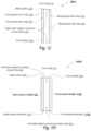
- FIG. 3 C shows a right-side view 300 C of a core body, in accordance with one or more implementations.
- FIG. 3 E shows a bottom view 300 E of a core body, in accordance with one or more implementations.
- FIG. 3 F shows a top view 300 F of a core body, in accordance with one or more implementations.
- FIG. 4 A shows an outside view 400 A of a right-side support structure, in accordance with one or more implementations.
- FIG. 4 B shows an inside view 400 B of a right-side support structure, in accordance with one or more implementations.
- FIG. 4 C shows an outside view 400 C of a left-side support structure, in accordance with one or more implementations.
- FIG. 4 D shows an inside view 400 D of a left-side support structure, in accordance with one or more implementations.
- FIG. 5 A shows a front view 500 A of a modesty panel, in accordance with one or more implementations.
- FIG. 5 B shows a rear view 500 B of a modesty panel, in accordance with one or more implementations.
- FIG. 6 shows an assembled view of a desk, in accordance with one or more implementations.
- FIG. 7 shows a view of a modular attachment configured to be attached to a desk, in accordance with one or more implementations.
- FIG. 8 shows an assembled view of a desk, in accordance with one or more implementations.
- FIG. 9 shows a view of a modular attachment configured to be attached to a desk, in accordance with one or more implementations.
- FIG. 10 A- 10 B show mounting brackets for use with a desk, in accordance with one or more implementations.
- FIGS. 11 A- 11 B- 11 C show an upright partition for use with a desk, the upright partition configured to support laterally-movable attachments, in accordance with one or more implementations.
- FIG. 12 A shows a partially assembled desk with an upright partition that supports laterally-movable attachments, in accordance with one or more implementations.
- FIG. 12 B shows a detailed view of a section or fraction of a desk with an upright partition that supports laterally-movable attachments, in accordance with one or more implementations.
- FIGS. 13 A- 13 B show a laterally-movable attachment for use with a desk with an upright partition that supports laterally-movable attachments, in accordance with one or more implementations.
- FIGS. 14 A- 14 B show a different laterally-movable attachment for use with a desk with an upright partition that supports laterally-movable attachments, in accordance with one or more implementations.
- FIG. 1 A shows a desk 100 with support structures (i.e., a left-side support structure 24 on the left side of desk 100 and a right-side support structure 22 on the right side of desk 100 as viewed by a user and as depicted in FIG. 1 A ) and an upright partition 19 configured to support laterally-movable attachments, in accordance with one or more implementations.
- support structures may be referred to as “legs”.
- the support structures of desk 100 may be configured to support modular attachments.
- the modular attachments can be attached on either the left side or the right side of desk 100 , or on both sides at the same time.
- modular attachments may be attached either outside the support structures, between the support structures, or both.
- FIGS. 1 F- 1 G- 1 H show desk 100 and upright partition 19 , and show, attached to upright partition 19 , different laterally-movable attachments such as attachment 19 c , attachment 19 d , and attachment 19 d , respectively.
- Modular attachment 15 may be configured to provide extended functionality to the user of desk 100 , as described in this disclosure.
- desk 100 may be configured to be positioned for a user in a sitting position and/or standing position.
- FIG. 1 A shows desk 100 in a standing and/or lifted position.
- Desk 100 may include one or more of a working body 2 , a control circuitry 2 a , a work surface 3 , upright partition 19 , a control interface 5 , a core body 10 , left-side support structure 24 , right-side support structure 22 , a first lifting mechanism 31 , a second lifting mechanism 32 , and/or other components.
- Desk 100 may further include one or more modular attachments 15 (e.g., see FIG. 6 and FIG. 8 ), one or more mounting brackets 16 (e.g., see FIG. 6 and FIG.
- FIGS. 1 F- 1 G- 1 H these are depicted as dotted rectangles to indicate these components may be embedded within desk 100 , and/or otherwise not readily visible from a particular viewing angle), one or more laterally-movable attachments (e.g., see FIGS. 1 F- 1 G- 1 H , as well as FIGS. 13 A- 13 B and 14 A- 14 B ), and/or other components.
- Left-side support structure 24 and right-side support structure 22 may be configured to be coupled to core body 10 to provide the entire desk stability while being raised, lowered, and/or in use.
- First lifting mechanism 31 and second lifting mechanism 32 may be coupled to core body 10 and working body 2 .
- other components may be configured and/or customized for the desk as preferred by the users.
- FIG. 1 B shows a perspective elevated view 100 B of a height-adjustable desk in a sitting and/or lowered position.
- first lifting mechanism 31 and second lifting mechanism 32 may be (at least partially) housed within core body 10 .
- first lifting mechanism 31 and second lifting mechanism 32 may be mostly hidden from view.
- Working body 2 may be configured to include a work surface 3 coupled to a work surface support structure 4 as shown in FIG. 1 C , as well as an upright partition 19 coupled to work surface 3 as depicted.
- Working body 2 may be configured to adjustably couple to first lifting mechanism 31 ( FIG. 1 A ) and second lifting mechanism 32 ( FIG. 1 A ).
- Working body 2 may be configured to be supported by core body 10 at a rear side of desk 100 by virtue of core body 10 being coupled to first lifting mechanism 31 ( FIG. 1 A ), second lifting mechanism 32 ( FIG. 1 A ), right-side support structure 22 ( FIG. 1 A ), and left-side support structure 24 ( FIG. 1 A ).
- Work surface 3 of desk 100 may be disposed at a current height.
- the current height may be adjustable.
- the adjustments in the current height of work surface 3 may have a vertical range of about 20 inches.
- the adjustments in the current height of work surface 3 may have a vertical range between about 15 inches and 25 inches.
- the adjustments in the current height of work surface 3 may have a vertical range between about 18 inches and 24 inches.
- work surface 3 of working body 2 may have a surface area ranging from 46 inches to 52 inches in width.
- work surface 3 of working body 2 may have a surface area of about 26 inches deep.
- work surface 3 of working body 2 may have a surface area ranging between about 22 and about 30 inches deep.
- control interface 5 may be configured to receive user input from the user.
- the location of control interface 5 on the desk is not limited by its exemplary illustration in FIG. 1 C , which is merely meant to represent a convenient position for users to engage with control interface 5 to adjust the current height of work surface 3 .
- control interface 5 may have one or more buttons to adjust the current height of work surface 3 .
- control interface 5 as shown in front view 200 C ( FIG.
- working body 2 may have one or more of a lift button, a lower button, a lock/un-lock button, a memory button designating a user's preferred current height, and/or one or more other buttons used to control, adjust, and/or otherwise operate the current height of work surface 3 .
- the one or more cavities of work surface support structure 4 of working body 2 may be referred to as openings, orifices, chambers, cutouts, mortices, voids, vacant volumes, and/or other terminology to indicate useable spaces within work surface support structure 4 .
- front facing center cavity 8 a may contain a center tray 9 .
- center tray 9 may be inserted and/or withdrawn from front facing center cavity 8 a .
- front facing adjacent cavity 8 b may contain a side tray 7 .
- side tray 7 may be inserted and/or withdrawn from front facing adjacent cavity 8 b .
- the cavities of work surface support structure 4 may contain other desk attachments and/or components other than trays.
- the cavities may include storage areas, keyboard and mouse housing, open-faced cavities, and/or other cavity functions.
- FIG. 1 F shows desk 100 with upright partition 19 that supports laterally-movable attachment 19 c .
- laterally-movable attachment 19 c is a small shelf.
- Upright partition 19 may include lateral groove 21 (which may also be referred to as a track). Lateral groove 21 may extend laterally from the left side to the right side of upright partition 19 as depicted, e.g., near the top of upright partition 19 .
- Laterally-movable attachment 19 c may include one or more fasteners 21 a (e.g., as depicted, two fasteners such as screws or bolts that fit into tapped holes that have been made into laterally-movable attachment 19 c , as shown in more detail in FIG.
- Fasteners 21 a may be configured to removably attach to lateral groove 21 , such that a user can move laterally-movable attachment 19 c laterally along lateral groove 21 , as preferred.
- FIG. 1 G shows desk 100 with upright partition 19 that supports laterally-movable attachment 19 d .
- laterally-movable attachment 19 d is a wider shelf.
- laterally-movable attachment 19 d may be as wide as upright partition 19 .
- Laterally-movable attachment 19 d may include multiple fasteners (e.g., as depicted, a first set of fasteners 21 a and a second set of fasteners 21 b ) configured to mechanically couple laterally-movable attachment 19 d , via lateral groove 21 , to upright partition 19 .
- Fasteners 21 a and 21 b may be configured to removably attach to lateral groove 21 , such that a user can couple or detach laterally-movable attachment 19 c laterally along lateral groove 21 , as preferred.
- FIG. 1 H shows desk 100 with upright partition 19 that supports laterally-movable attachment 19 e .
- laterally-movable attachment 19 e is a diagonal support, such as may be used as a drafting table, a laptop stand, a tablet support, and/or other functionalities.
- laterally-movable attachment 19 e may rest on work surface 3 .
- Laterally-movable attachment 19 e may include fasteners 21 configured to mechanically couple laterally-movable attachment 19 e , via lateral groove 21 , to upright partition 19 .
- Fasteners 21 a may be configured to removably attach to lateral groove 21 , such that a user can move, couple, or detach laterally-movable attachment 19 e laterally along lateral groove 21 , as preferred.
- FIG. 2 A shows a top view 200 A of a working body 2 , including work surface 3 and vertical slot 3 a .
- FIG. 2 B shows a bottom view 200 B of working body 2 .
- working body 2 may include a first motor housing 2 c positioned at the rear of work surface support structure 4 .
- working body 2 may include a second motor housing 2 e , positioned opposite of first motor housing 2 c and at the rear of work surface support structure 4 .
- working body 2 may include a control circuitry 2 a , a first control circuitry cutout 2 f , a second control circuitry cutout 2 d , and/or other components.
- control circuitry 2 a may be configured to detect user input received by control interface 5 . Responsive to the detection of the user input, first lifting mechanism 31 may be controlled to either lift working body 2 and increase the current height of work surface 3 or lower working body 2 and decrease the current height of work surface 3 .
- second lifting mechanisms 32 may be controlled to either lift working body 2 and increase the current height of work surface 3 or lower working body 2 and decrease the current height of work surface 3 , e.g., in synchrony with lifting mechanism 31 .
- first control circuitry cutout 2 f (e.g., orifice, chamber, opening, mortice, void, vacant volume) may be configured to allow users to easily access and connect control circuitry 2 a to first lifting mechanism 31 ( FIG. 1 A ) when first lifting mechanism 31 ( FIG. 1 A ) is adjustably coupled to working body 2 .
- second control circuitry cutout 2 d (e.g., orifice, chamber, opening, mortice, void, vacant volume) may be configured to allow users to easily access and connect control circuitry 2 a to second lifting mechanism 32 ( FIG. 1 A ) when second lifting mechanism 32 ( FIG. 1 A ) is adjustably coupled to working body 2 .
- Second pair of motor screw holes 2 h may be configured to include one or more of screws, nuts, bolts, pins, and/or one or more other fastening hardware or fasteners to secure/fasten second motor 32 c ( FIG. 1 D ) of second lifting mechanism 32 ( FIG. 1 D ) to second motor housing 2 e ( FIG. 2 B ) of working body 2 .
- FIG. 3 A shows a core body front view 300 A.
- FIG. 3 B shows a core body rear view 300 B.
- front panel 12 a (see FIG. 3 A ) and back panel 12 b (see FIG. 3 B ) of core body 10 may include a first lifting column top screw hole 12 c and a second lifting column top screw hole 12 d .
- First lifting column top screw hole 12 c may be configured to secure first lifting column 31 a ( FIG. 1 D ) to core body 10 .
- Second lifting column top screw hole 12 d may be configured to secure second lifting column 32 a ( FIG. 1 D ) to core body 10 .
- FIG. 3 C shows a right-side view 300 C of core body 10 .
- FIG. 3 D shows a left-side view 300 D of core body 10 .
- back panel 12 b may include a back-panel front side 12 x ( FIG. 3 C ), and a back-panel rear side 12 j ( FIG. 3 C ).
- Back-panel front side 12 x ( FIG. 3 C ) of back panel 12 b may be coupled to the rear of column housing frame 11 ( FIG. 1 E ).
- Back panel 12 b may be configured to provide support for core body 10 by being inserted into a left-sided back opening 24 a ( FIG. 4 C ) of left-side support structure 24 ( FIG. 4 C ) and a right-sided back opening 22 a ( FIG. 4 A ) of right-side support structure 22 ( FIG. 4 A ).
- back panel 12 b may include a back-panel height 12 y ( FIG. 3 D ), and a back-panel thickness 12 k ( FIG. 3 D ).
- Second pair of lifting column screw holes 12 q may be configured to include one or more of screws, nuts, bolts, pins, and/or one or more other fastening hardware or fasteners to secure/fasten second lifting column 32 a ( FIG. 1 D ) of second lifting mechanism 32 ( FIG. 1 D ) to second lifting column housing 12 h ( FIG. 1 E ) of core body 10 .
- first lifting mechanism 31 may be coupled to core body 10 by first lifting column 31 a ( FIG. 1 D ) being inserted into first lifting column housing 12 g ( FIG. 1 E ).
- second lifting mechanism 32 may be coupled to core body 10 by second lifting column 32 a ( FIG. 1 D ) being inserted into second lifting column housing 12 h ( FIG. 1 E ).
- both views 300 E and 300 F show a length of front panel 12 a and a length of back panel 12 b , each of which may be greater than a length of column housing frame 11 .
- the extra length of the front panel 12 a may be configured to be inserted into right-sided front opening 22 c ( FIG. 4 A ) and left-sided front opening 24 c ( FIG. 4 C ).
- FIG. 4 A right-sided front opening 22 c
- left-sided front opening 24 c FIG. 4 C
- inserting front panel 12 a into right-sided front opening 22 c and left-sided front opening 24 c leaves almost the entirety of right-sided front opening 22 c and left-sided front opening 24 c available (minus front-panel thickness 112 g ), e.g., for one or more modular attachments (such as, by way of non-limiting example, modular attachment 15 as depicted in FIG. 6 ).
- the extra length of the back panel 12 b may be configured to be inserted into right-sided back opening 22 a ( FIG. 4 A ) and left-sided back opening 24 a ( FIG. 4 C ).
- first lifting mechanism 31 may include one or more of first motor 31 c , a first telescoping arm 31 b , first lifting column 31 a , and/or other components. In some implementations, first lifting mechanism 31 may have at least two stages. Second lifting mechanism 32 may include one or more of second motor 32 c , a second telescoping arm 32 b , second lifting column 32 a , and/or other components. In some implementations, second lifting mechanism 32 may have at least two stages. In some implementations, first and second telescoping arms ( 31 b , 32 b ) are the only visibly moving parts of the entire desk when the desk is being lifted and/or lowered (during use, after assembly).
- first lifting mechanism 31 may include a first mechanical linear actuator.
- Second lifting mechanism 32 may include a second mechanical linear actuator. Controlling first and second lifting mechanisms ( 31 , 32 ) may include controlling the first mechanical linear actuator and the second mechanical linear actuator in synchrony.
- left-side support structure 24 may be disposed at a left side of desk 100 with respect to work surface 3 of working body 2 .
- left-side support structure 24 may be stationary during adjustments of the current height of work surface 3 .
- FIG. 4 D shows an inside view 400 D of left-side support structure 24 .
- FIG. 4 C shows an outside view 400 C of left-side support structure 24 .
- left-side support structure 24 may include left-sided back opening 24 a and left-sided front opening 24 c in front of left-sided back opening 24 a.
- Left-sided back opening 24 a of left-side support structure 24 may be configured to include a first width at least as wide as back-panel thickness 12 k ( FIG. 3 D ) and a first height at least as long as back-panel height 12 y ( FIG. 3 D ).
- left-side support structure 24 may be configured to include a left-sided stile 24 b , disposed between left-sided back opening 24 a and left-sided front opening 24 c .
- Left-sided stile 24 b may be configured to have a width less than a distance between back-panel front side 12 x ( FIG. 3 C ) and front-panel rear side 12 f ( FIG. 3 C ).
- left-sided stile 24 b of left side support structure 24 may be identified as one or more of a left-sided post, a left-sided connector, a left-sided closing, a left-sided panel, a left-sided member, and/or other terms that properly identify 24 b.
- left-side support structure 24 may be configured to include left-sided front opening 24 c comprised of a width and a height.
- the width of left-sided front opening 24 c may be in the range of 80%-95% of a width of left-side support structure 24 .
- the width of left-sided front opening 24 c may be in the range of 70%-85% of a width of left-side support structure 24 .
- the width of left-sided front opening 24 c may be in the range of 60%-80% of a width of left-side support structure 24 , as depicted in FIG. 4 A .
- the height of left-sided front opening 24 c may be in the range of 80%-95% of a height of left-side support structure 24 . In some implementations, the height of left-sided front opening 24 c may be in the range of 70%-85% of a height of left-side support structure 24 . In some implementations, the height of left-sided front opening 24 c may be in the range of 60%-80% of a height of left-side support structure 24 , as depicted in FIG. 4 A . In some implementations, the width of left-sided front opening 24 c may range between 14 and 17 inches, or between 15 and 20 inches. For example, the width of left-sided front opening 24 c may be about 15 inches. In some implementations, the height of left-sided front opening 24 c may range between 18 and 23 inches, or between 20 and 25 inches. For example, the height of left-sided front opening 24 c may be about 21 inches.
- a shape of left-side support structure 24 as viewed from the left side of desk 100 may be a rectangular shape.
- the shape of left-side support structure 24 as viewed from the left side of desk 100 may be one or more of a circle, triangle, and/or other geometric shapes. It is noted that a difference in the shape of the left-side support structure as viewed from the left side may change many other components of desk 100 .
- the same manner of coupling components together would be retained so that working body 2 would be lifted and/or lowered by lifting mechanisms positioned at its rear and having support structures on the side of desk 100 .
- right-sided front opening 22 c may be configured to support one or more modular attachments, including but not limited to modular attachment 15 , which may be, e.g., a storage unit or a waste bin holder (with two shelves near the top).
- modular attachment 15 may be, e.g., a storage unit or a waste bin holder (with two shelves near the top).
- a side of modular attachment 15 may be supported by (the inside of) a bottom portion of right-side support structure 22 at or near the bottom of right-sided front opening 22 c .
- part of modular attachment 15 may be inserted into right-sided front opening 22 c and may rest on (the inside of) the bottom portion of right-side support structure 22 at or near the bottom of left-sided front opening 22 c .
- FIG. 6 depicts modular attachment 15 as being coupled on the outside of right-side support structure 22 .
- modular attachment 15 may be coupled on the inside of right-side support structure 22 .
- modular attachment 15 may be coupled on the outside of left-side support structure 24 (e.g., by using one or both of left-side attachment screw holes 24 f ).
- modular attachment 15 may be coupled on the inside of left-side support structure 24 .
- FIG. 6 further depicts upright partition 19 coupled to work surface 3 .
- FIG. 7 shows a view 70 of modular attachment 15 , including a mounting slot 17 , one or more mounting brackets 16 , and/or other components.
- mounting slot 17 may be configured such that a mounting bracket 16 can be inserted into mountain slot 17 and mechanically coupled to modular attachment 15 .
- Modular attachment 15 may include a second mounting slot (not visible in view 70 ) on the left side of modular attachment 15 that is used to mechanically couple mounting bracket 16 to modular attachment 15 .
- mounting bracket 16 may be configured to mechanically couple to one of the support structures.
- FIG. 10 A shows mounting bracket 16 , including a bracket slit 16 a .
- mounting bracket 16 may be mechanically coupled to one of the support structures by connecting a fastener through bracket slit 16 a , such as, e.g., a screw or bolt.
- bracket slit 16 a may be in the center of at least one of the two angled portions of mounting bracket 16 .
- bracket slit 16 a may be opened on one side (the top side in the orientation of FIG. 10 A ).
- FIG. 10 B shows the same mounting bracket 16 as FIG. 10 A , but in a reversed orientation.
- modular attachment 15 a may be coupled on the inside of right-side support structure 22 . In other implementations, modular attachment 15 a may be coupled on the outside of left-side support structure 24 (e.g., by using one or both of left-side attachment screw holes 24 f ). In other implementations, modular attachment 15 a may be coupled on the inside of left-side support structure 24 .
- a shape of the right-side support structure 22 as viewed from the right side of desk 100 may be a rectangular shape.
- the shape of the right-side support structure 22 as viewed from the right side of desk 100 may be one or more of a circle, triangle, and/or other geometric shapes. It is noted that a difference in the shape of the right-side support structure as viewed from the right side may change many other components of desk 100 .
- the same manner of coupling components together would be retained so that working body 2 would be lifted and/or lowered by lifting mechanisms positioned at its rear and having support structures on the side of desk 100 .
- right-side support structure 22 and left-side support structure 24 may have attachment screw holes as shown by 22 f ( FIG. 4 B, 400 B ) and 24 f ( FIG. 4 D, 400 D ) configured to support the coupling of interchangeable modular desk attachments.
- the modular attachments may be one or more of extra storage, shelves, waste receptacles, file organizers, water coolers, plant holders, desk extension platforms, pet bed attachment, pet entertainment attachment, and/or other functional attachments (as well as combinations thereof) to further customize the desk to satisfy a user's desires (and/or the pet's desires).
- right-side support structure 22 and left-side support structure 24 may fully support working body 2 and core body 10 .
- each support structure may have one point of contact with the ground.
- each support structure may have at least two points of contact with the ground.
- left-side support structure 22 and right-side support structure 24 fully supporting working body 2 and core body 10 , working body 2 and core body 10 do not contact the ground directly.
- individual protrusions may include one or more openings (e.g., one or more slits) configured for coupling upright partition 19 to desk 100 (e.g., to working body 2 ).
- first protrusion 19 a may include first opening 19 d .
- second protrusion 19 b may include second opening 19 e .
- FIG. 11 C illustrates upright partition 19 at a different viewing angle than FIG. 11 A .
- FIGS. 14 A- 14 B show different angles for laterally-movable attachment 19 e (e.g., a diagonal support) for use with desk 100 with upright partition 19 that supports laterally-movable attachments.
- Laterally-movable attachment 19 e may include one or more fasteners 21 a as depicted.
Abstract
A desk with an upright partition is disclosed. The upright partition connects to the work surface of the desk. The upright partition is configured to support laterally-movable attachments. Exemplary implementations may include one or more of a work surface, a left-side support structure, a right-side support structure, a core body, a working body that provides the work surface, an upright partition that supports laterally-movable attachments, one or more laterally-movable attachments, and/or other components. The one or more laterally-movable attachments can be mechanically coupled to the upright partition and are supported by the upright partition.
Description
The present disclosure relates to a desk with an upright partition that supports laterally-movable attachments.
Desks are known, typically as work surfaces for people at a fixed height. Cubicles are known as work areas, typically for people working at desks. Height-adjustable desks are known.
One aspect of the present disclosure relates to a desk with an upright partition that supports laterally-movable attachments. In some cases, the desk may be configured to be positioned for a person (i.e., a user) in a sitting and/or standing position. As used herein, relative positional terms including but not limited to rear side, front side, left side and right side may refer to the point of view of a user positioned at the desk in a common fashion. The desk may include one or more of a work surface, a left-side support structure, a right-side support structure, a core body, a working body that provides the work surface, one or more modular attachments, one or more mounting brackets, and/or other components. Some components of the desk, including the one or more modular attachments, may have no direct contact with the ground and may be supported by one or more support structures. As described by the present disclosure, the desk may provide different improvements and/or advantages, including but not limited to a flexible and adjustable configuration of different components.
As used herein, any association (or relation, or reflection, or indication, or correspondency) involving desk parts, surfaces, support structures, bodies, attachments, openings, cavities, stiles, actuators, motors, columns, arms, housings, couplings, interfaces, buttons, and/or another entity or object that interacts with any part of the desk, may be a one-to-one association, a one-to-many association, a many-to-one association, and/or many-to-many association or “N”-to-“M” association (note that “N” and “M” may be different numbers greater than 1).
As used herein, the term “detect” (and derivatives thereof) may include active determination, realization, and conclusion of user input, and/or any combination thereof. As used herein, the term “control” (and derivatives thereof) may include active and/or passive effectuation, and causation of a response to user input, and/or any combination thereof. As used herein, the term “adjustably coupled” (and derivatives thereof) may include temporary and/or permanent fastening, joining, assembling, combining, and/or uniting of desk parts, and/or any combination thereof.
These and other features and characteristics of the present technology, as well as the methods of operation and functions of the related elements of structure and the combination of parts and economies of manufacture, will become more apparent upon consideration of the following description and the appended claims with reference to the accompanying drawings, all of which form a part of this specification, wherein like reference numerals designate corresponding parts in the various figures. It is to be expressly understood, however, that the drawings are for the purpose of illustration and description only and are not intended as a definition of the limits of the invention. As used in the specification and in the claims, the singular form of “a”, “an”, and “the” include plural referents unless the context clearly dictates otherwise.
Referring to FIG. 1 , in some implementations, desk 100 may be configured to be positioned for a user in a sitting position and/or standing position. FIG. 1A shows desk 100 in a standing and/or lifted position. Desk 100 may include one or more of a working body 2, a control circuitry 2 a, a work surface 3, upright partition 19, a control interface 5, a core body 10, left-side support structure 24, right-side support structure 22, a first lifting mechanism 31, a second lifting mechanism 32, and/or other components. Desk 100 may further include one or more modular attachments 15 (e.g., see FIG. 6 and FIG. 8 ), one or more mounting brackets 16 (e.g., see FIG. 6 and FIG. 8 , these are depicted as dotted rectangles to indicate these components may be embedded within desk 100, and/or otherwise not readily visible from a particular viewing angle), one or more laterally-movable attachments (e.g., see FIGS. 1F-1G-1H , as well as FIGS. 13A-13B and 14A-14B ), and/or other components.
Left-side support structure 24 and right-side support structure 22 may be configured to be coupled to core body 10 to provide the entire desk stability while being raised, lowered, and/or in use. First lifting mechanism 31 and second lifting mechanism 32 may be coupled to core body 10 and working body 2. By way of non-limiting example, other components may be configured and/or customized for the desk as preferred by the users.
Working body 2 may be configured to include a work surface 3 coupled to a work surface support structure 4 as shown in FIG. 1C , as well as an upright partition 19 coupled to work surface 3 as depicted. Working body 2 may be configured to adjustably couple to first lifting mechanism 31 (FIG. 1A ) and second lifting mechanism 32 (FIG. 1A ). Working body 2 may be configured to be supported by core body 10 at a rear side of desk 100 by virtue of core body 10 being coupled to first lifting mechanism 31 (FIG. 1A ), second lifting mechanism 32 (FIG. 1A ), right-side support structure 22 (FIG. 1A ), and left-side support structure 24 (FIG. 1A ).
By way of non-limiting example, FIG. 1C shows a view 100C of working body 2, with upright partition 19, work surface 3, and work surface support structure 4 which may include a control interface 5, a front facing center cavity 8 a, a front facing adjacent cavity 8 b, and/or other components. Upright partition 19 may include one or more protrusions (which may also be referred to as coupling portions), such as a first protrusion 19 a and a second protrusion 19 b (as depicted). The surfaces of the one or more protrusions may be in the same two-dimensional plane (or closely parallel thereto, within 1 inch) as the surface of upright partition 19. Work surface 3 may include a vertical slot 3 a configured to hold securely first protrusion 19 a and second protrusion 19 b (such that first protrusion 19 a and second protrusion can be inserted into vertical slot 3 a). Work surface support structure 4 may include a vertical slot 4 a configured to line up with vertical slot 3 a such that first protrusion 19 a and second protrusion 19 b fit into both vertical slot 3 a and vertical slot 4 a at the same time. The bottom side of upright partition 19 (without the protrusions) extends beyond the width of vertical slot 3 a (as shown, both on the left-hand side and the right-hand side) so that upright partition 19 rests on work surface 3 when first protrusion 19 a and second protrusion 19 b are inserted into vertical slot 3 a (and into vertical slot 4 a). In some implementations, upright partition 19 is configured to be (substantially) perpendicular to work surface 3.
In some implementations, control interface 5 may be configured to receive user input from the user. The location of control interface 5 on the desk is not limited by its exemplary illustration in FIG. 1C , which is merely meant to represent a convenient position for users to engage with control interface 5 to adjust the current height of work surface 3. By way of non-limiting example, control interface 5 may have one or more buttons to adjust the current height of work surface 3. For example, control interface 5 as shown in front view 200C (FIG. 2C ) of working body 2 may have one or more of a lift button, a lower button, a lock/un-lock button, a memory button designating a user's preferred current height, and/or one or more other buttons used to control, adjust, and/or otherwise operate the current height of work surface 3.
In some implementations, the one or more cavities of work surface support structure 4 of working body 2 may be referred to as openings, orifices, chambers, cutouts, mortices, voids, vacant volumes, and/or other terminology to indicate useable spaces within work surface support structure 4. In some implementations, front facing center cavity 8 a may contain a center tray 9. By way of non-limiting example, center tray 9 may be inserted and/or withdrawn from front facing center cavity 8 a. In some implementations, front facing adjacent cavity 8 b may contain a side tray 7. By way of non-limiting example, side tray 7 may be inserted and/or withdrawn from front facing adjacent cavity 8 b. In some implementations, the cavities of work surface support structure 4 may contain other desk attachments and/or components other than trays. By way of non-limiting example, the cavities may include storage areas, keyboard and mouse housing, open-faced cavities, and/or other cavity functions.
Referring to bottom view 200B of FIG. 2B , working body 2 may include a control circuitry 2 a, a first control circuitry cutout 2 f, a second control circuitry cutout 2 d, and/or other components. In some implementations, control circuitry 2 a may be configured to detect user input received by control interface 5. Responsive to the detection of the user input, first lifting mechanism 31 may be controlled to either lift working body 2 and increase the current height of work surface 3 or lower working body 2 and decrease the current height of work surface 3. Responsive to the detection of the user input, second lifting mechanisms 32 may be controlled to either lift working body 2 and increase the current height of work surface 3 or lower working body 2 and decrease the current height of work surface 3, e.g., in synchrony with lifting mechanism 31.
In some implementations, first control circuitry cutout 2 f (e.g., orifice, chamber, opening, mortice, void, vacant volume) may be configured to allow users to easily access and connect control circuitry 2 a to first lifting mechanism 31 (FIG. 1A ) when first lifting mechanism 31 (FIG. 1A ) is adjustably coupled to working body 2. In some implementations, second control circuitry cutout 2 d (e.g., orifice, chamber, opening, mortice, void, vacant volume) may be configured to allow users to easily access and connect control circuitry 2 a to second lifting mechanism 32 (FIG. 1A ) when second lifting mechanism 32 (FIG. 1A ) is adjustably coupled to working body 2. In some implementations, first motor housing 2 c may be coupled to a first motor 31 c (FIG. 1D ) of first lifting mechanism 31 (FIG. 1D ). Second motor housing 2 e may be coupled to a second motor 32 c (FIG. 1D ) of second lifting mechanism 32 (FIG. 1D ).
Referring to FIG. 2D , rear view 200D of working body 2 shows a first pair of motor screw holes 2 g, a second pair of motor screw holes 2 h, a pair of modesty panel screw holes 2 i, and/or other components. First pair of motor screw holes 2 g may be configured to include one or more screws, nuts, bolts, pins, and/or one or more other fastening hardware or fasteners to secure/fasten first motor 31 c (FIG. 1D ) of first lifting mechanism 31 (FIG. 1D ) to first motor housing 2 c (FIG. 2B ) of working body 2. Second pair of motor screw holes 2 h may be configured to include one or more of screws, nuts, bolts, pins, and/or one or more other fastening hardware or fasteners to secure/fasten second motor 32 c (FIG. 1D ) of second lifting mechanism 32 (FIG. 1D ) to second motor housing 2 e (FIG. 2B ) of working body 2.
Referring to exploded view 100E of FIG. 1E and by way of non-limiting example, core body 10 may be configured to include one or more of a column housing frame 11, a front panel 12 a, a back panel 12 b, a first lifting column housing 12 g, a second lifting column housing 12 h, and/or one or more other components. In some implementations, column housing frame 11 may have a front face, a rear face, a left face, and a right face. Column housing frame 11 may be configured to house first lifting column 31 a and second lifting column 32 a.
In some implementations, front panel 12 a may include a front-panel front side 12 e (FIG. 3C ) and a front-panel rear side 12 f (FIG. 3C ). Front-panel rear side 12 f (FIG. 3C ) of front panel 12 a may be coupled to the front of housing frame 11 (FIG. 1E ). Front panel 12 a may be configured to provide support for core body 10 by being inserted into a left-sided front opening 24 c (FIG. 4C ) of left-side support structure 24 (FIG. 4C ) and a right-sided front opening 22 c (FIG. 4A ) of right-side support structure 22 (FIG. 4A ). In some implementations, front panel 12 a may include a front-panel height 112 h (FIG. 3D ) and a front-panel thickness 112 g (FIG. 3D ).
In some implementations, first lifting mechanism 31 may be coupled to core body 10 by first lifting column 31 a (FIG. 1D ) being inserted into first lifting column housing 12 g (FIG. 1E ). In some implementations, second lifting mechanism 32 may be coupled to core body 10 by second lifting column 32 a (FIG. 1D ) being inserted into second lifting column housing 12 h (FIG. 1E ).
By way of non-limiting example, both views 300E and 300F show a length of front panel 12 a and a length of back panel 12 b, each of which may be greater than a length of column housing frame 11. In some implementations, the extra length of the front panel 12 a may be configured to be inserted into right-sided front opening 22 c (FIG. 4A ) and left-sided front opening 24 c (FIG. 4C ). In some implementations, as shown in FIG. 1B , inserting front panel 12 a into right-sided front opening 22 c and left-sided front opening 24 c leaves almost the entirety of right-sided front opening 22 c and left-sided front opening 24 c available (minus front-panel thickness 112 g), e.g., for one or more modular attachments (such as, by way of non-limiting example, modular attachment 15 as depicted in FIG. 6 ). In some implementations, the extra length of the back panel 12 b may be configured to be inserted into right-sided back opening 22 a (FIG. 4A ) and left-sided back opening 24 a (FIG. 4C ).
Referring to exploded view 100D of FIG. 1D , first lifting mechanism 31 may include one or more of first motor 31 c, a first telescoping arm 31 b, first lifting column 31 a, and/or other components. In some implementations, first lifting mechanism 31 may have at least two stages. Second lifting mechanism 32 may include one or more of second motor 32 c, a second telescoping arm 32 b, second lifting column 32 a, and/or other components. In some implementations, second lifting mechanism 32 may have at least two stages. In some implementations, first and second telescoping arms (31 b, 32 b) are the only visibly moving parts of the entire desk when the desk is being lifted and/or lowered (during use, after assembly). In some implementations, first lifting mechanism 31 may include a first mechanical linear actuator. Second lifting mechanism 32 may include a second mechanical linear actuator. Controlling first and second lifting mechanisms (31, 32) may include controlling the first mechanical linear actuator and the second mechanical linear actuator in synchrony.
Referring to FIG. 1A , left-side support structure 24 may be disposed at a left side of desk 100 with respect to work surface 3 of working body 2. In some implementations, left-side support structure 24 may be stationary during adjustments of the current height of work surface 3. FIG. 4D shows an inside view 400D of left-side support structure 24. FIG. 4C shows an outside view 400C of left-side support structure 24. In some implementations, left-side support structure 24 may include left-sided back opening 24 a and left-sided front opening 24 c in front of left-sided back opening 24 a.
Left-sided back opening 24 a of left-side support structure 24 may be configured to include a first width at least as wide as back-panel thickness 12 k (FIG. 3D ) and a first height at least as long as back-panel height 12 y (FIG. 3D ). In some implementations, left-side support structure 24 may be configured to include a left-sided stile 24 b, disposed between left-sided back opening 24 a and left-sided front opening 24 c. Left-sided stile 24 b may be configured to have a width less than a distance between back-panel front side 12 x (FIG. 3C ) and front-panel rear side 12 f (FIG. 3C ). By way of non-limiting example, left-sided stile 24 b of left side support structure 24 may be identified as one or more of a left-sided post, a left-sided connector, a left-sided closing, a left-sided panel, a left-sided member, and/or other terms that properly identify 24 b.
In some implementations, left-side support structure 24 may be configured to include left-sided front opening 24 c comprised of a width and a height. In some implementations, the width of left-sided front opening 24 c may be in the range of 80%-95% of a width of left-side support structure 24. In some implementations, the width of left-sided front opening 24 c may be in the range of 70%-85% of a width of left-side support structure 24. In some implementations, the width of left-sided front opening 24 c may be in the range of 60%-80% of a width of left-side support structure 24, as depicted in FIG. 4A . In some implementations, the height of left-sided front opening 24 c may be in the range of 80%-95% of a height of left-side support structure 24. In some implementations, the height of left-sided front opening 24 c may be in the range of 70%-85% of a height of left-side support structure 24. In some implementations, the height of left-sided front opening 24 c may be in the range of 60%-80% of a height of left-side support structure 24, as depicted in FIG. 4A . In some implementations, the width of left-sided front opening 24 c may range between 14 and 17 inches, or between 15 and 20 inches. For example, the width of left-sided front opening 24 c may be about 15 inches. In some implementations, the height of left-sided front opening 24 c may range between 18 and 23 inches, or between 20 and 25 inches. For example, the height of left-sided front opening 24 c may be about 21 inches.
In some implementations, a shape of left-side support structure 24 as viewed from the left side of desk 100 may be a rectangular shape. By way of non-limiting illustration, the shape of left-side support structure 24 as viewed from the left side of desk 100 may be one or more of a circle, triangle, and/or other geometric shapes. It is noted that a difference in the shape of the left-side support structure as viewed from the left side may change many other components of desk 100. In implementations where a side support structure would have a different shape than depicted, the same manner of coupling components together would be retained so that working body 2 would be lifted and/or lowered by lifting mechanisms positioned at its rear and having support structures on the side of desk 100.
Referring to FIG. 6 , right-sided front opening 22 c may be configured to support one or more modular attachments, including but not limited to modular attachment 15, which may be, e.g., a storage unit or a waste bin holder (with two shelves near the top). For example, as shown, a side of modular attachment 15 may be supported by (the inside of) a bottom portion of right-side support structure 22 at or near the bottom of right-sided front opening 22 c. For example, as shown, part of modular attachment 15 may be inserted into right-sided front opening 22 c and may rest on (the inside of) the bottom portion of right-side support structure 22 at or near the bottom of left-sided front opening 22 c. In some implementations, right-side support structure 22 may have a thickness between about 0.5 inch and 1 inch, or between 1 and 2 inches, to provide this support. In some implementations, one or more mounting brackets 16 may be configured to mechanically couple modular attachment 15 to either left-side support structure 24 (not depicted) or right-side support structure 22 (as shown in FIG. 6 , e.g., by using one or both of attachment screw holes 22 f shown in FIG. 4B ). For example, the top attachment screw hole 22 f may be used to mechanically couple the top left side of modular attachment 15 to right-side support structure 22 (by using a mounting bracket 16 in the orientation depicted in FIG. 10A ), and the bottom attachment screw hole 22 f may be used to mechanically couple the bottom left side of modular attachment 15 to right-side support structure 22 (by using a mounting bracket 16 in the orientation depicted in FIG. 10B ). Note that the attachment screw hole (and/or the attachment to the support structure) is on the opposite side as the placement of modular attachment 15. For example, and as depicted in FIG. 6 , modular attachment 15 is placed on the outside of right-side support structure 22 and the one or more mounting brackets 16 are attached to the inside of right-side support structure 22.
Referring to FIG. 1A , right-side support structure 22 may be disposed at a right side of desk 100 with respect to work surface 3 of working body 2. In some implementations, right-side support structure 22 may be stationary during adjustments of the current height of work surface 3. FIG. 4A shows an outside view 400A of right-side support structure 22. FIG. 4B shows an inside view 400B of right-side support structure 22. In some implementations right-side support structure 22 may include right-sided back opening 22 a and right-sided front opening 22 c in front of right-sided back opening 22 a.
Right-sided back opening 22 a of right-side support structure 22 may be configured to include a first width at least as wide as a back-panel thickness 12 k (FIG. 3D ) and a first height at least as long as a back-panel height 12 y (FIG. 3D ). In some implementations, right-side support structure 22 may be configured to include a right-sided stile 22 b, disposed between right-sided back opening 22 a and right-sided front opening 22 c. Right-sided stile 22 b may be configured to have a width less than a distance between back-panel front side 12 x (FIG. 3C ) and front-panel rear side 12 f (FIG. 3C ). By way of non-limiting example, right-sided stile 22 b of right-side support structure 22 may be identified as one or more of a right-sided post, a right-sided connector, a right-sided closing, a right-sided panel, a right-sided member, and/or other terms that properly identify 22 b.
In some implementations, right-side support structure 22 may be configured to include right-sided front opening 22 c comprised of a width and a height. The width of right-sided front opening 22 c may be in the range of 80%-95% of a width of right-side support structure 22. In some implementations, the width of right-sided front opening 22 c may be in the range of 70%-85% of a width of right-side support structure 22. In some implementations, the width of right-sided front opening 22 c may be in the range of 60%-80% of a width of right-side support structure 22, as depicted in FIG. 4C . In some implementations, the height of right-sided front opening 22 c may be in the range of 80%-95% of a height of right-side support structure 22. In some implementations, the height of right-sided front opening 22 c may be in the range of 70%-85% of a height of right-side support structure 22. In some implementations, the height of right-sided front opening 22 c may be in the range of 60%-80% of a height of right-side support structure 22, as depicted in FIG. 4C . In some implementations, the width of right-sided front opening 22 c may range between 14 and 17 inches, or between 15 and 20 inches. For example, the width of right-sided front opening 22 c may be about 15 inches. In some implementations, the height of right-sided front opening 2 sc may range between 18 and 23 inches, or between 20 and 25 inches. For example, the height of right-sided front opening 2 sc may be about 21 inches.
In some implementations, a shape of the right-side support structure 22 as viewed from the right side of desk 100 may be a rectangular shape. By way of non-limiting illustration, the shape of the right-side support structure 22 as viewed from the right side of desk 100 may be one or more of a circle, triangle, and/or other geometric shapes. It is noted that a difference in the shape of the right-side support structure as viewed from the right side may change many other components of desk 100. In implementations where a side support structure would have a different shape than depicted, the same manner of coupling components together would be retained so that working body 2 would be lifted and/or lowered by lifting mechanisms positioned at its rear and having support structures on the side of desk 100.
In some implementations, right-side support structure 22 and left-side support structure 24 may have attachment screw holes as shown by 22 f (FIG. 4B, 400B ) and 24 f (FIG. 4D, 400D ) configured to support the coupling of interchangeable modular desk attachments. By way of non-limiting example, the modular attachments may be one or more of extra storage, shelves, waste receptacles, file organizers, water coolers, plant holders, desk extension platforms, pet bed attachment, pet entertainment attachment, and/or other functional attachments (as well as combinations thereof) to further customize the desk to satisfy a user's desires (and/or the pet's desires).
In some implementations, right-side support structure 22 and left-side support structure 24 may fully support working body 2 and core body 10. In some implementations, each support structure may have one point of contact with the ground. In some implementations, each support structure may have at least two points of contact with the ground. By way of non-limiting example, there may be one or more left-sided support structure points of contact with ground 24 e (FIG. 4C ). Similarly, there may be one or more right-sided support structure points of contact with ground 22 e (FIG. 4A ). In some implementations, by virtue of left-side support structure 22 and right-side support structure 24 fully supporting working body 2 and core body 10, working body 2 and core body 10 do not contact the ground directly.
Although the present technology has been described in detail for the purpose of illustration based on what is currently considered to be the most practical and preferred implementations, it is to be understood that such detail is solely for that purpose and that the technology is not limited to the disclosed implementations, but, on the contrary, is intended to cover modifications and equivalent arrangements that are within the spirit and scope of the appended claims. For example, it is to be understood that the present technology contemplates that, to the extent possible, one or more features of any implementation can be combined with one or more features of any other implementation.
Claims (9)
1. A desk configured to support laterally-movable attachments including a first laterally-movable attachment, the desk having a left side, a right side, a rear side, and a front side as viewed by a user, wherein the desk comprises:
a work surface of the desk, wherein the work surface is disposed at a current height;
a left-side support structure disposed at the left side of the desk with respect to the work surface of the desk, wherein the left-side support structure supports at least part of the desk;
a right-side support structure disposed at the right side of the desk with respect to the work surface of the desk, wherein the right-side support structure supports at least part of the desk;
a working body that provides the work surface of the desk, wherein the working body includes one or more slots at the rear side of the work surface;
an upright partition having a top side and a bottom side, wherein the upright partition is configured to be coupled to the working body, wherein the upright partition is planar in a vertical plane, wherein the upright partition includes one or more protrusions at the bottom side of the upright partition, wherein the one or more protrusions are co-planar in the vertical plane of the upright partition, wherein individual ones of the one or more protrusions are configured to fit into individual ones of the one or more vertical slots of the working body such that the one or more slots securely hold the one or more protrusions, wherein the upright partition includes a lateral groove that, upon coupling of the upright partition to the working body, extends laterally between the left side and the right side of the upright partition and that guides lateral movement of the laterally-movable attachments; and
the first laterally-movable attachment configured to mechanically couple to the upright partition by engagement with the lateral groove, and further such that the first laterally-movable attachment is configured to move laterally along the lateral groove.
2. The desk of claim 1 , wherein the individual ones of the one or more protrusions include one or more openings configured for coupling, by one or more fasteners, the upright partition to the working body.
3. The desk of claim 1 , wherein the one or more fasteners are configured to apply compressive force in a direction perpendicular to the vertical plane of the upright partition.
4. The desk of claim 1 , wherein the first laterally-movable attachment is configured to provide extended functionality to the user of the desk, wherein the first laterally-movable attachment for the desk includes one or more of a shelf, a drafting table, and a lamp.
5. The desk of claim 1 , wherein the desk further includes a core body disposed vertically at the rear side of the desk with respect to the work surface of the desk, wherein the core body extends laterally between the left side and the right side of the desk, wherein the core body is coupled to the left-side support structure and coupled to the right-side support structure.
6. The desk of claim 5 , wherein the current height at which the work surface is disposed is adjustable, wherein the left-side support structure is stationary during adjustments of the current height of the work surface, wherein the right-side support structure is stationary during the adjustments of the current height of the work surface, wherein the core body houses a first lifting mechanism and a second lifting mechanism, wherein the core body is stationary during the adjustments of the current height of the work surface except for the first and second lifting mechanism, wherein the working body is configured to adjustably couple to the first and second lifting mechanisms, wherein the desk further comprises:
a control interface configured to receive user input from the user; and
control circuitry configured to:
(i) detect the user input received by the control interface;
(ii) responsive to detection of the user input, control the first and second lifting mechanisms to either (a) lift the working body, including the upright partition, and increase the current height of the work surface, or (b) lower the working body, including the upright partition, and decrease the current height of the work surface.
7. The desk of claim 6 , wherein the first lifting mechanism includes a first mechanical linear actuator, wherein the second lifting mechanism includes a second mechanical linear actuator, and wherein controlling the first and second lifting mechanisms includes controlling the first mechanical linear actuator and the second mechanical linear actuator in synchrony.
8. The desk of claim 7 , wherein the first lifting mechanism further includes a first motor, wherein the second lifting mechanism further includes a second motor, wherein the working body includes a first housing configured to house the first motor, and wherein the working body includes a second housing configured to house the second motor.
9. The desk of claim 5 , wherein the left-side support structure and the right-side support structure fully support the working body and the core body, wherein each support structure has at least 2 points of contact with the ground, wherein the working body and the core body do not contact the ground directly.
Priority Applications (1)
| Application Number | Priority Date | Filing Date | Title |
|---|---|---|---|
| US17/532,295 US11844426B1 (en) | 2021-11-22 | 2021-11-22 | Desk with an upright partition on a work surface that supports laterally-movable attachments |
Applications Claiming Priority (1)
| Application Number | Priority Date | Filing Date | Title |
|---|---|---|---|
| US17/532,295 US11844426B1 (en) | 2021-11-22 | 2021-11-22 | Desk with an upright partition on a work surface that supports laterally-movable attachments |
Publications (1)
| Publication Number | Publication Date |
|---|---|
| US11844426B1 true US11844426B1 (en) | 2023-12-19 |
Family
ID=89170798
Family Applications (1)
| Application Number | Title | Priority Date | Filing Date |
|---|---|---|---|
| US17/532,295 Active 2042-02-07 US11844426B1 (en) | 2021-11-22 | 2021-11-22 | Desk with an upright partition on a work surface that supports laterally-movable attachments |
Country Status (1)
| Country | Link |
|---|---|
| US (1) | US11844426B1 (en) |
Citations (112)
| Publication number | Priority date | Publication date | Assignee | Title |
|---|---|---|---|---|
| US2560957A (en) | 1948-12-06 | 1951-07-17 | James H Johnson | Knockdown shelf structure |
| US2636224A (en) | 1951-04-26 | 1953-04-28 | Louis R Murdoch | Partition system |
| US3113531A (en) | 1961-10-27 | 1963-12-10 | Lavinia J Palmer | Table, desk, or the like |
| US3285424A (en) * | 1964-12-28 | 1966-11-15 | Harbor Ind Inc | Display devices |
| USD243192S (en) | 1975-04-23 | 1977-01-25 | Burroughs Corporation | Encoder console with removable desk top |
| USD243300S (en) | 1975-10-02 | 1977-02-08 | Christensen Grover N | Work bench for a fruit and vegetable grader |
| USD258789S (en) | 1978-07-17 | 1981-04-07 | Verdesca Joseph T | Table |
| USD260716S (en) | 1979-10-10 | 1981-09-15 | Cohen Steve J | Support stand for a computer |
| USD261713S (en) | 1979-01-15 | 1981-11-10 | Frank Curatolo | Desk |
| USD262763S (en) | 1979-06-21 | 1982-01-26 | Litton Business Systems, Inc. | Desk unit or similar article |
| USD262846S (en) | 1980-01-28 | 1982-02-02 | Chaiken Mary E | Dual desk unit |
| USD267690S (en) | 1980-10-21 | 1983-01-25 | Verdesca Joseph T | Home computer table |
| USD278583S (en) | 1983-02-03 | 1985-04-30 | Okamura Corporation | Desk |
| USD282023S (en) | 1982-07-08 | 1986-01-07 | Olivetti Synthesis, S.P.A. | Desk |
| USD285394S (en) | 1983-04-05 | 1986-09-02 | B.F.R. Home Care, Inc. | Desk |
| USD286832S (en) | 1984-05-11 | 1986-11-25 | Matthews Stephen N | Combined computer work station and storage unit |
| US4651652A (en) | 1984-12-20 | 1987-03-24 | At&T Bell Laboratories | Vertically adjustable work desk |
| US4668026A (en) | 1985-02-01 | 1987-05-26 | The Laitram Corporation | Computer terminal support cabinet which eliminates reflection and glare from visual displays |
| USD297987S (en) | 1986-03-31 | 1988-10-11 | Borsos John D | Computer workstation |
| US4790611A (en) | 1986-10-16 | 1988-12-13 | Craner Steven F | Adjustable work surface |
| USD305585S (en) | 1986-08-14 | 1990-01-23 | Remisystem (UK) Ltd. | Desk |
| USD305838S (en) | 1987-03-20 | 1990-02-06 | Maneuverability, Inc. | Desk or similar article |
| US4969403A (en) | 1988-11-08 | 1990-11-13 | Edtech Company | Automatic vertically adjustable work surface |
| US4987835A (en) | 1988-11-08 | 1991-01-29 | Edtech Company | Automatic vertically adjustable work surface |
| USD314289S (en) | 1987-05-29 | 1991-02-05 | Custom Metal Services, Inc. | Computer stand |
| US5083514A (en) | 1988-11-08 | 1992-01-28 | Edtech Company | Automatic vertically adjustable work surface |
| USD330469S (en) | 1990-06-07 | 1992-10-27 | Haworth, Inc. | Covered corner workstation |
| USD340816S (en) | 1991-11-12 | 1993-11-02 | Lee John J | Desk |
| USD345062S (en) | 1991-09-11 | 1994-03-15 | The Croydon Company, Inc. | Workstation |
| US5322025A (en) | 1992-05-29 | 1994-06-21 | Steelcase Inc. | Adjustable dual worksurface support |
| US5363775A (en) | 1993-09-27 | 1994-11-15 | Barry Simpson | Knock-down bookcase |
| USD368812S (en) | 1994-09-23 | 1996-04-16 | Lee John J | Desk |
| US5544593A (en) | 1993-09-03 | 1996-08-13 | Rosemount Office Systems, Inc. | Adjustable desk system |
| US5568773A (en) * | 1995-07-19 | 1996-10-29 | Hung; Wang-Ho | Multifunctional computer desk |
| US5720185A (en) | 1995-06-16 | 1998-02-24 | Daewoo Electronics Co., Ltd. | Refrigerator having a cool air dispersing shelf |
| USD393958S (en) | 1996-06-21 | 1998-05-05 | Chanel, S.A. | Combined lighted booth and mirror |
| US5791265A (en) | 1996-05-30 | 1998-08-11 | Ellsworth; Arthur W. | Selectively variable modular space system with shelving |
| USD399683S (en) | 1996-12-05 | 1998-10-20 | Knurr-Mechanik Fur Die Elektronik Aktiengesellschaft | Small workshop table |
| US6070956A (en) | 1998-08-28 | 2000-06-06 | Yates; W. Shuford | Computer desk with pivoting carriage |
| US6202567B1 (en) * | 1994-06-10 | 2001-03-20 | Krueger International, Inc. | Modular table system with cable management |
| US6220180B1 (en) * | 1999-08-17 | 2001-04-24 | C. Michael Janowitz | Computer workstation |
| USD441566S1 (en) | 2000-10-04 | 2001-05-08 | Steelcase Development Inc. | Storage unit |
| US6286441B1 (en) | 1999-04-30 | 2001-09-11 | Steelcase Development Corporation | Height adjustable work surface and control therefor |
| US20020050234A1 (en) | 1990-10-11 | 2002-05-02 | John N. Lechman | Adjustable monitor support for flat monitors |
| US6398326B1 (en) | 2001-11-09 | 2002-06-04 | Chih-Hsing Wang | Computer desk |
| USD473728S1 (en) | 2002-07-08 | 2003-04-29 | Wu-De Chang | Computer table |
| US6708627B1 (en) | 2000-08-25 | 2004-03-23 | Harry A. Wood | Shelf section and method |
| USD489200S1 (en) | 2003-01-14 | 2004-05-04 | Elite Manufacturing Corporation | Desk |
| GB2362822B (en) | 2000-05-31 | 2004-06-16 | Anwar Invest Ltd | A desk system |
| US20040123782A1 (en) | 2002-12-27 | 2004-07-01 | Jeffrey Korber | Integrated flat panel workstation system |
| US20040173125A1 (en) | 2003-03-04 | 2004-09-09 | Wu-De Chang | Computer desk |
| USD496183S1 (en) | 2003-06-25 | 2004-09-21 | Savage Designers Inc. | Desk module |
| US6796247B1 (en) | 1999-03-31 | 2004-09-28 | Heinrich Iglseder | Desk comprising an integrated reading device |
| US20040237852A1 (en) | 2003-06-02 | 2004-12-02 | Chi-Cheng Tsai | Detachable computer desk |
| US20050016080A1 (en) | 2003-06-12 | 2005-01-27 | Williams Otto N. | Office system |
| USD516340S1 (en) | 2004-10-25 | 2006-03-07 | Chien-Kuo Chang | Computer table |
| US20060230992A1 (en) | 2005-04-14 | 2006-10-19 | Newhouse Thomas J | Workstation with adjustable height work surface |
| US20070044692A1 (en) | 2005-08-25 | 2007-03-01 | Zimmer Ronald A | Modular support assembly with fortifying flange |
| USD538068S1 (en) | 2005-07-06 | 2007-03-13 | Hekman Furniture Company | Height adjustable work station |
| USD546103S1 (en) | 2005-08-03 | 2007-07-10 | Omnimount Systems, Inc. | Small wall-mount shelf assembly |
| USD552900S1 (en) | 2004-11-03 | 2007-10-16 | Display Team Oy | Portion of a shelf organizing assembly |
| US20080018211A1 (en) | 2006-06-28 | 2008-01-24 | Craig Dye | Task oriented workstation with adjustable supports and variable assist pulley |
| US7331296B1 (en) | 2004-12-07 | 2008-02-19 | Wood Harry A | Shelf section and method |
| CA2348060C (en) | 2001-05-15 | 2008-07-29 | Evans Consoles Inc. | Sit/stand console structure |
| US20080284293A1 (en) | 2004-02-27 | 2008-11-20 | Kirt Martin | Freestanding workstation |
| US20080284292A1 (en) | 2007-05-15 | 2008-11-20 | Kathi Castelluccio | Deployable workstation |
| US20090094913A1 (en) | 2007-10-11 | 2009-04-16 | Tayco Panelink Ltd. | Panel for office workstation |
| USD596876S1 (en) | 2007-11-02 | 2009-07-28 | Okamura Corporation | Table |
| USD610840S1 (en) | 2008-01-15 | 2010-03-02 | Kokuyo Co., Ltd. | Desk |
| US7789251B1 (en) | 2008-03-19 | 2010-09-07 | John R Clark | A-frame shelving |
| US7866622B2 (en) | 2007-01-05 | 2011-01-11 | Milestone Av Technologies Llc | In-wall mount |
| US7975626B1 (en) | 2010-08-10 | 2011-07-12 | Pi-Liang Wang | Computer table that is folded easily and quickly |
| USD647324S1 (en) | 2010-05-28 | 2011-10-25 | Steelcase Inc. | Desk and piling center |
| USD653862S1 (en) | 2010-09-17 | 2012-02-14 | Hairston Kathryn C | Privacy screen for a table or desk |
| US8196526B2 (en) * | 2009-05-15 | 2012-06-12 | Steelcase Inc. | Dual height workstation configuration |
| USD677943S1 (en) | 2012-03-23 | 2013-03-19 | Santiago Zumaya Mendoza | Shelf |
| USD724364S1 (en) | 2013-05-20 | 2015-03-17 | Original Ideas, Inc | Portable bar |
| US8985032B1 (en) | 2013-10-09 | 2015-03-24 | Jamie M. Johnson | Adjustable desk apparatus |
| USD730658S1 (en) | 2014-01-08 | 2015-06-02 | DBSI, Inc. | Customer service desk |
| US9277806B2 (en) | 2005-02-11 | 2016-03-08 | Mopec, Inc. | Wall mounted elevating mechanism |
| US20160128469A1 (en) | 2014-11-07 | 2016-05-12 | Herman Miller, Inc. | Panel components and systems |
| USD761577S1 (en) | 2015-07-20 | 2016-07-19 | Agati, Inc. | Seat with desk |
| US20160260019A1 (en) | 2015-03-03 | 2016-09-08 | Carlos Riquelme Ruiz | Smart office desk interactive with the user |
| USD773219S1 (en) | 2014-12-11 | 2016-12-06 | Target Brands, Inc. | Display shelf |
| WO2016195853A1 (en) | 2015-06-03 | 2016-12-08 | Ergotron, Inc. | Height adjustable device with concealed lift mechanism |
| US20160353876A1 (en) | 2015-06-04 | 2016-12-08 | Quest Eng Llc | Continuous force spring elevatable work platform |
| US20160360879A1 (en) | 2015-06-14 | 2016-12-15 | Assa Group, Inc., d/b/a Enwork | Height adjustable desk system |
| US9593481B2 (en) | 2012-06-09 | 2017-03-14 | Dirtt Environmental Solutions, Ltd. | Wall-mounted devices, systems, and methods for selectively positioning objects |
| US9661923B2 (en) * | 2013-12-31 | 2017-05-30 | John Stephen Lanphear | Table and accessory unit assembly and method of docking accessory unit to table |
| USD788496S1 (en) | 2015-05-14 | 2017-06-06 | Okamura Corporation | Desk |
| US9723919B1 (en) | 2016-02-09 | 2017-08-08 | Symbiote, Inc. | Combination foldable and adjustable workstation |
| US20170251806A1 (en) | 2016-03-07 | 2017-09-07 | Scott Newman | Height-adjustable table or desk |
| US10034538B1 (en) | 2017-05-05 | 2018-07-31 | Sauder Woodworking Co. | Height-adjustable work surface assembly |
| US10117511B2 (en) * | 2015-06-15 | 2018-11-06 | Dirtt Environmental Solutions, Ltd | Modular furniture system with wire management |
| US20180360207A1 (en) | 2017-06-20 | 2018-12-20 | Cory Neudeck | Lift-top desk system |
| US20190023298A1 (en) | 2016-05-27 | 2019-01-24 | Alexander Louis Carzola | Multipurpose Mobile Utility Lifting Ergonomic Cart |
| US20190125075A1 (en) | 2016-04-25 | 2019-05-02 | Corning Incorporated | Workstation comprising work surface comprising integrated display protected by strengthened glass laminate cover |
| USD853759S1 (en) | 2017-11-27 | 2019-07-16 | Urban Plough, LLC | Variable height desk |
| US20190223586A1 (en) | 2016-09-26 | 2019-07-25 | Kessebohmer Produktions Gmbh & Co. Kg | Control of a height adjustable table using fingerprints |
| USD863833S1 (en) | 2017-11-27 | 2019-10-22 | Urban Plough Llc | Variable height desk |
| US20190374023A1 (en) | 2018-06-11 | 2019-12-12 | Nottingham Spirk Design Associates | Platform with adjustable height |
| US10561233B1 (en) | 2018-12-14 | 2020-02-18 | Hi-Max Innovation Co., Ltd. | Workstation with pneumatic height adjustable desk |
| US20200178683A1 (en) | 2018-12-10 | 2020-06-11 | Tadhg James O'Gara | Collapsible table and desk assembly for converting a standard desk into a stand-up desk |
| US20200329861A1 (en) | 2019-04-18 | 2020-10-22 | OmniMax USA, LLC | Smart desk and chair |
| US20200329860A1 (en) | 2019-04-18 | 2020-10-22 | Loctek Inc. | Electric Lift Table Control System and Method for Resistance Back-off |
| US20200383501A1 (en) * | 2019-06-07 | 2020-12-10 | Knoll, Inc. | Privacy screen apparatus method of adjusting same |
| US20210011453A1 (en) | 2019-07-10 | 2021-01-14 | Loctek Ergonomic Technology Corp. | Electric lifting table and control method thereof |
| US10939752B2 (en) | 2018-01-25 | 2021-03-09 | Urban Plough Llc | Variable height desk |
| US20210386193A1 (en) * | 2018-10-22 | 2021-12-16 | Oelschläger Metalltechnik GmbH | Furniture systems and method for carrying out a local fault diagnosis and optionally an expanded remote fault diagnosis for at least one electrically height-adjustable table and various Systems and Methods for Automatically Adjusting the Height of the Table Top of an Electrically Height-Adjustable Table |
| US20220031062A1 (en) | 2020-07-30 | 2022-02-03 | Kesseböhmer Holding Kg | Lifting column and drive system for a lifting system of a furniture |
| US20220218102A1 (en) | 2020-05-08 | 2022-07-14 | Charles Isgar | Retractable self-sanitizing divider assembly |
| US11589673B1 (en) * | 2020-12-22 | 2023-02-28 | Mateo Goods Co. | Desk with support structures configured to attach modular attachments |
-
2021
- 2021-11-22 US US17/532,295 patent/US11844426B1/en active Active
Patent Citations (120)
| Publication number | Priority date | Publication date | Assignee | Title |
|---|---|---|---|---|
| US2560957A (en) | 1948-12-06 | 1951-07-17 | James H Johnson | Knockdown shelf structure |
| US2636224A (en) | 1951-04-26 | 1953-04-28 | Louis R Murdoch | Partition system |
| US3113531A (en) | 1961-10-27 | 1963-12-10 | Lavinia J Palmer | Table, desk, or the like |
| US3285424A (en) * | 1964-12-28 | 1966-11-15 | Harbor Ind Inc | Display devices |
| USD243192S (en) | 1975-04-23 | 1977-01-25 | Burroughs Corporation | Encoder console with removable desk top |
| USD243300S (en) | 1975-10-02 | 1977-02-08 | Christensen Grover N | Work bench for a fruit and vegetable grader |
| USD258789S (en) | 1978-07-17 | 1981-04-07 | Verdesca Joseph T | Table |
| USD261713S (en) | 1979-01-15 | 1981-11-10 | Frank Curatolo | Desk |
| USD262763S (en) | 1979-06-21 | 1982-01-26 | Litton Business Systems, Inc. | Desk unit or similar article |
| USD260716S (en) | 1979-10-10 | 1981-09-15 | Cohen Steve J | Support stand for a computer |
| USD262846S (en) | 1980-01-28 | 1982-02-02 | Chaiken Mary E | Dual desk unit |
| USD267690S (en) | 1980-10-21 | 1983-01-25 | Verdesca Joseph T | Home computer table |
| USD282023S (en) | 1982-07-08 | 1986-01-07 | Olivetti Synthesis, S.P.A. | Desk |
| USD278583S (en) | 1983-02-03 | 1985-04-30 | Okamura Corporation | Desk |
| USD285394S (en) | 1983-04-05 | 1986-09-02 | B.F.R. Home Care, Inc. | Desk |
| USD286832S (en) | 1984-05-11 | 1986-11-25 | Matthews Stephen N | Combined computer work station and storage unit |
| US4651652A (en) | 1984-12-20 | 1987-03-24 | At&T Bell Laboratories | Vertically adjustable work desk |
| US4668026A (en) | 1985-02-01 | 1987-05-26 | The Laitram Corporation | Computer terminal support cabinet which eliminates reflection and glare from visual displays |
| USD297987S (en) | 1986-03-31 | 1988-10-11 | Borsos John D | Computer workstation |
| USD305585S (en) | 1986-08-14 | 1990-01-23 | Remisystem (UK) Ltd. | Desk |
| US4790611A (en) | 1986-10-16 | 1988-12-13 | Craner Steven F | Adjustable work surface |
| USD305838S (en) | 1987-03-20 | 1990-02-06 | Maneuverability, Inc. | Desk or similar article |
| USD314289S (en) | 1987-05-29 | 1991-02-05 | Custom Metal Services, Inc. | Computer stand |
| US5083514A (en) | 1988-11-08 | 1992-01-28 | Edtech Company | Automatic vertically adjustable work surface |
| US4987835A (en) | 1988-11-08 | 1991-01-29 | Edtech Company | Automatic vertically adjustable work surface |
| US4969403A (en) | 1988-11-08 | 1990-11-13 | Edtech Company | Automatic vertically adjustable work surface |
| USD330469S (en) | 1990-06-07 | 1992-10-27 | Haworth, Inc. | Covered corner workstation |
| US20020050234A1 (en) | 1990-10-11 | 2002-05-02 | John N. Lechman | Adjustable monitor support for flat monitors |
| USD345062S (en) | 1991-09-11 | 1994-03-15 | The Croydon Company, Inc. | Workstation |
| USD340816S (en) | 1991-11-12 | 1993-11-02 | Lee John J | Desk |
| US5322025A (en) | 1992-05-29 | 1994-06-21 | Steelcase Inc. | Adjustable dual worksurface support |
| US5544593A (en) | 1993-09-03 | 1996-08-13 | Rosemount Office Systems, Inc. | Adjustable desk system |
| US5363775A (en) | 1993-09-27 | 1994-11-15 | Barry Simpson | Knock-down bookcase |
| US6202567B1 (en) * | 1994-06-10 | 2001-03-20 | Krueger International, Inc. | Modular table system with cable management |
| USD368812S (en) | 1994-09-23 | 1996-04-16 | Lee John J | Desk |
| US5720185A (en) | 1995-06-16 | 1998-02-24 | Daewoo Electronics Co., Ltd. | Refrigerator having a cool air dispersing shelf |
| US5568773A (en) * | 1995-07-19 | 1996-10-29 | Hung; Wang-Ho | Multifunctional computer desk |
| US5791265A (en) | 1996-05-30 | 1998-08-11 | Ellsworth; Arthur W. | Selectively variable modular space system with shelving |
| USD393958S (en) | 1996-06-21 | 1998-05-05 | Chanel, S.A. | Combined lighted booth and mirror |
| USD399683S (en) | 1996-12-05 | 1998-10-20 | Knurr-Mechanik Fur Die Elektronik Aktiengesellschaft | Small workshop table |
| US6070956A (en) | 1998-08-28 | 2000-06-06 | Yates; W. Shuford | Computer desk with pivoting carriage |
| US6796247B1 (en) | 1999-03-31 | 2004-09-28 | Heinrich Iglseder | Desk comprising an integrated reading device |
| US6286441B1 (en) | 1999-04-30 | 2001-09-11 | Steelcase Development Corporation | Height adjustable work surface and control therefor |
| US6220180B1 (en) * | 1999-08-17 | 2001-04-24 | C. Michael Janowitz | Computer workstation |
| GB2362822B (en) | 2000-05-31 | 2004-06-16 | Anwar Invest Ltd | A desk system |
| US6708627B1 (en) | 2000-08-25 | 2004-03-23 | Harry A. Wood | Shelf section and method |
| USD441566S1 (en) | 2000-10-04 | 2001-05-08 | Steelcase Development Inc. | Storage unit |
| CA2348060C (en) | 2001-05-15 | 2008-07-29 | Evans Consoles Inc. | Sit/stand console structure |
| US6398326B1 (en) | 2001-11-09 | 2002-06-04 | Chih-Hsing Wang | Computer desk |
| USD473728S1 (en) | 2002-07-08 | 2003-04-29 | Wu-De Chang | Computer table |
| US20040123782A1 (en) | 2002-12-27 | 2004-07-01 | Jeffrey Korber | Integrated flat panel workstation system |
| US20060185564A1 (en) | 2002-12-27 | 2006-08-24 | Stengel Peter J | Integrated flat panel workstation system |
| USD489200S1 (en) | 2003-01-14 | 2004-05-04 | Elite Manufacturing Corporation | Desk |
| US20040173125A1 (en) | 2003-03-04 | 2004-09-09 | Wu-De Chang | Computer desk |
| US20040237852A1 (en) | 2003-06-02 | 2004-12-02 | Chi-Cheng Tsai | Detachable computer desk |
| US20050016080A1 (en) | 2003-06-12 | 2005-01-27 | Williams Otto N. | Office system |
| USD496183S1 (en) | 2003-06-25 | 2004-09-21 | Savage Designers Inc. | Desk module |
| US20080284293A1 (en) | 2004-02-27 | 2008-11-20 | Kirt Martin | Freestanding workstation |
| USD516340S1 (en) | 2004-10-25 | 2006-03-07 | Chien-Kuo Chang | Computer table |
| USD552900S1 (en) | 2004-11-03 | 2007-10-16 | Display Team Oy | Portion of a shelf organizing assembly |
| US7331296B1 (en) | 2004-12-07 | 2008-02-19 | Wood Harry A | Shelf section and method |
| US9277806B2 (en) | 2005-02-11 | 2016-03-08 | Mopec, Inc. | Wall mounted elevating mechanism |
| US7398738B2 (en) | 2005-04-14 | 2008-07-15 | Hekman Furniture Company | Workstation with adjustable height work surface |
| US20060230992A1 (en) | 2005-04-14 | 2006-10-19 | Newhouse Thomas J | Workstation with adjustable height work surface |
| USD538068S1 (en) | 2005-07-06 | 2007-03-13 | Hekman Furniture Company | Height adjustable work station |
| USD546103S1 (en) | 2005-08-03 | 2007-07-10 | Omnimount Systems, Inc. | Small wall-mount shelf assembly |
| US20070044692A1 (en) | 2005-08-25 | 2007-03-01 | Zimmer Ronald A | Modular support assembly with fortifying flange |
| US20080018211A1 (en) | 2006-06-28 | 2008-01-24 | Craig Dye | Task oriented workstation with adjustable supports and variable assist pulley |
| US7866622B2 (en) | 2007-01-05 | 2011-01-11 | Milestone Av Technologies Llc | In-wall mount |
| US20080284292A1 (en) | 2007-05-15 | 2008-11-20 | Kathi Castelluccio | Deployable workstation |
| US20090094913A1 (en) | 2007-10-11 | 2009-04-16 | Tayco Panelink Ltd. | Panel for office workstation |
| USD596876S1 (en) | 2007-11-02 | 2009-07-28 | Okamura Corporation | Table |
| USD610840S1 (en) | 2008-01-15 | 2010-03-02 | Kokuyo Co., Ltd. | Desk |
| US7789251B1 (en) | 2008-03-19 | 2010-09-07 | John R Clark | A-frame shelving |
| US8196526B2 (en) * | 2009-05-15 | 2012-06-12 | Steelcase Inc. | Dual height workstation configuration |
| USD647324S1 (en) | 2010-05-28 | 2011-10-25 | Steelcase Inc. | Desk and piling center |
| US7975626B1 (en) | 2010-08-10 | 2011-07-12 | Pi-Liang Wang | Computer table that is folded easily and quickly |
| USD653862S1 (en) | 2010-09-17 | 2012-02-14 | Hairston Kathryn C | Privacy screen for a table or desk |
| USD677943S1 (en) | 2012-03-23 | 2013-03-19 | Santiago Zumaya Mendoza | Shelf |
| CA2840843C (en) | 2012-06-09 | 2021-02-16 | Dirtt Environmental Solutions Inc. | Wall-mounted devices, systems, and methods for selectively positioning objects |
| US9593481B2 (en) | 2012-06-09 | 2017-03-14 | Dirtt Environmental Solutions, Ltd. | Wall-mounted devices, systems, and methods for selectively positioning objects |
| USD724364S1 (en) | 2013-05-20 | 2015-03-17 | Original Ideas, Inc | Portable bar |
| US8985032B1 (en) | 2013-10-09 | 2015-03-24 | Jamie M. Johnson | Adjustable desk apparatus |
| US9661923B2 (en) * | 2013-12-31 | 2017-05-30 | John Stephen Lanphear | Table and accessory unit assembly and method of docking accessory unit to table |
| USD730658S1 (en) | 2014-01-08 | 2015-06-02 | DBSI, Inc. | Customer service desk |
| US20160128469A1 (en) | 2014-11-07 | 2016-05-12 | Herman Miller, Inc. | Panel components and systems |
| USD773219S1 (en) | 2014-12-11 | 2016-12-06 | Target Brands, Inc. | Display shelf |
| US20160260019A1 (en) | 2015-03-03 | 2016-09-08 | Carlos Riquelme Ruiz | Smart office desk interactive with the user |
| USD788496S1 (en) | 2015-05-14 | 2017-06-06 | Okamura Corporation | Desk |
| US20180168334A1 (en) | 2015-06-03 | 2018-06-21 | Ergotron, Inc. | Height adjustable device with concealed lift mechanism |
| WO2016195853A1 (en) | 2015-06-03 | 2016-12-08 | Ergotron, Inc. | Height adjustable device with concealed lift mechanism |
| US20160353876A1 (en) | 2015-06-04 | 2016-12-08 | Quest Eng Llc | Continuous force spring elevatable work platform |
| US20160360879A1 (en) | 2015-06-14 | 2016-12-15 | Assa Group, Inc., d/b/a Enwork | Height adjustable desk system |
| US10117511B2 (en) * | 2015-06-15 | 2018-11-06 | Dirtt Environmental Solutions, Ltd | Modular furniture system with wire management |
| USD761577S1 (en) | 2015-07-20 | 2016-07-19 | Agati, Inc. | Seat with desk |
| US9723919B1 (en) | 2016-02-09 | 2017-08-08 | Symbiote, Inc. | Combination foldable and adjustable workstation |
| US9980559B2 (en) | 2016-02-09 | 2018-05-29 | Symbiote, Inc. | Combination foldable and adjustable workstation |
| US20170251806A1 (en) | 2016-03-07 | 2017-09-07 | Scott Newman | Height-adjustable table or desk |
| US20190125075A1 (en) | 2016-04-25 | 2019-05-02 | Corning Incorporated | Workstation comprising work surface comprising integrated display protected by strengthened glass laminate cover |
| US20190023298A1 (en) | 2016-05-27 | 2019-01-24 | Alexander Louis Carzola | Multipurpose Mobile Utility Lifting Ergonomic Cart |
| US20190223586A1 (en) | 2016-09-26 | 2019-07-25 | Kessebohmer Produktions Gmbh & Co. Kg | Control of a height adjustable table using fingerprints |
| US10034538B1 (en) | 2017-05-05 | 2018-07-31 | Sauder Woodworking Co. | Height-adjustable work surface assembly |
| US20180360207A1 (en) | 2017-06-20 | 2018-12-20 | Cory Neudeck | Lift-top desk system |
| USD863833S1 (en) | 2017-11-27 | 2019-10-22 | Urban Plough Llc | Variable height desk |
| USD853759S1 (en) | 2017-11-27 | 2019-07-16 | Urban Plough, LLC | Variable height desk |
| US10939752B2 (en) | 2018-01-25 | 2021-03-09 | Urban Plough Llc | Variable height desk |
| US20190374023A1 (en) | 2018-06-11 | 2019-12-12 | Nottingham Spirk Design Associates | Platform with adjustable height |
| US20210386193A1 (en) * | 2018-10-22 | 2021-12-16 | Oelschläger Metalltechnik GmbH | Furniture systems and method for carrying out a local fault diagnosis and optionally an expanded remote fault diagnosis for at least one electrically height-adjustable table and various Systems and Methods for Automatically Adjusting the Height of the Table Top of an Electrically Height-Adjustable Table |
| US20200178683A1 (en) | 2018-12-10 | 2020-06-11 | Tadhg James O'Gara | Collapsible table and desk assembly for converting a standard desk into a stand-up desk |
| US10561233B1 (en) | 2018-12-14 | 2020-02-18 | Hi-Max Innovation Co., Ltd. | Workstation with pneumatic height adjustable desk |
| US20200329860A1 (en) | 2019-04-18 | 2020-10-22 | Loctek Inc. | Electric Lift Table Control System and Method for Resistance Back-off |
| US20200329861A1 (en) | 2019-04-18 | 2020-10-22 | OmniMax USA, LLC | Smart desk and chair |
| US20200383501A1 (en) * | 2019-06-07 | 2020-12-10 | Knoll, Inc. | Privacy screen apparatus method of adjusting same |
| US20210011453A1 (en) | 2019-07-10 | 2021-01-14 | Loctek Ergonomic Technology Corp. | Electric lifting table and control method thereof |
| US20220218102A1 (en) | 2020-05-08 | 2022-07-14 | Charles Isgar | Retractable self-sanitizing divider assembly |
| US20220031062A1 (en) | 2020-07-30 | 2022-02-03 | Kesseböhmer Holding Kg | Lifting column and drive system for a lifting system of a furniture |
| US11589673B1 (en) * | 2020-12-22 | 2023-02-28 | Mateo Goods Co. | Desk with support structures configured to attach modular attachments |
| US11617433B1 (en) | 2020-12-22 | 2023-04-04 | Mateo Goods Co. | Height-adjustable desk |
| US20230218078A1 (en) | 2020-12-22 | 2023-07-13 | Mateo Goods Co. | Height-adjustable desk |
| US20230218077A1 (en) | 2020-12-22 | 2023-07-13 | Mateo Goods Co. | Desk with support structures configured to attach modular attachments |
Non-Patent Citations (3)
| Title |
|---|
| All Sit / Sitstand Desks by Mateo Goods, first available: Unknown. hellomateogoods.com [online], [site visited Apr. 13, 2022], Internet URL: https://hellomateogoods.com/collections/all (Year: 2022). |
| The Sit Desk by Mateo Goods, first available: Unknown. hellomateogoods.com [online], [site visited Apr. 13, 2022], Internet URL: https://hellomateogoods.com/collections/all/products/the-static-desk (Year: 2022). |
| The Sit-Stand Desk by Mateo Goods, first available: Sep. 26, 2020. Indiegogo.com [online], [site visited Apr. 13, 2022], Internet URL:https://www.indiegogo.com/projects/the-sit-stand-desk-by-mateo#/ (Year:: 2020). |
Similar Documents
| Publication | Publication Date | Title |
|---|---|---|
| US11589673B1 (en) | Desk with support structures configured to attach modular attachments | |
| US6152553A (en) | Modular furniture construction system | |
| US3857622A (en) | Nd panel support system | |
| US3883196A (en) | End panel support system | |
| US6447080B1 (en) | Freestanding furniture defining office with adjustable footprint | |
| US5626404A (en) | Work space management system and cabinet therefor | |
| US20100090567A1 (en) | Storage furniture system and methods for assembling the storage furniture system | |
| US20110115351A1 (en) | Modular Case Goods and Components | |
| US4146280A (en) | Rotatable drawer assembly | |
| US20070125737A1 (en) | Adjustable, stackable shelving with a slide groove | |
| US8087735B1 (en) | Free standing furniture kit and method of assembly | |
| US3043642A (en) | Suspended furniture | |
| US20090102335A1 (en) | Workstation | |
| US11844426B1 (en) | Desk with an upright partition on a work surface that supports laterally-movable attachments | |
| EP0447961B1 (en) | Furniture assemblage | |
| US6230632B1 (en) | Selectively variable modular space system with shelving and enclosures | |
| US3890023A (en) | End panel support system | |
| US10470560B2 (en) | Slidable furniture with in-wall mounting system | |
| KR101830369B1 (en) | Desk body frame | |
| KR200324319Y1 (en) | A support frame of a sectional furniture | |
| JP2998064B2 (en) | Cabinet structure in a modular shelf | |
| JP6854956B1 (en) | Platform structure | |
| JP2002010836A (en) | Study desk with shelf | |
| JP6166885B2 (en) | Workstation equipment | |
| JP2000139581A (en) | Personal computer storage furniture |
Legal Events
| Date | Code | Title | Description |
|---|---|---|---|
| FEPP | Fee payment procedure |
Free format text: ENTITY STATUS SET TO UNDISCOUNTED (ORIGINAL EVENT CODE: BIG.); ENTITY STATUS OF PATENT OWNER: SMALL ENTITY |
|
| FEPP | Fee payment procedure |
Free format text: ENTITY STATUS SET TO SMALL (ORIGINAL EVENT CODE: SMAL); ENTITY STATUS OF PATENT OWNER: SMALL ENTITY |
|
| STCF | Information on status: patent grant |
Free format text: PATENTED CASE |
|
| CC | Certificate of correction |