JP6166885B2 - Workstation equipment - Google Patents
Workstation equipment Download PDFInfo
- Publication number
- JP6166885B2 JP6166885B2 JP2012243853A JP2012243853A JP6166885B2 JP 6166885 B2 JP6166885 B2 JP 6166885B2 JP 2012243853 A JP2012243853 A JP 2012243853A JP 2012243853 A JP2012243853 A JP 2012243853A JP 6166885 B2 JP6166885 B2 JP 6166885B2
- Authority
- JP
- Japan
- Prior art keywords
- storage
- fixture
- box
- top plate
- bridge
- Prior art date
- Legal status (The legal status is an assumption and is not a legal conclusion. Google has not performed a legal analysis and makes no representation as to the accuracy of the status listed.)
- Active
Links
Images


Description
本発明は、ワークステーション装置に関するものである。 The present invention relates to a workstation apparatus.
オフィス等の執務空間においては、左右寸法が前後寸法よりも長尺な天板が脚体によって支持された大型のテーブル什器を複数のワーカーで共同して使用することが一般的である。このような大型のテーブル什器によれば、天板の左右方向における一人当たりの使用面積を調節することによって、1つのテーブル什器を使用する人数を変更することができる。したがって、組織変更等によってワーカーの数が増減した場合であっても、柔軟に対応することが可能となる。 In office spaces such as offices, it is common for a plurality of workers to jointly use a large table fixture in which a top plate whose lateral dimension is longer than the longitudinal dimension is supported by legs. According to such a large table fixture, the number of people using one table fixture can be changed by adjusting the use area per person in the left-right direction of the top board. Therefore, even when the number of workers is increased or decreased due to an organization change or the like, it is possible to respond flexibly.
また、近年では、このような大型のテーブル什器の使用方法としては、ワーカーが指定された定席にて執務を行うのではなく、テーブル什器における任意の自由な席で執務を行うものが多く見られている。こうしたテーブル什器の使用方法によれば、その時々の組織編成(部、課、プロジェクトチーム等)や、仕事内容(グループワーク、個人ワーク等)における必要性に応じて、ワーカーが適した場所で執務を行うことができる。また、営業職のような外出が多い部門においては、設置席数をワーカー数よりも少ない席とすることも可能となり、ファシリティコストの削減効果も得られる。 Also, in recent years, there are many ways to use such large table fixtures, where workers do not work at designated seats, but work at any free seat in table fixtures. ing. According to the usage of such table fixtures, workers work in a suitable place according to the needs of the organization (parts, sections, project teams, etc.) and work contents (group work, personal work, etc.) It can be performed. Also, in a department where there are many outings such as sales staff, it is possible to set the number of seats to be less than the number of workers, and the facility cost can be reduced.
ただし、このようなテーブル什器においては、従来型の袖机と異なり、個人の所有物を保管する収納領域が設けられていないという問題を有している。このため、例えば、特許文献1に示されているような可動式のワゴンを別途用意し、このワゴンに個人の所有物を保管するのが一般的である。 However, such a table fixture has a problem that a storage area for storing personal belongings is not provided unlike a conventional sleeve desk. For this reason, for example, it is common to separately prepare a movable wagon as shown in Patent Document 1 and store personal property in this wagon.
しかしながら、実際にはワゴンの移動が手間となることから、ワーカーはあまり席を移動することをせず、席が固定化されやすい。つまり、ワゴンがあると、ワゴンがない場合と比較して、席の選択の自由度が損なわれることになる。 However, since the movement of the wagon is actually troublesome, the worker does not move the seat so much and the seat is easily fixed. In other words, when there is a wagon, the degree of freedom of seat selection is impaired compared to when there is no wagon.
本発明は、上述する問題点に鑑みてなされたもので、テーブル什器における座席選択の自由度を損なうことなく個人の所有物を保管可能とすることを目的とする。 The present invention has been made in view of the above-described problems, and an object thereof is to make it possible to store personal belongings without impairing the degree of freedom of seat selection in a table fixture.
本発明は、上記課題を解決するための手段として、以下の構成を採用する。 The present invention adopts the following configuration as means for solving the above-described problems.
第1の発明は、ワークステーション装置であって、左右寸法が前後寸法よりも長尺な天板を有するテーブル什器と、上記天板の左右方向における端部に当接されて配置されると共に、上記天板の前方に向けて開口する第1収納部、上記天板の後方に向けて開口する第2収納部、及び、上記天板と反対方向に向けて開口する第3収納部を有する収納什器とを備えるという構成を採用する。 The first invention is a workstation device, a table fixture having a top plate whose left-right dimension is longer than the front-rear dimension, and disposed in contact with an end portion in the left-right direction of the top plate, A storage having a first storage portion that opens toward the front of the top plate, a second storage portion that opens toward the rear of the top plate, and a third storage portion that opens in a direction opposite to the top plate. Adopting a configuration with a fixture.
このような構成を採用する本発明によれば、テーブル什器に対して収納什器が併設されているため、ワゴンを用いることなく個人の所有物を保管することが可能となる。このため、本発明によれば、テーブル什器における座席選択の自由度が損なわれることがない。 According to the present invention adopting such a configuration, since the storage fixture is attached to the table fixture, it becomes possible to store personal belongings without using a wagon. For this reason, according to this invention, the freedom degree of the seat selection in a table fixture is not impaired.
また、本発明によれば、第1収納部がテーブル什器の天板の前方に向けて開口されており、第2収納部がテーブル什器の天板の後方に向けて開口されており、第3収納部がテーブル什器の天板と反対方向に向けて開口されている。このため、天板の前方に着座するワーカーは、第1収納部に容易に荷物を出し入れすることができ、天板の後方に着座するワーカーは、第2収納部に容易に荷物を出し入れすることができ、第3収納部は、天板の前方及び後方のどちら側に着座するワーカーでも荷物の出し入れを行うことができる。したがって、本発明のワークステーション装置は、使い勝手の良いものとなる。 Moreover, according to this invention, the 1st accommodating part is opened toward the front of the top plate of a table appliance, the 2nd accommodating part is opened toward the back of the top plate of a table appliance, 3rd The storage part is opened in the direction opposite to the top plate of the table fixture. For this reason, a worker sitting in front of the top board can easily put in and out the luggage in the first storage unit, and a worker sitting behind the top board can easily put in and out the luggage in the second storage part. The third storage unit can allow the worker sitting on either the front side or the rear side of the top board to take in and out the luggage. Therefore, the workstation device of the present invention is easy to use.
また、第2の発明は、上記第1の発明において、上記第1収納部が、前方側に配置されると共に前方側が開口された第1箱体と、当該第1箱体の内部に設置される棚板とを備え、上記第2収納部が、後方側に配置されると共に後方側が開口された第2箱体と、当該第2箱体の内部に設置される棚板とを備え、上記第3収納部が、上記第1箱体と上記第2箱体とに挟まれた空間に棚板を設置することにより形成されているという構成を採用する。 Further, according to a second invention, in the first invention, the first storage portion is disposed on the front side and is disposed in the first box body, the first box body having an opening on the front side. The second storage part is provided on the rear side and the second box body opened on the rear side, and a shelf board installed in the second box body, A configuration is adopted in which the third storage portion is formed by installing a shelf plate in a space sandwiched between the first box and the second box.
このような構成を採用する本発明によれば、第3収納部の一部が第1収納部の第1箱体と第2収納部の第2箱体によって形成されている。このため、第3収納部の構成要素を削減し、収納什器(さらにはワークステーション装置自体)を簡易的にかつ安価に構成することができる。 According to the present invention employing such a configuration, a part of the third storage part is formed by the first box of the first storage part and the second box of the second storage part. For this reason, the components of the third storage unit can be reduced, and the storage fixture (and the workstation device itself) can be configured simply and inexpensively.
また、第3の発明は、上記第2の発明において、上記第1箱体の天面と上記第2箱体の天面とに固定されるブリッジ天板を備えるという構成を採用する。 Moreover, 3rd invention employ | adopts the structure provided with the bridge top plate fixed to the top | upper surface of the said 1st box, and the top | upper surface of the said 2nd box in the said 2nd invention.
このような構成を採用する本発明によれば、第1箱体と第2箱体とに架設されたブリッジ天板の上面が物品の載置面となる。このため、簡易的な構造で広い物品載置面を有する収納什器とすることができる。また、ブリッジ天板によって第1箱体と第2箱体とが連結されるため、収納什器の全体が一体化され、収納什器の強度を高めることが可能となる。 According to the present invention adopting such a configuration, the upper surface of the bridge top plate installed on the first box and the second box serves as the article placement surface. For this reason, it can be set as the storage fixture which has a wide article mounting surface with a simple structure. Moreover, since the first box and the second box are connected by the bridge top plate, the entire storage fixture is integrated, and the strength of the storage fixture can be increased.
また、第4の発明は、上記第1〜第3いずれかの発明において、前後方向において、上記天板の前側端部と上記収納什器の前側端部との位置が一致され、かつ、上記天板の後側端部と上記収納什器の後側端部との位置が一致されているという構成を採用する。 According to a fourth invention, in any one of the first to third inventions, the front end of the top plate and the front end of the storage fixture are aligned in the front-rear direction, and the top A configuration is adopted in which the positions of the rear end of the plate and the rear end of the storage fixture are matched.
このような構成を採用する本発明によれば、テーブル什器と収納什器との境界部分に前後方向に凹凸ができることを防止することができ、ワークステーション装置の前後端に凹凸が形成されず、使い勝手を良好なものとすることができる。 According to the present invention employing such a configuration, it is possible to prevent unevenness in the front-rear direction at the boundary portion between the table fixture and the storage fixture, and no unevenness is formed at the front-rear ends of the workstation device. Can be made good.
第5の発明は、上記第1〜第4いずれかの発明において、上記収納什器が、上記天板の設置高さを超える高さ寸法を有し、上記天板側の面であって上記天板の上に露出された領域が情報掲示部とされているという構成を採用する。 According to a fifth invention, in any one of the first to fourth inventions, the storage fixture has a height dimension that exceeds the installation height of the top plate, and is a surface on the top plate side. A configuration is adopted in which the area exposed on the plate is used as an information bulletin board.
このような構成を採用する本発明によれば、収納什器の開口が設けられない面の上部が情報掲示部として用いられる。このため、容易にワーカーが情報を共有することができ、ワークステーション装置としての使い勝手が向上する。また、天板上の側方が収納什器によって閉塞されることになるため、作業空間とその他の空間とを区画することが出来ると共に、作業者の視線を遮ることによって好適な作業空間を形成することが出来る。 According to the present invention employing such a configuration, the upper part of the surface on which the opening of the storage fixture is not provided is used as the information display unit. For this reason, workers can easily share information, and usability as a workstation device is improved. Moreover, since the side on the top plate is closed by the storage fixture, the work space and other spaces can be partitioned, and a suitable work space is formed by blocking the operator's line of sight. I can do it.
本発明によれば、テーブル什器に対して収納什器が併設されているため、ワゴンを用いることなく個人の所有物を保管することができ、テーブル什器における座席選択の自由度を損なうことなく個人の所有物を保管することが可能となる。 According to the present invention, since the storage fixture is attached to the table fixture, the personal belongings can be stored without using a wagon, and the personal fixture can be stored without impairing the freedom of seat selection in the table fixture. The property can be stored.
以下、図面を参照して、本発明に係るワークステーション装置の一実施形態について説明する。なお、以下の図面において、各部材を認識可能な大きさとするために、各部材の縮尺を適宜変更している。 Hereinafter, an embodiment of a workstation device according to the present invention will be described with reference to the drawings. In the following drawings, the scale of each member is appropriately changed in order to make each member a recognizable size.
図1は、本実施形態のワークステーション装置1の概略構成を示す斜視図である。この図に示すように、本実施形態のワークステーション装置1は、テーブル什器2と、収納什器3及び収納什器4と、連結材5とを備えている。なお、図1に示すように、以下の説明において、テーブル什器2の長手方向を左右方向と称し、これと直交する水平方向を前後方向、また鉛直方向を上下方向と称する。
FIG. 1 is a perspective view showing a schematic configuration of a workstation apparatus 1 according to the present embodiment. As shown in this figure, the workstation device 1 of this embodiment includes a table fixture 2, a
テーブル什器2は、2つの脚体2a及び脚体2bと、1枚の天板2cとから構成されている。脚体2a及び脚体2bは、テーブル什器2の左右方向における端部に立設されるパネル状の部材であり、互いに対向配置されている。
The table fixture 2 is composed of two
天板2cは、左右寸法(左右方向の寸法)が前後寸法(前後方向の寸法)よりも長尺な矩形のパネル状の部材であり、表裏面が上下方向を向くようにして脚体2a及び脚体2bによって下方から支持されている。この天板2cの中央には、左右方向に延在する配線収容部2c1が設けられている。この配線収容部2c1は、天板2cの上面から下方に掘り下げられた溝2c2(図3参照)と、この溝を覆うカバー2c3とによって構成されている。
The
なお、脚体2aと天板2cとの接続箇所には、連結材5の後述する天板連結部5bが挿通される孔部6(図2(d)及び図3参照)が設けられている。また、脚体2bと天板2cとの接続箇所にも、同様に連結材5の天板連結部5bが挿通される孔部(不図示)が設けられている。
In addition, the hole 6 (refer FIG.2 (d) and FIG. 3) through which the top
このようなテーブル什器2においては、天板2cを挟んで前後に椅子が配置され、椅子に着座したワーカーが天板2c上において作業を行う。また、天板2cが左右方向に長尺な形状であるため、天板2cの前側辺と後側辺とには左右方向に複数のワーカーが着座できるように構成されている。
In such a table fixture 2, chairs are arranged on the front and rear sides of the
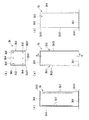
収納什器3は、テーブル什器2の左側端部2d(左右方向の端部)に当接された状態で配置されている。図2は、収納什器3の概略構成を示す4面図であり、(a)が図1における左側から見た正面図、(b)が平面図、(c)が図1における後側から見た側面図、(d)が図1における前側から見た側面図である。また、図3は、収納什器3の概略構成を示す背面図であり、図1における右側から見た図である。
The
これらの図に示すように、収納什器3は、ブリッジベース3aと、第1箱体3bと、第1棚板3cと、第2箱体3dと、第2棚板3eと、ブリッジ天板3fと、背面パネル3gと、ブリッジ棚板3hとを備えている。また、収納什器3は、部材同士の連結や、部材の支持に用いられる複数のビス(不図示)及びブラケット(不図示)等を備えている。
As shown in these drawings, the
ブリッジベース3aは、収納什器3の底部に配置された矩形のプレート状の部材であり、第1箱体3b、第2箱体3d及び背面パネル3gを下方から直接支持すると共に、第1棚板3c、第2棚板3e、ブリッジ天板3f及びブリッジ棚板3hとを間接的に支持している。このブリッジベース3aは、床面に直接当接する不図示のアジャスタを多数備えており、これらのアジャスタによって床面に対する姿勢を調節可能とされている。
The
第1箱体3bは、前側が開口された箱状の部材であり、ブリッジベース3aの前寄りに配置され、ブリッジベース3aと不図示のビスによって固定されている。図4は、第1箱体3bの概略構成を示す4面図であり、(a)が図1における前側から見た正面図、(b)が平面図、(c)が(a)のA−A線断面図、(d)が図1の右側方向から見た側面図である。また、図5は、第1箱体3bの背面図であり、図1の後方向から見た図である。これらの図に示すように、第1箱体3bは、底部3b1、第1側面部3b2、第2側面部3b3、背面部3b4及び天井部3b5から構成されている。
The
底部3b1は、図1における左右方向の幅が、ブリッジベース3aの幅と一致された矩形状のパネル部材であり、第1箱体3bの最下部に配置される。第1側面部3b2は底部3b1の左辺と接続されるパネル部材であり、第2側面部3b3は底部3b1の右辺と接続されるパネル部材であり、背面部3b4は底部3b1の後辺と接続されるパネル部材である。なお、第1側面部3b2と背面部3b4とは屈曲状態で接続され、第2側面部3b3と背面部3b4とも屈曲状態で接続されている。天井部3b5は、外形形状が底部3b1と同じパネル部材であり、第1側面部3b2と、第2側面部3b3と、背面部3b4との上端に接続され、第1箱体3bの最上部に配置されている。また、天井部3b5の天面には、天井部3b5とブリッジ天板3fとを接続するビスが挿通されるビス孔3b6が複数設けられている。
The bottom portion 3b1 is a rectangular panel member whose width in the left-right direction in FIG. 1 coincides with the width of the
第1側面部3b2と、第2側面部3b3と、背面部3b4とは、いずれも同じ高さ寸法を有している。これらの高さ寸法は、テーブル什器2の天板2cの設置高さを超えるように設定されている。また、図4(c)に示すように、第2側面部3b3の内壁には、第1棚板3cを不図示の棚ブラケットによって引っ掛けるための孔3b7が上下方向に配列されて複数設けられている。また、図示していないが、第1側面部3b2の内壁にも、第1棚板3cを不図示の棚ブラケットによって引っ掛けるための孔3b7が上下方向に配列されて複数設けられている。また、図5に示すように、背面部3b4の背面には、ブリッジ棚板3hを不図示の棚ブラケットによって引っ掛けるための孔3b8が上下方向に配列されて複数設けられている。
The first side surface portion 3b2, the second side surface portion 3b3, and the back surface portion 3b4 all have the same height. These height dimensions are set so as to exceed the installation height of the
このような第1箱体3bは、底部3b1の前縁3b11と、第1側面部3b2の前縁3b21と、第2側面部3b3の前縁3b31と、天井部3b5の前縁3b51とが同一仮想平面上に配置されている。すなわち、底部3b1の前縁3b11と、第1側面部3b2の前縁3b21と、第2側面部3b3の前縁3b31と、天井部3b5の前縁3b51とが面一となるように配置されている。
In such a
また、第1箱体3bは、これらの底部3b1の前縁3b11と、第1側面部3b2の前縁3b21と、第2側面部3b3の前縁3b31と、天井部3b5の前縁3b51とが配置される仮想平面を、テーブル什器2の天板2cの前側端部2c4と面一となるように配置されている。すなわち、図1に示す前後方向において、天板2cの前側端部2c4と収納什器3の前側端部(前縁3b11、前縁3b21、前縁3b31及び前縁3b51)との位置が一致されている。
The
また、第1箱体3bの内部は、ワーカーの所有物を収納する収納空間とされている。すなわち、収納什器3は、図1に示すように、第1箱体3bによって形成され、収納什器3において前方側に配置されると共に天板2cの前方側に向けて開口される第1収納部10を備えている。
Moreover, the inside of the
第1棚板3cは、第2側面部3b3の内壁に設けられた孔3b7に引っ掛けられる不図示の棚ブラケットによって支持されることで第1箱体3bの内部に配置されるパネル部材であり、第1収納部10の収納空間を上下方向に分割する。第1棚板3cは、第1収納部10の構成部材であり、本実施形態においては、上下方向に離間して2枚設置されている。これらの第1棚板3cによって、第1収納部10の収納空間が上下方向に3分割されている。
The
第2箱体3dは、図1の前後方向において第1箱体3bと対象形状とされているため、詳細な説明は省略する。このような第2箱体3dは、ブリッジベース3aの後寄りに配置され、ブリッジベース3aと不図示のビスによって固定されている。また、第2箱体3dは、図1に示す前後方向において、天板2cの後側端部2c5と収納什器3の後側端部との位置が一致されている。
Since the
このような第2箱体3dの内部は、ワーカーの所有物を収納する収納空間とされている。すなわち、収納什器3は、図1に示すように、第2箱体3dによって形成され、収納什器3において後方側に配置されると共に天板2cの後方側に向けて開口される第2収納部20を備えている。
The interior of the
第2棚板3eは、第2箱体3dの内部に配置されるパネル部材であり、第2収納部20の収納空間を上下方向に分割する。第2棚板3eは、第2収納部20の構成部材であり、本実施形態においては、上下方向に離間して2枚設置されている。これらの第2棚板3eによって、第2収納部20の収納空間が上下方向に3分割されている。
The
ブリッジ天板3fは、図1及び図2に示すように、第1箱体3bの天面3baと、第2箱体3dの天面3daとに固定されたパネル部材である。このブリッジ天板3fは、上方から見てブリッジベース3aと同じ矩形に形状設定されており、第1箱体3bと第2箱体3dとに架設されている。このようなブリッジ天板3fは、上面3f1が平面とされており、この上面3f1によって物品載置面とされている。また、このようなブリッジ天板3fは、第1箱体3b及び第2箱体3dを連結しており、収納什器3を一体化させている。
As shown in FIGS. 1 and 2, the
背面パネル3gは、ブリッジベース3aのテーブル什器2側の縁部に立設されたパネル部材である。この背面パネル3gは、図1の前後方向の幅寸法が第1箱体3bと第2箱体3dとの離間寸法に合わせられ、上下方向の高さ寸法が第1箱体3b及び第2箱体3dの高さ寸法と一致されており、ブリッジベース3aと、第1箱体3bと、第2箱体3dと、ブリッジ天板3fとによって囲まれた領域を、テーブル什器2側の縁部において塞ぐものである。
The
このようなブリッジベース3aと、第1箱体3bと、第2箱体3dと、ブリッジ天板3fと、背面パネル3gとによって囲まれた空間は、ワーカーの所有物を収納する収納空間とされている。すなわち、収納什器3は、図1に示すように、第1箱体3bと第2箱体3dとに挟まれて形成されると共に、テーブル什器2の天板2cと反対方向に向けて開口する第3収納部30を備えている。
The space surrounded by the
ブリッジ棚板3hは、第1箱体3bと第2箱体3dとに挟まれた空間に配置されるパネル部材であり、第3収納部30の収納空間を上下方向に分割する。ブリッジ棚板3hは、第3収納部30の構成部材であり、本実施形態において、上下方向に離間して2枚設置されている。これらのブリッジ棚板3hによって、第3収納部30の収納空間が上下方向に3分割されている。
The
収納什器4は、図1に示すように、テーブル什器2の右側端部2e(左右方向の端部)に当接された状態で配置されている。この収納什器4は、収納什器3と図1における左右方向において対称形状とされているため、詳細な説明については省略する。
As shown in FIG. 1, the storage fixture 4 is disposed in contact with the
なお、図1に示すように、収納什器3及び収納什器4は、天板2cの設置高さを超える高さ寸法を有し、天板2c側の面であって天板2cの上に露出された領域が情報掲示部3i及び情報掲示部4iとされている。この情報掲示部3i及び情報掲示部4iにおいては、例えばマグネットや粘着テープによってメモを貼付したり、また情報表示用のディスプレイを配置したりすることで容易に情報の掲示を行うことができる。
In addition, as shown in FIG. 1, the
図6は、連結材5を示す図であり、(a)が正面図、(b)が平面図、(c)が側面図である。これらの図に示すように、連結材5は、ベースプレート5aと、天板連結部5bとによって構成されている。ベースプレート5aは、収納什器3及び収納什器4の背面にビス止めにて固定される部位である。天板連結部5bは、ベースプレート5aの上端に対して2つ設けられており、ベースプレート5aに対して屈曲状態で接続されている。この天板連結部5bは、長さ寸法がテーブル什器2の脚体2a及び脚体2bの厚み寸法よりも大きく設定されている。このような天板連結部5bは、脚体2aと天板2cとの接続箇所(あるいは脚体2bと天板2cとの接続箇所)に設けられた孔部6に挿通され、先端が天板2cの裏面にビス止めされている。このような連結材5は、図3に示すように、収納什器3に対して2つ設置されている。これらの連結材5によって収納什器3とテーブル什器2とが連結されている。また、収納什器4も、同様に2つの連結材5によってテーブル什器2と連結されている。
6A and 6B are views showing the connecting
このような構成を有する本実施形態のワークステーション装置1においては、左右寸法が前後寸法よりも長尺な天板2cを有するテーブル什器2と、天板2cの左右方向における端部に当接されて配置されると共に、天板2cの前方に向けて開口する第1収納部10、天板2cの後方に向けて開口する第2収納部20、及び、天板2cと反対方向に向けて開口する第3収納部30を有する収納什器3(及び収納什器4)とを備えている。このような本実施形態のワークステーション装置1によれば、テーブル什器2に対して収納什器3及び収納什器4が併設されているため、ワゴンを用いることなく個人の所有物を保管することが可能となる。このため、本実施形態のワークステーション装置1によれば、テーブル什器2における座席選択の自由度が損なわれることがない。
In the workstation apparatus 1 of this embodiment having such a configuration, the table fixture 2 having a
また、本実施形態のワークステーション装置1によれば、第1収納部10がテーブル什器2の天板2cの前方に向けて開口されており、第2収納部20がテーブル什器2の天板2cの後方に向けて開口されており、第3収納部30がテーブル什器2の天板2cと反対方向に向けて開口されている。このため、天板2cの前方に着座するワーカーは、第1収納部10に容易に荷物を出し入れすることができ、天板2cの後方に着座するワーカーは、第2収納部20に容易に荷物を出し入れすることができ、第3収納部30は、天板2cの前方及び後方のどちら側に着座するワーカーでも荷物の出し入れを行うことができる。したがって、本実施形態のワークステーション装置1は、使い勝手の良いものとなっている。
Moreover, according to the workstation apparatus 1 of this embodiment, the
また、本実施形態のワークステーション装置1においては、第1収納部10が、前方側に配置されると共に前方側が開口された第1箱体3bと、この第1箱体3bの内部に設置される第1棚板3cとを備え、第2収納部20が、後方側に配置されると共に後方側が開口された第2箱体3dと、この第2箱体3dの内部に設置される第2棚板3eとを備え、第3収納部30が、第1箱体3bと第2箱体3dとに挟まれた空間にブリッジ棚板3hを設置することにより形成されている。このような本実施形態のワークステーション装置1によれば、第3収納部30の一部が第1収納部10の第1箱体3bと第2収納部20の第2箱体3dによって形成されている。このため、第3収納部30の構成要素を削減し、収納什器3及び収納什器4(さらにはワークステーション装置1自体)を簡易的にかつ安価に構成することができる。
Moreover, in the workstation apparatus 1 of this embodiment, the
また、本実施形態のワークステーション装置1においては、第1箱体3bの天面3baと第2箱体3dの天面3daとに固定されるブリッジ天板3fを備えている。第1箱体3bと第2箱体3dとに架設されたブリッジ天板3fの上面3f1が物品の載置面となる。このため、簡易的な構造で広い物品載置面を有する収納什器3及び収納什器4とすることができる。また、ブリッジ天板3fによって第1箱体3bと第2箱体3dとが連結されるため、収納什器3及び収納什器4の全体が一体化され、収納什器3及び収納什器4の強度を高めることが可能となる。
Further, the workstation device 1 of the present embodiment includes a
本実施形態のワークステーション装置1においては、図1における前後方向において、天板2cの前側端部と収納什器3及び収納什器4の前側端部との位置が一致され、かつ、天板2cの後側端部と収納什器3及び収納什器4の後側端部との位置が一致されている。このため、本実施形態のワークステーション装置1によれば、テーブル什器2と収納什器3との境界部分に前後方向に凹凸ができることを防止することができ、ワークステーション装置1の前後端に凹凸が形成されず、使い勝手を良好なものとすることができる。
In the workstation device 1 of the present embodiment, the positions of the front end of the
また、本実施形態のワークステーション装置1においては、収納什器3及び収納什器4が、天板2cの設置高さを超える高さ寸法を有し、天板2c側の面であって天板2cの上に露出された領域が情報掲示部3i及び情報掲示部4iとされている。このような本実施形態のワークステーション装置1によれば、収納什器3及び収納什器4の開口が設けられない面の上部が情報掲示部3i及び情報掲示部4iとして用いられる。このため、容易にワーカーが情報を共有することができ、ワークステーション装置1としての使い勝手が向上する。また、天板2c上の側方が収納什器3及び収納什器4によって閉塞されることになるため、作業空間とその他の空間とを区画することが出来ると共に、作業者の視線を遮ることによって好適な作業空間を形成することが出来る。
Moreover, in the workstation apparatus 1 of this embodiment, the
以上、添付図面を参照しながら本発明の好適な実施形態について説明したが、本発明は、上記実施形態に限定されないことは言うまでもない。上述した実施形態において示した各構成部材の諸形状や組み合わせ等は一例であって、本発明の趣旨から逸脱しない範囲において設計要求等に基づき種々変更可能である。 As mentioned above, although preferred embodiment of this invention was described referring an accompanying drawing, it cannot be overemphasized that this invention is not limited to the said embodiment. Various shapes, combinations, and the like of the constituent members shown in the above-described embodiments are examples, and various modifications can be made based on design requirements and the like without departing from the spirit of the present invention.
例えば、上記実施形態においては、テーブル什器2の両側に対して収納什器(収納什器3及び収納什器4)が設置された構成について説明した。しかしながら、本発明はこれに限定されるものではなく、テーブル什器2のいずれか片側に対してのみ収納什器を設置するようにしても良い。
For example, in the above-described embodiment, the configuration in which the storage fixtures (the
また、上記実施形態においては、各収納部(第1収納部10、第2収納部20及び第3収納部30)が2枚ずつの棚板(第1棚板3c、第2棚板3e及びブリッジ棚板3h)を備える構成について説明した。しかしながら、本発明はこれに限定されるものではなく、棚板の枚数は任意であり、また棚板を設置しない構成を採用することも可能である。
Moreover, in the said embodiment, each storage part (the
また、上記実施形態においては、テーブル什器2の天板2cが脚体2a及び脚体2bによって支持された構成について説明した。しかしながら、本発明はこれに限定されるものではなく、中央に配置される1つの脚体で天板2cを支持する構成や、収納什器3及び収納什器4で天板2cを支持して脚体を削除する構成を採用することもできる。
Moreover, in the said embodiment, the structure by which the
また、上記実施形態においては、テーブル什器2と収納什器3及び収納什器4とが連結材5にて連結されている構成について説明した。しかしながら、本発明はこれに限定されるものではなく、テーブル什器2と収納什器3及び収納什器4とが係合して連結される構成や、テーブル什器2と収納什器3及び収納什器4とが当接のみする構成を採用することも可能である。
Moreover, in the said embodiment, the structure by which the table fixture 2, the
1……ワークステーション装置、2……テーブル什器、2a……脚体、2b……脚体、2c……天板、2c1……配線収容部、2c2……溝、2c3……カバー、2c4……前側端部、2c5……後側端部、2d……左側端部、2e……右側端部、3……収納什器、3a……ブリッジベース、3b……第1箱体、3b1……底部、3b11……前縁、3b2……第1側面部、3b21……前縁、3b3……第2側面部、3b31……前縁、3b4……背面部、3b5……天井部、3b51……前縁、3b6……ビス孔、3b7……孔、3b8……孔、3ba……天面、3c……第1棚板、3d……第2箱体、3da……天面、3e……第2棚板、3f……ブリッジ天板、3f1……上面、3g……背面パネル、3h……ブリッジ棚板、3i……情報掲示部、4……収納什器、4i……情報掲示部、5……連結材、5a……ベースプレート、5b……天板連結部、6……孔部、10……第1収納部、20……第2収納部、30……第3収納部 DESCRIPTION OF SYMBOLS 1 ... Workstation apparatus, 2 ... Table fixture, 2a ... Leg, 2b ... Leg, 2c ... Top plate, 2c1 ... Wiring accommodating part, 2c2 ... Groove, 2c3 ... Cover, 2c4 ... ... front end, 2c5 ... rear end, 2d ... left end, 2e ... right end, 3 ... storage fixture, 3a ... bridge base, 3b ... first box, 3b1 ... Bottom part, 3b11 ... Front edge, 3b2 ... First side part, 3b21 ... Front edge, 3b3 ... Second side part, 3b31 ... Front edge, 3b4 ... Back part, 3b5 ... Ceiling part, 3b51 ... ... front edge, 3b6 ... screw hole, 3b7 ... hole, 3b8 ... hole, 3ba ... top surface, 3c ... first shelf, 3d ... second box, 3da ... top surface, 3e ... ... 2nd shelf board, 3f ... Bridge top board, 3f1 ... Upper surface, 3g ... Back panel, 3h ... Bridge shelf board, 3i ... Information display part, 4 …… Storage fixture, 4i …… Information display part, 5 …… Connecting material, 5a …… Base plate, 5b …… Top plate connection part, 6 …… Hole part, 10 …… First storage part, 20 …… Second storage part, 30 …… Third storage part
Claims (4)
前記天板の左右方向における端部に当接されて配置されると共に、前記天板の前方に向けて開口する第1収納部、前記天板の後方に向けて開口する第2収納部、及び、前記天板と反対方向に向けて開口する第3収納部を有する収納什器と
を備え、
前記第1収納部が前方側に配置される第1箱体を有し、前記第2収納部が後方側に配置される第2箱体を有し、
前記第1箱体の天面と前記第2箱体の天面とに固定されるブリッジ天板をさらに備える
ことを特徴とするワークステーション装置。 A table fixture having a top plate whose left-right dimension is longer than the front-rear dimension;
A first storage portion that is disposed in contact with an end portion of the top plate in the left-right direction and that opens toward the front of the top plate; a second storage portion that opens toward the rear of the top plate; and A storage fixture having a third storage portion that opens in a direction opposite to the top plate ,
The first storage part has a first box disposed on the front side, and the second storage part has a second box disposed on the rear side,
The workstation apparatus further comprising a bridge top plate fixed to the top surface of the first box and the top surface of the second box .
前記第2収納部は、後方側に配置されると共に後方側が開口された前記第2箱体と、当該第2箱体の内部に設置される棚板とを備え、
前記第3収納部は、前記第1箱体と前記第2箱体とに挟まれた空間に棚板を設置することにより形成されている
ことを特徴とする請求項1記載のワークステーション装置。 The first housing portion includes a first box body front side is opened while being disposed on the front side, and a shelf board that is installed inside of the first box body,
It said second housing portion comprises said second box body rear side is opened while being disposed on the rear side, and a shelf board that is installed inside of the second box body,
The workstation device according to claim 1, wherein the third storage unit is formed by installing a shelf board in a space sandwiched between the first box and the second box.
Priority Applications (1)
| Application Number | Priority Date | Filing Date | Title |
|---|---|---|---|
| JP2012243853A JP6166885B2 (en) | 2012-11-05 | 2012-11-05 | Workstation equipment |
Applications Claiming Priority (1)
| Application Number | Priority Date | Filing Date | Title |
|---|---|---|---|
| JP2012243853A JP6166885B2 (en) | 2012-11-05 | 2012-11-05 | Workstation equipment |
Publications (2)
| Publication Number | Publication Date |
|---|---|
| JP2014090919A JP2014090919A (en) | 2014-05-19 |
| JP6166885B2 true JP6166885B2 (en) | 2017-07-19 |
Family
ID=50935442
Family Applications (1)
| Application Number | Title | Priority Date | Filing Date |
|---|---|---|---|
| JP2012243853A Active JP6166885B2 (en) | 2012-11-05 | 2012-11-05 | Workstation equipment |
Country Status (1)
| Country | Link |
|---|---|
| JP (1) | JP6166885B2 (en) |
Families Citing this family (1)
| Publication number | Priority date | Publication date | Assignee | Title |
|---|---|---|---|---|
| JP6788483B2 (en) * | 2016-11-24 | 2020-11-25 | 株式会社くろがね工作所 | Combination desk |
Family Cites Families (4)
| Publication number | Priority date | Publication date | Assignee | Title |
|---|---|---|---|---|
| JPH03258211A (en) * | 1990-03-09 | 1991-11-18 | Toshihiro Shiyouko | Cabinet arrangement |
| US5058964A (en) * | 1990-06-07 | 1991-10-22 | Haworth, Inc. | Storage cabinet-worksurface arrangement |
| JP4553347B2 (en) * | 2003-11-11 | 2010-09-29 | 株式会社岡村製作所 | Storage furniture |
| JP2010022670A (en) * | 2008-07-22 | 2010-02-04 | Okamura Corp | Shelf device and combination furniture of shelf device and desk |
-
2012
- 2012-11-05 JP JP2012243853A patent/JP6166885B2/en active Active
Also Published As
| Publication number | Publication date |
|---|---|
| JP2014090919A (en) | 2014-05-19 |
Similar Documents
| Publication | Publication Date | Title |
|---|---|---|
| JP6838716B2 (en) | Top plate elevating desk | |
| JP6166885B2 (en) | Workstation equipment | |
| JP2021087801A (en) | Top plate lift type furniture, reception member for top plate | |
| JP6140424B2 (en) | Workstation equipment | |
| JP2020065877A (en) | Article stand | |
| JP6692143B2 (en) | Storage box suspension structure | |
| JP6288817B2 (en) | Article storage unit, fixture system | |
| JP2003339450A (en) | Desk and desk system | |
| JP5879137B2 (en) | Desk equipment | |
| JP6920073B2 (en) | table | |
| JP5934492B2 (en) | Desk equipment | |
| JP6882142B2 (en) | Furniture system | |
| JP6327599B2 (en) | Table system | |
| JP2008295918A (en) | Storage furniture | |
| JP5957203B2 (en) | Desk equipment | |
| JP6124553B2 (en) | desk | |
| KR20190131173A (en) | Desk tidies for arranging goods | |
| JP7240849B2 (en) | electronics stand | |
| JP6985106B2 (en) | Desktop panel structure | |
| JP2024058309A (en) | Fixtures System | |
| JP6558712B1 (en) | Double top desk | |
| JP2022033611A (en) | desk | |
| JP6725410B2 (en) | Wiring housing fixture | |
| KR20170140970A (en) | Desk body frame | |
| JP5672438B2 (en) | Furniture with a top board with curtains |
Legal Events
| Date | Code | Title | Description |
|---|---|---|---|
| A621 | Written request for application examination |
Free format text: JAPANESE INTERMEDIATE CODE: A621 Effective date: 20151104 |
|
| A977 | Report on retrieval |
Free format text: JAPANESE INTERMEDIATE CODE: A971007 Effective date: 20160912 |
|
| A131 | Notification of reasons for refusal |
Free format text: JAPANESE INTERMEDIATE CODE: A131 Effective date: 20161011 |
|
| A521 | Request for written amendment filed |
Free format text: JAPANESE INTERMEDIATE CODE: A523 Effective date: 20161208 |
|
| TRDD | Decision of grant or rejection written | ||
| A01 | Written decision to grant a patent or to grant a registration (utility model) |
Free format text: JAPANESE INTERMEDIATE CODE: A01 Effective date: 20170530 |
|
| A61 | First payment of annual fees (during grant procedure) |
Free format text: JAPANESE INTERMEDIATE CODE: A61 Effective date: 20170626 |
|
| R150 | Certificate of patent or registration of utility model |
Ref document number: 6166885 Country of ref document: JP Free format text: JAPANESE INTERMEDIATE CODE: R150 |
|
| S533 | Written request for registration of change of name |
Free format text: JAPANESE INTERMEDIATE CODE: R313533 |
|
| R350 | Written notification of registration of transfer |
Free format text: JAPANESE INTERMEDIATE CODE: R350 |
|
| R250 | Receipt of annual fees |
Free format text: JAPANESE INTERMEDIATE CODE: R250 |
|
| R250 | Receipt of annual fees |
Free format text: JAPANESE INTERMEDIATE CODE: R250 |
|
| R250 | Receipt of annual fees |
Free format text: JAPANESE INTERMEDIATE CODE: R250 |
|
| R250 | Receipt of annual fees |
Free format text: JAPANESE INTERMEDIATE CODE: R250 |