US11831065B2 - Antenna support system and method of installing the same - Google Patents
Antenna support system and method of installing the same Download PDFInfo
- Publication number
- US11831065B2 US11831065B2 US16/653,163 US201916653163A US11831065B2 US 11831065 B2 US11831065 B2 US 11831065B2 US 201916653163 A US201916653163 A US 201916653163A US 11831065 B2 US11831065 B2 US 11831065B2
- Authority
- US
- United States
- Prior art keywords
- mast
- antenna
- clamp
- cellular antenna
- cellular
- Prior art date
- Legal status (The legal status is an assumption and is not a legal conclusion. Google has not performed a legal analysis and makes no representation as to the accuracy of the status listed.)
- Active, expires
Links
Images


Classifications
-
- H—ELECTRICITY
- H01—ELECTRIC ELEMENTS
- H01Q—ANTENNAS, i.e. RADIO AERIALS
- H01Q1/00—Details of, or arrangements associated with, antennas
- H01Q1/12—Supports; Mounting means
-
- H—ELECTRICITY
- H01—ELECTRIC ELEMENTS
- H01Q—ANTENNAS, i.e. RADIO AERIALS
- H01Q1/00—Details of, or arrangements associated with, antennas
- H01Q1/12—Supports; Mounting means
- H01Q1/125—Means for positioning
- H01Q1/1264—Adjusting different parts or elements of an aerial unit
-
- H—ELECTRICITY
- H01—ELECTRIC ELEMENTS
- H01Q—ANTENNAS, i.e. RADIO AERIALS
- H01Q1/00—Details of, or arrangements associated with, antennas
- H01Q1/12—Supports; Mounting means
- H01Q1/125—Means for positioning
-
- H—ELECTRICITY
- H01—ELECTRIC ELEMENTS
- H01Q—ANTENNAS, i.e. RADIO AERIALS
- H01Q1/00—Details of, or arrangements associated with, antennas
- H01Q1/12—Supports; Mounting means
- H01Q1/1207—Supports; Mounting means for fastening a rigid aerial element
- H01Q1/1221—Supports; Mounting means for fastening a rigid aerial element onto a wall
-
- H—ELECTRICITY
- H01—ELECTRIC ELEMENTS
- H01Q—ANTENNAS, i.e. RADIO AERIALS
- H01Q1/00—Details of, or arrangements associated with, antennas
- H01Q1/12—Supports; Mounting means
- H01Q1/1207—Supports; Mounting means for fastening a rigid aerial element
- H01Q1/1228—Supports; Mounting means for fastening a rigid aerial element on a boom
-
- H—ELECTRICITY
- H01—ELECTRIC ELEMENTS
- H01Q—ANTENNAS, i.e. RADIO AERIALS
- H01Q1/00—Details of, or arrangements associated with, antennas
- H01Q1/12—Supports; Mounting means
- H01Q1/1242—Rigid masts specially adapted for supporting an aerial
-
- H—ELECTRICITY
- H01—ELECTRIC ELEMENTS
- H01Q—ANTENNAS, i.e. RADIO AERIALS
- H01Q1/00—Details of, or arrangements associated with, antennas
- H01Q1/12—Supports; Mounting means
- H01Q1/22—Supports; Mounting means by structural association with other equipment or articles
- H01Q1/24—Supports; Mounting means by structural association with other equipment or articles with receiving set
- H01Q1/241—Supports; Mounting means by structural association with other equipment or articles with receiving set used in mobile communications, e.g. GSM
- H01Q1/246—Supports; Mounting means by structural association with other equipment or articles with receiving set used in mobile communications, e.g. GSM specially adapted for base stations
-
- H—ELECTRICITY
- H01—ELECTRIC ELEMENTS
- H01Q—ANTENNAS, i.e. RADIO AERIALS
- H01Q3/00—Arrangements for changing or varying the orientation or the shape of the directional pattern of the waves radiated from an antenna or antenna system
- H01Q3/02—Arrangements for changing or varying the orientation or the shape of the directional pattern of the waves radiated from an antenna or antenna system using mechanical movement of antenna or antenna system as a whole
- H01Q3/04—Arrangements for changing or varying the orientation or the shape of the directional pattern of the waves radiated from an antenna or antenna system using mechanical movement of antenna or antenna system as a whole for varying one co-ordinate of the orientation
- H01Q3/06—Arrangements for changing or varying the orientation or the shape of the directional pattern of the waves radiated from an antenna or antenna system using mechanical movement of antenna or antenna system as a whole for varying one co-ordinate of the orientation over a restricted angle
-
- H—ELECTRICITY
- H01—ELECTRIC ELEMENTS
- H01Q—ANTENNAS, i.e. RADIO AERIALS
- H01Q3/00—Arrangements for changing or varying the orientation or the shape of the directional pattern of the waves radiated from an antenna or antenna system
- H01Q3/02—Arrangements for changing or varying the orientation or the shape of the directional pattern of the waves radiated from an antenna or antenna system using mechanical movement of antenna or antenna system as a whole
- H01Q3/08—Arrangements for changing or varying the orientation or the shape of the directional pattern of the waves radiated from an antenna or antenna system using mechanical movement of antenna or antenna system as a whole for varying two co-ordinates of the orientation
Definitions
- the present disclosure relates to an improved antenna support system and method of installing the same. More specifically, the present disclosure is concerned with a system and method well suited to mounting modern cellular antennas to masts.
- the antennas had to be placed high from the ground in order to reduce the RF path-loss effects (or RF signal attenuation).
- the antennas also need to point in specific directions in the horizontal plane (i.e. at an azimuth angle about a vertical axis-alignment of the antenna directionality with respect to North) and in the vertical plane (i.e. tilt angle about an horizontal axis-alignment of the antenna directionality with respect to the earth's centre of gravity) in order to satisfy certain RF planning criteria for optimum coverage, capacity and quality of wireless communications.
- mast In order to install antennas at a specified height from the ground, mobile communication networks worldwide adopted the engineering and design of very well-known tower and mast types such as lattice and pole systems.
- the terms “mast” and “tower” are often used interchangeably, and it is to be understood that the term “mast” is used in this application to cover both masts and towers.
- a tower is a self-supporting or cantilevered structure, while a mast is held up by stays or guys.
- the self-supported lattice is the most widespread form of construction. It provides high strength, low weight and low wind resistance, and is economic in its use of materials. Lattices of triangular cross-section are most common, and square lattices are also widely used. Guyed lattice masts are also often used; the supporting guy lines carry lateral forces such as wind loads, allowing the mast to be very narrow and of modular construction. The entire structure is constructed by creating a series of horizontal ladders, or internal triangular structures, that secure the tower's three, or four base legs. Guyed masts are also constructed out of steel tubes.
- monopole rooftop masts (which may be covered with camouflage and/or a radome) have been installed on top of many buildings.
- developers wanted a more efficient way to construct and operate low-height elevation systems for aesthetic reasons. They conceived the idea of the monopole rooftop configuration, a lattice mast with a pole on top used for antenna mounting. These configurations became more fashionable, once alternative construction materials began to exhibit greater strength and flexibility without failing. Today these free-standing masts are fabricated from various materials.
- the antenna tilt bracket is a standard antenna accessory, delivered with the specific antenna purchased, and as such we will not further describe the various types of tilt bracket here.
- the most common type of antenna azimuth bracket in the field comprises a set of collars that are mounted on one side at the antenna tilt bracket and on the other side are fixed on a pole. Azimuth alignment is performed by loosening the collars, aligning the antenna and tightening the collars on the pole. More sophisticated antenna azimuth brackets are described in detail in the applicant's related co-pending International Patent Application No. PCT/EP2018/083707, filed Dec. 5, 2018, and published as WO2019/110697, the content of which is incorporated by reference herein in its entirety.
- Radio coverage of each antenna needs to be decided according to radio planning criteria.
- each directional antenna needs to be capable of 120 degrees azimuth and 20 degrees tilt range (10 degrees up-tilt and 10 degrees down-tilt). Even fully equipped with both azimuth and tilt brackets, an antenna cannot be directly installed on the mast structure and still be capable of full movement in both azimuth and tilt directions.
- the main reason for that is the fact that modern cellular antenna geometry (panel type) are bulky, long (may reach up to 3 meters length), wide (may be more than half a meter wide) and heavy (may weigh more than 50 kgs); not to be mentioned that over a dozen coaxial cables are mounted on the bottom of the antenna that cannot be over-bended, especially when the antenna is to be down-tilted.
- the antenna always needs to be mounted on a mast's structural member that is of circular shape, is capable of supporting the excessive weight and wind-load and of course has the required clearance from other antennas and the structure itself for azimuth alignment according to radio planning instructions.
- Using such poles for the purpose is not only expensive but also impractical (most of the times impossible) to implement. The situation is complicated further when the pole is to be supported by wires.
- Lattices of either triangular or rectangular cross-section may have 3 or 4 vertical upright structural members (of various shapes such as equal angles, hollows and the like) that are mounted together with multiple horizontal and diagonal cross-members, spaced apart in sets (the number of which determines the mast height), so as forming the desired lattice mast configuration.
- FIG. 1 An example of a legacy antenna “support system” adopted by the industry is shown in FIG. 1 .
- a cellular antenna mast 2 comprising vertical upright members 4 , horizontal cross-members 6 and bracing members 8 .
- the mast 2 is a square-section lattice mast.
- a “mast member” is a component that is part of the mast. In other words, it is structurally integrated with the mast to the extent that removal would cause structural problems.
- “Mast members” include monopole rooftop masts installed on buildings, possibly on top of a lattice structure, but not e.g. poles attached to the side of an existing mast (as with legacy systems).
- the support system 10 comprises a pair of pole supports 12 , 14 .
- Each support 12 , 14 comprises a pair of elongate metal tubes 16 , 18 attached at a first end to the mast (specifically the upright members 4 ) and a pole clamp 20 at a second end.
- the supports 12 , 14 are attached to the mast at two spaced-apart vertical positions.
- An antenna pole 22 is inserted through the pole clamps of both supports, and defines an azimuth steering axis Z.
- the support system 10 is configured to allow the riggers to install the antenna at the desired azimuth and tilt direction.
- Antenna tilt brackets 26 , 28 are installed each on pole 22 .
- the antenna tilt brackets comprise collars 27 , 29 that clamp the pole 22 and permit selective rotation about the steering axis Z.
- the collars 27 , 29 of the mechanical tilt brackets can be tightened to inhibit antenna rotation about the azimuth steering axis.
- the mechanical tilt brackets 26 , 28 also rotate the antenna in the vertical plane (inclination).
- the antenna supports 12 , 14 and pole 22 are all machined hot-dipped galvanized steel that add considerable weight and wind-load to the mast and specifically at the tower-top.
- a typical legacy antenna support system weights 60 kg (i.e. for a typical 3 sector installation 180 kgs in total) while it adds an unnecessary (considerable compared to the antenna) effective projected area (EPA) to the antenna system.
- EPA effective projected area
- the extra weight negatively impacts the mean time between failure (MTBF) of the tower itself—not to mention that on marginal static cases (especially when RAN technology network upgrades are needed), expensive mast reinforcements are also required.
- the legacy antenna “support” also presents a negative environmental footprint (caused by the unnecessary galvanized steel deployed for antenna mounting). This unnecessary weight directly translates into increased CO 2 emissions into the environment.
- 5G technology itself is characterized by high energy consumption and there is a need for mobile network operators to reduce their environmental footprint.
- the legacy antenna “support” system installation is complex, as it needs to take place in three discrete phases:
- TCO total cost of ownership
- the aim of the present disclosure is to facilitate a quick and easy, lightweight, safer, environmentally friendly mounting of generally heavy and aerodynamically inefficient modern cellular antennas at the top of masts, whilst providing the same or greater functionality as legacy systems.
- a prior antenna mounting bracket is disclosed in U.S. Pat. No. 9,437,918.
- US′918 discloses a bracket with adjustable azimuth settings coupled to a “support structure”.
- the bracket has a pivot rod about which a moveable bracket assembly is rotatable via a gearbox.
- the moveable bracket assembly can be locked with locking pins.
- the backplate of the bracket may be attached to a platform associated with a base station tower.
- the need for such a “platform” (akin to the support structure of the prior art) and the provision of a single bracket that spans the entire height of the antenna demonstrates that this particular device exhibits all of the aforementioned problems with the prior art.
- an antenna support system comprising:
- a universal clamp kit having:
- a mast clamp and steering and locking unit allows the antenna to be placed closer to the mast itself, reducing the wind loading moment. Furthermore, the use of a clamp and steering unit is less bulky and heavy than the prior art support bracket and pole arrangement.
- the first and second shapes of antenna mast section are selected from: a square section, a planar section, an angle section and a circular section.
- At least the first clamp engages with the first shape of antenna mast section such that the first clamp cannot be rotated relative to the first shape of antenna mast section.
- the first universal clamp plate is attachable to a wall.
- azimuth steering unit comprises a housing containing a rotational joint.
- the rotational joint may comprise a rolling element bearing or bushing.
- the azimuth steering unit preferably comprises a locking mechanism configured to mechanically lock the steering unit at a predetermined angle.
- the locking mechanism comprises a locking plate and a locking member engageable with the locking plate to thereby lock the steering unit.
- the locking plate may comprise a plurality of openings or a ratchet and pawl mechanism to facilitate locking.
- the unit may be the same as or similar to the applicant's steering and locking unit disclosed in WO2013/171291 or WO 2019/110697.
- first and second clamps are configured to support an antenna by virtue of mechanical friction with the first or second shapes of mast sections respectively.
- an antenna support system comprising the steps of:
- a mast and cellular antenna comprising:
- the method comprises the steps of:
- the method comprises the steps of:
- the method comprises the steps of:
- the step of locking takes place before a step of elevating the antenna to the required height.
- the assembly comprises two spaced-apart support brackets, and wherein the pole extends between the support brackets.
- the method comprises:
- the symmetry of the steering unit fixing holes 120 along with the symmetry of the azimuth steering unit locking plate 104 , ensures that the installed antenna will be tightly secured, collinearly on the mast's vertical structural member, as such the antenna reflector/backplane cannot be twisted when clamped on the mast.
- the “reference frame” method described in the applicant's earlier application WO2013/171291 is combined with the present disclosure.
- the mast member forms the reference frame.
- FIG. 1 is a perspective view of a prior art antenna mounting system and an antenna mounting system according to the disclosure on the same mast;
- FIGS. 2 a and 2 b are perspective views of a steering and locking unit for use with systems and methods of the present disclosure
- FIG. 3 is a first modular component in accordance with the present disclosure
- FIG. 4 is a second modular component in accordance with the present disclosure.
- FIG. 5 is a third modular component in accordance with the present disclosure.
- FIG. 6 is a fourth modular component in accordance with the present disclosure.
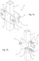
- FIGS. 7 a and 7 b are perspective views of a first antenna mounting bracket in accordance with the present disclosure.
- FIGS. 8 a and 8 b are perspective views of a second antenna mounting bracket in accordance with the present disclosure.
- FIGS. 9 a to 9 c are perspective views of a third antenna mounting bracket in accordance with the present disclosure.
- FIGS. 10 a , 10 b , and 10 c are perspective views of a fourth antenna mounting bracket in accordance with the present disclosure.
- FIGS. 11 a and 11 b are perspective views of a fifth antenna mounting bracket in accordance with the present disclosure.
- FIG. 12 is a perspective view of a first spacer for use with the systems and methods of the present disclosure
- FIG. 13 is a perspective view of a second spacer for use with the system and methods of the present disclosure.
- FIG. 14 is a perspective view of a third spacer for use with the systems and methods of the present disclosure.
- the unit 100 comprises a mast-side portion 102 , an antenna-side portion and a rotational joint 106 therebetween enabling the two portions 102 , 104 to be rotated relative to one another about an azimuth steering axis X.
- the mast-side portion has a pair of spaced-apart fixing holes 150 .
- brackets for attaching the steering and locking unit 100 (and therefore an antenna) to a range of structures.
- the different types of brackets are:
- the brackets form part of an antenna mounting kit or system, comprising various components common to one or more of the brackets. These components are:
- kit or system is modular—the common parts of the kit can be combined in different ways to attach antennas to different types of structure.
- Each bracket H, E, J, P is essentially an adaptor to clamp the relevant section of the structure and present a face for attachment of the steering and locking unit 100 .
- the clamps do not rely on drilling holes or openings in the underlying structure (with the exception of the W-type bracket for walls).
- the bracket plate 108 is a flat, rectangular plate 115 comprising a plurality of circular through-bores as described below.
- the plate 108 is symmetrical about a plane of symmetry P, coincident with a transverse axis T and normal to a long axis L.
- Each side has a plurality of fixing holes 116 divided into a first set 117 and a second set 118 .
- Each set 117 , 118 is in an “L” shape nested in a corner of the plate 115 .
- a pair of clamping holes 119 are provided on each side of the plate 108 , aligned along the plate's long axis L.
- Three steering unit fixing holes 120 are provided in a line parallel to, and offset from the transverse axis T.
- a pair of pole clamp plate fixing holes 121 are provided spaced along the transverse axis T.
- the back plate 110 is a flat, rectangular plate 122 .
- the plate is generally symmetrical about a plane of symmetry P′, coincident with a transverse axis T′ and normal to a long axis L′.
- a pair of pole clamp plate fixing holes 124 are provided spaced along the transverse axis T.
- a curved open slot 125 is provided, extending from the periphery.
- a clamping hole 126 is provided on the opposite side of the plate 110 .
- the pole clamp plate 112 shown in FIG. 5 is an elongate, prismatic component.
- the cross-section of the plate 112 has a base 127 and two opposing arms 128 , 129 providing a “U” shape.
- two fixing holes 130 At two spaced-apart positions on the base, spaced along the longitudinal axis of the plate, there are provided two fixing holes 130 .
- the pole clamp plate 112 can be a “plug-n-play” component to the bracket plate 108 and the Back plate 110 .
- the pole clamp plate 112 colinearly with a pole, it is ensured that the selected clamp configuration has the required surface contact with the pole so as the friction generated between the pole clamp plate and the pole is adequate to support both the weight and the wind loading of the installed antenna after installation on the mast.
- the contact surface area of the pole clamp plate 112 is at least ten times more than that of the prior art collar 27 , 29 found on the legacy antenna “support” system, ensuring that the novel support system of the present disclosure can withstand higher weight and wind-load than the legacy solutions.
- the angle section 114 comprises a first portion 131 and a second portion 132 at right angles to each other.
- the first portion 131 comprises a bore 133
- the second portion two spaced apart bores 134 , one close to the first portion than the other.
- the angle section 114 can be a “plug-n-play” component with the bracket plate 108 in order to form the H-type bracket 200 and the J-type bracket 400 (described below).
- the two spaced apart bores 134 can be fixed in pairs on the bore set 117 and the bore set 118 of the bracket plate 108 (2 ⁇ angle section 114 components are needed).
- the H-type bracket assembly shown in FIGS. 7 a and 7 b comprises a bracket plate 108 , a back plate 110 , two angle sections 114 , two clamp bolts 202 (with locking nuts 204 ) and several screws 206 with nuts 207 .
- the H-type bracket is used for square section mast members, such as upright member 4 in FIG. 1 .
- the square section mast member in FIGS. 7 a and 7 b is also labelled 4 , and referring to the right hand side of FIG. 1 is shown installed on the mast 2 .
- the angle sections 114 are attached to the bracket plate 108 with screws 206 passing through the bores 134 and fixing holes 116 in the first set 117 . They are secured with nuts. The angle sections 114 are then attached to the member 4 in order to align the bracket plate 108 on the mast's vertical structural member and ensure the symmetry of the steering unit fixing holes 120 , along with the symmetry of the azimuth steering unit locking plate 104 . In this way, the installed antenna can be tightly secured, collinearly on the mast's vertical structural member, as such the antenna reflector/backplane cannot be twisted when clamped on the mast.
- the back plate 110 is positioned on an opposite side of the member 4 to the bracket plate 108 .
- a first clamping bolt 202 is fed through a clamping hole 119 of the bracket plate and the aligned clamping hole 126 of the back plate.
- a second clamping bolt 202 is fed through a second clamping hole 119 of the bracket plate and the aligned clamping slot 125 of the back plate.
- the locking nuts 204 are used to tension the bolts 202 and thereby produce a clamping force on the member 4 to secure the bracket 200 in position. It will be noted that the attachment of the angle sections 114 to the member 4 is merely for alignment purposes, and is not intended to support any load (this is supported by the clamping force/friction of the bracket 200 ).
- the steering and locking unit 100 is attached to the bracket plate 108 by securing fasteners through the spaced-apart fixing holes 150 of the unit 100 and the steering unit fixing holes 120 . It should be noted that the attachment of the unit 100 to the plate 108 takes place before the plate 108 is assembled with the rest of the bracket 200 to clamp the member 4 .
- the horizontal length of the azimuth steering and locking unit 100 enables the position of the antenna to be offset the mast.
- an antenna of around three meter height and half a meter width can be placed spaced apart from the mast section on the horizontal plane in order to achieve azimuth steering of 120° range and tilt inclination of 20° range (up-tilt or down-tilt) without clashing on the mast structural members.
- the novel antenna support system of the present disclosure is simple and fast, and can take place in one discrete phase.
- the new antenna support system H-type bracket configuration
- the new antenna support system is installed on the antenna along with its azimuth steering units 100 and tilt brackets 26 , 28 on the ground.
- the steering angle can be selected and “locked in” before the assembly is taken up the mast to the appropriate height. Once installed, the antenna azimuth alignment is correct. This is clearly desirable due to the small amount of time it takes the riggers to perform such an installation. Smaller times of specialized personnel (like riggers) on tower-top, positively impacts installation costs, revenues (decreased site-down-time), health and safety at work.
- the idea of alignment with respect to a “reference frame” was introduced in applicant's earlier application WO2013/171291. This idea can be combined with the embodiments described herein to solve some of the above-mentioned problems with the prior art.
- the orientation of the mast member can be measured to a high degree of accuracy.
- the required steering angle can then be determined to achieve the desired antenna heading.
- the steering angle can be “locked in” using the steering and locking unit on the ground (pre-assembled with the antenna and bracket 200 ) before installation. Therefore when the rigger installs the antenna by attaching the bracket 200 as described above, the antenna heading will be correct, eliminating any error.
- the idea of alignment with respect to a “reference frame” as introduced in applicant's earlier application WO2013/171291 is applied to all mounting brackets disclosed in the present disclosure.
- the H-bracket design shown in FIGS. 7 a and 7 b can be modified to fit a range of sizes of square section members 4 . This can be facilitated by positioning the angle section 114 appropriately. For example, for a larger square section than shown in FIGS. 7 a and 7 b , the angle sections 114 can be attached to the bracket plate 108 at positions further towards the edge—i.e. in a different pair of the holes 117 , 118 . Therefore, a range of square sections—for example 60 ⁇ 60 mm, 70 ⁇ 70 mm, 80 ⁇ 80 mm can be accommodated.
- a pair of H-type brackets 200 spaced along the mast with respective azimuth steering units 100 weighs less than 10 Kg in total.
- the tower-top can be relieved of more than 50 Kgs of unnecessary weight per antenna.
- This H-type bracket advantage positively impacts the mean time between failure (MTBF) of the tower itself—not to mention that on marginal static cases (especially when RAN technology network upgrades are needed), expensive mast reinforcements can be avoided and CO 2 emissions into the environment can be significantly minimized.
- the E-type bracket is used for angle sections such as the member 301 in FIGS. 8 a and 8 b.
- the E-type bracket assembly shown in FIGS. 8 a and 8 b comprises four bracket plates 108 , two outer angle plates 302 , two inner angle plates 304 , a plurality of attachment screws 306 and two clamping bolts 308 with associated locking nuts 310 .
- Two of the plates 108 are attached using two spaced-apart outer angle plates 302 ( FIG. 8 a ) using screws 306 through the plates 302 and two of the respective first set 117 and second set 118 of fixing holes 116 . This forms an outer L-shaped subassembly.
- the other two plates 108 are attached using two spaced-apart inner angle plates 304 ( FIG. 8 b ) using screws 306 through the plates 302 and two of the respective first set 117 and second set 118 of fixing holes 116 . This forms an inner L-shaped subassembly.
- the inner and outer subassemblies are positioned either side of the member 301 and clamped together with clamping bolts 308 through the outermost clamping holes 119 of the bracket plates to clamp the member 301 .
- the steering and locking unit 100 can be attached to the outer bracket plates 108 by securing fasteners through the spaced-apart fixing holes 150 of the unit 100 and the steering unit fixing holes 120 . It should be noted that the attachment of the unit 100 to the plate 108 takes place before the plate 108 is assembled with the rest of the bracket 300 to clamp the member 301 .
- the horizontal length of the azimuth steering and locking unit 100 enables the position of the antenna to be offset the mast.
- an antenna of around three meter height and half a meter width can be placed spaced apart from the mast section on the horizontal plane in order to achieve azimuth steering of 120° range and tilt inclination of 20° range (up-tilt or down-tilt) without clashing on the mast structural members.
- the novel antenna support system of the present disclosure is simple and fast, and can take place in one discrete phase.
- the new antenna support system (E-type bracket configuration) is installed on the antenna along with its azimuth steering units 100 and tilt brackets 26 , 28 on the ground.
- the E-type bracket 300 can be configured to clamp a range of different angle section members 301 .
- the outer angle plates 302 and inner angle plates 304 can be attached to the respective bracket plates 108 via a range of openings of the pluralities of openings provided in those angle plates (each is shown with three pairs of attachment openings).
- steering and locking units 100 and antennas can be attached to each of the outer bracket plates 108 simultaneously. This allows two antennas to be attached to each member 301 . So, in the event that the mast is triangular in section (three vertical members), it is possible to attach up to six antennas. In the event that the mast is square in section (four vertical members), it is possible to attach up to eight antennas.
- the weight that can be saved from tower-top is over 500 Kgs.
- MTBF mean time between failure
- the J-type bracket is used for circular sections such as the member 401 in FIGS. 9 a to 9 c.
- the J-type bracket assembly shown in FIGS. 9 a and 9 b comprises three bracket plates 108 , eight angle sections 114 , four links 404 , two clamp brackets 406 , a plurality of attachment screws 408 , a clamping bolt 410 with associated locking nuts 412 and three pole clamp plates 112 .
- the angle sections 114 are attached to one end of two of the brackets 108 , and to both ends of the other bracket 108 with screws 408 using the fixing holes 117 , 118 .
- the plates are then attached by connecting the angle sections 114 with the links 404 (two extending between each adjacent bracket 108 ).
- the links are articulated such that the plates 108 are rotatable relative to one another.
- the clamp brackets 406 are attached to the free ends of the arrangement by attachment to the innermost clamping hole 119 .
- a pole clamp plate 112 is attached to each of the plates 108 via screws 408 engaging the pole clamp plate fixing holes 121 on the plate 108 and the fixing holes 130 on the plate 112 .
- the arrangement can then be equally spaced “wrapped” around the pole 401 , the clamping bolt 410 inserted through the clamp brackets and the locking nuts 412 used to put the bolt 410 in tension to clamp the bracket 400 to the pole 401 .
- the links 404 can be provided in various lengths in order to secure the J-type bracket to fit the required pole.
- the steering and locking unit 100 can be attached to the outer bracket plates 108 by securing fasteners 414 through the spaced-apart fixing holes 150 of the unit 100 and the steering unit fixing holes 120 . It should be noted that the attachment of the unit 100 to the plate 108 takes place before the plate 108 is assembled with the rest of the bracket 400 to clamp the member 401 .
- the J-type bracket 400 in conjunction with the azimuth steering unit 100 allows the use of poles of very small diameter. Using such poles for the purpose is not only inexpensive but also practical and straightforward to implement.
- Special azimuth steering units could be used for the purpose, such as the ones shown on FIG. 9 c.
- a pair of J-type bracket type 400 spaced along the mast weighs less than 10 Kg in total, such as when comparing to the prior art antenna supports 12 , 14 and pole 22 the tower-top can be relieved from more than 170 kgs of unnecessary weight per three antennas installed.
- This J-type bracket advantage positively impacts the mean time between failure (MTBF) of the pole itself—not to mention that on marginal static cases (especially when RAN technology network upgrades are needed), expensive mast reinforcements can be avoided and CO 2 emissions into the environment can be significantly minimized.
- the P-type bracket assembly 500 shown in FIGS. 10 a to 10 c comprises a bracket plate 108 , a back plate 110 , two pole clamp plates 112 , and two clamp bolts 502 (with locking nuts 504 ).
- the P-type bracket is used for circle section mast members, such as pole member 501 .
- a pole clamp plate 112 is attached to each of the plates 108 , 110 via screws 506 engaging the pole clamp plate fixing holes 121 , 124 on the plates 108 , 100 respectively and the fixing holes 130 on the plates 112 .
- the back plate 110 is positioned on an opposite side of the member 4 to the bracket plate 108 .
- a first clamping bolt 502 is fed through a clamping hole 119 of the bracket plate and the aligned clamping hole 126 of the back plate.
- a second clamping bolt 502 is fed through a second clamping hole 119 of the bracket plate and the aligned clamping slot 125 of the back plate.
- the locking nuts 504 are used to tension the bolts 502 and thereby produce a clamping force on the member 501 to secure the bracket 500 in position.
- the steering and locking unit 100 is attached to the bracket plate 108 by securing fasteners through the spaced-apart fixing holes 150 of the unit 100 and the steering unit fixing holes 120 . It should be noted that the attachment of the unit 100 to the plate 108 takes place before the plate 108 is assembled with the rest of the bracket 200 to clamp the member 501 .
- the installed unit 100 is shown in FIG. 10 c.
- P-type brackets are an option for installation of the azimuth steering units 100 , when the user may not want to replace the legacy antenna “support”.
- the azimuth steering functionality of the unit 100 can be provided on the poles of legacy antenna “supports”.
- the W-type bracket is for installation of an antenna on a wall.
- the bracket plate 100 can be attached to a wall via screws 602 through the holes 119 , and wall plugs 604 .
- the steering and locking unit is attached as described above.
- a spacer 700 is shown for use with any of the above brackets.
- the spacer 700 comprises a tubular section 702 having a first angled plate 704 at a first end and a second angled plate 706 at a second end.
- the angled plates 702 , 704 are welded to the tubular section 702 .
- the spacer 700 can be used to increase the distance from the mast member to the antenna, if required (e.g. for range of movement).
- a spacer 700 ′ is shown installed between the steering unit 100 and bracket 300 .
- the spacer 700 ′ is similar to the spacer 700 , but the tubular section 702 ′ is shorter than the tubular section 702 thus providing slightly less spacing from the mast member 301 to the antenna attached to the steering unit 100 .
- the spacer 800 is generally I-beam shaped with a flange 702 at a first end for attachment to one of the above brackets, and a flange 704 at a second end for attaching the steering unit 100 .
- a rib 706 spans the spaced-apart flanges 702 , 704 .
- brackets need to be placed positioned far from the mast section on the horizontal plane, to achieve azimuth steering of 120 degree range and tilt inclination of 20 degree range (up-tilt or down-tilt) without clashing on the mast structural members, spacers can be of assistance.
- vertical spacers may be also of use.
- Vertical spacers may extend vertically from the azimuth steering unit 100 in order to displace the antenna mounting points if needed. Since, the mast vertical structural members have limited available surface area for antenna mounting (due to the fact that the horizontal and diagonal cross-members are fixed to them in close patterns, and cannot be removed), as well as the fact that the antenna's vertical spacing of its top and bottom mounting points are fixed in position (which makes it very likely to coincide with the horizontal and diagonal cross-member mounting points on the mast vertical structural members), vertical spacers may be deployed to tackle the problem.
- the present disclosure comprises a kit of parts comprising several components common to at least two of the above bracket assemblies (e.g. the plate 108 ). This provides the installer with the ability to select a combination of parts from the kit based on the type of member the antenna needs to be attached to.
- the universal clamp arrangement of the present disclosure can be constructed from the kit, assembled with the steering and locking mechanism and clamped to the mast. Two such assemblies are configured in a spaced apart vertical relationship, with the axes of the steering units aligned on the azimuth steering axis Z′ ( FIG. 1 ).
- the present disclosure can be used on new antenna installations, but is well-suited to replacement of existing legacy installations.
- the known system on the left hand side can be replaced with the new system (using the clamps of the present invention) on the right hand side. This alleviates the identified problems with the prior art.
- the disclosure may have presented a method and/or process as a particular sequence of steps.
- the method or process should not be limited to the particular sequence of steps described.
- other sequences of steps may be possible. Therefore, the particular order of any steps disclosed herein should not be construed as limitations on the claims.
- the claims directed to a method and/or process should not be limited to the performance of their steps in the order written, and one skilled in the art can readily appreciate that the sequence may be varied and still remain within the spirit and scope of the present disclosure.
Landscapes
- Engineering & Computer Science (AREA)
- Computer Networks & Wireless Communication (AREA)
- Support Of Aerials (AREA)
- Mobile Radio Communication Systems (AREA)
Priority Applications (8)
| Application Number | Priority Date | Filing Date | Title |
|---|---|---|---|
| US16/653,163 US11831065B2 (en) | 2019-10-15 | 2019-10-15 | Antenna support system and method of installing the same |
| PH1/2022/550918A PH12022550918A1 (en) | 2019-10-15 | 2020-10-15 | Improved antenna support system and method of installing the same |
| GB2106908.3A GB2592539A (en) | 2019-10-15 | 2020-10-15 | Improved antenna support system and method of installing the same |
| PCT/EP2020/079119 WO2021074335A1 (en) | 2019-10-15 | 2020-10-15 | Improved antenna support system and method of installing the same |
| US17/769,273 US12456793B2 (en) | 2019-10-15 | 2020-10-15 | Antenna support system and method of installing the same |
| EP20800771.6A EP4046236B1 (de) | 2019-10-15 | 2020-10-15 | Verbessertes antennensystem und verfahren zum installieren desselben |
| JP2022522790A JP2022552546A (ja) | 2019-10-15 | 2020-10-15 | 改良型アンテナサポートシステム及びその設置方法 |
| AU2020368644A AU2020368644A1 (en) | 2019-10-15 | 2020-10-15 | Improved antenna support system and method of installing the same |
Applications Claiming Priority (1)
| Application Number | Priority Date | Filing Date | Title |
|---|---|---|---|
| US16/653,163 US11831065B2 (en) | 2019-10-15 | 2019-10-15 | Antenna support system and method of installing the same |
Related Child Applications (1)
| Application Number | Title | Priority Date | Filing Date |
|---|---|---|---|
| US17/769,273 Continuation-In-Part US12456793B2 (en) | 2019-10-15 | 2020-10-15 | Antenna support system and method of installing the same |
Publications (2)
| Publication Number | Publication Date |
|---|---|
| US20210111474A1 US20210111474A1 (en) | 2021-04-15 |
| US11831065B2 true US11831065B2 (en) | 2023-11-28 |
Family
ID=73476083
Family Applications (1)
| Application Number | Title | Priority Date | Filing Date |
|---|---|---|---|
| US16/653,163 Active 2040-04-20 US11831065B2 (en) | 2019-10-15 | 2019-10-15 | Antenna support system and method of installing the same |
Country Status (7)
| Country | Link |
|---|---|
| US (1) | US11831065B2 (de) |
| EP (1) | EP4046236B1 (de) |
| JP (1) | JP2022552546A (de) |
| AU (1) | AU2020368644A1 (de) |
| GB (1) | GB2592539A (de) |
| PH (1) | PH12022550918A1 (de) |
| WO (1) | WO2021074335A1 (de) |
Cited By (2)
| Publication number | Priority date | Publication date | Assignee | Title |
|---|---|---|---|---|
| US20240235003A9 (en) * | 2019-10-15 | 2024-07-11 | Dimitris Kolokotronis | Improved antenna support system and method of installing the same |
| US20240275018A1 (en) * | 2021-06-08 | 2024-08-15 | Dimitris Kolokotronis | Antenna support system |
Families Citing this family (6)
| Publication number | Priority date | Publication date | Assignee | Title |
|---|---|---|---|---|
| JP1688766S (de) * | 2020-06-26 | 2021-06-28 | ||
| USD951762S1 (en) * | 2020-11-25 | 2022-05-17 | Mafi Ab | Fastening device |
| GB2607609A (en) | 2021-06-08 | 2022-12-14 | Kolokotronis Dimitris | Antenna support system |
| CN116937125A (zh) * | 2022-04-07 | 2023-10-24 | 康普技术有限责任公司 | 用于基站天线的夹具组件 |
| GB2625143A (en) * | 2022-12-08 | 2024-06-12 | Kolokotronis Dimitris | Antenna support system |
| USD1055032S1 (en) * | 2024-08-09 | 2024-12-24 | Shenzhen Dingle Audio Co., Ltd. | Speaker mount |
Citations (15)
| Publication number | Priority date | Publication date | Assignee | Title |
|---|---|---|---|---|
| US2415103A (en) | 1942-04-20 | 1947-02-04 | Sperry Gyroscope Co Inc | Directive antenna structure |
| US3505890A (en) | 1968-11-20 | 1970-04-14 | Peterson Co Carl G | Multi-pawl ratchet indexer |
| US7084834B1 (en) * | 2004-03-08 | 2006-08-01 | Hopkins Steven R | Mounting assembly for sectorized antennas |
| US20100025559A1 (en) * | 2008-04-23 | 2010-02-04 | Jason Rathbone | Universal Antenna Mount |
| US20100225802A1 (en) | 2006-02-21 | 2010-09-09 | Sanyo Electric Co., Ltd. | Monitor camera |
| EP2532901A1 (de) | 2011-06-09 | 2012-12-12 | Angel Iglesias, S.A. | Automatische Vorrichtung zur Sicherung einer Antenne an einem Mast und zugehöriges Verfahren |
| CN202616412U (zh) | 2011-12-23 | 2012-12-19 | 中兴通讯股份有限公司 | 一种天线安装支架 |
| WO2013171291A2 (en) | 2012-05-18 | 2013-11-21 | Fasmetrics S.A. | Apparatus and method for accurate and precise positioning of cellular antennas |
| US20140048660A1 (en) * | 2012-08-16 | 2014-02-20 | Dish Network L.L.C. | Clamp Device for Mounting Antenna to Rail |
| US20140218249A1 (en) * | 2011-07-15 | 2014-08-07 | Fasmetrics S.A. | Antenna alignment apparatus and method |
| US9437918B1 (en) | 2014-01-27 | 2016-09-06 | Sprint Communications Company L.P. | Antenna mounting bracket with adjustable azimuth settings |
| WO2017174113A1 (en) | 2016-04-04 | 2017-10-12 | Telefonaktiebolaget Lm Ericsson (Publ) | Antenna mount |
| US20180166765A1 (en) * | 2016-12-08 | 2018-06-14 | At&T Intellectual Property I, L.P. | Method and apparatus for mounting network devices |
| WO2019110697A1 (en) * | 2017-12-05 | 2019-06-13 | Dimitris Kolokotronis | Antenna steering and locking apparatus |
| US20200365985A1 (en) * | 2016-07-11 | 2020-11-19 | Radiarc Technologies, Llc | Wireless telecommunication antenna mount and control system and methods of operating the same |
Family Cites Families (8)
| Publication number | Priority date | Publication date | Assignee | Title |
|---|---|---|---|---|
| EP0975044B1 (de) * | 1998-05-29 | 2003-03-26 | TRT Lucent Technologies (SA) | Vorrichtung zur Befestigung einer Antenne |
| US6222504B1 (en) * | 2000-01-14 | 2001-04-24 | Omnipoint Corporation | Adjustable antenna mount with rotatable antenna brackets for PCS and other antennas |
| CN202004144U (zh) * | 2011-02-14 | 2011-10-05 | 江苏华灿电讯股份有限公司 | 一种移动通信基站天线水平方位角可调支架 |
| US8746641B2 (en) * | 2012-03-29 | 2014-06-10 | Andrew Wireless Systems Gmbh | Latching mounting assembly |
| SE536614C2 (sv) * | 2012-06-11 | 2014-04-01 | Cue Dee Ab | Anordning för montering av en riktantenn i inställbart lutningsläge |
| SE540650C2 (en) * | 2016-09-22 | 2018-10-09 | Cue Dee Ab | Chain clamp |
| US10132098B1 (en) * | 2017-05-16 | 2018-11-20 | Atc Ip Llc | Non-disruptive reinforcement of telecommunications towers |
| CN209249670U (zh) * | 2019-01-18 | 2019-08-13 | 康普技术有限责任公司 | 天线安装装置 |
-
2019
- 2019-10-15 US US16/653,163 patent/US11831065B2/en active Active
-
2020
- 2020-10-15 PH PH1/2022/550918A patent/PH12022550918A1/en unknown
- 2020-10-15 JP JP2022522790A patent/JP2022552546A/ja active Pending
- 2020-10-15 EP EP20800771.6A patent/EP4046236B1/de active Active
- 2020-10-15 WO PCT/EP2020/079119 patent/WO2021074335A1/en not_active Ceased
- 2020-10-15 AU AU2020368644A patent/AU2020368644A1/en not_active Abandoned
- 2020-10-15 GB GB2106908.3A patent/GB2592539A/en not_active Withdrawn
Patent Citations (16)
| Publication number | Priority date | Publication date | Assignee | Title |
|---|---|---|---|---|
| US2415103A (en) | 1942-04-20 | 1947-02-04 | Sperry Gyroscope Co Inc | Directive antenna structure |
| US3505890A (en) | 1968-11-20 | 1970-04-14 | Peterson Co Carl G | Multi-pawl ratchet indexer |
| US7084834B1 (en) * | 2004-03-08 | 2006-08-01 | Hopkins Steven R | Mounting assembly for sectorized antennas |
| US20100225802A1 (en) | 2006-02-21 | 2010-09-09 | Sanyo Electric Co., Ltd. | Monitor camera |
| US20100025559A1 (en) * | 2008-04-23 | 2010-02-04 | Jason Rathbone | Universal Antenna Mount |
| EP2532901A1 (de) | 2011-06-09 | 2012-12-12 | Angel Iglesias, S.A. | Automatische Vorrichtung zur Sicherung einer Antenne an einem Mast und zugehöriges Verfahren |
| US20140218249A1 (en) * | 2011-07-15 | 2014-08-07 | Fasmetrics S.A. | Antenna alignment apparatus and method |
| CN202616412U (zh) | 2011-12-23 | 2012-12-19 | 中兴通讯股份有限公司 | 一种天线安装支架 |
| US20180159199A1 (en) * | 2012-05-18 | 2018-06-07 | Fasmetrics S.A. | Apparatus and method for accurate and precise positioning of cellular antennas |
| WO2013171291A2 (en) | 2012-05-18 | 2013-11-21 | Fasmetrics S.A. | Apparatus and method for accurate and precise positioning of cellular antennas |
| US20140048660A1 (en) * | 2012-08-16 | 2014-02-20 | Dish Network L.L.C. | Clamp Device for Mounting Antenna to Rail |
| US9437918B1 (en) | 2014-01-27 | 2016-09-06 | Sprint Communications Company L.P. | Antenna mounting bracket with adjustable azimuth settings |
| WO2017174113A1 (en) | 2016-04-04 | 2017-10-12 | Telefonaktiebolaget Lm Ericsson (Publ) | Antenna mount |
| US20200365985A1 (en) * | 2016-07-11 | 2020-11-19 | Radiarc Technologies, Llc | Wireless telecommunication antenna mount and control system and methods of operating the same |
| US20180166765A1 (en) * | 2016-12-08 | 2018-06-14 | At&T Intellectual Property I, L.P. | Method and apparatus for mounting network devices |
| WO2019110697A1 (en) * | 2017-12-05 | 2019-06-13 | Dimitris Kolokotronis | Antenna steering and locking apparatus |
Non-Patent Citations (2)
| Title |
|---|
| International Searching Authority, International Search Report, PCT Application Serial No. PCT/EP2018/083707, dated Mar. 27, 2019. |
| International Searching Authority, Written Opinion of the International Searching Authority, PCT Application Serial No. PCT/EP2018/083707, dated Mar. 27, 2019. |
Cited By (3)
| Publication number | Priority date | Publication date | Assignee | Title |
|---|---|---|---|---|
| US20240235003A9 (en) * | 2019-10-15 | 2024-07-11 | Dimitris Kolokotronis | Improved antenna support system and method of installing the same |
| US12456793B2 (en) * | 2019-10-15 | 2025-10-28 | Dimitris Kolokotronis | Antenna support system and method of installing the same |
| US20240275018A1 (en) * | 2021-06-08 | 2024-08-15 | Dimitris Kolokotronis | Antenna support system |
Also Published As
| Publication number | Publication date |
|---|---|
| WO2021074335A1 (en) | 2021-04-22 |
| GB202106908D0 (en) | 2021-06-30 |
| US20210111474A1 (en) | 2021-04-15 |
| AU2020368644A1 (en) | 2022-05-26 |
| EP4046236A1 (de) | 2022-08-24 |
| GB2592539A (en) | 2021-09-01 |
| JP2022552546A (ja) | 2022-12-16 |
| EP4046236C0 (de) | 2025-11-12 |
| EP4046236B1 (de) | 2025-11-12 |
| PH12022550918A1 (en) | 2023-09-04 |
Similar Documents
| Publication | Publication Date | Title |
|---|---|---|
| US11831065B2 (en) | Antenna support system and method of installing the same | |
| US6694698B2 (en) | Reinforcement apparatus for monopole towers | |
| US12456793B2 (en) | Antenna support system and method of installing the same | |
| US9328527B2 (en) | Monopole tower reinforcement configuration and related methods | |
| US11316244B2 (en) | Adjustable antenna mount | |
| KR19980701853A (ko) | 송전탑의 안테나 지지물 | |
| WO2018052829A1 (en) | Technician platform for antenna mount | |
| US12385262B2 (en) | Collar mount for a cellular communications monopole | |
| US7624957B2 (en) | Magnetic mounting system | |
| US20240266712A1 (en) | Antenna support system | |
| CN116014410A (zh) | 基站天线支架及基站天线 | |
| US12224478B2 (en) | Offset extension units for antenna mounts and related assemblies | |
| US20240275018A1 (en) | Antenna support system | |
| US11767683B2 (en) | Self supporting tilt over mast | |
| GB2625143A (en) | Antenna support system | |
| CN211376911U (zh) | 一种具有自锁结构的多维度调节天线塔 | |
| US20230024333A1 (en) | Monopole low-profile platform assemblies | |
| JP3280290B2 (ja) | 無線鉄塔のアンテナ支持部構造 | |
| US20250374467A1 (en) | Mounting assemblies for remote radio units | |
| CN214898831U (zh) | 天线集成安装装置 | |
| EP3772772B1 (de) | Struktur zum stützen von telekommunikationsstationen | |
| US11335989B2 (en) | Sectorized antenna assembly | |
| AU2023270304A1 (en) | Antenna mounting assembly | |
| CN121263920A (zh) | 天线安装系统和相关扇区框架安装系统 | |
| KR20080004644U (ko) | 이동통신 기지국용 안테나 |
Legal Events
| Date | Code | Title | Description |
|---|---|---|---|
| FEPP | Fee payment procedure |
Free format text: ENTITY STATUS SET TO UNDISCOUNTED (ORIGINAL EVENT CODE: BIG.); ENTITY STATUS OF PATENT OWNER: SMALL ENTITY |
|
| FEPP | Fee payment procedure |
Free format text: ENTITY STATUS SET TO SMALL (ORIGINAL EVENT CODE: SMAL); ENTITY STATUS OF PATENT OWNER: SMALL ENTITY |
|
| STPP | Information on status: patent application and granting procedure in general |
Free format text: NON FINAL ACTION MAILED |
|
| STPP | Information on status: patent application and granting procedure in general |
Free format text: RESPONSE TO NON-FINAL OFFICE ACTION ENTERED AND FORWARDED TO EXAMINER |
|
| STPP | Information on status: patent application and granting procedure in general |
Free format text: FINAL REJECTION MAILED |
|
| STPP | Information on status: patent application and granting procedure in general |
Free format text: ADVISORY ACTION MAILED |
|
| STPP | Information on status: patent application and granting procedure in general |
Free format text: DOCKETED NEW CASE - READY FOR EXAMINATION |
|
| STPP | Information on status: patent application and granting procedure in general |
Free format text: NON FINAL ACTION MAILED |
|
| STPP | Information on status: patent application and granting procedure in general |
Free format text: RESPONSE TO NON-FINAL OFFICE ACTION ENTERED AND FORWARDED TO EXAMINER |
|
| STPP | Information on status: patent application and granting procedure in general |
Free format text: FINAL REJECTION MAILED |
|
| STPP | Information on status: patent application and granting procedure in general |
Free format text: RESPONSE AFTER FINAL ACTION FORWARDED TO EXAMINER |
|
| STCB | Information on status: application discontinuation |
Free format text: ABANDONMENT FOR FAILURE TO CORRECT DRAWINGS/OATH/NONPUB REQUEST |
|
| FEPP | Fee payment procedure |
Free format text: PETITION RELATED TO MAINTENANCE FEES GRANTED (ORIGINAL EVENT CODE: PTGR); ENTITY STATUS OF PATENT OWNER: SMALL ENTITY |
|
| STPP | Information on status: patent application and granting procedure in general |
Free format text: PUBLICATIONS -- ISSUE FEE PAYMENT VERIFIED |
|
| STCF | Information on status: patent grant |
Free format text: PATENTED CASE |