US11828065B2 - Roofing shingle and method of manufacturing thereof - Google Patents

Roofing shingle and method of manufacturing thereof Download PDF

Info

Publication number
US11828065B2
US11828065B2 US17/525,591 US202117525591A US11828065B2 US 11828065 B2 US11828065 B2 US 11828065B2 US 202117525591 A US202117525591 A US 202117525591A US 11828065 B2 US11828065 B2 US 11828065B2
Authority
US
United States
Prior art keywords
layer
indentations
roofing shingle
front surface
article
Prior art date
Legal status (The legal status is an assumption and is not a legal conclusion. Google has not performed a legal analysis and makes no representation as to the accuracy of the status listed.)
Active, expires
Application number
US17/525,591
Other versions
US20220154469A1 (en
Inventor
James A Svec
Current Assignee (The listed assignees may be inaccurate. Google has not performed a legal analysis and makes no representation or warranty as to the accuracy of the list.)
BMIC LLC
Original Assignee
BMIC LLC
Priority date (The priority date is an assumption and is not a legal conclusion. Google has not performed a legal analysis and makes no representation as to the accuracy of the date listed.)
Filing date
Publication date
Application filed by BMIC LLC filed Critical BMIC LLC
Priority to US17/525,591 priority Critical patent/US11828065B2/en
Publication of US20220154469A1 publication Critical patent/US20220154469A1/en
Assigned to BMIC LLC reassignment BMIC LLC ASSIGNMENT OF ASSIGNORS INTEREST (SEE DOCUMENT FOR DETAILS). Assignors: SVEC, JAMES A.
Priority to US18/361,327 priority patent/US20240026684A1/en
Application granted granted Critical
Publication of US11828065B2 publication Critical patent/US11828065B2/en
Active legal-status Critical Current
Adjusted expiration legal-status Critical

Links

Images

Classifications

    • EFIXED CONSTRUCTIONS
    • E04BUILDING
    • E04DROOF COVERINGS; SKY-LIGHTS; GUTTERS; ROOF-WORKING TOOLS
    • E04D1/00Roof covering by making use of tiles, slates, shingles, or other small roofing elements
    • E04D1/28Roofing elements comprising two or more layers, e.g. for insulation
    • BPERFORMING OPERATIONS; TRANSPORTING
    • B32LAYERED PRODUCTS
    • B32BLAYERED PRODUCTS, i.e. PRODUCTS BUILT-UP OF STRATA OF FLAT OR NON-FLAT, e.g. CELLULAR OR HONEYCOMB, FORM
    • B32B3/00Layered products comprising a layer with external or internal discontinuities or unevennesses, or a layer of non-planar form; Layered products having particular features of form
    • B32B3/02Layered products comprising a layer with external or internal discontinuities or unevennesses, or a layer of non-planar form; Layered products having particular features of form characterised by features of form at particular places, e.g. in edge regions
    • B32B3/06Layered products comprising a layer with external or internal discontinuities or unevennesses, or a layer of non-planar form; Layered products having particular features of form characterised by features of form at particular places, e.g. in edge regions for securing layers together; for attaching the product to another member, e.g. to a support, or to another product, e.g. groove/tongue, interlocking
    • BPERFORMING OPERATIONS; TRANSPORTING
    • B32LAYERED PRODUCTS
    • B32BLAYERED PRODUCTS, i.e. PRODUCTS BUILT-UP OF STRATA OF FLAT OR NON-FLAT, e.g. CELLULAR OR HONEYCOMB, FORM
    • B32B3/00Layered products comprising a layer with external or internal discontinuities or unevennesses, or a layer of non-planar form; Layered products having particular features of form
    • B32B3/26Layered products comprising a layer with external or internal discontinuities or unevennesses, or a layer of non-planar form; Layered products having particular features of form characterised by a particular shape of the outline of the cross-section of a continuous layer; characterised by a layer with cavities or internal voids ; characterised by an apertured layer
    • B32B3/30Layered products comprising a layer with external or internal discontinuities or unevennesses, or a layer of non-planar form; Layered products having particular features of form characterised by a particular shape of the outline of the cross-section of a continuous layer; characterised by a layer with cavities or internal voids ; characterised by an apertured layer characterised by a layer formed with recesses or projections, e.g. hollows, grooves, protuberances, ribs
    • BPERFORMING OPERATIONS; TRANSPORTING
    • B32LAYERED PRODUCTS
    • B32BLAYERED PRODUCTS, i.e. PRODUCTS BUILT-UP OF STRATA OF FLAT OR NON-FLAT, e.g. CELLULAR OR HONEYCOMB, FORM
    • B32B7/00Layered products characterised by the relation between layers; Layered products characterised by the relative orientation of features between layers, or by the relative values of a measurable parameter between layers, i.e. products comprising layers having different physical, chemical or physicochemical properties; Layered products characterised by the interconnection of layers
    • B32B7/04Interconnection of layers
    • B32B7/05Interconnection of layers the layers not being connected over the whole surface, e.g. discontinuous connection or patterned connection
    • BPERFORMING OPERATIONS; TRANSPORTING
    • B32LAYERED PRODUCTS
    • B32BLAYERED PRODUCTS, i.e. PRODUCTS BUILT-UP OF STRATA OF FLAT OR NON-FLAT, e.g. CELLULAR OR HONEYCOMB, FORM
    • B32B7/00Layered products characterised by the relation between layers; Layered products characterised by the relative orientation of features between layers, or by the relative values of a measurable parameter between layers, i.e. products comprising layers having different physical, chemical or physicochemical properties; Layered products characterised by the interconnection of layers
    • B32B7/04Interconnection of layers
    • B32B7/12Interconnection of layers using interposed adhesives or interposed materials with bonding properties
    • EFIXED CONSTRUCTIONS
    • E04BUILDING
    • E04DROOF COVERINGS; SKY-LIGHTS; GUTTERS; ROOF-WORKING TOOLS
    • E04D1/00Roof covering by making use of tiles, slates, shingles, or other small roofing elements
    • E04D1/12Roofing elements shaped as plain tiles or shingles, i.e. with flat outer surface
    • E04D1/20Roofing elements shaped as plain tiles or shingles, i.e. with flat outer surface of plastics; of asphalt; of fibrous materials
    • EFIXED CONSTRUCTIONS
    • E04BUILDING
    • E04DROOF COVERINGS; SKY-LIGHTS; GUTTERS; ROOF-WORKING TOOLS
    • E04D1/00Roof covering by making use of tiles, slates, shingles, or other small roofing elements
    • E04D1/26Strip-shaped roofing elements simulating a repetitive pattern, e.g. appearing as a row of shingles
    • BPERFORMING OPERATIONS; TRANSPORTING
    • B32LAYERED PRODUCTS
    • B32BLAYERED PRODUCTS, i.e. PRODUCTS BUILT-UP OF STRATA OF FLAT OR NON-FLAT, e.g. CELLULAR OR HONEYCOMB, FORM
    • B32B2419/00Buildings or parts thereof
    • B32B2419/06Roofs, roof membranes

Definitions

  • At least some embodiments disclosed herein relate generally to roofing shingles. More particularly, at least some embodiments disclosed herein relate to roofing shingles and methods for manufacturing roofing shingles.
  • roofing shingles can be multilayer shingles having two or more layers.
  • the layers of the multilayer shingle may be attached to one another by various methods. For example, they may be attached mechanically, with an adhesive, or by a combination of mechanically and with an adhesive.
  • a roofing shingle includes a first layer including a front surface and a back surface. In some embodiments, the roofing shingle includes a second layer including a front surface and a back surface. In some embodiments, a portion of the second layer overlaps the first layer. In some embodiments, a portion of the second layer is fastened to the first layer. In some embodiments, the back surface of the first layer contacts the front surface of the second layer. In some embodiments, a plurality of indentations are formed along a major dimension of the roofing shingle. In some embodiments, the plurality of indentations are configured to partially press the second layer into the first layer such that the second layer is partially indented into the first layer. In some embodiments, the plurality of indentations are at least one of barrel-shaped, flattened teardrop shaped, rounded taper teardrop shaped, or combinations thereof.
  • the first layer is a dragon tooth layer
  • the second layer is a backer layer
  • an adhesive is disposed between the first layer and the second layer.
  • the plurality of indentations have a depth of 0.05 to 0.2 inches.
  • the plurality of indentations include the flattened teardrop shape and have a depth of 0.1 inches.
  • the plurality of indentations include the rounded taper teardrop shape and have a depth of 0.1 inches.
  • the first layer includes a fines stripe disposed on the front surface of the first layer.
  • the plurality of indentations are aligned along the major dimension of the roofing shingle.
  • the plurality of indentations are oriented along a minor dimension of the article.
  • the plurality of indentations taper such that the plurality of indentations are narrower at an edge of the second layer.
  • the plurality of indentations extend along an entire length of the area where the first layer overlaps the second layer.
  • a method includes aligning a first layer of a roofing shingle with a second layer of the roofing shingle.
  • the first layer includes a front surface and a back surface.
  • the second layer includes a front surface and a back surface.
  • the front surface of the second layer contacts the back surface of the first layer.
  • the method includes indenting the second layer into the first layer sufficiently to fasten the second layer to the first layer.
  • the indenting includes forming a plurality of indentations that are at least one of barrel-shaped, flattened teardrop shaped, rounded taper teardrop shaped, or combinations thereof.
  • the indenting the second layer into the first layer includes indenting along a major dimension of the second layer.
  • the method includes applying an adhesive to one of the back surface of the first layer or the front surface of the second layer.
  • the applying the adhesive is prior to the aligning the first layer and the second layer.
  • the indenting includes rolling a wheel across the back surface of the second layer.
  • the wheel includes a plurality of punches.
  • the method includes applying a fines stripe on the front surface of the first layer.
  • the plurality of indentations are aligned along a major dimension of the roofing shingle.
  • the plurality of indentations are oriented along a minor dimension of the roofing shingle.
  • the indenting the second layer does not pierce through the front surface of the first layer.
  • an article in some embodiments, includes a first layer including a front surface and a back surface and a second layer including a front surface and a back surface. A portion of the second layer overlaps the first layer. A portion of the second layer is fastened to the first layer. The back surface of the first layer contacts the front surface of the second layer.
  • a plurality of indentations along a major dimension of the article are configured to partially press the second layer into the first layer such that the second layer is partially indented into the first layer.
  • the plurality of indentations are at least one of barrel-shaped, flattened teardrop shaped, rounded taper teardrop shaped, or combinations thereof.
  • the article is a roofing shingle.
  • the roofing shingle is a multilayered roofing shingle.
  • the first layer is a dragon tooth layer and the second layer is a backer layer.
  • an adhesive is disposed between the first layer and the second layer.
  • a method includes aligning a first layer of an article with a second layer of the article.
  • the first layer includes a front surface and a back surface.
  • the second layer includes a front surface and a back surface.
  • the front surface of the second layer contacts the back surface of the first layer.
  • the method includes indenting the second layer into the first layer sufficiently to fasten the second layer to the first layer.
  • the indenting includes forming a plurality of indentations that are at least one of barrel-shaped, flattened teardrop shaped, rounded taper teardrop shaped, or combinations thereof.
  • the method includes applying an adhesive to one of the back surface of the first layer or the front surface of the second layer.
  • the indenting includes rolling a wheel having a plurality of punches across the back surface of the second layer.
  • the indenting the second layer into the first layer does not pierce through the front surface of the first layer.
  • FIG. 1 A shows a front view of an article, according to some embodiments.
  • FIG. 1 B shows a rear view of the article in FIG. 1 A , according to some embodiments.
  • FIG. 1 C shows an exploded perspective view of the article in FIGS. 1 A, 1 B , according to some embodiments.
  • FIG. 2 shows a flowchart for a method, according to some embodiments.
  • FIG. 3 A shows a portion of a roofing shingle, according to some embodiments.
  • FIG. 3 B shows a sectional view of the roofing shingle of FIG. 3 A , according to some embodiments.
  • FIG. 4 shows a punch for manufacturing the roofing shingle of FIGS. 3 A, 3 B , according to some embodiments.
  • FIG. 5 A shows a portion of a roofing shingle, according to some embodiments.
  • FIG. 5 B shows a sectional view of the roofing shingle of FIG. 5 A , according to some embodiments.
  • FIG. 6 shows a punch for manufacturing the roofing shingle of FIGS. 5 A, 5 B , according to some embodiments.
  • FIG. 7 A shows a portion of a roofing shingle, according to some embodiments.
  • FIG. 7 B shows a sectional view of the roofing shingle of FIG. 7 A , according to some embodiments.
  • FIG. 8 shows a punch for manufacturing the roofing shingle of FIGS. 7 A, 7 B , according to some embodiments.
  • FIG. 9 shows a wheel used to manufacture a roofing shingle, according to some embodiments.
  • An article such as a multilayered roofing shingle, can be formed of multiple layers fastened together using a series of indentations.
  • multilayered roofing shingles When handled (e.g., during transport/delivery or the like), such multilayered roofing shingles can develop small, benign cracks at an edge of a layer where the layer is fastened to another layer.
  • Embodiments of this disclosure can reduce stresses around an indentation fastening the two layers together.
  • the layers can be fastened by an indentation punch in which one layer of the shingle is partially pressed into the other layer.
  • the indentations are made on the back side of the laminated shingle such that the back layer is partially indented into the front layer.
  • the indentations are made in an area where laminating adhesive is applied in the common bond area. In such embodiments, the indentations can be made after application of the laminating adhesive.
  • Embodiments of this disclosure further include an elongated and tapered punch (e.g., toward the edge of the back layer (e.g., the backer layer)), which creates an indentation that tapers out to the edge of the back layer and reduces or eliminates the edge stress of a single round punch.
  • the indentations extend to the edge of the back layer.
  • the punch can be barrel-shaped, flattened teardrop shaped, rounded taper teardrop shaped, or combinations thereof. The punches provide a more visible punch and a stress relieving function toward the edge of the back layer.
  • FIG. 1 A shows a front view of an article 10 , according to some embodiments.
  • FIG. 1 B shows a rear view of the article 10 in FIG. 1 A , according to some embodiments.
  • FIG. 1 C shows an exploded perspective view of the article 10 in FIGS. 1 A, 1 B , according to some embodiments.
  • FIGS. 1 A- 1 C show the article 10 , according to some embodiments.
  • the article 10 is a roofing shingle.
  • the article 10 is a multilayered roofing shingle.
  • the illustrated article 10 is a two-layered roofing shingle. It is to be appreciated that the article 10 can be a multilayered roofing shingle that includes more than two layers.
  • the article 10 includes a first layer 15 and a second layer 20 .
  • the first layer 15 can be referred to as the top layer 15 and the second layer 20 can be referred to as the bottom layer 20 .
  • the first layer 15 can be a dragon tooth layer.
  • the second layer 20 can be a backer layer.
  • the article 10 can include a fines stripe 25 , a paint line, or combination thereof, on the first layer 15 .
  • the fines stripe 25 can mark an area of the article 10 which an installer (e.g., a roofer or the like) nails the article 10 to a roof of a building when installing.
  • the article 10 includes a plurality of indentations 30 .
  • the plurality of indentations 30 are spaced from one another and extend along a major dimension L of the article 10 .
  • the plurality of indentations 30 extend along the entire major dimension L of the article 10 .
  • the plurality of indentations 30 can be aligned such that a feature (e.g., an extent of the plurality of indentations 30 , a center of the plurality of indentations 30 , or the like) is colinear along the major dimension L.
  • a number and spacing S of the plurality of indentations 30 can vary.
  • the spacing S can be from at or about 0.1 inches to at or about 5 inches. In some embodiments, the spacing S can be from at or about 0.25 inches to at or about 2.5 inches. In some embodiments, the spacing S can be from at or about 0.5 inches to at or about 2 inches. In some embodiments, the spacing S can be at or about 1 inches.
  • the indentations 30 are shown in FIG. 1 C . However, it is to be appreciated that this is for illustrative purposes only and that the indentations 30 are present when the first layer 15 and the second layer 20 are joined together. Moreover, the indentations 30 would also be formed into the first layer 15 , though not visible in FIG. 1 C for simplicity of the figures. Examples are shown and described relative to FIGS. 3 A- 8 below.
  • the plurality of indentations 30 can be oriented such that a major dimension X of the indentations is parallel to a minor dimension W of the article 10 .
  • the major dimension X can be from at or about 0.1 inches to at or about 1 inch.
  • the plurality of indentations 30 can have a minor dimension Y.
  • the minor dimension Y can be from at or about 0.05 inches to at or about 0.15 inches.
  • the plurality of indentations 30 can partially press the second layer 20 into the first layer 15 such that the second layer 20 is partially indented into the first layer 15 . This is shown and described in additional detail in accordance with FIGS. 3 A- 8 below. The plurality of indentations 30 do not pierce through the front surface of the first layer 15 .
  • the plurality of indentations 30 can have a barrel shape ( FIGS. 3 A, 3 B below), a flattened teardrop shape ( FIGS. 5 A, 5 B below), a rounded taper teardrop shape ( FIGS. 7 A, 7 B below), or combinations thereof.
  • the plurality of indentations 30 are the same shape.
  • the plurality of indentations 30 can have different shapes. Generally, it may be simpler to manufacture the article 10 when the plurality of indentations 30 are the same along the major dimension L of the article 10 .
  • the plurality of indentations 30 can secure the second layer 20 to the first layer 15 . That is, in some embodiments, the plurality of indentations 30 can secure the second layer 20 to the first layer 15 without additional securements such as, but not limited to, adhesives or fasteners.
  • the article 10 can include a layer of an adhesive 35 ( FIG. 1 C ) applied between the first layer 15 and the second layer 20 . In such embodiments, the first layer 15 and the second layer 20 can be held together by a combination including the plurality of indentations 30 and the adhesive 35 .
  • the plurality of indentations 30 can have a depth of at or about 0.05 to at or about 0.2 inches. In some embodiments, the plurality of indentations 30 can have a depth of at or about 0.1 inches. As used herein, “at or about” can be subject to, for example, manufacturing tolerances or the like. In some embodiments, the plurality of indentations 30 are flattened teardrop shaped and have a depth of at or about 0.1 inches. In some embodiments, the plurality of indentations 30 are rounded taper teardrop shaped and have a depth of at or about 0.1 inches.
  • the portion can be referred to as the common bond area 40 .
  • the plurality of indentations 30 are formed within the common bond area 40 .
  • the adhesive is included in the common bond area 40 between the first layer 15 and the second layer 20 .
  • FIG. 2 shows a flowchart for a method 100 , according to some embodiments.
  • the method 100 can generally be performed to manufacture an article such as the article 10 ( FIGS. 1 A- 1 C ).
  • the method 100 is performed to secure layers of a roofing shingle together to form a multilayer roofing shingle.
  • the method 100 can be used to manufacture the roofing shingles shown and described in accordance with FIGS. 3 A, 3 B, 5 A, 5 B, 7 A, and 7 B below.
  • the method 100 includes aligning a first layer (e.g., the first layer 15 of FIGS. 1 A- 1 C ) of an article (e.g., the article 10 of FIGS. 1 A- 1 C ) with a second layer (e.g., the second layer 20 of FIGS. 1 A- 1 C ) of the article.
  • the first layer includes a front surface and a back surface.
  • the second layer includes a front surface and a back surface. The front surface of the second layer contacts the back surface of the first layer when aligned.
  • an adhesive layer can be disposed between the front surface of the second layer and the back surface of the first layer.
  • the method 100 includes indenting the second layer into the first layer sufficiently to fasten the second layer to the first layer.
  • the indenting includes forming a plurality of indentations that are at least one of barrel-shaped, flattened teardrop shaped, rounded taper teardrop shaped, or combinations thereof.
  • the method 100 includes indenting the second layer into the first layer along an entire major dimension (e.g., major dimension L in FIGS. 1 A, 1 B ) of the article.
  • block 110 includes rolling a wheel (e.g., the wheel 450 of FIG. 9 ) across a the major dimension of the article.
  • an adhesive can optionally be applied prior to block 110 .
  • the adhesive can be applied prior to block 105 (e.g., at block 115 ) in some embodiments.
  • the adhesive can be applied to the front surface of the second layer or to the back surface of the first layer.
  • a fines stripe can be applied at block 120 onto a front surface of the first layer.
  • FIG. 3 A shows a roofing shingle 150 , according to some embodiments.
  • FIG. 3 B shows a sectional view of the roofing shingle 150 , according to some embodiments.
  • FIGS. 3 A- 3 B will be discussed generally, unless specific reference is made otherwise.
  • the roofing shingle 150 includes a plurality of barrel-shaped indentations 155 .
  • the plurality of barrel-shaped indentations 155 are spaced along the major dimension L of the roofing shingle 150 .
  • the roofing shingle 150 includes the first layer 15 and the second layer 20 .
  • the plurality of barrel-shaped indentations 155 have a length 160 and a width 165 .
  • a depth 170 is such that a portion of the second layer 20 is indented into the first layer 15 , without piercing through the first layer 15 .
  • the plurality of barrel-shaped indentations 155 are adjacent to an edge 180 of the second layer 20 .
  • FIG. 4 shows a punch 200 for manufacturing the roofing shingle 150 of FIGS. 3 A, 3 B , according to some embodiments.
  • the punch 200 has a rounded-barrel shape.
  • the punch has a length 205 and a width 210 .
  • the length 205 corresponds to the length 160 ( FIG. 3 A ) and the width 210 to the width 165 ( FIG. 3 A ) of the plurality of barrel-shaped indentations 155 ( FIG. 3 A ).
  • a height 215 of the punch 200 corresponds to the depth 170 ( FIG. 3 B ).
  • FIG. 5 A shows a roofing shingle 250 , according to some embodiments.
  • FIG. 5 B shows a sectional view of the roofing shingle 250 , according to some embodiments.
  • FIGS. 5 A- 5 B will be discussed generally, unless specific reference is made otherwise.
  • the roofing shingle 250 includes a plurality of flattened teardrop shaped indentations 255 .
  • the plurality of flattened teardrop shaped indentations 255 are spaced along the major dimension L of the roofing shingle 250 .
  • the roofing shingle 250 includes the first layer 15 and the second layer 20 .
  • the plurality of flattened teardrop shaped indentations 255 have a length 260 and a width 265 .
  • a depth 270 is such that a portion of the second layer 20 is indented into the first layer 15 , without piercing through the first layer 15 .
  • the depth 270 is shallower at an edge 280 of the second layer 20 than spaced from the edge 280 . That is, the depth 270 varies due to the flattened teardrop shape.
  • the plurality of flattened teardrop shaped indentations 255 are adjacent to the edge 280 of the second layer 20 .
  • FIG. 6 shows a punch 300 for manufacturing the roofing shingle 250 of FIGS. 5 A, 5 B , according to some embodiments.
  • the punch 300 has a flattened teardrop shape.
  • the punch has a length 305 and a width 310 .
  • the length 305 corresponds to the length 260 ( FIG. 5 A ) and the width 310 to the width 265 ( FIG. 5 A ) of the plurality of flattened teardrop shaped indentations 255 ( FIG. 5 A ).
  • a height 315 of the punch 300 corresponds to the depth 270 ( FIG. 5 B ).
  • the punch 300 has a radius 320 . In some embodiments, the radius 320 is at or about 0.06 inches.
  • FIG. 7 A shows a roofing shingle 350 , according to some embodiments.
  • FIG. 7 B shows a sectional view of the roofing shingle 350 , according to some embodiments.
  • FIGS. 7 A- 7 B will be discussed generally, unless specific reference is made otherwise.
  • the roofing shingle 350 includes a plurality of rounded taper teardrop shaped indentations 355 .
  • the plurality of rounded taper teardrop shaped indentations 355 are spaced along the major dimension L of the roofing shingle 350 .
  • the roofing shingle 350 includes the first layer 15 and the second layer 20 .
  • the plurality of rounded taper teardrop shaped indentations 355 have a length 360 and a width 365 . As shown, the width 365 tapers toward an edge 380 such that the width is relatively smallest adjacent the edge 380 (i.e., narrower at the edge 380 ).
  • a depth 370 is such that a portion of the second layer 20 is indented into the first layer 15 , without piercing through the first layer 15 .
  • the depth 370 is shallower at the edge 380 of the second layer 20 than spaced from the edge 380 . That is, the depth 370 varies due to the rounded taper teardrop shape.
  • the plurality of rounded taper teardrop shaped indentations 355 are formed adjacent to the edge 380 (i.e., not spaced).
  • FIG. 8 shows a punch 400 for manufacturing the roofing shingle 350 of FIGS. 7 A, 7 B , according to some embodiments.
  • the punch 400 has a rounded taper teardrop shape.
  • the punch has a length 405 and a width 410 .
  • the length 405 corresponds to the length 360 ( FIG. 7 A ) and the width 410 to the width 365 ( FIG. 7 A ) of the plurality of rounded taper teardrop shaped indentations 355 ( FIG. 7 A ).
  • a height 415 of the punch 400 corresponds to the depth 370 ( FIG. 7 B ).
  • the punch 400 has a radius 420 . In some embodiments, the radius is at or about 0.04 inches.
  • FIG. 9 shows a wheel 450 used to manufacture an article such as the article 10 ( FIGS. 1 A- 1 C ) or the roofing shingles 150 , 250 , 350 ( FIGS. 3 A, 3 B, 5 A, 5 B, 7 A, 7 B ), according to some embodiments.
  • the wheel 450 include a plurality of punches 200 .
  • the punches 200 are an example.
  • the punches 200 on the wheel 450 can be replaced by the punch 300 or the punch 400 .
  • the wheel 450 can include a combination of punches 200 , 300 , or 400 .
  • the punches 200 can be spaced 455 at or about 1 inch apart. In some embodiments, the punches 200 can be spaced from at or about 0.5 inches to at or about 2 inches apart. It is to be appreciated that the spacing between the punches 200 can vary according to a spacing of indentations on the article.

Abstract

An article includes a first layer including a front surface and a back surface and a second layer including a front surface and a back surface. A portion of the second layer overlaps the first layer. A portion of the second layer is fastened to the first layer. The back surface of the first layer contacts the front surface of the second layer. A plurality of indentations along a major dimension of the roofing shingle. The plurality of indentations are configured to partially press the second layer into the first layer such that the second layer is partially indented into the first layer. The plurality of indentations are at least one of barrel-shaped, flattened teardrop shaped, rounded taper teardrop shaped, or combinations thereof.

Description

CROSS-REFERENCE TO RELATED APPLICATIONS
The present application claims priority to and benefit of U.S. Provisional Patent Application No. 63/113,618, filed on Nov. 13, 2020, and entitled “ROOFING SHINGLE AND METHOD OF MANUFACTURING THEREOF,” the entirety of which is hereby incorporated by reference.
FIELD
At least some embodiments disclosed herein relate generally to roofing shingles. More particularly, at least some embodiments disclosed herein relate to roofing shingles and methods for manufacturing roofing shingles.
BACKGROUND
Roofing shingles can be multilayer shingles having two or more layers. The layers of the multilayer shingle may be attached to one another by various methods. For example, they may be attached mechanically, with an adhesive, or by a combination of mechanically and with an adhesive.
SUMMARY
In some embodiments, a roofing shingle includes a first layer including a front surface and a back surface. In some embodiments, the roofing shingle includes a second layer including a front surface and a back surface. In some embodiments, a portion of the second layer overlaps the first layer. In some embodiments, a portion of the second layer is fastened to the first layer. In some embodiments, the back surface of the first layer contacts the front surface of the second layer. In some embodiments, a plurality of indentations are formed along a major dimension of the roofing shingle. In some embodiments, the plurality of indentations are configured to partially press the second layer into the first layer such that the second layer is partially indented into the first layer. In some embodiments, the plurality of indentations are at least one of barrel-shaped, flattened teardrop shaped, rounded taper teardrop shaped, or combinations thereof.
In some embodiments, the first layer is a dragon tooth layer, and the second layer is a backer layer.
In some embodiments, an adhesive is disposed between the first layer and the second layer.
In some embodiments, the plurality of indentations have a depth of 0.05 to 0.2 inches.
In some embodiments, the plurality of indentations include the flattened teardrop shape and have a depth of 0.1 inches.
In some embodiments, the plurality of indentations include the rounded taper teardrop shape and have a depth of 0.1 inches.
In some embodiments, the first layer includes a fines stripe disposed on the front surface of the first layer.
In some embodiments, the plurality of indentations are aligned along the major dimension of the roofing shingle.
In some embodiments, the plurality of indentations are oriented along a minor dimension of the article.
In some embodiments, the plurality of indentations taper such that the plurality of indentations are narrower at an edge of the second layer.
In some embodiments, the plurality of indentations extend along an entire length of the area where the first layer overlaps the second layer.
In some embodiments, a method includes aligning a first layer of a roofing shingle with a second layer of the roofing shingle. In some embodiments, the first layer includes a front surface and a back surface. In some embodiments, the second layer includes a front surface and a back surface. In some embodiments, the front surface of the second layer contacts the back surface of the first layer. In some embodiments, the method includes indenting the second layer into the first layer sufficiently to fasten the second layer to the first layer. In some embodiments, the indenting includes forming a plurality of indentations that are at least one of barrel-shaped, flattened teardrop shaped, rounded taper teardrop shaped, or combinations thereof.
In some embodiments, the indenting the second layer into the first layer includes indenting along a major dimension of the second layer.
In some embodiments, the method includes applying an adhesive to one of the back surface of the first layer or the front surface of the second layer.
In some embodiments, the applying the adhesive is prior to the aligning the first layer and the second layer.
In some embodiments, the indenting includes rolling a wheel across the back surface of the second layer. In some embodiments, the wheel includes a plurality of punches.
In some embodiments, the method includes applying a fines stripe on the front surface of the first layer.
In some embodiments, the plurality of indentations are aligned along a major dimension of the roofing shingle.
In some embodiments, the plurality of indentations are oriented along a minor dimension of the roofing shingle.
In some embodiments, the indenting the second layer does not pierce through the front surface of the first layer.
In some embodiments, an article includes a first layer including a front surface and a back surface and a second layer including a front surface and a back surface. A portion of the second layer overlaps the first layer. A portion of the second layer is fastened to the first layer. The back surface of the first layer contacts the front surface of the second layer. A plurality of indentations along a major dimension of the article are configured to partially press the second layer into the first layer such that the second layer is partially indented into the first layer. The plurality of indentations are at least one of barrel-shaped, flattened teardrop shaped, rounded taper teardrop shaped, or combinations thereof.
In some embodiments, the article is a roofing shingle. In some embodiments, the roofing shingle is a multilayered roofing shingle.
In some embodiments, the first layer is a dragon tooth layer and the second layer is a backer layer.
In some embodiments, an adhesive is disposed between the first layer and the second layer.
In some embodiments, a method includes aligning a first layer of an article with a second layer of the article. The first layer includes a front surface and a back surface. The second layer includes a front surface and a back surface. The front surface of the second layer contacts the back surface of the first layer. The method includes indenting the second layer into the first layer sufficiently to fasten the second layer to the first layer. The indenting includes forming a plurality of indentations that are at least one of barrel-shaped, flattened teardrop shaped, rounded taper teardrop shaped, or combinations thereof.
In some embodiments, the method includes applying an adhesive to one of the back surface of the first layer or the front surface of the second layer.
In some embodiments, the indenting includes rolling a wheel having a plurality of punches across the back surface of the second layer.
In some embodiments, the indenting the second layer into the first layer does not pierce through the front surface of the first layer.
BRIEF DESCRIPTION OF THE DRAWINGS
Reference is made to the drawings that form a part of this disclosure, and which illustrate the embodiments in which the devices and methods described herein can be practiced.
FIG. 1A shows a front view of an article, according to some embodiments.
FIG. 1B shows a rear view of the article in FIG. 1A, according to some embodiments.
FIG. 1C shows an exploded perspective view of the article in FIGS. 1A, 1B, according to some embodiments.
FIG. 2 shows a flowchart for a method, according to some embodiments.
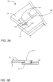
FIG. 3A shows a portion of a roofing shingle, according to some embodiments.
FIG. 3B shows a sectional view of the roofing shingle of FIG. 3A, according to some embodiments.
FIG. 4 shows a punch for manufacturing the roofing shingle of FIGS. 3A, 3B, according to some embodiments.
FIG. 5A shows a portion of a roofing shingle, according to some embodiments.
FIG. 5B shows a sectional view of the roofing shingle of FIG. 5A, according to some embodiments.
FIG. 6 shows a punch for manufacturing the roofing shingle of FIGS. 5A, 5B, according to some embodiments.
FIG. 7A shows a portion of a roofing shingle, according to some embodiments.
FIG. 7B shows a sectional view of the roofing shingle of FIG. 7A, according to some embodiments.
FIG. 8 shows a punch for manufacturing the roofing shingle of FIGS. 7A, 7B, according to some embodiments.
FIG. 9 shows a wheel used to manufacture a roofing shingle, according to some embodiments.
Like reference numbers represent the same or similar parts throughout.
DETAILED DESCRIPTION
An article, such as a multilayered roofing shingle, can be formed of multiple layers fastened together using a series of indentations. When handled (e.g., during transport/delivery or the like), such multilayered roofing shingles can develop small, benign cracks at an edge of a layer where the layer is fastened to another layer.
Embodiments of this disclosure can reduce stresses around an indentation fastening the two layers together. In some embodiments, the layers can be fastened by an indentation punch in which one layer of the shingle is partially pressed into the other layer. In some embodiments, the indentations are made on the back side of the laminated shingle such that the back layer is partially indented into the front layer. In some embodiments, the indentations are made in an area where laminating adhesive is applied in the common bond area. In such embodiments, the indentations can be made after application of the laminating adhesive.
Embodiments of this disclosure further include an elongated and tapered punch (e.g., toward the edge of the back layer (e.g., the backer layer)), which creates an indentation that tapers out to the edge of the back layer and reduces or eliminates the edge stress of a single round punch. The indentations extend to the edge of the back layer. In some embodiments, the punch can be barrel-shaped, flattened teardrop shaped, rounded taper teardrop shaped, or combinations thereof. The punches provide a more visible punch and a stress relieving function toward the edge of the back layer.
FIG. 1A shows a front view of an article 10, according to some embodiments. FIG. 1B shows a rear view of the article 10 in FIG. 1A, according to some embodiments. FIG. 1C shows an exploded perspective view of the article 10 in FIGS. 1A, 1B, according to some embodiments.
Collectively, FIGS. 1A-1C show the article 10, according to some embodiments. In some embodiments, the article 10 is a roofing shingle. In some embodiments, the article 10 is a multilayered roofing shingle. The illustrated article 10 is a two-layered roofing shingle. It is to be appreciated that the article 10 can be a multilayered roofing shingle that includes more than two layers.
Referring to FIG. 1A, the article 10 includes a first layer 15 and a second layer 20. The first layer 15 can be referred to as the top layer 15 and the second layer 20 can be referred to as the bottom layer 20. In some embodiments, the first layer 15 can be a dragon tooth layer. In some embodiments, the second layer 20 can be a backer layer.
The article 10 can include a fines stripe 25, a paint line, or combination thereof, on the first layer 15. In some embodiments, the fines stripe 25 can mark an area of the article 10 which an installer (e.g., a roofer or the like) nails the article 10 to a roof of a building when installing.
Referring to FIG. 1B, the article 10 includes a plurality of indentations 30. The plurality of indentations 30 are spaced from one another and extend along a major dimension L of the article 10. In some embodiments, the plurality of indentations 30 extend along the entire major dimension L of the article 10. In some embodiments, the plurality of indentations 30 can be aligned such that a feature (e.g., an extent of the plurality of indentations 30, a center of the plurality of indentations 30, or the like) is colinear along the major dimension L. A number and spacing S of the plurality of indentations 30 can vary. In some embodiments, the spacing S can be from at or about 0.1 inches to at or about 5 inches. In some embodiments, the spacing S can be from at or about 0.25 inches to at or about 2.5 inches. In some embodiments, the spacing S can be from at or about 0.5 inches to at or about 2 inches. In some embodiments, the spacing S can be at or about 1 inches.
The indentations 30 are shown in FIG. 1C. However, it is to be appreciated that this is for illustrative purposes only and that the indentations 30 are present when the first layer 15 and the second layer 20 are joined together. Moreover, the indentations 30 would also be formed into the first layer 15, though not visible in FIG. 1C for simplicity of the figures. Examples are shown and described relative to FIGS. 3A-8 below.
The plurality of indentations 30 can be oriented such that a major dimension X of the indentations is parallel to a minor dimension W of the article 10. In some embodiments, the major dimension X can be from at or about 0.1 inches to at or about 1 inch.
The plurality of indentations 30 can have a minor dimension Y. In some embodiments, the minor dimension Y can be from at or about 0.05 inches to at or about 0.15 inches.
The plurality of indentations 30 can partially press the second layer 20 into the first layer 15 such that the second layer 20 is partially indented into the first layer 15. This is shown and described in additional detail in accordance with FIGS. 3A-8 below. The plurality of indentations 30 do not pierce through the front surface of the first layer 15.
The plurality of indentations 30 can have a barrel shape (FIGS. 3A, 3B below), a flattened teardrop shape (FIGS. 5A, 5B below), a rounded taper teardrop shape (FIGS. 7A, 7B below), or combinations thereof. In some embodiments, the plurality of indentations 30 are the same shape. In some embodiments, the plurality of indentations 30 can have different shapes. Generally, it may be simpler to manufacture the article 10 when the plurality of indentations 30 are the same along the major dimension L of the article 10.
The plurality of indentations 30 can secure the second layer 20 to the first layer 15. That is, in some embodiments, the plurality of indentations 30 can secure the second layer 20 to the first layer 15 without additional securements such as, but not limited to, adhesives or fasteners. In some embodiments, the article 10 can include a layer of an adhesive 35 (FIG. 1C) applied between the first layer 15 and the second layer 20. In such embodiments, the first layer 15 and the second layer 20 can be held together by a combination including the plurality of indentations 30 and the adhesive 35.
In some embodiments, the plurality of indentations 30 can have a depth of at or about 0.05 to at or about 0.2 inches. In some embodiments, the plurality of indentations 30 can have a depth of at or about 0.1 inches. As used herein, “at or about” can be subject to, for example, manufacturing tolerances or the like. In some embodiments, the plurality of indentations 30 are flattened teardrop shaped and have a depth of at or about 0.1 inches. In some embodiments, the plurality of indentations 30 are rounded taper teardrop shaped and have a depth of at or about 0.1 inches.
A portion of the first layer 15 overlaps the second layer 20. The portion can be referred to as the common bond area 40. In some embodiments, the plurality of indentations 30 are formed within the common bond area 40. Similarly, when an adhesive is present, the adhesive is included in the common bond area 40 between the first layer 15 and the second layer 20.
FIG. 2 shows a flowchart for a method 100, according to some embodiments. The method 100 can generally be performed to manufacture an article such as the article 10 (FIGS. 1A-1C). In some embodiments, the method 100 is performed to secure layers of a roofing shingle together to form a multilayer roofing shingle. In some embodiments, the method 100 can be used to manufacture the roofing shingles shown and described in accordance with FIGS. 3A, 3B, 5A, 5B, 7A, and 7B below.
At block 105, the method 100 includes aligning a first layer (e.g., the first layer 15 of FIGS. 1A-1C) of an article (e.g., the article 10 of FIGS. 1A-1C) with a second layer (e.g., the second layer 20 of FIGS. 1A-1C) of the article. The first layer includes a front surface and a back surface. The second layer includes a front surface and a back surface. The front surface of the second layer contacts the back surface of the first layer when aligned. In some embodiments, an adhesive layer can be disposed between the front surface of the second layer and the back surface of the first layer.
At block 110, the method 100 includes indenting the second layer into the first layer sufficiently to fasten the second layer to the first layer. The indenting includes forming a plurality of indentations that are at least one of barrel-shaped, flattened teardrop shaped, rounded taper teardrop shaped, or combinations thereof. In some embodiments, the method 100 includes indenting the second layer into the first layer along an entire major dimension (e.g., major dimension L in FIGS. 1A, 1B) of the article. In some embodiments, block 110 includes rolling a wheel (e.g., the wheel 450 of FIG. 9 ) across a the major dimension of the article.
In some embodiments, an adhesive can optionally be applied prior to block 110. In such embodiments, the adhesive can be applied prior to block 105 (e.g., at block 115) in some embodiments. When the adhesive is present, the adhesive can be applied to the front surface of the second layer or to the back surface of the first layer.
In some embodiments, a fines stripe can be applied at block 120 onto a front surface of the first layer.
FIG. 3A shows a roofing shingle 150, according to some embodiments. FIG. 3B shows a sectional view of the roofing shingle 150, according to some embodiments. FIGS. 3A-3B will be discussed generally, unless specific reference is made otherwise.
The roofing shingle 150 includes a plurality of barrel-shaped indentations 155. The plurality of barrel-shaped indentations 155 are spaced along the major dimension L of the roofing shingle 150. The roofing shingle 150 includes the first layer 15 and the second layer 20. The plurality of barrel-shaped indentations 155 have a length 160 and a width 165. A depth 170 is such that a portion of the second layer 20 is indented into the first layer 15, without piercing through the first layer 15. In the illustrated embodiment, the plurality of barrel-shaped indentations 155 are adjacent to an edge 180 of the second layer 20.
FIG. 4 shows a punch 200 for manufacturing the roofing shingle 150 of FIGS. 3A, 3B, according to some embodiments. The punch 200 has a rounded-barrel shape. The punch has a length 205 and a width 210. The length 205 corresponds to the length 160 (FIG. 3A) and the width 210 to the width 165 (FIG. 3A) of the plurality of barrel-shaped indentations 155 (FIG. 3A). A height 215 of the punch 200 corresponds to the depth 170 (FIG. 3B).
FIG. 5A shows a roofing shingle 250, according to some embodiments. FIG. 5B shows a sectional view of the roofing shingle 250, according to some embodiments. FIGS. 5A-5B will be discussed generally, unless specific reference is made otherwise.
The roofing shingle 250 includes a plurality of flattened teardrop shaped indentations 255. The plurality of flattened teardrop shaped indentations 255 are spaced along the major dimension L of the roofing shingle 250. The roofing shingle 250 includes the first layer 15 and the second layer 20. The plurality of flattened teardrop shaped indentations 255 have a length 260 and a width 265. A depth 270 is such that a portion of the second layer 20 is indented into the first layer 15, without piercing through the first layer 15. The depth 270 is shallower at an edge 280 of the second layer 20 than spaced from the edge 280. That is, the depth 270 varies due to the flattened teardrop shape. In the illustrated embodiment, the plurality of flattened teardrop shaped indentations 255 are adjacent to the edge 280 of the second layer 20.
FIG. 6 shows a punch 300 for manufacturing the roofing shingle 250 of FIGS. 5A, 5B, according to some embodiments. The punch 300 has a flattened teardrop shape. The punch has a length 305 and a width 310. The length 305 corresponds to the length 260 (FIG. 5A) and the width 310 to the width 265 (FIG. 5A) of the plurality of flattened teardrop shaped indentations 255 (FIG. 5A). A height 315 of the punch 300 corresponds to the depth 270 (FIG. 5B). The punch 300 has a radius 320. In some embodiments, the radius 320 is at or about 0.06 inches.
FIG. 7A shows a roofing shingle 350, according to some embodiments. FIG. 7B shows a sectional view of the roofing shingle 350, according to some embodiments. FIGS. 7A-7B will be discussed generally, unless specific reference is made otherwise.
The roofing shingle 350 includes a plurality of rounded taper teardrop shaped indentations 355. The plurality of rounded taper teardrop shaped indentations 355 are spaced along the major dimension L of the roofing shingle 350. The roofing shingle 350 includes the first layer 15 and the second layer 20. The plurality of rounded taper teardrop shaped indentations 355 have a length 360 and a width 365. As shown, the width 365 tapers toward an edge 380 such that the width is relatively smallest adjacent the edge 380 (i.e., narrower at the edge 380). A depth 370 is such that a portion of the second layer 20 is indented into the first layer 15, without piercing through the first layer 15. The depth 370 is shallower at the edge 380 of the second layer 20 than spaced from the edge 380. That is, the depth 370 varies due to the rounded taper teardrop shape. In the illustrated embodiment, the plurality of rounded taper teardrop shaped indentations 355 are formed adjacent to the edge 380 (i.e., not spaced).
FIG. 8 shows a punch 400 for manufacturing the roofing shingle 350 of FIGS. 7A, 7B, according to some embodiments. The punch 400 has a rounded taper teardrop shape. The punch has a length 405 and a width 410. The length 405 corresponds to the length 360 (FIG. 7A) and the width 410 to the width 365 (FIG. 7A) of the plurality of rounded taper teardrop shaped indentations 355 (FIG. 7A). A height 415 of the punch 400 corresponds to the depth 370 (FIG. 7B). The punch 400 has a radius 420. In some embodiments, the radius is at or about 0.04 inches.
FIG. 9 shows a wheel 450 used to manufacture an article such as the article 10 (FIGS. 1A-1C) or the roofing shingles 150, 250, 350 (FIGS. 3A, 3B, 5A, 5B, 7A, 7B), according to some embodiments. In the illustrated embodiment, the wheel 450 include a plurality of punches 200. It is to be appreciated that the punches 200 are an example. In some embodiments, the punches 200 on the wheel 450 can be replaced by the punch 300 or the punch 400. In some embodiments, the wheel 450 can include a combination of punches 200, 300, or 400.
In some embodiments, the punches 200 can be spaced 455 at or about 1 inch apart. In some embodiments, the punches 200 can be spaced from at or about 0.5 inches to at or about 2 inches apart. It is to be appreciated that the spacing between the punches 200 can vary according to a spacing of indentations on the article.
The terminology used herein is intended to describe embodiments and is not intended to be limiting. The terms “a,” “an,” and “the” include the plural forms as well, unless clearly indicated otherwise. The terms “comprises” and/or “comprising,” when used in this Specification, specify the presence of the stated features, integers, steps, operations, elements, and/or components, but do not preclude the presence or addition of one or more other features, integers, steps, operations, elements, and/or components.
It is to be understood that changes may be made in detail, especially in matters of the construction materials employed and the shape, size, and arrangement of parts without departing from the scope of the present disclosure. This Specification and the embodiments described are examples, with the true scope and spirit of the disclosure being indicated by the embodiments that follow.

Claims (13)

What is claimed is:
1. A roofing shingle, comprising:
a first layer including a front surface and a back surface;
a second layer including a front surface and a back surface,
wherein a portion of the second layer overlaps the first layer,
wherein a portion of the second layer fastened to the first layer,
wherein the back surface of the first layer contacts the front surface of the second layer; and
a plurality of indentations spaced apart along a major dimension of the roofing shingle, wherein the plurality of indentations partially presses the second layer into the first layer such that the second layer is partially indented into the first layer, and
wherein the plurality of indentations extends to an edge of the second layer which extends along the major dimension of the roofing shingle.
2. The roofing shingle of claim 1, wherein the first layer is a dragon tooth layer and the second layer is a backer layer.
3. The roofing shingle of claim 1, comprising an adhesive between the first layer and the second layer.
4. The roofing shingle of claim 1, wherein the plurality of indentations have a depth of 0.05 to 0.2 inches.
5. The roofing shingle of claim 1, wherein the plurality of indentations comprise a flattened teardrop shape and have a depth of 0.1 inches.
6. The roofing shingle of claim 1, wherein the plurality of indentations comprise a rounded taper teardrop shape and have a depth of 0.1 inches.
7. The roofing shingle of claim 1, wherein the first layer comprises a fines stripe disposed on the front surface of the first layer.
8. The roofing shingle of claim 1, wherein the plurality of indentations aligned along the major dimension of the roofing shingle.
9. The roofing shingle of claim 1, wherein the plurality of indentations taper such that the plurality of indentations are narrower at an edge of the second layer.
10. The roofing shingle of claim 1, wherein the plurality of indentations extend along an entire length of an area where the first layer overlaps the second layer.
11. The roofing shingle of claim 1, wherein the plurality of indentations comprises a cylindrical shape.
12. The roofing shingle of claim 1, wherein the plurality of indentations comprise a flattened teardrop shape.
13. The roofing shingle of claim 1, wherein the plurality of indentations comprise a rounded taper teardrop shape.
US17/525,591 2020-11-13 2021-11-12 Roofing shingle and method of manufacturing thereof Active 2041-11-22 US11828065B2 (en)

Priority Applications (2)

Application Number Priority Date Filing Date Title
US17/525,591 US11828065B2 (en) 2020-11-13 2021-11-12 Roofing shingle and method of manufacturing thereof
US18/361,327 US20240026684A1 (en) 2020-11-13 2023-07-28 Roofing shingle and method of manufacturing thereof

Applications Claiming Priority (2)

Application Number Priority Date Filing Date Title
US202063113618P 2020-11-13 2020-11-13
US17/525,591 US11828065B2 (en) 2020-11-13 2021-11-12 Roofing shingle and method of manufacturing thereof

Related Child Applications (1)

Application Number Title Priority Date Filing Date
US18/361,327 Continuation US20240026684A1 (en) 2020-11-13 2023-07-28 Roofing shingle and method of manufacturing thereof

Publications (2)

Publication Number Publication Date
US20220154469A1 US20220154469A1 (en) 2022-05-19
US11828065B2 true US11828065B2 (en) 2023-11-28

Family

ID=81586527

Family Applications (2)

Application Number Title Priority Date Filing Date
US17/525,591 Active 2041-11-22 US11828065B2 (en) 2020-11-13 2021-11-12 Roofing shingle and method of manufacturing thereof
US18/361,327 Pending US20240026684A1 (en) 2020-11-13 2023-07-28 Roofing shingle and method of manufacturing thereof

Family Applications After (1)

Application Number Title Priority Date Filing Date
US18/361,327 Pending US20240026684A1 (en) 2020-11-13 2023-07-28 Roofing shingle and method of manufacturing thereof

Country Status (4)

Country Link
US (2) US11828065B2 (en)
CA (1) CA3197593A1 (en)
MX (1) MX2023005597A (en)
WO (1) WO2022104111A1 (en)

Citations (41)

* Cited by examiner, † Cited by third party
Publication number Priority date Publication date Assignee Title
US1765796A (en) 1926-04-10 1930-06-24 Patent & Licensing Corp Sealed laminated roofing element
US1998590A (en) 1932-01-11 1935-04-23 Woodall Industries Inc Method of constructing door panels
US2232786A (en) 1939-08-28 1941-02-25 Creo Dipt Company Inc Shingle structure
US3197355A (en) 1961-04-20 1965-07-27 Sackner Prod Inc Method of making a pattern coated backing and product
US3256131A (en) 1962-12-05 1966-06-14 Fibremetal Inc Embossed laminate and method of making same
US4102107A (en) 1970-06-22 1978-07-25 Shakertown Corporation Prefabricated shingle panels
US4148168A (en) 1977-12-08 1979-04-10 Diamond John N Jig assembly and method for the manufacture of prefabricated roofing panels
US4466226A (en) 1982-11-18 1984-08-21 Rohner Nicholas J Methods of applying roofing shingles
US4671037A (en) 1986-06-11 1987-06-09 Joseph Bienvenu Roof construction
US4798754A (en) 1987-08-10 1989-01-17 Tomek Lawrence S Oil-absorbent floor mat
US5232530A (en) 1987-12-04 1993-08-03 Elk Corporation Of Dallas Method of making a thick shingle
US5305569A (en) 1989-04-19 1994-04-26 Elk Corporation Of Dallas Thick shingle
US5421134A (en) 1990-04-27 1995-06-06 Certainteed Corporation Roofing shingle
US5666776A (en) 1991-09-18 1997-09-16 Elk Corporation Of Dallas Laminated roofing shingle
US5671577A (en) 1995-06-06 1997-09-30 Masco Corporation Roofing shingle
US5822943A (en) 1996-07-10 1998-10-20 Tamko Roofing Products, Inc. Hurricane resistant shingle
US5950387A (en) 1998-05-11 1999-09-14 Certainteed Corporation Wind-resistant shingle and method of applying
US5956913A (en) 1995-04-13 1999-09-28 Nicholson; Joseph R. Shingle system and fastening strip
US6014847A (en) 1998-08-31 2000-01-18 Owens Corning Fiberglas Technology, Inc. Laminated roofing shingle having staggered shadow lines and method of making the same
US6083592A (en) 1998-09-03 2000-07-04 Building Materials Corporation Of America Self-sealing shingle adhesive load relief
US6145265A (en) 1999-02-17 2000-11-14 Herbert Malarkey Roofing Company Laminated shingle
US6289648B1 (en) 1999-09-22 2001-09-18 Elk Corporation Of Dallas Laminated roofing shingle
KR20020048786A (en) 2000-12-18 2002-06-24 마이클 디. 오브라이언 Structure of double -sided adhesive tape for bonding die of Semiconductor Package
US6471812B1 (en) 1999-09-03 2002-10-29 Owens Corning Fiberglas Technology, Inc. Reducing humping of roofing shingles
US6470642B1 (en) 2000-08-02 2002-10-29 Perry Lewis Eads Self-sealing roof shingle mounting system and attachment apparatus, and method of using same
US6510664B2 (en) 2001-06-14 2003-01-28 Stephen J. Kupczyk Multi-layered shingle
US6679020B2 (en) 1999-05-03 2004-01-20 Certainteed Corporation Multi-layered shingle and method of making same
US20040079042A1 (en) 2002-10-29 2004-04-29 Elliott Bert W. Multi-layer laminated shingle
US20040206035A1 (en) 2003-04-17 2004-10-21 Emco Building Products Limited Roofing shingle with headlap seal and improved coverage
US20040258883A1 (en) 2003-06-17 2004-12-23 Elkcorp. Laminated roofing shingle
US6968662B2 (en) 2002-12-04 2005-11-29 Building Materials Investment Corporaion Sealing courses of shingles
US7836654B2 (en) 2005-08-05 2010-11-23 Owens Corning Intellectual Capital, Llc Shingle with reinforced nail zone and method of manufacturing
US8006457B2 (en) * 2004-06-07 2011-08-30 Building Materials Investment Corporation Enhanced multi-layered shingle
US20120047838A1 (en) 2002-11-06 2012-03-01 Certainteed Corporation Shingle With Reinforcement Layer
US8297020B1 (en) 2007-12-20 2012-10-30 Top Down Siding LLC Top down trap lock two-ply shingle system for roofs
US20130025225A1 (en) 2011-07-29 2013-01-31 Owens Corning Intellectual Capital, Llc Method of sealing overlapping installed shingles
US8535786B2 (en) 2006-08-18 2013-09-17 Ewald Dorken Ag Web and adhesive strip
US8607521B2 (en) 2005-08-05 2013-12-17 Owens Corning Intellectual Capital, Llc Shingle with reinforced nail zone and method of manufacturing
US8623164B2 (en) 2005-08-05 2014-01-07 Owens Corning Intellectual Capital, Llc Shingle with reinforced nail zone and method of manufacturing
US20140260078A1 (en) * 2013-03-14 2014-09-18 Building Materials Investment Corporation Light weight shingle
US20200040582A1 (en) 2018-08-06 2020-02-06 Building Materials Investment Corporation Roofing Shingle System and Shingles For Use Therein

Family Cites Families (4)

* Cited by examiner, † Cited by third party
Publication number Priority date Publication date Assignee Title
US6421976B1 (en) * 1999-10-29 2002-07-23 Owens Corning Fiberglas Technology, Inc. Shingle for optically simulating a tile roof
US20060265989A1 (en) * 2005-05-24 2006-11-30 Geary David A Self-Aligning Roofing Shingles
US9103124B2 (en) * 2010-12-20 2015-08-11 Laurie Anne Spencer Shingle inserts and method for eliminating and preventing growth of algae, moss, or lichens on a roof
US10577800B2 (en) * 2015-02-19 2020-03-03 Roofers Advantage Products, LLC Layout starter and field shingle for sloped asphalt roofing

Patent Citations (48)

* Cited by examiner, † Cited by third party
Publication number Priority date Publication date Assignee Title
US1765796A (en) 1926-04-10 1930-06-24 Patent & Licensing Corp Sealed laminated roofing element
US1998590A (en) 1932-01-11 1935-04-23 Woodall Industries Inc Method of constructing door panels
US2232786A (en) 1939-08-28 1941-02-25 Creo Dipt Company Inc Shingle structure
US3197355A (en) 1961-04-20 1965-07-27 Sackner Prod Inc Method of making a pattern coated backing and product
US3256131A (en) 1962-12-05 1966-06-14 Fibremetal Inc Embossed laminate and method of making same
US4102107A (en) 1970-06-22 1978-07-25 Shakertown Corporation Prefabricated shingle panels
US4148168A (en) 1977-12-08 1979-04-10 Diamond John N Jig assembly and method for the manufacture of prefabricated roofing panels
US4466226A (en) 1982-11-18 1984-08-21 Rohner Nicholas J Methods of applying roofing shingles
US4671037A (en) 1986-06-11 1987-06-09 Joseph Bienvenu Roof construction
US4798754A (en) 1987-08-10 1989-01-17 Tomek Lawrence S Oil-absorbent floor mat
US5232530A (en) 1987-12-04 1993-08-03 Elk Corporation Of Dallas Method of making a thick shingle
US5305569A (en) 1989-04-19 1994-04-26 Elk Corporation Of Dallas Thick shingle
US5421134A (en) 1990-04-27 1995-06-06 Certainteed Corporation Roofing shingle
US5666776A (en) 1991-09-18 1997-09-16 Elk Corporation Of Dallas Laminated roofing shingle
US5956913A (en) 1995-04-13 1999-09-28 Nicholson; Joseph R. Shingle system and fastening strip
US5671577A (en) 1995-06-06 1997-09-30 Masco Corporation Roofing shingle
US5822943A (en) 1996-07-10 1998-10-20 Tamko Roofing Products, Inc. Hurricane resistant shingle
US5950387A (en) 1998-05-11 1999-09-14 Certainteed Corporation Wind-resistant shingle and method of applying
US6014847A (en) 1998-08-31 2000-01-18 Owens Corning Fiberglas Technology, Inc. Laminated roofing shingle having staggered shadow lines and method of making the same
US6083592A (en) 1998-09-03 2000-07-04 Building Materials Corporation Of America Self-sealing shingle adhesive load relief
US6145265A (en) 1999-02-17 2000-11-14 Herbert Malarkey Roofing Company Laminated shingle
US6397546B1 (en) 1999-02-17 2002-06-04 Herbert Malarkey Roofing Co. Laminated shingle
US6679020B2 (en) 1999-05-03 2004-01-20 Certainteed Corporation Multi-layered shingle and method of making same
US6471812B1 (en) 1999-09-03 2002-10-29 Owens Corning Fiberglas Technology, Inc. Reducing humping of roofing shingles
US6289648B1 (en) 1999-09-22 2001-09-18 Elk Corporation Of Dallas Laminated roofing shingle
US6470642B1 (en) 2000-08-02 2002-10-29 Perry Lewis Eads Self-sealing roof shingle mounting system and attachment apparatus, and method of using same
KR20020048786A (en) 2000-12-18 2002-06-24 마이클 디. 오브라이언 Structure of double -sided adhesive tape for bonding die of Semiconductor Package
US6510664B2 (en) 2001-06-14 2003-01-28 Stephen J. Kupczyk Multi-layered shingle
US20040079042A1 (en) 2002-10-29 2004-04-29 Elliott Bert W. Multi-layer laminated shingle
US20120047838A1 (en) 2002-11-06 2012-03-01 Certainteed Corporation Shingle With Reinforcement Layer
US6968662B2 (en) 2002-12-04 2005-11-29 Building Materials Investment Corporaion Sealing courses of shingles
US20040206035A1 (en) 2003-04-17 2004-10-21 Emco Building Products Limited Roofing shingle with headlap seal and improved coverage
US20040258883A1 (en) 2003-06-17 2004-12-23 Elkcorp. Laminated roofing shingle
US8127514B2 (en) 2004-06-07 2012-03-06 Elk Premium Building Products, Inc. Enhanced multi-layered shingle
US8006457B2 (en) * 2004-06-07 2011-08-30 Building Materials Investment Corporation Enhanced multi-layered shingle
US8156704B2 (en) 2005-08-05 2012-04-17 Owens-Corning Fiberglas Technology, Inc. Reducing humping of stacked roofing shingles
US7836654B2 (en) 2005-08-05 2010-11-23 Owens Corning Intellectual Capital, Llc Shingle with reinforced nail zone and method of manufacturing
US8181413B2 (en) 2005-08-05 2012-05-22 Owens Corning Intellectual Capital, Llc Shingle with reinforced nail zone and method of manufacturing
US8240102B2 (en) 2005-08-05 2012-08-14 Owens Corning Intellectual Capital, Llc Shingle with reinforced nail zone and method of manufacturing
US8607521B2 (en) 2005-08-05 2013-12-17 Owens Corning Intellectual Capital, Llc Shingle with reinforced nail zone and method of manufacturing
US8623164B2 (en) 2005-08-05 2014-01-07 Owens Corning Intellectual Capital, Llc Shingle with reinforced nail zone and method of manufacturing
US8752351B2 (en) 2005-08-05 2014-06-17 Owens Corning Intellectual Capital, Llc Shingle with reinforced nail zone and method of manufacturing
US8535786B2 (en) 2006-08-18 2013-09-17 Ewald Dorken Ag Web and adhesive strip
US8297020B1 (en) 2007-12-20 2012-10-30 Top Down Siding LLC Top down trap lock two-ply shingle system for roofs
US20130025225A1 (en) 2011-07-29 2013-01-31 Owens Corning Intellectual Capital, Llc Method of sealing overlapping installed shingles
US20140260078A1 (en) * 2013-03-14 2014-09-18 Building Materials Investment Corporation Light weight shingle
US20200040582A1 (en) 2018-08-06 2020-02-06 Building Materials Investment Corporation Roofing Shingle System and Shingles For Use Therein
US11352792B2 (en) * 2018-08-06 2022-06-07 Bmic Llc Roofing shingle system and shingles for use therein

Also Published As

Publication number Publication date
MX2023005597A (en) 2023-06-29
WO2022104111A1 (en) 2022-05-19
US20240026684A1 (en) 2024-01-25
CA3197593A1 (en) 2022-05-19
US20220154469A1 (en) 2022-05-19

Similar Documents

Publication Publication Date Title
CN105593011B (en) metal and graphite laminate
US6804919B2 (en) Backer for tabbed composite shingles
US3950910A (en) Shelter panel
CA2509294A1 (en) Enhanced multi-layered shingle
ES2186184T3 (en) PROCEDURE TO PERFORM A ROLLING AND ROLLING OBTAINED BY MEANS OF THIS PROCEDURE.
TW201522059A (en) Joining of textured sheet materials
US5380579A (en) Honeycomb panel with interlocking core strips
US11828065B2 (en) Roofing shingle and method of manufacturing thereof
JP6479922B1 (en) Roof repair method and roof structure
US10801535B2 (en) Self-piercing fastener
EP2924186B1 (en) Building connection with nail plate hanger with bendable tab
CN106881915A (en) A kind of composite metal plate and preparation method thereof
US6299400B1 (en) Deck fastener, method of driving and method of manufacture of fastener
US9758969B2 (en) Roofing system
US10208494B2 (en) Roof plug
US11549261B2 (en) Building material, stacked body of building materials, and building-material construction method
CN206663887U (en) A kind of composite metal plate
CN213674548U (en) Anti-collision plywood
CN213868717U (en) Floor block or wall panel
JP4558777B2 (en) Ceramic sheet stacking unit
JP4421452B2 (en) Attaching the waistline to the waistline and wall
WO2009085661A2 (en) Wire staple for attaching metal sheets
US20060225627A1 (en) Work surface, edge treatment and method for configuring work surface
JPH07266305A (en) Architectural plate and manufacture thereof
WO2013134058A1 (en) Bracing element

Legal Events

Date Code Title Description
FEPP Fee payment procedure

Free format text: ENTITY STATUS SET TO UNDISCOUNTED (ORIGINAL EVENT CODE: BIG.); ENTITY STATUS OF PATENT OWNER: LARGE ENTITY

STPP Information on status: patent application and granting procedure in general

Free format text: DOCKETED NEW CASE - READY FOR EXAMINATION

AS Assignment

Owner name: BMIC LLC, TEXAS

Free format text: ASSIGNMENT OF ASSIGNORS INTEREST;ASSIGNOR:SVEC, JAMES A.;REEL/FRAME:061980/0584

Effective date: 20221202

STPP Information on status: patent application and granting procedure in general

Free format text: RESPONSE TO NON-FINAL OFFICE ACTION ENTERED AND FORWARDED TO EXAMINER

STPP Information on status: patent application and granting procedure in general

Free format text: PUBLICATIONS -- ISSUE FEE PAYMENT RECEIVED

STPP Information on status: patent application and granting procedure in general

Free format text: PUBLICATIONS -- ISSUE FEE PAYMENT VERIFIED

STCF Information on status: patent grant

Free format text: PATENTED CASE