US11821075B2 - Anti-microbial coating physical vapor deposition such as cathodic arc evaporation - Google Patents
Anti-microbial coating physical vapor deposition such as cathodic arc evaporation Download PDFInfo
- Publication number
- US11821075B2 US11821075B2 US17/342,887 US202117342887A US11821075B2 US 11821075 B2 US11821075 B2 US 11821075B2 US 202117342887 A US202117342887 A US 202117342887A US 11821075 B2 US11821075 B2 US 11821075B2
- Authority
- US
- United States
- Prior art keywords
- bioactive
- layer
- coated substrate
- outermost
- copper
- Prior art date
- Legal status (The legal status is an assumption and is not a legal conclusion. Google has not performed a legal analysis and makes no representation as to the accuracy of the status listed.)
- Active, expires
Links
- 230000000845 anti-microbial effect Effects 0.000 title description 36
- 238000000576 coating method Methods 0.000 title description 15
- 238000005240 physical vapour deposition Methods 0.000 title description 13
- 239000011248 coating agent Substances 0.000 title description 9
- 239000004599 antimicrobial Substances 0.000 title description 5
- 230000008020 evaporation Effects 0.000 title description 4
- 238000001704 evaporation Methods 0.000 title description 4
- 230000000975 bioactive effect Effects 0.000 claims abstract description 230
- 239000000758 substrate Substances 0.000 claims abstract description 139
- 239000010410 layer Substances 0.000 claims description 273
- 239000010949 copper Substances 0.000 claims description 42
- RYGMFSIKBFXOCR-UHFFFAOYSA-N Copper Chemical compound [Cu] RYGMFSIKBFXOCR-UHFFFAOYSA-N 0.000 claims description 41
- 229910052802 copper Inorganic materials 0.000 claims description 38
- QCWXUUIWCKQGHC-UHFFFAOYSA-N Zirconium Chemical group [Zr] QCWXUUIWCKQGHC-UHFFFAOYSA-N 0.000 claims description 31
- 229910052726 zirconium Inorganic materials 0.000 claims description 29
- 229910052751 metal Inorganic materials 0.000 claims description 26
- 239000002184 metal Substances 0.000 claims description 26
- 239000011229 interlayer Substances 0.000 claims description 25
- 150000001875 compounds Chemical class 0.000 claims description 22
- 239000010936 titanium Chemical group 0.000 claims description 20
- RTAQQCXQSZGOHL-UHFFFAOYSA-N Titanium Chemical group [Ti] RTAQQCXQSZGOHL-UHFFFAOYSA-N 0.000 claims description 15
- 229910052719 titanium Chemical group 0.000 claims description 15
- 229910000881 Cu alloy Inorganic materials 0.000 claims description 13
- QPLDLSVMHZLSFG-UHFFFAOYSA-N Copper oxide Chemical class [Cu]=O QPLDLSVMHZLSFG-UHFFFAOYSA-N 0.000 claims description 12
- 229910016553 CuOx Inorganic materials 0.000 claims description 11
- OKTJSMMVPCPJKN-UHFFFAOYSA-N Carbon Chemical compound [C] OKTJSMMVPCPJKN-UHFFFAOYSA-N 0.000 claims description 8
- GWEVSGVZZGPLCZ-UHFFFAOYSA-N Titan oxide Chemical compound O=[Ti]=O GWEVSGVZZGPLCZ-UHFFFAOYSA-N 0.000 claims description 8
- BASFCYQUMIYNBI-UHFFFAOYSA-N platinum Chemical compound [Pt] BASFCYQUMIYNBI-UHFFFAOYSA-N 0.000 claims description 8
- NRTOMJZYCJJWKI-UHFFFAOYSA-N Titanium nitride Chemical compound [Ti]#N NRTOMJZYCJJWKI-UHFFFAOYSA-N 0.000 claims description 6
- -1 copper nitrides Chemical class 0.000 claims description 6
- 239000010931 gold Substances 0.000 claims description 6
- PCHJSUWPFVWCPO-UHFFFAOYSA-N gold Chemical compound [Au] PCHJSUWPFVWCPO-UHFFFAOYSA-N 0.000 claims description 5
- 229910052737 gold Inorganic materials 0.000 claims description 5
- 150000004767 nitrides Chemical class 0.000 claims description 5
- 229910010282 TiON Inorganic materials 0.000 claims description 4
- 229910006252 ZrON Inorganic materials 0.000 claims description 4
- 125000004432 carbon atom Chemical group C* 0.000 claims description 4
- 229910002804 graphite Inorganic materials 0.000 claims description 4
- 239000010439 graphite Substances 0.000 claims description 4
- 150000001247 metal acetylides Chemical class 0.000 claims description 4
- 230000003647 oxidation Effects 0.000 claims description 4
- 238000007254 oxidation reaction Methods 0.000 claims description 4
- 229910052697 platinum Inorganic materials 0.000 claims description 4
- MCMNRKCIXSYSNV-UHFFFAOYSA-N Zirconium dioxide Chemical compound O=[Zr]=O MCMNRKCIXSYSNV-UHFFFAOYSA-N 0.000 claims 6
- ATJFFYVFTNAWJD-UHFFFAOYSA-N Tin Chemical compound [Sn] ATJFFYVFTNAWJD-UHFFFAOYSA-N 0.000 claims 3
- 238000000034 method Methods 0.000 abstract description 17
- 239000000463 material Substances 0.000 description 27
- XKRFYHLGVUSROY-UHFFFAOYSA-N Argon Chemical compound [Ar] XKRFYHLGVUSROY-UHFFFAOYSA-N 0.000 description 18
- IJGRMHOSHXDMSA-UHFFFAOYSA-N Atomic nitrogen Chemical compound N#N IJGRMHOSHXDMSA-UHFFFAOYSA-N 0.000 description 15
- 238000005299 abrasion Methods 0.000 description 9
- 229910052786 argon Inorganic materials 0.000 description 9
- 230000008901 benefit Effects 0.000 description 9
- 239000000203 mixture Substances 0.000 description 9
- BQCADISMDOOEFD-UHFFFAOYSA-N Silver Chemical compound [Ag] BQCADISMDOOEFD-UHFFFAOYSA-N 0.000 description 7
- 238000006243 chemical reaction Methods 0.000 description 7
- 238000000151 deposition Methods 0.000 description 7
- 229910052709 silver Inorganic materials 0.000 description 7
- 239000004332 silver Substances 0.000 description 7
- 239000010935 stainless steel Substances 0.000 description 7
- 229910001220 stainless steel Inorganic materials 0.000 description 7
- PXHVJJICTQNCMI-UHFFFAOYSA-N Nickel Chemical compound [Ni] PXHVJJICTQNCMI-UHFFFAOYSA-N 0.000 description 6
- 229910052757 nitrogen Inorganic materials 0.000 description 6
- ZVWKZXLXHLZXLS-UHFFFAOYSA-N zirconium nitride Chemical compound [Zr]#N ZVWKZXLXHLZXLS-UHFFFAOYSA-N 0.000 description 6
- JPVYNHNXODAKFH-UHFFFAOYSA-N Cu2+ Chemical compound [Cu+2] JPVYNHNXODAKFH-UHFFFAOYSA-N 0.000 description 5
- QVGXLLKOCUKJST-UHFFFAOYSA-N atomic oxygen Chemical compound [O] QVGXLLKOCUKJST-UHFFFAOYSA-N 0.000 description 5
- 229910052799 carbon Inorganic materials 0.000 description 5
- 229910052760 oxygen Inorganic materials 0.000 description 5
- 239000001301 oxygen Substances 0.000 description 5
- 239000002243 precursor Substances 0.000 description 5
- 239000005751 Copper oxide Substances 0.000 description 4
- 239000003086 colorant Substances 0.000 description 4
- 238000010276 construction Methods 0.000 description 4
- 229910001431 copper ion Inorganic materials 0.000 description 4
- 229910000431 copper oxide Inorganic materials 0.000 description 4
- 238000001755 magnetron sputter deposition Methods 0.000 description 4
- 150000002739 metals Chemical class 0.000 description 4
- 239000002105 nanoparticle Substances 0.000 description 4
- 239000000126 substance Substances 0.000 description 4
- 229910001928 zirconium oxide Inorganic materials 0.000 description 4
- VYZAMTAEIAYCRO-UHFFFAOYSA-N Chromium Chemical compound [Cr] VYZAMTAEIAYCRO-UHFFFAOYSA-N 0.000 description 3
- 239000011651 chromium Substances 0.000 description 3
- XRBURMNBUVEAKD-UHFFFAOYSA-N chromium copper nickel Chemical compound [Cr].[Ni].[Cu] XRBURMNBUVEAKD-UHFFFAOYSA-N 0.000 description 3
- 239000011247 coating layer Substances 0.000 description 3
- 239000000470 constituent Substances 0.000 description 3
- 230000007547 defect Effects 0.000 description 3
- 230000008021 deposition Effects 0.000 description 3
- 229910001873 dinitrogen Inorganic materials 0.000 description 3
- 239000007789 gas Substances 0.000 description 3
- 230000036541 health Effects 0.000 description 3
- 229910001092 metal group alloy Inorganic materials 0.000 description 3
- 229910052759 nickel Inorganic materials 0.000 description 3
- XOFYZVNMUHMLCC-ZPOLXVRWSA-N prednisone Chemical compound O=C1C=C[C@]2(C)[C@H]3C(=O)C[C@](C)([C@@](CC4)(O)C(=O)CO)[C@@H]4[C@@H]3CCC2=C1 XOFYZVNMUHMLCC-ZPOLXVRWSA-N 0.000 description 3
- 238000004544 sputter deposition Methods 0.000 description 3
- 238000012360 testing method Methods 0.000 description 3
- 229910001369 Brass Inorganic materials 0.000 description 2
- WSFSSNUMVMOOMR-UHFFFAOYSA-N Formaldehyde Chemical compound O=C WSFSSNUMVMOOMR-UHFFFAOYSA-N 0.000 description 2
- XEEYBQQBJWHFJM-UHFFFAOYSA-N Iron Chemical compound [Fe] XEEYBQQBJWHFJM-UHFFFAOYSA-N 0.000 description 2
- 239000010951 brass Substances 0.000 description 2
- 229910052804 chromium Inorganic materials 0.000 description 2
- 230000001332 colony forming effect Effects 0.000 description 2
- 230000001010 compromised effect Effects 0.000 description 2
- 201000010099 disease Diseases 0.000 description 2
- 208000037265 diseases, disorders, signs and symptoms Diseases 0.000 description 2
- 239000004744 fabric Substances 0.000 description 2
- 150000002500 ions Chemical class 0.000 description 2
- 239000011777 magnesium Substances 0.000 description 2
- 239000011159 matrix material Substances 0.000 description 2
- 229910044991 metal oxide Inorganic materials 0.000 description 2
- 150000004706 metal oxides Chemical class 0.000 description 2
- VNWKTOKETHGBQD-UHFFFAOYSA-N methane Chemical compound C VNWKTOKETHGBQD-UHFFFAOYSA-N 0.000 description 2
- 244000005700 microbiome Species 0.000 description 2
- 230000004048 modification Effects 0.000 description 2
- 238000012986 modification Methods 0.000 description 2
- RVTZCBVAJQQJTK-UHFFFAOYSA-N oxygen(2-);zirconium(4+) Chemical class [O-2].[O-2].[Zr+4] RVTZCBVAJQQJTK-UHFFFAOYSA-N 0.000 description 2
- 239000003973 paint Substances 0.000 description 2
- 238000002360 preparation method Methods 0.000 description 2
- NDVLTYZPCACLMA-UHFFFAOYSA-N silver oxide Chemical compound [O-2].[Ag+].[Ag+] NDVLTYZPCACLMA-UHFFFAOYSA-N 0.000 description 2
- 238000000427 thin-film deposition Methods 0.000 description 2
- 230000000007 visual effect Effects 0.000 description 2
- NSMXQKNUPPXBRG-SECBINFHSA-N (R)-lisofylline Chemical compound O=C1N(CCCC[C@H](O)C)C(=O)N(C)C2=C1N(C)C=N2 NSMXQKNUPPXBRG-SECBINFHSA-N 0.000 description 1
- 229910001316 Ag alloy Inorganic materials 0.000 description 1
- 229910000906 Bronze Inorganic materials 0.000 description 1
- 208000035473 Communicable disease Diseases 0.000 description 1
- VMQMZMRVKUZKQL-UHFFFAOYSA-N Cu+ Chemical compound [Cu+] VMQMZMRVKUZKQL-UHFFFAOYSA-N 0.000 description 1
- 241000588724 Escherichia coli Species 0.000 description 1
- GYHNNYVSQQEPJS-UHFFFAOYSA-N Gallium Chemical compound [Ga] GYHNNYVSQQEPJS-UHFFFAOYSA-N 0.000 description 1
- FYYHWMGAXLPEAU-UHFFFAOYSA-N Magnesium Chemical compound [Mg] FYYHWMGAXLPEAU-UHFFFAOYSA-N 0.000 description 1
- 241001272996 Polyphylla fullo Species 0.000 description 1
- 241000220317 Rosa Species 0.000 description 1
- HCHKCACWOHOZIP-UHFFFAOYSA-N Zinc Chemical compound [Zn] HCHKCACWOHOZIP-UHFFFAOYSA-N 0.000 description 1
- 229920000122 acrylonitrile butadiene styrene Polymers 0.000 description 1
- 229910045601 alloy Inorganic materials 0.000 description 1
- 239000000956 alloy Substances 0.000 description 1
- 229910052782 aluminium Inorganic materials 0.000 description 1
- XAGFODPZIPBFFR-UHFFFAOYSA-N aluminium Chemical compound [Al] XAGFODPZIPBFFR-UHFFFAOYSA-N 0.000 description 1
- 230000000844 anti-bacterial effect Effects 0.000 description 1
- 230000001580 bacterial effect Effects 0.000 description 1
- 244000052616 bacterial pathogen Species 0.000 description 1
- 230000009286 beneficial effect Effects 0.000 description 1
- 230000004071 biological effect Effects 0.000 description 1
- 230000008827 biological function Effects 0.000 description 1
- 230000015572 biosynthetic process Effects 0.000 description 1
- 239000010974 bronze Substances 0.000 description 1
- 239000003575 carbonaceous material Substances 0.000 description 1
- VNNRSPGTAMTISX-UHFFFAOYSA-N chromium nickel Chemical compound [Cr].[Ni] VNNRSPGTAMTISX-UHFFFAOYSA-N 0.000 description 1
- 210000001520 comb Anatomy 0.000 description 1
- 238000010411 cooking Methods 0.000 description 1
- KUNSUQLRTQLHQQ-UHFFFAOYSA-N copper tin Chemical compound [Cu].[Sn] KUNSUQLRTQLHQQ-UHFFFAOYSA-N 0.000 description 1
- 230000000249 desinfective effect Effects 0.000 description 1
- 230000001627 detrimental effect Effects 0.000 description 1
- 238000012377 drug delivery Methods 0.000 description 1
- 230000000694 effects Effects 0.000 description 1
- 230000002538 fungal effect Effects 0.000 description 1
- 229910052733 gallium Inorganic materials 0.000 description 1
- 238000010438 heat treatment Methods 0.000 description 1
- 230000036039 immunity Effects 0.000 description 1
- 239000004615 ingredient Substances 0.000 description 1
- 230000002401 inhibitory effect Effects 0.000 description 1
- 230000003993 interaction Effects 0.000 description 1
- 229910052742 iron Inorganic materials 0.000 description 1
- 229910052749 magnesium Inorganic materials 0.000 description 1
- 238000005259 measurement Methods 0.000 description 1
- 238000010297 mechanical methods and process Methods 0.000 description 1
- 230000005226 mechanical processes and functions Effects 0.000 description 1
- 150000002736 metal compounds Chemical class 0.000 description 1
- 238000012544 monitoring process Methods 0.000 description 1
- 239000002245 particle Substances 0.000 description 1
- 238000000554 physical therapy Methods 0.000 description 1
- 230000001766 physiological effect Effects 0.000 description 1
- 230000008288 physiological mechanism Effects 0.000 description 1
- 239000011148 porous material Substances 0.000 description 1
- 229910001923 silver oxide Inorganic materials 0.000 description 1
- 239000000344 soap Substances 0.000 description 1
- JBQYATWDVHIOAR-UHFFFAOYSA-N tellanylidenegermanium Chemical compound [Te]=[Ge] JBQYATWDVHIOAR-UHFFFAOYSA-N 0.000 description 1
- 239000010409 thin film Substances 0.000 description 1
- 238000011282 treatment Methods 0.000 description 1
- WFKWXMTUELFFGS-UHFFFAOYSA-N tungsten Chemical compound [W] WFKWXMTUELFFGS-UHFFFAOYSA-N 0.000 description 1
- 229910052721 tungsten Inorganic materials 0.000 description 1
- 239000010937 tungsten Substances 0.000 description 1
- 238000007740 vapor deposition Methods 0.000 description 1
- 238000009834 vaporization Methods 0.000 description 1
- 230000008016 vaporization Effects 0.000 description 1
- 230000003612 virological effect Effects 0.000 description 1
- XLYOFNOQVPJJNP-UHFFFAOYSA-N water Substances O XLYOFNOQVPJJNP-UHFFFAOYSA-N 0.000 description 1
- 239000011701 zinc Substances 0.000 description 1
- 229910052725 zinc Inorganic materials 0.000 description 1
Images


Classifications
-
- C—CHEMISTRY; METALLURGY
- C23—COATING METALLIC MATERIAL; COATING MATERIAL WITH METALLIC MATERIAL; CHEMICAL SURFACE TREATMENT; DIFFUSION TREATMENT OF METALLIC MATERIAL; COATING BY VACUUM EVAPORATION, BY SPUTTERING, BY ION IMPLANTATION OR BY CHEMICAL VAPOUR DEPOSITION, IN GENERAL; INHIBITING CORROSION OF METALLIC MATERIAL OR INCRUSTATION IN GENERAL
- C23C—COATING METALLIC MATERIAL; COATING MATERIAL WITH METALLIC MATERIAL; SURFACE TREATMENT OF METALLIC MATERIAL BY DIFFUSION INTO THE SURFACE, BY CHEMICAL CONVERSION OR SUBSTITUTION; COATING BY VACUUM EVAPORATION, BY SPUTTERING, BY ION IMPLANTATION OR BY CHEMICAL VAPOUR DEPOSITION, IN GENERAL
- C23C14/00—Coating by vacuum evaporation, by sputtering or by ion implantation of the coating forming material
- C23C14/22—Coating by vacuum evaporation, by sputtering or by ion implantation of the coating forming material characterised by the process of coating
- C23C14/24—Vacuum evaporation
- C23C14/32—Vacuum evaporation by explosion; by evaporation and subsequent ionisation of the vapours, e.g. ion-plating
- C23C14/325—Electric arc evaporation
-
- A—HUMAN NECESSITIES
- A01—AGRICULTURE; FORESTRY; ANIMAL HUSBANDRY; HUNTING; TRAPPING; FISHING
- A01N—PRESERVATION OF BODIES OF HUMANS OR ANIMALS OR PLANTS OR PARTS THEREOF; BIOCIDES, e.g. AS DISINFECTANTS, AS PESTICIDES OR AS HERBICIDES; PEST REPELLANTS OR ATTRACTANTS; PLANT GROWTH REGULATORS
- A01N59/00—Biocides, pest repellants or attractants, or plant growth regulators containing elements or inorganic compounds
- A01N59/16—Heavy metals; Compounds thereof
- A01N59/20—Copper
-
- A—HUMAN NECESSITIES
- A01—AGRICULTURE; FORESTRY; ANIMAL HUSBANDRY; HUNTING; TRAPPING; FISHING
- A01P—BIOCIDAL, PEST REPELLANT, PEST ATTRACTANT OR PLANT GROWTH REGULATORY ACTIVITY OF CHEMICAL COMPOUNDS OR PREPARATIONS
- A01P1/00—Disinfectants; Antimicrobial compounds or mixtures thereof
-
- C—CHEMISTRY; METALLURGY
- C23—COATING METALLIC MATERIAL; COATING MATERIAL WITH METALLIC MATERIAL; CHEMICAL SURFACE TREATMENT; DIFFUSION TREATMENT OF METALLIC MATERIAL; COATING BY VACUUM EVAPORATION, BY SPUTTERING, BY ION IMPLANTATION OR BY CHEMICAL VAPOUR DEPOSITION, IN GENERAL; INHIBITING CORROSION OF METALLIC MATERIAL OR INCRUSTATION IN GENERAL
- C23C—COATING METALLIC MATERIAL; COATING MATERIAL WITH METALLIC MATERIAL; SURFACE TREATMENT OF METALLIC MATERIAL BY DIFFUSION INTO THE SURFACE, BY CHEMICAL CONVERSION OR SUBSTITUTION; COATING BY VACUUM EVAPORATION, BY SPUTTERING, BY ION IMPLANTATION OR BY CHEMICAL VAPOUR DEPOSITION, IN GENERAL
- C23C14/00—Coating by vacuum evaporation, by sputtering or by ion implantation of the coating forming material
- C23C14/0015—Coating by vacuum evaporation, by sputtering or by ion implantation of the coating forming material characterized by the colour of the layer
-
- C—CHEMISTRY; METALLURGY
- C23—COATING METALLIC MATERIAL; COATING MATERIAL WITH METALLIC MATERIAL; CHEMICAL SURFACE TREATMENT; DIFFUSION TREATMENT OF METALLIC MATERIAL; COATING BY VACUUM EVAPORATION, BY SPUTTERING, BY ION IMPLANTATION OR BY CHEMICAL VAPOUR DEPOSITION, IN GENERAL; INHIBITING CORROSION OF METALLIC MATERIAL OR INCRUSTATION IN GENERAL
- C23C—COATING METALLIC MATERIAL; COATING MATERIAL WITH METALLIC MATERIAL; SURFACE TREATMENT OF METALLIC MATERIAL BY DIFFUSION INTO THE SURFACE, BY CHEMICAL CONVERSION OR SUBSTITUTION; COATING BY VACUUM EVAPORATION, BY SPUTTERING, BY ION IMPLANTATION OR BY CHEMICAL VAPOUR DEPOSITION, IN GENERAL
- C23C14/00—Coating by vacuum evaporation, by sputtering or by ion implantation of the coating forming material
- C23C14/02—Pretreatment of the material to be coated
- C23C14/024—Deposition of sublayers, e.g. to promote adhesion of the coating
- C23C14/025—Metallic sublayers
-
- C—CHEMISTRY; METALLURGY
- C23—COATING METALLIC MATERIAL; COATING MATERIAL WITH METALLIC MATERIAL; CHEMICAL SURFACE TREATMENT; DIFFUSION TREATMENT OF METALLIC MATERIAL; COATING BY VACUUM EVAPORATION, BY SPUTTERING, BY ION IMPLANTATION OR BY CHEMICAL VAPOUR DEPOSITION, IN GENERAL; INHIBITING CORROSION OF METALLIC MATERIAL OR INCRUSTATION IN GENERAL
- C23C—COATING METALLIC MATERIAL; COATING MATERIAL WITH METALLIC MATERIAL; SURFACE TREATMENT OF METALLIC MATERIAL BY DIFFUSION INTO THE SURFACE, BY CHEMICAL CONVERSION OR SUBSTITUTION; COATING BY VACUUM EVAPORATION, BY SPUTTERING, BY ION IMPLANTATION OR BY CHEMICAL VAPOUR DEPOSITION, IN GENERAL
- C23C14/00—Coating by vacuum evaporation, by sputtering or by ion implantation of the coating forming material
- C23C14/04—Coating on selected surface areas, e.g. using masks
-
- C—CHEMISTRY; METALLURGY
- C23—COATING METALLIC MATERIAL; COATING MATERIAL WITH METALLIC MATERIAL; CHEMICAL SURFACE TREATMENT; DIFFUSION TREATMENT OF METALLIC MATERIAL; COATING BY VACUUM EVAPORATION, BY SPUTTERING, BY ION IMPLANTATION OR BY CHEMICAL VAPOUR DEPOSITION, IN GENERAL; INHIBITING CORROSION OF METALLIC MATERIAL OR INCRUSTATION IN GENERAL
- C23C—COATING METALLIC MATERIAL; COATING MATERIAL WITH METALLIC MATERIAL; SURFACE TREATMENT OF METALLIC MATERIAL BY DIFFUSION INTO THE SURFACE, BY CHEMICAL CONVERSION OR SUBSTITUTION; COATING BY VACUUM EVAPORATION, BY SPUTTERING, BY ION IMPLANTATION OR BY CHEMICAL VAPOUR DEPOSITION, IN GENERAL
- C23C14/00—Coating by vacuum evaporation, by sputtering or by ion implantation of the coating forming material
- C23C14/06—Coating by vacuum evaporation, by sputtering or by ion implantation of the coating forming material characterised by the coating material
- C23C14/0641—Nitrides
-
- C—CHEMISTRY; METALLURGY
- C23—COATING METALLIC MATERIAL; COATING MATERIAL WITH METALLIC MATERIAL; CHEMICAL SURFACE TREATMENT; DIFFUSION TREATMENT OF METALLIC MATERIAL; COATING BY VACUUM EVAPORATION, BY SPUTTERING, BY ION IMPLANTATION OR BY CHEMICAL VAPOUR DEPOSITION, IN GENERAL; INHIBITING CORROSION OF METALLIC MATERIAL OR INCRUSTATION IN GENERAL
- C23C—COATING METALLIC MATERIAL; COATING MATERIAL WITH METALLIC MATERIAL; SURFACE TREATMENT OF METALLIC MATERIAL BY DIFFUSION INTO THE SURFACE, BY CHEMICAL CONVERSION OR SUBSTITUTION; COATING BY VACUUM EVAPORATION, BY SPUTTERING, BY ION IMPLANTATION OR BY CHEMICAL VAPOUR DEPOSITION, IN GENERAL
- C23C14/00—Coating by vacuum evaporation, by sputtering or by ion implantation of the coating forming material
- C23C14/06—Coating by vacuum evaporation, by sputtering or by ion implantation of the coating forming material characterised by the coating material
- C23C14/08—Oxides
- C23C14/083—Oxides of refractory metals or yttrium
-
- C—CHEMISTRY; METALLURGY
- C23—COATING METALLIC MATERIAL; COATING MATERIAL WITH METALLIC MATERIAL; CHEMICAL SURFACE TREATMENT; DIFFUSION TREATMENT OF METALLIC MATERIAL; COATING BY VACUUM EVAPORATION, BY SPUTTERING, BY ION IMPLANTATION OR BY CHEMICAL VAPOUR DEPOSITION, IN GENERAL; INHIBITING CORROSION OF METALLIC MATERIAL OR INCRUSTATION IN GENERAL
- C23C—COATING METALLIC MATERIAL; COATING MATERIAL WITH METALLIC MATERIAL; SURFACE TREATMENT OF METALLIC MATERIAL BY DIFFUSION INTO THE SURFACE, BY CHEMICAL CONVERSION OR SUBSTITUTION; COATING BY VACUUM EVAPORATION, BY SPUTTERING, BY ION IMPLANTATION OR BY CHEMICAL VAPOUR DEPOSITION, IN GENERAL
- C23C14/00—Coating by vacuum evaporation, by sputtering or by ion implantation of the coating forming material
- C23C14/06—Coating by vacuum evaporation, by sputtering or by ion implantation of the coating forming material characterised by the coating material
- C23C14/08—Oxides
- C23C14/085—Oxides of iron group metals
-
- C—CHEMISTRY; METALLURGY
- C23—COATING METALLIC MATERIAL; COATING MATERIAL WITH METALLIC MATERIAL; CHEMICAL SURFACE TREATMENT; DIFFUSION TREATMENT OF METALLIC MATERIAL; COATING BY VACUUM EVAPORATION, BY SPUTTERING, BY ION IMPLANTATION OR BY CHEMICAL VAPOUR DEPOSITION, IN GENERAL; INHIBITING CORROSION OF METALLIC MATERIAL OR INCRUSTATION IN GENERAL
- C23C—COATING METALLIC MATERIAL; COATING MATERIAL WITH METALLIC MATERIAL; SURFACE TREATMENT OF METALLIC MATERIAL BY DIFFUSION INTO THE SURFACE, BY CHEMICAL CONVERSION OR SUBSTITUTION; COATING BY VACUUM EVAPORATION, BY SPUTTERING, BY ION IMPLANTATION OR BY CHEMICAL VAPOUR DEPOSITION, IN GENERAL
- C23C14/00—Coating by vacuum evaporation, by sputtering or by ion implantation of the coating forming material
- C23C14/06—Coating by vacuum evaporation, by sputtering or by ion implantation of the coating forming material characterised by the coating material
- C23C14/08—Oxides
- C23C14/087—Oxides of copper or solid solutions thereof
-
- C—CHEMISTRY; METALLURGY
- C23—COATING METALLIC MATERIAL; COATING MATERIAL WITH METALLIC MATERIAL; CHEMICAL SURFACE TREATMENT; DIFFUSION TREATMENT OF METALLIC MATERIAL; COATING BY VACUUM EVAPORATION, BY SPUTTERING, BY ION IMPLANTATION OR BY CHEMICAL VAPOUR DEPOSITION, IN GENERAL; INHIBITING CORROSION OF METALLIC MATERIAL OR INCRUSTATION IN GENERAL
- C23C—COATING METALLIC MATERIAL; COATING MATERIAL WITH METALLIC MATERIAL; SURFACE TREATMENT OF METALLIC MATERIAL BY DIFFUSION INTO THE SURFACE, BY CHEMICAL CONVERSION OR SUBSTITUTION; COATING BY VACUUM EVAPORATION, BY SPUTTERING, BY ION IMPLANTATION OR BY CHEMICAL VAPOUR DEPOSITION, IN GENERAL
- C23C14/00—Coating by vacuum evaporation, by sputtering or by ion implantation of the coating forming material
- C23C14/22—Coating by vacuum evaporation, by sputtering or by ion implantation of the coating forming material characterised by the process of coating
- C23C14/34—Sputtering
- C23C14/35—Sputtering by application of a magnetic field, e.g. magnetron sputtering
-
- C—CHEMISTRY; METALLURGY
- C23—COATING METALLIC MATERIAL; COATING MATERIAL WITH METALLIC MATERIAL; CHEMICAL SURFACE TREATMENT; DIFFUSION TREATMENT OF METALLIC MATERIAL; COATING BY VACUUM EVAPORATION, BY SPUTTERING, BY ION IMPLANTATION OR BY CHEMICAL VAPOUR DEPOSITION, IN GENERAL; INHIBITING CORROSION OF METALLIC MATERIAL OR INCRUSTATION IN GENERAL
- C23C—COATING METALLIC MATERIAL; COATING MATERIAL WITH METALLIC MATERIAL; SURFACE TREATMENT OF METALLIC MATERIAL BY DIFFUSION INTO THE SURFACE, BY CHEMICAL CONVERSION OR SUBSTITUTION; COATING BY VACUUM EVAPORATION, BY SPUTTERING, BY ION IMPLANTATION OR BY CHEMICAL VAPOUR DEPOSITION, IN GENERAL
- C23C14/00—Coating by vacuum evaporation, by sputtering or by ion implantation of the coating forming material
- C23C14/58—After-treatment
- C23C14/5873—Removal of material
- C23C14/588—Removal of material by mechanical treatment
-
- C—CHEMISTRY; METALLURGY
- C23—COATING METALLIC MATERIAL; COATING MATERIAL WITH METALLIC MATERIAL; CHEMICAL SURFACE TREATMENT; DIFFUSION TREATMENT OF METALLIC MATERIAL; COATING BY VACUUM EVAPORATION, BY SPUTTERING, BY ION IMPLANTATION OR BY CHEMICAL VAPOUR DEPOSITION, IN GENERAL; INHIBITING CORROSION OF METALLIC MATERIAL OR INCRUSTATION IN GENERAL
- C23C—COATING METALLIC MATERIAL; COATING MATERIAL WITH METALLIC MATERIAL; SURFACE TREATMENT OF METALLIC MATERIAL BY DIFFUSION INTO THE SURFACE, BY CHEMICAL CONVERSION OR SUBSTITUTION; COATING BY VACUUM EVAPORATION, BY SPUTTERING, BY ION IMPLANTATION OR BY CHEMICAL VAPOUR DEPOSITION, IN GENERAL
- C23C28/00—Coating for obtaining at least two superposed coatings either by methods not provided for in a single one of groups C23C2/00 - C23C26/00 or by combinations of methods provided for in subclasses C23C and C25C or C25D
- C23C28/04—Coating for obtaining at least two superposed coatings either by methods not provided for in a single one of groups C23C2/00 - C23C26/00 or by combinations of methods provided for in subclasses C23C and C25C or C25D only coatings of inorganic non-metallic material
- C23C28/042—Coating for obtaining at least two superposed coatings either by methods not provided for in a single one of groups C23C2/00 - C23C26/00 or by combinations of methods provided for in subclasses C23C and C25C or C25D only coatings of inorganic non-metallic material including a refractory ceramic layer, e.g. refractory metal oxides, ZrO2, rare earth oxides
-
- C—CHEMISTRY; METALLURGY
- C23—COATING METALLIC MATERIAL; COATING MATERIAL WITH METALLIC MATERIAL; CHEMICAL SURFACE TREATMENT; DIFFUSION TREATMENT OF METALLIC MATERIAL; COATING BY VACUUM EVAPORATION, BY SPUTTERING, BY ION IMPLANTATION OR BY CHEMICAL VAPOUR DEPOSITION, IN GENERAL; INHIBITING CORROSION OF METALLIC MATERIAL OR INCRUSTATION IN GENERAL
- C23C—COATING METALLIC MATERIAL; COATING MATERIAL WITH METALLIC MATERIAL; SURFACE TREATMENT OF METALLIC MATERIAL BY DIFFUSION INTO THE SURFACE, BY CHEMICAL CONVERSION OR SUBSTITUTION; COATING BY VACUUM EVAPORATION, BY SPUTTERING, BY ION IMPLANTATION OR BY CHEMICAL VAPOUR DEPOSITION, IN GENERAL
- C23C28/00—Coating for obtaining at least two superposed coatings either by methods not provided for in a single one of groups C23C2/00 - C23C26/00 or by combinations of methods provided for in subclasses C23C and C25C or C25D
- C23C28/40—Coatings including alternating layers following a pattern, a periodic or defined repetition
- C23C28/42—Coatings including alternating layers following a pattern, a periodic or defined repetition characterized by the composition of the alternating layers
Definitions
- the present invention relates to a coating system with bioactive properties that is formed by physical vapor deposition and related methods.
- PVD Physical vapor deposition
- AAE cathodic arc evaporation
- Bioactive refers to a material having biological effects or physiological effects on living things.
- a bioactive material includes a material resulting in a modification in the normal biological function or a physiological mechanism of a living thing.
- Bioactive includes beneficial and detrimental effects to microorganisms or modifications to the normal functioning of a microorganism.
- One common bioactive material is antimicrobial substances.
- Antimicrobial coatings serve many purposes. Generally, antimicrobial coatings inhibit the growth or kill microbes like viral, bacterial or fungal organisms. One particularly relevant example includes preventing the spread of communicable diseases by the use of antimicrobial materials. Antimicrobial materials may also serve hygienic purposes.
- antimicrobial materials can be difficult and expensive. Further, antimicrobial properties may have other undesirable properties. For example, some antimicrobial materials may be too soft. Other antimicrobial materials may have poor abrasion resistance.
- Microban® is an antimicrobial coating that includes silver particles dispersed in an organic matrix. Antimicrobial coatings involving an organic matrix may have the aesthetic appearance of paint. In some applications, the appearance of paint may be undesirable.
- Some antimicrobial coatings may use nanoparticle vapor deposition to deposit nanoparticles with antimicrobial properties on the surface of a coating. For example, ABACO® from Protec, is an antimicrobial coating using nanoparticles. However, the use of nanoparticles can be complex and expensive. Further such coatings may have delicate surfaces or poor abrasion resistance.
- antimicrobial materials includes various metals.
- silver is known to have antimicrobial properties.
- silver can be expensive, and its properties may not be suitable for many applications.
- the appearance or abrasion resistance of silver may be unsuitable for certain applications.
- a bioactive coated substrate in at least one aspect, includes a base substrate, a first bioactive layer disposed over the base substrate, and a topcoat layer disposed on the outermost bioactive layer. Characteristically, the topcoat layer defines a plurality of pinholes that expose the outermost bioactive layer.
- a method of forming the bioactive coated substrate set forth herein includes steps of providing a base substrate and then depositing an outermost bioactive layer over the substrate.
- the outermost bioactive layer has a plurality of macroparticles extending from a surface of the outermost bioactive layer. Otherwise, macroparticles extending from the surface are applied to the outermost bioactive layer.
- a topcoat layer is deposited on the outermost bioactive layer. Characteristically, the plurality macroparticles extend into the topcoat layer. At least a portion of the plurality macroparticles is removed to form a plurality of pinholes in the topcoat layer down to the outermost bioactive layer.
- a bioactive coated substrate in still another aspect, includes a base substrate, an outermost bioactive layer disposed on the base substrate, and an indicator layer disposed below the outermost bioactive layer.
- FIG. 1 A is a cross-sectional view of a bioactive coated substrate having a plurality of pinholes in the topcoat layer.
- FIG. 1 B is a cross-sectional view of a bioactive coated substrate having multiple bioactive layers a plurality of pinholes in the topcoat layer
- FIG. 2 A is a side view of a cross-section of a bioactive coated substrate substantially pinhole-free and with a single bioactive layer and an indicator layer.
- FIG. 2 B is a side view of a cross-section of a bioactive coated substrate substantially pinhole-free and with multiple bioactive layers and an indicator layer
- FIG. 3 A is a cross-sectional view of a precursor coated substrate having a single bioactive layer with a plurality of macroparticles and a topcoat layer.
- FIG. 3 B is a cross-sectional view of a precursor coated substrate having multiple bioactive layers with an outermost bioactive layer having a plurality of macroparticles.
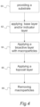
- FIG. 4 is a flow chart depicting a method for preparing a bioactive coated substrate.
- FIG. 5 provides Table 1 which shows properties of a bioactive coated substrates and a copper penny.
- percent, “parts of,” and ratio values are by weight; the description of a group or class of materials as suitable or preferred for a given purpose in connection with the invention implies that mixtures of any two or more of the members of the group or class are equally suitable or preferred; description of constituents in chemical terms refers to the constituents at the time of addition to any combination specified in the description, and does not necessarily preclude chemical interactions among the constituents of a mixture once mixed; the first definition of an acronym or other abbreviation applies to all subsequent uses herein of the same abbreviation and applies mutatis mutandis to normal grammatical variations of the initially defined abbreviation; and, unless expressly stated to the contrary, measurement of a property is determined by the same technique as previously or later referenced for the same property.
- substantially may be used herein to describe disclosed or claimed embodiments.
- the term “substantially” may modify a value or relative characteristic disclosed or claimed in the present disclosure. In such instances, “substantially” may signify that the value or relative characteristic it modifies is within ⁇ 0%, 0.1%, 0.5%, 1%, 2%, 3%, 4%, 5% or 10% of the value or relative characteristic.
- integer ranges explicitly include all intervening integers.
- the integer range 1-10 explicitly includes 1, 2, 3, 4, 5, 6, 7, 8, 9, and 10.
- the range 1 to 100 includes 1, 2, 3, 4 . . . 97, 98, 99, 100.
- intervening numbers that are increments of the difference between the upper limit and the lower limit divided by 10 can be taken as alternative upper or lower limits. For example, if the range is 1.1. to 2.1 the following numbers 1.2, 1.3, 1.4, 1.5, 1.6, 1.7, 1.8, 1.9, and 2.0 can be selected as lower or upper limits.
- concentrations, temperature, and reaction conditions e.g.
- concentrations, temperature, and reaction conditions e.g., pressure, flow rates, etc.
- concentrations, temperature, and reaction conditions can be practiced with plus or minus 30 percent of the values indicated rounded to three significant figures of the value provided in the examples.
- concentrations, temperature, and reaction conditions e.g., flow rates, etc.
- concentrations, temperature, and reaction conditions can be practiced with plus or minus 10 percent of the values indicated rounded to three significant figures of the value provided in the examples.
- concentrations, temperature, and reaction conditions can be practiced with plus or minus 50 percent of the values indicated rounded to or truncated to two significant figures of the value provided in the examples.
- concentrations, temperature, and reaction conditions e.g., pressure, flow rates, etc.
- concentrations, temperature, and reaction conditions can be practiced with plus or minus 30 percent of the values indicated rounded to or truncated to two significant figures of the value provided in the examples.
- concentrations, temperature, and reaction conditions e.g., pressure, flow rates, etc.
- concentrations, temperature, and reaction conditions can be practiced with plus or minus 10 percent of the values indicated rounded to or truncated to two significant figures of the value provided in the examples.
- values of the subscripts can be plus or minus 50 percent of the values indicated rounded to or truncated to two significant figures. For example, if CH 2 O is indicated, a compound of formula C (0.8-1.2) H (1.6-2.4 )O (0.8-1.2) . In a refinement, values of the subscripts can be plus or minus 30 percent of the values indicated rounded to or truncated to two significant figures. In still another refinement, values of the subscripts can be plus or minus 20 percent of the values indicated rounded to or truncated to two significant figures.
- Bioactive coated substrate 10 includes a base substrate 12 and outermost bioactive layer 14 disposed over and optionally contacting the substrate.
- base substrate refers to the substrate before is coated to form the bioactive substrate set forth below.
- outermost bioactive layer refers to the bioactive layer furthest from the base substrate.
- outermost bioactive layer 14 has a thickness from about 50 to 1500 nm.
- Bioactive coated substrate 10 also includes a topcoat layer 16 disposed over and optionally contacting the topcoat layer. In a refinement, topcoat layer 16 has a thickness from about 50 to 1500 nm.
- topcoat layer 16 defines a plurality of pinholes 18 (e.g., pores) that expose outermost bioactive layer 14 to ambient.
- the pinholes have an average width w 1 of about 100 nm to 10 microns.
- width means a distance between walls extending from the bioactive layer that defines each pinhole.
- the topcoat layer 16 defines at least about 1 pinhole per square millimeter.
- the plurality of pinholes 18 are formed from a plurality of macroparticles formed on a surface of the outermost bioactive layer 14 during deposition of that layer. The macroparticles extend into the topcoat layer and are subsequently removed as described below in more detail to form the pinholes.
- base layer 20 is interposed between substrate 12 and outermost bioactive layer 14 .
- Base layer 20 optionally contacts substrate 12 and outermost bioactive layer 14 on opposite faces.
- the base layer is either zirconium carbonitride, zirconium nitride, zirconium oxycarbide, zirconium oxynitride or zirconium oxycarbonitride.
- Base layer 20 when present typically has a thickness from about 20 to 300 nm. It should be appreciated that the present embodiment is not limited by the particular deposition methods for depositing outermost bioactive layer 14 and topcoat layer 16 . For example, these layers can be made by CVD, PVD which could be sputtering or CAE.
- Outermost bioactive layer 14 and topcoat layer 16 can be applied to any suitable substrate 12 .
- a suitable substrate 12 can be composed of any material that exhibits thermal stability at an operational (i.e., the temperature that the bioactive coated substrate is used at) or deposition temperatures for each of the layers.
- the substrate 12 should be thermally stable at a temperature of at least 80° C.
- the substrate 12 should be thermally stable at a temperature of at least 250° C.
- a suitable substrate 12 can be composed of any material that is electrically conductive.
- suitable materials that the base substrate can be composed of include, but are not limited to, metals, metal alloys and/or carbon materials.
- the base substrate can be composed of include, but are not limited to, stainless steel, chromium-nickel plated brass, chromium-nickel-copper plated zinc, chromium-nickel-copper plated ABS plastic, and chromium-nickel-copper plated aluminum.
- FIG. 1 B provides a schematic cross-section of a bioactive coated substrate 10 ′ having a plurality of alternating additional bioactive layers 14 ′ and interlayers 22 disposed interposed between base layer 20 and outermost bioactive layer 14 .
- Topcoat layer 16 is disposed over outermost bioactive layer 14 .
- pinholes 18 can extend to outermost bioactive layer 14 and/or to any of the additional bioactive layers 14 ′.
- the interlayers can be composed of zirconium carbonitride, zirconium nitride, zirconium oxycarbide, zirconium oxynitride or zirconium oxycarbonitride.
- the interlayers 22 can also be bioactive layers but with a different thickness and/or stoichiometry than the bioactive layers it contacts on opposite faces.
- interlayers 22 can be composed of various copper alloys, as set forth below.
- the interlayers 22 can be composed of a metal nitride.
- interlayers 22 can be composed of zirconium nitride (ZrN), titanium nitride (TiN), zirconium oxycarbides (ZrOC), zirconium oxides (ZrO 2 ), diamond-like-carbon (DLC) or a combination thereof.
- ZrN zirconium nitride
- TiN titanium nitride
- ZrOC zirconium oxycarbides
- ZrO 2 zirconium oxides
- DLC diamond-like-carbon
- base layer 20 and interlayers 22 are independently composed of zirconium or titanium, carbon, and nitrogen where zirconium is present in an amount of at least 50 mole percent with each of the carbon and nitrogen present in an amount of at least 0.02 and 0.1 mole percent, respectively.
- base layer 20 and interlayers 22 are independently composed of a compound having the following formula: M 1-x-y C x N y where M is zirconium or titanium and x is 0.0 to 0.3 and Y is 0.1 to 0.5. In a refinement, x is 0.0 to 0.2 and y is 0.2 to 0.3.
- x is at least in increasing order of preference 0.0, 0.02, 0.03, 0.04, 0.05, 0.07, or 0.09 and at most in increasing order of preference, 0.5, 0.4, 0.3, 0.25, 0.2, 0.15, or 0.11.
- y is at least in increasing order of preference 0.1, 0.15, 0.2, 0.25, 0.27, or 0.29 and at most in increasing order of preference, 0.6, 0.5, 0.40, 0.35, 0.33, or 0.31.
- the base layer is composed of zirconium carbonitride described by Zr 0.60 C 0.10 N 0.30 .
- base layer 20 and interlayers 22 are independently composed of zirconium or titanium, carbon, and oxygen where zirconium is present in an amount of at least 50 mole percent with each of the carbon and oxygen present in an amount of at least 0.02 and 0.1 mole percent, respectively.
- base layer 20 and interlayers 22 independently are independently composed of a compound having the following formula: M 1-x-y O x C y . where M is zirconium or titanium and x is 0.1 to 0.4 and y is 0.5 to 0.2.
- the base layer is composed of zirconium oxycarbide described by Zr 0.50 O 0.35 C 0.15 .
- Bioactive layers 14 and 14 ′ can be any material with bioactive properties.
- the bioactive layers 14 and 14 ′ are antimicrobial layers. Therefore, the bioactive layers 14 and 14 ′ can include a material with antimicrobial properties.
- the bioactive layers 14 and 14 ′ can be composed of a metal or metal-containing compound with antimicrobial properties.
- bioactive layer 14 can be composed of a metal, a metal oxide, a metal alloy or any combination thereof.
- bioactive layers 14 and 14 ′ can be composed of a component selected from the group consisting of include copper alloys, or copper-containing compounds. Such copper-containing compounds include copper atoms in the +1 or +2 oxidation state or combinations of copper atoms thereof.
- copper-containing compounds include, but are limited to copper, copper oxides, copper nitrides, copper oxides containing carbon atoms, and combinations thereof.
- copper alloys include copper and nickel. Typically, each copper alloy includes nickel in an amount from about 8 to 28 weight percent of the total weight of the bioactive layer with the copper being present in an amount from about 72 to 92 weight percent of the total weight of the bioactive layer. In a refinement, the copper alloy includes nickel in an amount from about 10 to 25 weight percent of the total weight of the bioactive layer and copper in an amount form about 75 to 90 weight percent of the total weight of the bioactive layer. In some variations, the copper alloy can independently include additional elements such as iron, zirconium, tungsten, chromium, and combinations thereof.
- each of these additional elements is independently present in an amount from about 0.01 to about 5 weight percent of the total weight of the bioactive layer. In a refinement, each of these additional elements are independently present in an amount from about 0.01 to about 5 weight percent of the total weight of the bioactive layer.
- Examples of copper alloys are CuVerro® White Bronze and CuVerro® Rose commercially available from Olin Brass located in Louisville, Ky.
- the bioactive layers 14 and 14 ′ include silver, a silver alloy, a silver-containing compound (e.g., a silver oxide), or any combination thereof.
- Other metals that can exhibit antimicrobial properties include but are not limited to gallium (Ga), gold (Au), magnesium (Mg), titanium (Ti), and zinc (Zn).
- the bioactive layers 14 and 14 ′ can include a combination of metals, metal oxides or metal alloys. This includes, for example, a bioactive layer 14 that includes copper (Cu) and silver (Ag).
- each of the one or more of the bioactive layers 14 and 14 ′ are independently composed of CuO x , where x is from 0.1 to 1.0.
- each of the one or more of the bioactive layers 14 and 14 ′ independently composed of CuO a N b , where a is from 0.0 to 1.2 and b, is from 0.01 to 0.4.
- each of the one or more of the bioactive layers 14 and 14 ′ independently composed of CuO c C d , where c is from 0.0 to 1.2 and d, is from 0.01 to 0.4.
- each of the one or more of the bioactive layers 14 and 14 ′ independently composed of any combination of copper metal, CuO x , CuO a N b , and CuO c C d ; Therefore, each of the one or more of the bioactive layers 14 and 14 ′ independently composed of a combination of copper metal, CuO x , CuO a N b , and CuO c C d or a combination of copper metal and CuO x or a combination of copper metal and CuO a N b ; a mixture of copper metal and CuO c C d or a combination of copper metal, CuO x , and CuO a N b or a combination of copper metal, CuO x and CuO c C d or a combination of copper metal, CuO a N b , and CuO c C d or a combination of CuO x , CuO a N b , and CuO c C d or a combination of CuO x and Cu
- Some suitable bioactive layers can be composed of Cu x O y , Cu x N y , Cu x O y N z , and Cu x O y C z where x can be 1, 2, or 3; y can be 1, 2, or 3; and z can be 1, 2, or 3.
- topcoat layer 16 provides a number of useful properties to the bioactive coated substrate.
- the topcoat layer 16 can provide improved abrasion resistance.
- the topcoat layer 16 can provide a higher abrasion resistance than outermost bioactive layer 14 .
- a topcoat layer 16 with higher abrasion resistance can reduce wear to the surface of outermost bioactive layer 14 .
- bioactive coated substrate 10 includes an antimicrobial layer and a topcoat layer 16 with a higher abrasion resistance can be suitable for a surgical tool or instrument.
- the abrasion resistance can be determined by ISO 28080.
- the topcoat layer 16 is not limited to providing abrasion resistance.
- the topcoat layer 16 can provide improved hardness, impact resistance and/or toughness.
- the topcoat layer 16 can provide an appealing or desired aesthetic effect.
- the topcoat layer can be chromium.
- Topcoat layer 16 can also impart improved hardness to the bioactive coated substrate.
- the topcoat layer 16 can be applied by any suitable deposition technique such as PVD and CAE.
- topcoat layer 106 can be composed of carbides, gold, graphite, nitrides, platinum, titanium, or titanium nitride, Zr, ZrN, ZrCN, ZrON, ZrO 2 , ZrOC, Cr, CrN, CrCN, Ti, TiN, TiCN, TiON, TiO 2 , and TiOC.
- the layer immediately below the outermost bioactive layer 14 can be used as an indicator layer that the outermost bioactive layer 14 has worn away.
- an indicator layer can serve as a visual indication that the outermost bioactive layer 14 is compromised.
- the indicator can have a distinctly different color from the bioactive layer 14 and thus serve to visually alert a user that outermost bioactive layer 14 is compromised.
- the color of each of the layers set forth above can independently be changed by adjusting the thicknesses and or stoichiometries of the layer.
- the indicator layer can be another metal, alloy or metal-containing compound with a distinctly different color.
- the bioactive coated substrate is such that the color of the top most (from the substrate) bioactive antimicrobial layer has a visually perceivable color that is different from the color of the layer immediately below it.
- topcoat layer 16 and outermost bioactive layer 14 can be of a sufficiently different color such that wearing away of topcoat layer 16 is visually perceived.
- FIGS. 2 A and 2 B show an embodiment that does not include a topcoat layer.
- base substrate 12 , bioactive layer 14 , optional base layer 20 , additional bioactive layers 14 ′ and interlayers 22 are the same as set forth above.
- the construction of bioactive coated substrate 19 of FIG. 2 A is the same as the construction of the bioactive coated substrate 10 of FIG. 1 A but for the topcoat layer.
- the construction of bioactive coated substrate 19 ′ of FIG. 2 B is the same as the construction of the bioactive coated substrate 10 ′ of FIG. 1 A but for the topcoat layer.
- the outermost bioactive layer 14 and the layer immediately below the outermost bioactive layer can be characterized by Lab color space coordinates L*, a*, and b* relative to CIE standard illuminant D50.
- Lab color space coordinates L*, a*, and b* relative to CIE standard illuminant D50 of the outermost bioactive layer differs from that of the layer immediately below the outermost bioactive layer by at least in increasing order of preference, 5%, 10%, 15%, 20%, 25% or 50%.
- each of the Lab color space coordinates L*, a*, and b* relative to CIE standard illuminant D50 of the outermost bioactive layer differ from those of the layer immediately below the outermost bioactive layer by at least in increasing order of preference, 5%, 10%, 15%, 20%, 25% or 50%.
- Delta E (2000) which quantifies the distance between two points in the color space, can be used to quantify the difference between two colors. A visual or noticeable distinction between two colors can be impacted by various factors, including the viewer, the texture, and gloss.
- a delta E greater than or equal to 0.5 is a sufficient difference in color for the indicator.
- a delta E greater than or equal to 1.0 is a sufficient difference in color.
- a delta E greater than or equal to 2.0 is a sufficient difference.
- FIGS. 3 A and 3 B schematic cross-sections of a substrate coated with a bioactive material having macroparticles that extend into the topcoat layer is provided.
- this coating system of FIG. 2 A can be used to form bioactive coated substrate 10 of FIG. 1 A
- the precursor substrate 10 can be used to form bioactive coated substrate 10 of FIG. 1 B
- precursor coated substrate 30 includes base substrate 12 , outermost bioactive layer 14 disposed over the substrate, a topcoat layer 16 disposed over the bioactive layer.
- a plurality of macroparticles 32 extend from surface 33 of outermost bioactive layer 14 into topcoat layer 16 .
- precursor coated substrate 30 ′ includes a base substrate 12 , an optional base layer 20 disposed over the substrate, outermost bioactive layer 14 disposed over the substrate and base layer if present, a topcoat layer 16 disposed over the outermost bioactive layer, and a plurality of alternating additional bioactive layers 14 ′ and interlayers 22 interposed between base layer 20 and outermost bioactive layer 14 .
- Topcoat layer 16 is disposed over outermost bioactive layer with the plurality of macroparticles extending into or embedded therein. It should be appreciated that the macroparticles 108 can extend to the outermost bioactive layer 14 and/or to additional bioactive layers 14 ′.
- the plurality of macroparticles have an average diameter d 2 of about 50 nm to 0.1 microns.
- the plurality of macroparticles 108 can be loosely bound to bioactive layers 14 and to topcoat layer 16 such that the plurality of macroparticles 108 can be mechanically removed from the topcoat layer 16 .
- the plurality of macroparticles 22 can be removed by wiping the surface of the topcoat layer 106 with a dry cloth. Therefore, removing the plurality of macroparticles 22 yields a plurality of pinholes.
- the bioactive coated substrate is included in an article.
- the useful article further includes an indicator layer as set forth above.
- useful articles can include but are not limited to bedrails, footboards, bed-side tables, knobs, handles, safety rails, carts, push plates, kick plates, mop plates, stretcher plates, spigots, drains, sinks, faucets, drain levers, water fountain components, sanitizers/soap dispensers, hand dryers, commonly used buttons, headrest, showerheads, countertops, hinges, locks, latches, trim, toilet or urinal hardware, light switches, armrest, thermostat controls, telephones, floor tiles, ceiling tiles, wall tiles, instrument handles (e.g.
- articles or surfaces can include but are not limited to shopping carts, shopping cart handles, child seats, handrails, register keypads, register housings, ATMs, lockers, elevator controls, paper towel dispensers, toilet paper dispensers, vending machines, and restroom surfaces.
- Similar articles and surfaces can benefit in housing areas, mass transit, laboratories, religious gathering facilities, or any commonly visited facilities.
- Other uses can include but are not limited to writing utensils, eyeglass frames, combs, phone covers, tablet covers, headphone, and bottle openers to name a few.
- the method includes step 60 of providing a substrate.
- the method also includes step 62 , which includes applying an optional base layer and/or an optional indicator layer.
- the base layer and/or the indicator layer can be applied by sputtering or by CAE.
- the method includes a step of applying an outermost bioactive layer over the base substrate and/or the optional base layer and/or an optional indicator layer if present.
- the outermost bioactive active layer can be applied by PVD in a manner that results in the deposit of a plurality of macroparticles.
- the bioactive layer can be applied by CAE.
- the method can include applying alternating layers including additional bioactive active layers and interlayers as set forth above prior to the deposition of the outmost bioactive layer. It should be appreciated that if additional bioactive layers are present, the macroparticles can extend to the outermost bioactive layer and/or to the additional bioactive layers.
- the method includes a step of applying a topcoat layer at step 66 .
- the topcoat layer can be applied by PVD.
- the topcoat layer can be applied by CAE.
- the method of applying a bioactive coated substrate can further include step 68 in which the plurality of macroparticles is removed. Typically, the plurality of macroparticles is mechanically removed. For example, the plurality of macroparticles can be removed by wiping with a dry cloth. In a refinement, the plurality of macroparticles can be removed by mass finishing the bioactive coated substrate.
- a bioactive coated substrate including a stainless steel substrate coated with a copper oxide bioactive layer and a zirconium topcoat layer applied by cathodic arc evaporation had superior antimicrobial performance as compared with control substrates.
- the bioactive coated substrate had superior performance as compared with a stainless steel control substrate.
- Cuprotesmo test was used to determine the presence of copper ions (e.g. Cu(I) and Cu(II)). This is not a direct test for bioactive or antimicrobial efficacy but without being bound by theory copper ions are believed to play a role is inhibit and/or destroy microbes.
- a reactive paper is used to determine the presence of copper ions by changing colors. The color pink indicates the presence of copper ions.
- Table 1 ( FIG. 5 ) provides properties of the bioactive coated substrate (i.e., a bioactive coated onto a stainless steel substrate) along with a copper substrate (i.e., a penny) and a stainless steel substrate.
- the bioactive coated substrate was also tested for its antibacterial activity and efficacy using the standard JIS 2801 method with a contact surface time of 24 hours at 35° C. with E. coli .
- the test was run in reference to the control and measured in colony-forming units (CFU) per milliliter (mL).
- CFU colony-forming units
- Table 1 the bioactive coated substrate has a lower quantity of colony-forming units by about 4.4 log counts compared with stainless steel, which indicates significant antimicrobial activity.
- a vacuum thin film deposition chamber is pumped down to a pressure of 5.0e-5 Torr.
- the chamber is then heated to a temperature of 100 C using wall mounted resistive heating elements.
- stainless steel door handles are mounted on racks that rotate in a 2-axis planetary motion in between a wall mounted magnetron sputtering cathode and a centrally located cylindrical arc cathode.
- An ion etch surface preparation is carried out by backfilling with Argon gas to a pressure of 25.0 mTorr and a bias voltage of ⁇ 500V is applied to parts for 5 minutes.
- a first Zirconium metal adhesion layer is applied to the handles by striking an arc on the arc cathode at a current of 300 A.
- the chamber is backfilled by Argon to a pressure of 3.0 mTorr and a substrate bias of ⁇ 50V is applied. This step lasts 5 minutes to build a layer of 50 nm thick Zr metal.
- a second coating layer comprised of a Zirconium Nitride, is applied by continuing to run the arc on the Zr target but adding Nitrogen gas at flows of 150 sccm for a composition of approximately ZrN 0.50 . This layer is built up to approximately 10 nm in 1 minute.
- a third layer is applied by continuing to run the arc on the Zr target and flow the Argon and Nitrogen gases while powering a Copper magnetron sputtering cathode to 9.5 kW.
- This step lasts for 4 minutes to build a co-deposited mixed metal compound layer.
- the Zirconium arc target is shut off while the Copper magnetron sputtering cathode remains on as does the flow of Argon and Nitrogen.
- This sputter-only step lasts for 30 minutes to build a CuN 0.3 coating around 300 nm thick at which point the Cu sputtering cathode and the Nitrogen gas is shut off, leaving only Argon to continue to flow at a pressure of 3.0 mTorr. The shutter to the magnetron sputtering cathode is closed.
- a fourth step of Zirconium metal adhesion layer is applied to the handles by striking an arc on the arc cathode at a current of 300 A.
- the chamber is backfilled by Argon to a pressure of 3.0 mTorr and a substrate bias of ⁇ 50V is applied for 5 minutes to build a layer of 50 nm thick Zr metal.
- a fifth layer is added comprised of a Zirconium Nitride, which is applied by continuing to run the arc on the Zr target but adding Nitrogen gas at flows of 150 sccm for a composition of approximately ZrN 0.50 . This layer is built up to about 300 nm in 20 minutes.
- a sixth and final layer is added comprised of a Zirconium Oxide, which is applied by continuing to run the arc on the Zr target but shutting off both the Argon and Nitrogen flow while adding 500 sccm of Oxygen flow while maintaining a pressure of 1 mTorr to achieve a composition of approximately ZrO 0.50 for 37 seconds to deposit approximately 10 nm.
- a vacuum thin film deposition chamber is pumped down to a pressure of 5.0e-5 Torr.
- chrome plated brass faucet spouts are fixtured on a rack that rotates on a single ax is between the chamber wall mounted arc cathode and a centrally located cylindrical arc cathode.
- An ion etch surface preparation is carried out by backfilling with Argon gas to a pressure of 25.0 mTorr and a bias voltage of ⁇ 500V is applied to parts for 5 minutes.
- a Copper Oxide layer is applied to the spouts by striking an arc on a Copper arc wall mounted cathode at a current of 350 A.
- the chamber is backfilled by Oxygen to a pressure of 2.0 mTorr and a substrate bias of ⁇ 50V is applied. This step lasts 8 minutes to build a layer of 200 nm thick Copper Oxide for an approximate composition of CuO 0.3 .
- a second coating layer is applied to the spouts by striking an arc on a Zirconium arc cathode at a current of 460 A.
- the chamber is backfilled by Argon to a pressure of 3.0 mTorr and a substrate bias of ⁇ 50V is applied. This step lasts 3 minutes to build a layer of 50 nm thick of zirconium as an adhesion layer.
- a final layer is added comprised of a zirconium oxycarbide, which is applied by continuing to run the arc on the Zr target but shutting off the Nitrogen flow while adding 200 sccm of Oxygen and 100 sccm of methane flow while maintaining a pressure of 3 mTorr to achieve a composition of approximately ZrO 0.35 C 0.15 .
- This final layer is built up to 300 nm in 20 minutes.
Abstract
Description
-
- “CAE” means cathodic arc evaporation.
- “PVD” means physical vapor deposition.
M1-x-yCxNy
where M is zirconium or titanium and x is 0.0 to 0.3 and Y is 0.1 to 0.5. In a refinement, x is 0.0 to 0.2 and y is 0.2 to 0.3. In another refinement, x is at least in increasing order of preference 0.0, 0.02, 0.03, 0.04, 0.05, 0.07, or 0.09 and at most in increasing order of preference, 0.5, 0.4, 0.3, 0.25, 0.2, 0.15, or 0.11. Similarly, in this refinement, y is at least in increasing order of preference 0.1, 0.15, 0.2, 0.25, 0.27, or 0.29 and at most in increasing order of preference, 0.6, 0.5, 0.40, 0.35, 0.33, or 0.31. In a further refinement, the base layer is composed of zirconium carbonitride described by Zr0.60C0.10N0.30.
M1-x-yOxCy.
where M is zirconium or titanium and x is 0.1 to 0.4 and y is 0.5 to 0.2. In a further refinement, the base layer is composed of zirconium oxycarbide described by Zr0.50O0.35C0.15.
Claims (40)
M1-x-yCxNy
M1-x-yOxCy.
M1-x-yCxNy
M1-x-yOxCy.
M1-x-yCxNy
M1-x-yOxCy.
Priority Applications (5)
| Application Number | Priority Date | Filing Date | Title |
|---|---|---|---|
| US17/342,887 US11821075B2 (en) | 2020-06-15 | 2021-06-09 | Anti-microbial coating physical vapor deposition such as cathodic arc evaporation |
| CA3121769A CA3121769A1 (en) | 2020-06-15 | 2021-06-10 | Anti-microbial coating physical vapor deposition such as cathodic arc evaporation |
| EP21179155.3A EP3926069A3 (en) | 2020-06-15 | 2021-06-11 | Anti-microbial coating physical vapor deposition such as cathodic arc evaporation |
| JP2021098427A JP2021195623A (en) | 2020-06-15 | 2021-06-14 | Anti-microbial coating physical vapor deposition such as cathodic arc evaporation |
| US17/817,666 US20230002881A1 (en) | 2020-06-15 | 2022-08-05 | Anti-microbial coating physical vapor deposition such as cathodic arc evaporation |
Applications Claiming Priority (2)
| Application Number | Priority Date | Filing Date | Title |
|---|---|---|---|
| US202063039015P | 2020-06-15 | 2020-06-15 | |
| US17/342,887 US11821075B2 (en) | 2020-06-15 | 2021-06-09 | Anti-microbial coating physical vapor deposition such as cathodic arc evaporation |
Related Child Applications (1)
| Application Number | Title | Priority Date | Filing Date |
|---|---|---|---|
| US17/817,666 Continuation-In-Part US20230002881A1 (en) | 2020-06-15 | 2022-08-05 | Anti-microbial coating physical vapor deposition such as cathodic arc evaporation |
Publications (2)
| Publication Number | Publication Date |
|---|---|
| US20210388484A1 US20210388484A1 (en) | 2021-12-16 |
| US11821075B2 true US11821075B2 (en) | 2023-11-21 |
Family
ID=76444270
Family Applications (1)
| Application Number | Title | Priority Date | Filing Date |
|---|---|---|---|
| US17/342,887 Active 2041-07-29 US11821075B2 (en) | 2020-06-15 | 2021-06-09 | Anti-microbial coating physical vapor deposition such as cathodic arc evaporation |
Country Status (4)
| Country | Link |
|---|---|
| US (1) | US11821075B2 (en) |
| EP (1) | EP3926069A3 (en) |
| JP (1) | JP2021195623A (en) |
| CA (1) | CA3121769A1 (en) |
Families Citing this family (1)
| Publication number | Priority date | Publication date | Assignee | Title |
|---|---|---|---|---|
| CA3206111A1 (en) * | 2022-08-05 | 2024-02-05 | Vapor Technologies, Inc. | Anti-microbial coating physical vapor deposition such as cathodic arc evaporation |
Citations (25)
| Publication number | Priority date | Publication date | Assignee | Title |
|---|---|---|---|---|
| US5454886A (en) | 1993-11-18 | 1995-10-03 | Westaim Technologies Inc. | Process of activating anti-microbial materials |
| US5681575A (en) | 1992-05-19 | 1997-10-28 | Westaim Technologies Inc. | Anti-microbial coating for medical devices |
| US5958440A (en) | 1992-05-19 | 1999-09-28 | Westaim Technologies, Inc. | Anti-microbial materials |
| US20030104669A1 (en) * | 2001-12-03 | 2003-06-05 | Eppich Denise M. | Methods of forming capacitors and methods of forming capacitor dielectric layers |
| US20070213431A1 (en) * | 2004-06-29 | 2007-09-13 | Polyone Corporation | Compatibilized thermoplastic elastomer compositions |
| US20080292812A1 (en) * | 2007-05-25 | 2008-11-27 | Juergen Ramm | Vacuum Treatment Installation and Vacuum Treatment Method |
| US20090162695A1 (en) | 2006-06-21 | 2009-06-25 | Agc Flat Glass Europe S.A. | Substrate with antimicrobial properties and process for obtaining such substrate |
| US20090198343A1 (en) | 2008-01-31 | 2009-08-06 | Tecvac Ltd. | Coated articles |
| JP4370732B2 (en) * | 2001-04-27 | 2009-11-25 | 日本電気株式会社 | Coating method using plating pinhole and its coating body |
| US20100255338A1 (en) * | 2007-09-19 | 2010-10-07 | Citizen Holdings Co., Ltd. | Decorative part |
| US8066854B2 (en) | 2002-12-18 | 2011-11-29 | Metascape Llc | Antimicrobial coating methods |
| US20120034487A1 (en) * | 2010-08-04 | 2012-02-09 | Hon Hai Precision Industry Co., Ltd. | Coating, article coated with coating, and method for manufacturing article |
| US20120077009A1 (en) * | 2010-09-23 | 2012-03-29 | Hon Hai Precision Industry Co., Ltd. | Coating, article coated with coating, and method for manufacturing article |
| US20130108960A1 (en) * | 2011-10-27 | 2013-05-02 | Shin-Etsu Chemical Co., Ltd. | Patterning process and resist composition |
| US8530056B2 (en) | 2004-12-16 | 2013-09-10 | Agc Glass Europe | Substrate with antimicrobial properties |
| WO2013135364A2 (en) | 2012-03-12 | 2013-09-19 | Oerlikon Trading Ag, Trübbach | Coating with enhanced sliding properties |
| US9107981B2 (en) | 2010-12-10 | 2015-08-18 | Dot Gmbh | Antibacterial coating for an implant and method for producing said coating |
| US20180059475A1 (en) * | 2016-08-25 | 2018-03-01 | National Cheng Kung University | Optics component with double-layered micro-lens array |
| US20180105982A1 (en) | 2015-03-11 | 2018-04-19 | Andritz Inc. | Processes and systems for the pulping of lignocellulosic materials |
| US20180105927A1 (en) * | 2016-10-18 | 2018-04-19 | Fook Chi Mak | Method for preparing high-hardness anti-bacterial pvd film |
| CN108690952A (en) | 2017-04-12 | 2018-10-23 | 肇庆市双石金属实业有限公司 | A kind of Vacuum Deposition sterilizing membrane |
| CN109576651A (en) | 2017-09-29 | 2019-04-05 | 中国科学院金属研究所 | A kind of stainless steel ware antibacterial surface wear-resistant coating and its preparation method and application |
| US20200000096A1 (en) * | 2018-06-27 | 2020-01-02 | Vapor Technologies, Inc. | Copper-based antimicrobial pvd coatings |
| US20200087529A1 (en) * | 2017-07-11 | 2020-03-19 | Toppan Printing Co., Ltd. | Decorative material |
| CN210310532U (en) | 2019-08-19 | 2020-04-14 | 浙江蓝威汽车附件有限公司 | Steering wheel cover with super sweat absorption and super anti-skid performance |
-
2021
- 2021-06-09 US US17/342,887 patent/US11821075B2/en active Active
- 2021-06-10 CA CA3121769A patent/CA3121769A1/en active Pending
- 2021-06-11 EP EP21179155.3A patent/EP3926069A3/en active Pending
- 2021-06-14 JP JP2021098427A patent/JP2021195623A/en active Pending
Patent Citations (29)
| Publication number | Priority date | Publication date | Assignee | Title |
|---|---|---|---|---|
| US5681575A (en) | 1992-05-19 | 1997-10-28 | Westaim Technologies Inc. | Anti-microbial coating for medical devices |
| US5753251A (en) | 1992-05-19 | 1998-05-19 | Westaim Technologies, Inc. | Anti-microbial coating for medical device |
| US5770255A (en) | 1992-05-19 | 1998-06-23 | Westaim Technologies, Inc. | Anti-microbial coating for medical devices |
| US5958440A (en) | 1992-05-19 | 1999-09-28 | Westaim Technologies, Inc. | Anti-microbial materials |
| US6238686B1 (en) | 1992-05-19 | 2001-05-29 | Westaim Technologies | Anti-microbial coating for medical devices |
| US5454886A (en) | 1993-11-18 | 1995-10-03 | Westaim Technologies Inc. | Process of activating anti-microbial materials |
| JP4370732B2 (en) * | 2001-04-27 | 2009-11-25 | 日本電気株式会社 | Coating method using plating pinhole and its coating body |
| US20030104669A1 (en) * | 2001-12-03 | 2003-06-05 | Eppich Denise M. | Methods of forming capacitors and methods of forming capacitor dielectric layers |
| US8066854B2 (en) | 2002-12-18 | 2011-11-29 | Metascape Llc | Antimicrobial coating methods |
| US20070213431A1 (en) * | 2004-06-29 | 2007-09-13 | Polyone Corporation | Compatibilized thermoplastic elastomer compositions |
| US8530056B2 (en) | 2004-12-16 | 2013-09-10 | Agc Glass Europe | Substrate with antimicrobial properties |
| US20090162695A1 (en) | 2006-06-21 | 2009-06-25 | Agc Flat Glass Europe S.A. | Substrate with antimicrobial properties and process for obtaining such substrate |
| US20080292812A1 (en) * | 2007-05-25 | 2008-11-27 | Juergen Ramm | Vacuum Treatment Installation and Vacuum Treatment Method |
| US20100255338A1 (en) * | 2007-09-19 | 2010-10-07 | Citizen Holdings Co., Ltd. | Decorative part |
| US20090198343A1 (en) | 2008-01-31 | 2009-08-06 | Tecvac Ltd. | Coated articles |
| US20120034487A1 (en) * | 2010-08-04 | 2012-02-09 | Hon Hai Precision Industry Co., Ltd. | Coating, article coated with coating, and method for manufacturing article |
| US20140037926A1 (en) * | 2010-08-04 | 2014-02-06 | Hon Hai Precision Industry Co., Ltd. | Coating, article coated with coating, and method for manufacturing article |
| US20120077009A1 (en) * | 2010-09-23 | 2012-03-29 | Hon Hai Precision Industry Co., Ltd. | Coating, article coated with coating, and method for manufacturing article |
| US9107981B2 (en) | 2010-12-10 | 2015-08-18 | Dot Gmbh | Antibacterial coating for an implant and method for producing said coating |
| US20130108960A1 (en) * | 2011-10-27 | 2013-05-02 | Shin-Etsu Chemical Co., Ltd. | Patterning process and resist composition |
| WO2013135364A2 (en) | 2012-03-12 | 2013-09-19 | Oerlikon Trading Ag, Trübbach | Coating with enhanced sliding properties |
| US20180105982A1 (en) | 2015-03-11 | 2018-04-19 | Andritz Inc. | Processes and systems for the pulping of lignocellulosic materials |
| US20180059475A1 (en) * | 2016-08-25 | 2018-03-01 | National Cheng Kung University | Optics component with double-layered micro-lens array |
| US20180105927A1 (en) * | 2016-10-18 | 2018-04-19 | Fook Chi Mak | Method for preparing high-hardness anti-bacterial pvd film |
| CN108690952A (en) | 2017-04-12 | 2018-10-23 | 肇庆市双石金属实业有限公司 | A kind of Vacuum Deposition sterilizing membrane |
| US20200087529A1 (en) * | 2017-07-11 | 2020-03-19 | Toppan Printing Co., Ltd. | Decorative material |
| CN109576651A (en) | 2017-09-29 | 2019-04-05 | 中国科学院金属研究所 | A kind of stainless steel ware antibacterial surface wear-resistant coating and its preparation method and application |
| US20200000096A1 (en) * | 2018-06-27 | 2020-01-02 | Vapor Technologies, Inc. | Copper-based antimicrobial pvd coatings |
| CN210310532U (en) | 2019-08-19 | 2020-04-14 | 浙江蓝威汽车附件有限公司 | Steering wheel cover with super sweat absorption and super anti-skid performance |
Non-Patent Citations (5)
| Title |
|---|
| Extended Search Report dated Apr. 5, 2022 for EP Appn. No. 21179155.3, 15 pgs. |
| Machine translation of JP-4370732, translation generated Feb. 2023, 7 pages. (Year: 2023). * |
| Partial Search Report dated Nov. 15, 2021 for EP Appn. No. 21179155.3, 15 pgs. |
| Serin et al. "The effect of humidity on electronic conductivity of an Au/CuO/Cu2O/Cu sandwich structure." Semiconductor science and technology 15.2 (2000): 112. (Year: 2000). * |
| Zheng, Y.S. et al., "Polymer residue chemical composition analysis and its effect on via contact resisteance in dual damascene copper interconnects process integration," Microelectronics Journal, v. 34, n. 2, (2003), pp. 109-113. |
Also Published As
| Publication number | Publication date |
|---|---|
| US20210388484A1 (en) | 2021-12-16 |
| EP3926069A2 (en) | 2021-12-22 |
| JP2021195623A (en) | 2021-12-27 |
| EP3926069A3 (en) | 2022-05-04 |
| CA3121769A1 (en) | 2021-12-15 |
Similar Documents
| Publication | Publication Date | Title |
|---|---|---|
| US9050386B2 (en) | Antimicrobial raw material and method for manufacturing the same, and antimicrobial material | |
| CA3047901C (en) | Copper-based antimicrobial pvd coatings | |
| US11821075B2 (en) | Anti-microbial coating physical vapor deposition such as cathodic arc evaporation | |
| US10130097B2 (en) | Antimicrobial glass coating | |
| US20220174946A1 (en) | Copper-based antimicrobial pvd coatings with wear indicator | |
| CA2822170C (en) | Antibacterial medical product and method for producing same | |
| Chiang et al. | Surface antimicrobial effects of Zr61Al7. 5Ni10Cu17. 5Si4 thin film metallic glasses on Escherichia coli, Staphylococcus aureus, Pseudomonas aeruginosa, Acinetobacter baumannii and Candida albicans | |
| US20230002881A1 (en) | Anti-microbial coating physical vapor deposition such as cathodic arc evaporation | |
| EP4328349A1 (en) | Anti-microbial coating physical vapor deposition such as cathodic arc evaporation | |
| CN104278235B (en) | Cutter with titanium nitride ceramic membrane and preparation method of cutter | |
| CN113802098A (en) | Bioactive coated substrate and method of making a bioactive coated substrate | |
| BR102021011605A2 (en) | PHYSICAL DEPOSITION OF ANTIMICROBIAL COATING VAPOR, SUCH AS CATHODIC ARC EVAPORATION | |
| JPH11343592A (en) | Surface-treated metallic material excellent in durability, antibacterial property, algicidal property and mildewproofness | |
| AU2002327100B2 (en) | Member excellent in antibacterial and/or antialgae effects and process for producing the same | |
| JP2023526205A (en) | Methods for coating objects, use of nanoparticles and objects with coated surfaces | |
| CN112899619A (en) | High-hardness abrasion-resistant antibacterial nano composite coating and preparation method thereof | |
| US20220049369A1 (en) | Antimicrobial chromium electroplating | |
| WO2012122666A1 (en) | Metal antibacterial substance with protecive and decorative layer | |
| KR20220056784A (en) | Antibacterial glass and method of making |
Legal Events
| Date | Code | Title | Description |
|---|---|---|---|
| FEPP | Fee payment procedure |
Free format text: ENTITY STATUS SET TO UNDISCOUNTED (ORIGINAL EVENT CODE: BIG.); ENTITY STATUS OF PATENT OWNER: LARGE ENTITY |
|
| AS | Assignment |
Owner name: VAPOR TECHNOLOGIES, INC., COLORADO Free format text: ASSIGNMENT OF ASSIGNORS INTEREST;ASSIGNORS:SULLIVAN, PATRICK ANTHONY;ANTON, BRYCE RANDOLPH;REEL/FRAME:057055/0257 Effective date: 20210802 |
|
| STPP | Information on status: patent application and granting procedure in general |
Free format text: DOCKETED NEW CASE - READY FOR EXAMINATION |
|
| STPP | Information on status: patent application and granting procedure in general |
Free format text: NON FINAL ACTION MAILED |
|
| STPP | Information on status: patent application and granting procedure in general |
Free format text: RESPONSE TO NON-FINAL OFFICE ACTION ENTERED AND FORWARDED TO EXAMINER |
|
| STPP | Information on status: patent application and granting procedure in general |
Free format text: RESPONSE TO NON-FINAL OFFICE ACTION ENTERED AND FORWARDED TO EXAMINER |
|
| STPP | Information on status: patent application and granting procedure in general |
Free format text: NOTICE OF ALLOWANCE MAILED -- APPLICATION RECEIVED IN OFFICE OF PUBLICATIONS |
|
| STPP | Information on status: patent application and granting procedure in general |
Free format text: PUBLICATIONS -- ISSUE FEE PAYMENT VERIFIED |
|
| STCF | Information on status: patent grant |
Free format text: PATENTED CASE |