US11796483B2 - Device for recognizing defects remaining in finished surface of product - Google Patents

Device for recognizing defects remaining in finished surface of product Download PDF

Info

Publication number
US11796483B2
US11796483B2 US17/544,758 US202117544758A US11796483B2 US 11796483 B2 US11796483 B2 US 11796483B2 US 202117544758 A US202117544758 A US 202117544758A US 11796483 B2 US11796483 B2 US 11796483B2
Authority
US
United States
Prior art keywords
detecting
product
detecting device
camera assembly
frame
Prior art date
Legal status (The legal status is an assumption and is not a legal conclusion. Google has not performed a legal analysis and makes no representation as to the accuracy of the status listed.)
Active, expires
Application number
US17/544,758
Other versions
US20220373469A1 (en
Inventor
Liu-Bin Hu
Wei Yang
Current Assignee (The listed assignees may be inaccurate. Google has not performed a legal analysis and makes no representation or warranty as to the accuracy of the list.)
Futaihua Industry Shenzhen Co Ltd
Original Assignee
Futaihua Industry Shenzhen Co Ltd
Priority date (The priority date is an assumption and is not a legal conclusion. Google has not performed a legal analysis and makes no representation as to the accuracy of the date listed.)
Filing date
Publication date
Application filed by Futaihua Industry Shenzhen Co Ltd filed Critical Futaihua Industry Shenzhen Co Ltd
Assigned to Fu Tai Hua Industry (Shenzhen) Co., Ltd. reassignment Fu Tai Hua Industry (Shenzhen) Co., Ltd. ASSIGNMENT OF ASSIGNORS INTEREST (SEE DOCUMENT FOR DETAILS). Assignors: HU, Liu-bin, YANG, WEI
Publication of US20220373469A1 publication Critical patent/US20220373469A1/en
Application granted granted Critical
Publication of US11796483B2 publication Critical patent/US11796483B2/en
Active legal-status Critical Current
Adjusted expiration legal-status Critical

Links

Images

Classifications

    • GPHYSICS
    • G06COMPUTING OR CALCULATING; COUNTING
    • G06TIMAGE DATA PROCESSING OR GENERATION, IN GENERAL
    • G06T7/00Image analysis
    • G06T7/0002Inspection of images, e.g. flaw detection
    • G06T7/0004Industrial image inspection
    • G06T7/001Industrial image inspection using an image reference approach
    • GPHYSICS
    • G01MEASURING; TESTING
    • G01NINVESTIGATING OR ANALYSING MATERIALS BY DETERMINING THEIR CHEMICAL OR PHYSICAL PROPERTIES
    • G01N21/00Investigating or analysing materials by the use of optical means, i.e. using sub-millimetre waves, infrared, visible or ultraviolet light
    • G01N21/84Systems specially adapted for particular applications
    • G01N21/88Investigating the presence of flaws or contamination
    • G01N21/8806Specially adapted optical and illumination features
    • GPHYSICS
    • G01MEASURING; TESTING
    • G01NINVESTIGATING OR ANALYSING MATERIALS BY DETERMINING THEIR CHEMICAL OR PHYSICAL PROPERTIES
    • G01N21/00Investigating or analysing materials by the use of optical means, i.e. using sub-millimetre waves, infrared, visible or ultraviolet light
    • G01N21/84Systems specially adapted for particular applications
    • G01N21/88Investigating the presence of flaws or contamination
    • G01N21/8851Scan or image signal processing specially adapted therefor, e.g. for scan signal adjustment, for detecting different kinds of defects, for compensating for structures, markings, edges
    • GPHYSICS
    • G06COMPUTING OR CALCULATING; COUNTING
    • G06TIMAGE DATA PROCESSING OR GENERATION, IN GENERAL
    • G06T7/00Image analysis
    • G06T7/0002Inspection of images, e.g. flaw detection
    • G06T7/0004Industrial image inspection
    • G06T7/0006Industrial image inspection using a design-rule based approach
    • GPHYSICS
    • G01MEASURING; TESTING
    • G01NINVESTIGATING OR ANALYSING MATERIALS BY DETERMINING THEIR CHEMICAL OR PHYSICAL PROPERTIES
    • G01N21/00Investigating or analysing materials by the use of optical means, i.e. using sub-millimetre waves, infrared, visible or ultraviolet light
    • G01N21/84Systems specially adapted for particular applications
    • G01N21/88Investigating the presence of flaws or contamination
    • G01N21/8851Scan or image signal processing specially adapted therefor, e.g. for scan signal adjustment, for detecting different kinds of defects, for compensating for structures, markings, edges
    • G01N2021/8887Scan or image signal processing specially adapted therefor, e.g. for scan signal adjustment, for detecting different kinds of defects, for compensating for structures, markings, edges based on image processing techniques
    • GPHYSICS
    • G06COMPUTING OR CALCULATING; COUNTING
    • G06TIMAGE DATA PROCESSING OR GENERATION, IN GENERAL
    • G06T2207/00Indexing scheme for image analysis or image enhancement
    • G06T2207/20Special algorithmic details
    • G06T2207/20081Training; Learning
    • GPHYSICS
    • G06COMPUTING OR CALCULATING; COUNTING
    • G06TIMAGE DATA PROCESSING OR GENERATION, IN GENERAL
    • G06T2207/00Indexing scheme for image analysis or image enhancement
    • G06T2207/30Subject of image; Context of image processing
    • G06T2207/30108Industrial image inspection

Definitions

  • FIG. 3 is a schematic diagram of a division of the front of a product into areas, in one embodiment of the present disclosure.
  • the above processing of the image obtained by the processor 14 refers to comparing the obtained image with the standard image of a perfect product prestored in the processor 14 , by using the discrimination model in the processor to determine defects such as scratches, material lines, 3D collapse, 3D grinding marks, depressions, burrs, stamping depressions, knife marks, and other defects revealed in the image.
  • the formation process of the discrimination model is roughly as follows: train the computer to learn the scratches, material lines, 3D collapse, 3D grinding marks, depressions, burrs, stamping depressions, knife marks and other defects on the front 21 of the product 20 (for example, features showing defects revealed in an image), establish a learning model for the learned content, and form the learned image information into a standard image library stored in the processor 14 , and a discrimination model for determining positive defects of products, established according to the standard image database.
  • the processor 14 may be a microcomputer.
  • the supporting mechanism 12 includes a supporting platform 121 , a supporting frame 122 , and a moving member 123 .
  • the transmitting mechanism 11 is arranged on the supporting platform 121 .
  • the supporting frame 122 is connected to the supporting platform 121 , and the supporting frame 122 includes two gantry carriages 1221 arranged symmetrically.
  • the two gantry carriages 1221 extend along the first direction, and each gantry carriage 1221 is provided with a first guiding rail 1222 .
  • the moving member 123 is slidably connected to the first guiding rail 1222 , the moving member 123 is provided with a second guiding rail 1231 arranged along the second direction, and the detecting frame 131 is slidably connected to the second guiding rail 1231 .
  • the supporting platform 121 can be connected to an external device to cooperate with the detecting device 10 to complete the operation.
  • the second detecting rack 1313 is slidably connected with the detecting track 1312 b in a hollow rectangular structure.
  • Two red light strips 1321 and two white light strips 1322 are arranged on the second detecting rack 1313 , and the two red light strips 1321 are symmetrically arranged.
  • the two white light strips 1322 are also symmetrically arranged.
  • ⁇ 1 is the included angle between the light emitted by each red light strip 1321 and the front 21 of the product 20 , and ⁇ 1 can be 40° and 50°.
  • H 1 is the distance from each red light strip 1321 along the third direction to the front 21 of the product 20
  • a is the length of the product 20
  • b is the width of the product 20 .
  • ⁇ 2 is the included angle between the light emitted by the white light strips 1322 and the front 21 of the product 20 , and ⁇ 2 can be 40° or 50°
  • the moving member 123 is driven to move in the positive direction on the first guiding rail 1222 manually or through the powered components so that the light emitted by the two white light strips 1322 covers the first front 211 , the second front 212 , and the third front 213 .
  • the first detecting rack 1312 is driven manually or through the powered components to drive the fixing plate 1311 to slide on the second guiding rail 1231 , so that the light emitted by the two white light strips 1322 is transferred from the third front 213 to the fourth front 214 .

Landscapes

  • Engineering & Computer Science (AREA)
  • General Physics & Mathematics (AREA)
  • Physics & Mathematics (AREA)
  • Immunology (AREA)
  • Analytical Chemistry (AREA)
  • Biochemistry (AREA)
  • General Health & Medical Sciences (AREA)
  • Chemical & Material Sciences (AREA)
  • Life Sciences & Earth Sciences (AREA)
  • Pathology (AREA)
  • Health & Medical Sciences (AREA)
  • Computer Vision & Pattern Recognition (AREA)
  • Quality & Reliability (AREA)
  • Theoretical Computer Science (AREA)
  • Signal Processing (AREA)
  • Investigating Materials By The Use Of Optical Means Adapted For Particular Applications (AREA)

Abstract

A device to detect defects in a finished surface by analyzing images thereof includes a supporting mechanism, a transmitting mechanism, a detecting mechanism, and a processor. The transmitting mechanism carries and transmits the product. The detecting mechanism includes a detecting frame, and a light source assembly. The processor is used to connect to a camera assembly, and preprocess image obtained of the front of the product to obtain a detection of any defects of the front of the product.

Description

TECHNICAL FIELD
The present disclosure relates to manufacturing.
BACKGROUND
When aluminum alloy is used in electronic products, beneficial characteristics such as malleability, easy processing, light weight, and slow rate of corrosion can be expected. However, during processing, manufacturing, and transportation of products, defects such as scratches, graining, 3D collapse, 3D grinding marks, depressions, burrs, stamped depressions, and cut marks can be easily introduced.
When inspecting the product surface, visual observations by human operators may be used to detect defects on the product surface and determine what types of defects. However, such a detection method has high labor cost and low efficiency.
Therefore, improvement is desired.
BRIEF DESCRIPTION OF THE DRAWINGS
FIG. 1 is a schematic diagram of a detecting device according to an embodiment of the present disclosure.
FIG. 2 is a schematic diagram of a detecting mechanism according to an embodiment of the present disclosure.
FIG. 3 is a schematic diagram of a division of the front of a product into areas, in one embodiment of the present disclosure.
FIG. 4 is a schematic diagram of a red light strip in a first state, a camera assembly, and the product, in an embodiment of the present disclosure.
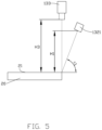
FIG. 5 is a schematic diagram of a red light strip in a second state, a camera assembly, and the product, in another embodiment of the present disclosure.
FIG. 6 is a schematic diagram of a white light strip in a first state, a camera assembly, and the product, in an embodiment of the present disclosure.
FIG. 7 is a schematic diagram of a white light strip in a second state, a camera assembly, and the product, in another embodiment of the present disclosure.
FIG. 8 is a schematic diagram of a white light strip in a third state, a camera assembly, and the product, in another embodiment of the present disclosure.
DETAILED DESCRIPTION
The technical solutions in the embodiments of the present disclosure will be described in conjunction with the accompanying drawings in the embodiments of the present disclosure. Obviously, the described embodiments are part of the embodiments of the present disclosure, not all of them. Based on the embodiments of the present disclosure, all other embodiments obtained by those of ordinary skill in the art without creative work shall fall within the protection scope of the present disclosure.
In the description of the present disclosure, it should be understood that the azimuth or positional relationship indicated by the terms “center”, “longitudinal”, “transverse”, “length”, “width”, “thickness”, “upper”, “lower”, “front”, “rear”, “left”, “right”, “vertical”, “horizontal”, “top”, “bottom”, “inner”, “outer”, “clockwise” and “counterclockwise”, is based on the azimuth or positional relationship shown in the attached drawings, which are only for the convenience of describing the present disclosure and simplifying the description, rather than indicating or implying that the device or element must have a specific orientation, or be constructed and operated in a specific orientation, so it cannot be understood as a limitation of the present disclosure.
The terms “first” and “second” are only used for descriptive purposes and cannot be understood as indicating or implying relative importance or implicitly indicating the number of indicated technical features. Thus, the features defining “first” and “second” may explicitly or implicitly include one or more of the features. In the description of the present disclosure, “multiple” means two or more, unless otherwise expressly and specifically defined.
In the description of the present disclosure, it should be noted that, unless otherwise clearly specified and limited, the terms “install”, “connect” and “connection” should be understood in a broad sense, for example, it can be fixed connection, removable connection, or integrated connection. It can be mechanical connection, electrical connection or duplex communication. It can be directly connected or indirectly connected through an intermediate medium. It can be a connection within two elements or the interaction relationship between two elements.
In the present disclosure, unless otherwise expressly provided and limited, the first feature “above” or “below” of the second feature may include direct contact between the first and second features, or the first and second features may not be in direct contact, but through another feature contact between them. Moreover, if the first feature is “above”, “above” and “above” of the second feature, this may include the first feature being directly above and obliquely above the second feature, or only indicating that the horizontal height of the first feature is higher than the second feature. If the first feature is “below”, “below” and “below” of the second feature, this may include the first feature being directly above and obliquely above the second feature, or only indicating that the horizontal height of the first feature is less than that of the second feature.
The following disclosure provides many different embodiments or examples to implement different structures of the present application. In order to simplify the disclosure of the present application, the components and settings of specific examples are described below. These are merely examples and are not intended to limit the present application. In addition, the present application may repeat reference numbers and reference letters in different examples for the purpose of simplification and clarity, which itself does not indicate a relationship between the various embodiments and settings discussed.
FIG. 1 illustrates a detecting device 10 in accordance with an embodiment of the present disclosure.
The detecting device 10 is used to detect scratches, lines in materials, 3D collapses, 3D grinding marks, depressions, burrs, stamping depressions, knife and cut marks, and other defects which are on a front 21 of a product 20. The product 20 has a square structure, a length direction of the product 20 arranged on the detecting device 10 is defined as a first direction, a width direction of the product 20 is defined as a second direction, and the second direction is perpendicular to the first direction. The product 20 can be an electronic device, such as mobile phone or tablet. When in use, the uppermost side of product 20 is the front 21 of the product 20.
Referring to FIG. 2 , the detecting device 10 includes a transmitting mechanism 11, a supporting mechanism 12, a detecting mechanism 13, and a processor 14. The transmitting mechanism 11 is used to carry and transmit the product 20. The transmitting mechanism 11 is arranged on the supporting mechanism 12. The detecting mechanism 13 includes a detecting frame 131, a light source assembly 132, and a camera assembly 133. The detecting frame 131 is arranged on the supporting mechanism 12 to move in the first direction and the second direction, and the light source assembly 132 is connected to the detecting frame 131. The light source assembly 132 includes two red light strips 1321 and two white light strips 1322. The included angle between the light emitted by the two red light strips 1321 and the front 21 of the product 20 is an acute angle. The included angle between the white light strip 1322 and the front 21 of the product 20 is an acute angle, and the two red light strips 1321 are arranged along the first direction. The two white light strips 1322 are arranged along the second direction. The camera assembly 133 is connected to the detecting frame 131. The image taking direction of the camera assembly 133 is perpendicular to the front 21 of the product 20, and the camera assembly 133 is used to obtain an image of the product 20 under the light of the light source assembly 132. The processor 14 is connected to the camera assembly 133, and the processor 14 is used to process the image of the product 20 to analyze the front 21 of the product 20. The camera assembly 133 can be an array of cameras.
The detecting device 10 uses the camera assembly 133 to obtain the image of the front 21 of the product 20 under the two red light strips 1321 and the two white light strips 1322. The detecting device 10 processes the obtained image through the processor 14. Therefore, the detecting device 10 uses the camera assembly 133 to cooperate with two red light strips 1321 and two white light strips 1322, to obtain the image of the front 21 of the product 20, and uses the processor 14 to automatically identify defects, which improves the accuracy of analysis and saves labor cost.
The above processing of the image obtained by the processor 14 refers to comparing the obtained image with the standard image of a perfect product prestored in the processor 14, by using the discrimination model in the processor to determine defects such as scratches, material lines, 3D collapse, 3D grinding marks, depressions, burrs, stamping depressions, knife marks, and other defects revealed in the image. The formation process of the discrimination model is roughly as follows: train the computer to learn the scratches, material lines, 3D collapse, 3D grinding marks, depressions, burrs, stamping depressions, knife marks and other defects on the front 21 of the product 20 (for example, features showing defects revealed in an image), establish a learning model for the learned content, and form the learned image information into a standard image library stored in the processor 14, and a discrimination model for determining positive defects of products, established according to the standard image database. The processor 14 may be a microcomputer.
In one embodiment, the processor 14 may be a microcomputer with the functions of calculating and storing images, and the processor 14 may be connected to external devices to cooperate with the detecting device 10 to complete the corresponding work.
In one embodiment, the supporting mechanism 12 includes a supporting platform 121, a supporting frame 122, and a moving member 123. The transmitting mechanism 11 is arranged on the supporting platform 121. The supporting frame 122 is connected to the supporting platform 121, and the supporting frame 122 includes two gantry carriages 1221 arranged symmetrically. The two gantry carriages 1221 extend along the first direction, and each gantry carriage 1221 is provided with a first guiding rail 1222. The moving member 123 is slidably connected to the first guiding rail 1222, the moving member 123 is provided with a second guiding rail 1231 arranged along the second direction, and the detecting frame 131 is slidably connected to the second guiding rail 1231.
The supporting platform 121 can be connected to an external device to cooperate with the detecting device 10 to complete the operation.
In one embodiment, the transmitting mechanism 11 includes a transmitting bracket 111 and a transmitting belt 112. The transmitting bracket 111 is arranged on the supporting platform 121 and is located between two gantry carriages 1221. After the product 20 is placed on the transmitting belt 112, the length direction of the product 20 is consistent with the transmission direction of the transmitting belt 112. The transmitting bracket 111 and the transmitting belt 112 can be extended on the supporting platform 121 according to the actual needs to adapt to the external device and cooperate with the detecting device 10 to complete the operation.
In one embodiment, the detecting frame 131 includes a fixing plate 1311, a first detecting rack 1312, and a second detecting rack 1313. The first detecting rack 1312 is connected to the fixing plate 1311, and the camera assembly 133 is connected to the first detecting rack 1312. The second detecting rack 1313 is slidably connected with the first detecting rack 1312 along the third direction, the light source assembly 132 is connected to the second detecting rack 1313, the third direction, the first direction, and the second direction being perpendicular to each other. The first detecting rack 1312 includes a first detecting rod 1312 a, a detecting track 1312 b, and an adjusting block 1312 c. One end of the first detecting rod 1312 a is connected to the fixing plate 1311, the detecting track 1312 b is fixedly connected to the first detecting rod 1312 a, and the length direction of the detecting track 1312 b is arranged along the third direction. One end of the adjusting block 1312 c is slidably connected to the detecting track 1312 b, and the other end of the adjusting block 1312 c is connected to the camera assembly 133, wherein the third direction, the first direction, and the second direction are perpendicular to each other.
The second detecting rack 1313 is slidably connected with the detecting track 1312 b in a hollow rectangular structure. Two red light strips 1321 and two white light strips 1322 are arranged on the second detecting rack 1313, and the two red light strips 1321 are symmetrically arranged. The two white light strips 1322 are also symmetrically arranged.
The first direction is the extension direction of the first guiding rail 1222, that is the X axis in FIG. 1 , the second direction is the extension direction of the second guiding rail 1231, that is the Y axis in FIG. 1 , and the third direction is the extension direction of the detecting track 1312 b, that is the Z axis in FIG. 1 .
Referring to FIG. 3 , when the front 21 of the product 20 is detected by the detecting device 10, the front 21 is divided into a first front 211, a second front 212, a third front 213, a fourth front 214, a fifth front 215, and a sixth front 216, as FIG. 3 shows. The first front 211, the second front 212, and the third front 213 are arranged along the length direction of the product 20, and the first front 211 and the sixth front 216 are arranged along the width direction of the product 20.
In another embodiment, the front 21 can also be divided into other areas.
Referring to FIG. 4 and FIG. 5 , in one embodiment, the detecting device 10 satisfies the relationship: 30°<θ1<60°.
θ1 is the included angle between the light emitted by each red light strip 1321 and the front 21 of the product 20, and θ1 can be 40° and 50°.
In one embodiment, the detecting device 10 satisfies the relationship H1=(0.4−0.8)*[(a+b)/2].
H1 is the distance from each red light strip 1321 along the third direction to the front 21 of the product 20, a is the length of the product 20, and b is the width of the product 20.
In the embodiment, the distance and included angle between the red light strip 1321 in the detecting mechanism 13 and the front 21 of the product 20 are configured to achieve a better image.
The detecting device 10 satisfies the relationship H3=(0.7˜1.7)*[(a+b)/2].
H3 is the distance from the camera assembly 133 along the third direction to the front 21 of the product 20, a is the length of the product 20, and B is the width of the product 20.
In the embodiment, the distance between the camera assembly 133 in the detecting mechanism 13 and the front 21 of the product 20 is configured to achieve a better result by the camera assembly.
Referring to FIG. 3 to FIG. 5 , during detection, the moving member 123 is driven to move on the first guiding rail 1222 manually or through powered components (such as cylinder or motor), so that the light emitted by the two red light strips 1321 covers the first front 211 and the third front 213. At this time, the images of the first front 211 and the third front 213 in the front 21 are obtained through the camera assembly 133. The first detecting rack 1312 is driven manually or through the powered components to drive the fixing plate 1311 to slide on the second guiding rail 1231, so that the light emitted by the two red light strips 1321 covers the fourth front 214 and the sixth front 216. At this time, the images of the fourth front 214 and the sixth front 216 in the front 21 are obtained through the camera assembly 133.
In this way, the images of the first front 211, the third front 213, the fourth front 214, and the sixth front 216 form an image, and the processor 14 preprocesses the obtained image obtained to determine the existence of defects such as edge collapse, and scratches in the front 21.
In another embodiment, the order in which the images of the first front 211, the third front 213, the fourth front 214, and the sixth front 216 are obtained can be changed. As long as the camera assembly 133 can obtain an image when the light emitted by the two red light strips 1321 covers the front part.
Referring to FIG. 6 and FIG. 7 , in one embodiment, the detecting device 10 satisfies the relationship: 30°<θ2<60°.
θ2 is the included angle between the light emitted by the white light strips 1322 and the front 21 of the product 20, and θ2 can be 40° or 50°
In one embodiment, the detecting device 10 satisfies the relationship H2=(0.4−0.8)*[(a+b)/2].
H2 is the distance from each white light strip 1322 along the third direction to the front 21 of the product 20, a is the length of the product 20, and b is the width of the product 20.
In the embodiment, the distance between the white light strips 1322 in the detecting mechanism 13 and the front 21 of the product 20 and the included angle are configured to achieve a better image.
Referring to FIG. 8 , during detection, the moving member 123 is driven to move in the positive direction on the first guiding rail 1222 manually or through the powered components so that the light emitted by the two white light strips 1322 covers the first front 211, the second front 212, and the third front 213. The first detecting rack 1312 is driven manually or through the powered components to drive the fixing plate 1311 to slide on the second guiding rail 1231, so that the light emitted by the two white light strips 1322 is transferred from the third front 213 to the fourth front 214. Manually or through the powered components the moving member 123 is moved in the opposite direction on the first guiding rail 1222, so that the light emitted by the two white light strips 1322 covers the fifth front 215 and the sixth front 216. In this process, images of the first front 211, the second front 212, the third front 213, the fourth front 214, the fifth front 215, and the sixth front 216 in the front 21 are obtained by using the camera assembly 133.
In this way, the obtained images of the first front 211, the second front 212, the third front 213, the fourth front 214, the fifth front 215, and the sixth front 216 form an image, and the processor 14 processes the obtained image to determine the presence of defects such as material lines, 3D grinding marks, depressions, burrs, stamping depressions, knife marks and other defect on the front 21.
Those of ordinary skill in the art should realize that the above embodiments are only used to illustrate the present disclosure, but not to limit the present disclosure. As long as they are within the essential spirit of the present disclosure, the above embodiments are appropriately made. Changes and modifications are to fall within the scope of protection of the present disclosure.

Claims (19)

What is claimed is:
1. A detecting device of detecting a surface of a product, the detecting device comprising:
a supporting mechanism;
a transmitting mechanism carrying and transmitting the product; wherein the transmitting mechanism is arranged on the supporting mechanism, and an upward side of the product is a front of the product;
a detecting mechanism comprising a detecting frame, a light source assembly, and a camera assembly, and wherein length direction of the product arranged on the detecting device is defined as a first direction, width direction of the product is defined as a second direction, and the second direction is perpendicular to the first direction; wherein the detecting frame is arranged on the supporting mechanism to move along the first direction and the second direction, the light source assembly is connected to the detecting frame; the light source assembly comprises two red light strips and two white light strips, an included angle between light emitted by the two red light strips and the front of the product is an acute angle, and the included angle between the two white light strips and the front of the product is an acute angle, the two red light strips are arranged along the first direction, and the two white light strips are arranged along the second direction, the camera assembly is connected to the detecting frame; wherein and an image capturing direction of the camera assembly is perpendicular to the front of the product, and the camera assembly obtains an image of the front of the product under the light of the light source assembly; and
a processor connecting to the camera assembly and preprocessing the image of the front of the product, to obtain a detection result of the front of the product.
2. The detecting device of claim 1, wherein:
the detecting device satisfies a relationship of 30°<θ1<60°;
wherein θ1 is the included angle between the light emitted by each of the two red light strips and the front of the product.
3. The detecting device of claim 1, wherein:
the detecting device satisfies a relationship of 30°<θ2<60°;
wherein θ2 is the included angle between the light emitted by the white light strip and the front of the product.
4. The detecting device of claim 1, wherein:
the detecting device satisfies a relationship of H1=(0.4˜0.8)*[(a+b)/2];
wherein H1 is a distance from each of the two red light strips in the third direction to the front of the product, the third direction is perpendicular to the front of the product, a is a length of the product, and b is a width of the product.
5. The detecting device of claim 4, wherein:
the detecting device satisfies the relationship of H2=(0.4˜0.8)*[(a+b)/2];
wherein H2 is a distance from each of the white light strip in the third direction to the front of the product, a is the length of the product, and b is the width of the product.
6. The detecting device of claim 5, wherein:
the detecting device satisfies the relationship of H3=(0.7˜1.7)*[(a+b)/2];
wherein H3 is a distance from the camera assembly in the third direction to the front of the product, a is the length of the product, and b is the width of the product.
7. The detecting device of claim 1, wherein:
the supporting mechanism comprises a supporting platform, a supporting frame, and a moving member, the transmitting mechanism is arranged on the supporting platform, the supporting frame is connected to the supporting platform, the supporting frame comprises a first guiding rail, and the first guiding rail is parallel to the first direction; the moving member is connected to the first guiding rail, the moving member comprises a second guiding rail, the second guiding rail is parallel to the second direction, the detecting frame is connecting to the second guiding rail.
8. The detecting device of claim 7, wherein:
the detecting frame comprises a fixing plate, a first detecting rack, and a second detecting rack; the fixing plate is connected to the second guiding rail, the first detecting rack is connected to the fixing plate, the camera assembly is connected to the first detecting rack, the second detecting frame is slidably connected with the first detecting rack along the third direction, the light source assembly is connected to the second detecting rack, and the third direction, the first direction and the second direction are perpendicular to each other.
9. The detecting device of claim 8, wherein:
the first detecting rack comprises a first detecting rod, a detecting track and an adjusting block, the first detecting rod is connected to the fixing plate, the detecting track is connected to the first detecting rod, an extension direction of the detecting track is parallel to the third direction, a first end of the adjusting block is slidably connected to the detecting track, a second end of the adjusting block is connected to the camera assembly.
10. The detecting device of claim 8, wherein: the transmitting mechanism comprises a transmitting bracket, and the transmitting bracket is arranged on the supporting platform and is located between two gantry carriages.
11. A detecting device for detecting a surface of a product, the detecting device comprising:
a supporting mechanism;
a transmitting mechanism carrying and transmitting the product; wherein the transmitting mechanism is arranged on the supporting mechanism, and an upward side of the product is a front of the product;
a detecting mechanism comprising a detecting frame, a light source assembly, and a camera assembly, and wherein length direction of the product arranged on the detecting device is defined as a first direction, width direction of the product is defined as a second direction, and the second direction is perpendicular to the first direction; wherein the detecting frame is arranged on the supporting mechanism to move along the first direction and the second direction, the light source assembly is connected to the detecting frame; the light source assembly comprises two red light strips and two white light strips, an included angle between light emitted by the two red light strips and the front of the product is an acute angle, and the included angle between the two white light strips and the front of the product is an acute angle, the two red light strips are arranged along the first direction, and the two white light strips are arranged along the second direction, the camera assembly is connected to the detecting frame; wherein and an image capturing direction of the camera assembly is perpendicular to the front of the product, and the camera assembly obtains an image of the front of the product under the light of the light source assembly; and
a processor connecting to the camera assembly and preprocessing the image of the front of the product, to obtain a detection result of the front of the product;
wherein the supporting mechanism comprises a supporting platform, a supporting frame, and a moving member, the transmitting mechanism is arranged on the supporting platform, the supporting frame is connected to the supporting platform, the supporting frame comprises a first guiding rail, and the first guiding rail is parallel to the first direction; the moving member is connected to the first guiding rail, the moving member comprises a second guiding rail, the second guiding rail is parallel to the second direction, the detecting frame is connecting to the second guiding rail.
12. The detecting device of claim 11, wherein:
the detecting device satisfies a relationship of 30°<θ1<60°;
wherein θ1 is the included angle between the light emitted by each of the two red light strips and the front of the product.
13. The detecting device of claim 12, wherein:
the detecting device satisfies a relationship of 30°<θ2<60°;
wherein θ2 is the included angle between the light emitted by the white light strip and the front of the product.
14. The detecting device of claim 11, wherein:
the detecting device satisfies a relationship of H1=(0.4˜0.8)*[(a+b)/2];
wherein H1 is a distance from each of the two red light strips in the third direction to the front of the product, the third direction is perpendicular to the front of the product, a is a length of the product, and b is a width of the product.
15. The detecting device of claim 14, wherein:
the detecting device satisfies the relationship of H2=(0.4˜0.8)*[(a+b)/2];
wherein H2 is a distance from each of the white light strip in the third direction to the front of the product, a is the length of the product, and b is the width of the product.
16. The detecting device of claim 15, wherein:
the detecting device satisfies the relationship of H3=(0.7˜1.7)*[(a+b)/2];
wherein H3 is a distance from the camera assembly in the third direction to the front of the product, a is the length of the product, and b is the width of the product.
17. The detecting device of claim 11, wherein:
the detecting frame comprises a fixing plate, a first detecting rack, and a second detecting rack; the fixing plate is connected to the second guiding rail, the first detecting rack is connected to the fixing plate, the camera assembly is connected to the first detecting rack, the second detecting frame is slidably connected with the first detecting rack along the third direction, the light source assembly is connected to the second detecting rack, and the third direction, the first direction and the second direction are perpendicular to each other.
18. The detecting device of claim 17, wherein:
the first detecting rack comprises a first detecting rod, a detecting track and an adjusting block, the first detecting rod is connected to the fixing plate, the detecting track is connected to the first detecting rod, an extension direction of the detecting track is parallel to the third direction, a first end of the adjusting block is slidably connected to the detecting track, a second end of the adjusting block is connected to the camera assembly.
19. The detecting device of claim 17, wherein: the transmitting mechanism comprises a transmitting bracket, and the transmitting bracket is arranged on the supporting platform and is located between two gantry carriages.
US17/544,758 2021-05-19 2021-12-07 Device for recognizing defects remaining in finished surface of product Active 2042-05-19 US11796483B2 (en)

Applications Claiming Priority (2)

Application Number Priority Date Filing Date Title
CN202121073966.X 2021-05-19
CN202121073966.XU CN215574704U (en) 2021-05-19 2021-05-19 Detection device

Publications (2)

Publication Number Publication Date
US20220373469A1 US20220373469A1 (en) 2022-11-24
US11796483B2 true US11796483B2 (en) 2023-10-24

Family

ID=79862125

Family Applications (1)

Application Number Title Priority Date Filing Date
US17/544,758 Active 2042-05-19 US11796483B2 (en) 2021-05-19 2021-12-07 Device for recognizing defects remaining in finished surface of product

Country Status (2)

Country Link
US (1) US11796483B2 (en)
CN (1) CN215574704U (en)

Cited By (2)

* Cited by examiner, † Cited by third party
Publication number Priority date Publication date Assignee Title
US20220373474A1 (en) * 2021-05-19 2022-11-24 Fu Tai Hua Industry (Shenzhen) Co., Ltd. Device for recognizing defects in finished surface of product
US12385852B2 (en) * 2022-07-25 2025-08-12 Samsung Display Co., Ltd. Glass inspection equipment and method of glass inspection

Families Citing this family (2)

* Cited by examiner, † Cited by third party
Publication number Priority date Publication date Assignee Title
CN215574703U (en) * 2021-05-19 2022-01-18 富泰华工业(深圳)有限公司 Detection device
CN116008312A (en) * 2022-12-19 2023-04-25 深圳市日联科技有限公司 Product positioning device for lithium battery X-ray detection

Citations (1)

* Cited by examiner, † Cited by third party
Publication number Priority date Publication date Assignee Title
US11645742B2 (en) * 2019-10-14 2023-05-09 Fu Tai Hua Industry (Shenzhen) Co., Ltd. Electronic device for optically detecting appearance of product for defects

Patent Citations (1)

* Cited by examiner, † Cited by third party
Publication number Priority date Publication date Assignee Title
US11645742B2 (en) * 2019-10-14 2023-05-09 Fu Tai Hua Industry (Shenzhen) Co., Ltd. Electronic device for optically detecting appearance of product for defects

Cited By (3)

* Cited by examiner, † Cited by third party
Publication number Priority date Publication date Assignee Title
US20220373474A1 (en) * 2021-05-19 2022-11-24 Fu Tai Hua Industry (Shenzhen) Co., Ltd. Device for recognizing defects in finished surface of product
US11982629B2 (en) * 2021-05-19 2024-05-14 Fu Tai Hua Industry (Shenzhen) Co., Ltd. Device for recognizing defects in finished surface of product
US12385852B2 (en) * 2022-07-25 2025-08-12 Samsung Display Co., Ltd. Glass inspection equipment and method of glass inspection

Also Published As

Publication number Publication date
US20220373469A1 (en) 2022-11-24
CN215574704U (en) 2022-01-18

Similar Documents

Publication Publication Date Title
US11796483B2 (en) Device for recognizing defects remaining in finished surface of product
US11798155B2 (en) Device for recognizing defects remaining in finished surface of product in images taken under multiple colors of light
US11940389B2 (en) Device for recognizing defects in finished surface of product
CN110321836B (en) A detection method for conveying materials based on images and laser point cloud images
CN110508503A (en) A kind of product detection device based on machine vision
CN217717531U (en) Detection device and battery manufacturing equipment
CN116258718B (en) Welding quality detection method, system, equipment and medium based on 3D camera
US11982629B2 (en) Device for recognizing defects in finished surface of product
CN109590952B (en) Intelligent detection method and detection workbench for complete sets of process assembly boards
CN107797517A (en) The method and system detected using realizing of Robot Vision steel band punching processing
CN109990722A (en) A bottle cap inspection equipment
CN112255243B (en) Portable detection device and detection method for surface quality of continuous casting billet finished product
CN213337366U (en) A kind of wooden board visual inspection camera structure
CN111982909A (en) A kind of wood board visual inspection equipment and inspection method
CN111473732B (en) Motor long and short shaft automatic identification system, cover riveting machine and automatic identification method
CN111043987A (en) Concrete test piece parameter measuring device and method based on vision
CN111921890A (en) A Novel Image Screening Mechanism and Using Method
CN111818269A (en) A kind of identification method and identification system of vehicle certificate
CN110132182A (en) Automatic detection device for eccentricity of camera of handheld equipment
CN217541806U (en) Aluminum alloy template discernment detection device
CN217277937U (en) Multi-channel optical detection device for middle frame of mobile phone
CN113640303B (en) Surface flaw inspection equipment for notebook computer and detection method thereof
CN213337396U (en) A horizontal adjustment device for a wooden board detection platform
CN112595229B (en) Monitoring device for measuring volume of material
CN210952728U (en) Concrete test piece parameter measurement device based on vision

Legal Events

Date Code Title Description
AS Assignment

Owner name: FU TAI HUA INDUSTRY (SHENZHEN) CO., LTD., CHINA

Free format text: ASSIGNMENT OF ASSIGNORS INTEREST;ASSIGNORS:HU, LIU-BIN;YANG, WEI;REEL/FRAME:058328/0371

Effective date: 20211204

FEPP Fee payment procedure

Free format text: ENTITY STATUS SET TO UNDISCOUNTED (ORIGINAL EVENT CODE: BIG.); ENTITY STATUS OF PATENT OWNER: LARGE ENTITY

STPP Information on status: patent application and granting procedure in general

Free format text: DOCKETED NEW CASE - READY FOR EXAMINATION

STPP Information on status: patent application and granting procedure in general

Free format text: NOTICE OF ALLOWANCE MAILED -- APPLICATION RECEIVED IN OFFICE OF PUBLICATIONS

STPP Information on status: patent application and granting procedure in general

Free format text: PUBLICATIONS -- ISSUE FEE PAYMENT VERIFIED

STCF Information on status: patent grant

Free format text: PATENTED CASE