US11794433B2 - In-vehicle three dimensional (3D) printer control - Google Patents
In-vehicle three dimensional (3D) printer control Download PDFInfo
- Publication number
- US11794433B2 US11794433B2 US17/023,647 US202017023647A US11794433B2 US 11794433 B2 US11794433 B2 US 11794433B2 US 202017023647 A US202017023647 A US 202017023647A US 11794433 B2 US11794433 B2 US 11794433B2
- Authority
- US
- United States
- Prior art keywords
- vehicle
- printer
- tire
- computer
- additive material
- Prior art date
- Legal status (The legal status is an assumption and is not a legal conclusion. Google has not performed a legal analysis and makes no representation as to the accuracy of the status listed.)
- Active, expires
Links
Images


Classifications
-
- B—PERFORMING OPERATIONS; TRANSPORTING
- B29—WORKING OF PLASTICS; WORKING OF SUBSTANCES IN A PLASTIC STATE IN GENERAL
- B29D—PRODUCING PARTICULAR ARTICLES FROM PLASTICS OR FROM SUBSTANCES IN A PLASTIC STATE
- B29D30/00—Producing pneumatic or solid tyres or parts thereof
- B29D30/06—Pneumatic tyres or parts thereof (e.g. produced by casting, moulding, compression moulding, injection moulding, centrifugal casting)
- B29D30/52—Unvulcanised treads, e.g. on used tyres; Retreading
- B29D30/54—Retreading
-
- B—PERFORMING OPERATIONS; TRANSPORTING
- B29—WORKING OF PLASTICS; WORKING OF SUBSTANCES IN A PLASTIC STATE IN GENERAL
- B29C—SHAPING OR JOINING OF PLASTICS; SHAPING OF MATERIAL IN A PLASTIC STATE, NOT OTHERWISE PROVIDED FOR; AFTER-TREATMENT OF THE SHAPED PRODUCTS, e.g. REPAIRING
- B29C64/00—Additive manufacturing, i.e. manufacturing of three-dimensional [3D] objects by additive deposition, additive agglomeration or additive layering, e.g. by 3D printing, stereolithography or selective laser sintering
- B29C64/10—Processes of additive manufacturing
- B29C64/106—Processes of additive manufacturing using only liquids or viscous materials, e.g. depositing a continuous bead of viscous material
-
- B—PERFORMING OPERATIONS; TRANSPORTING
- B29—WORKING OF PLASTICS; WORKING OF SUBSTANCES IN A PLASTIC STATE IN GENERAL
- B29C—SHAPING OR JOINING OF PLASTICS; SHAPING OF MATERIAL IN A PLASTIC STATE, NOT OTHERWISE PROVIDED FOR; AFTER-TREATMENT OF THE SHAPED PRODUCTS, e.g. REPAIRING
- B29C64/00—Additive manufacturing, i.e. manufacturing of three-dimensional [3D] objects by additive deposition, additive agglomeration or additive layering, e.g. by 3D printing, stereolithography or selective laser sintering
- B29C64/30—Auxiliary operations or equipment
- B29C64/386—Data acquisition or data processing for additive manufacturing
- B29C64/393—Data acquisition or data processing for additive manufacturing for controlling or regulating additive manufacturing processes
-
- B—PERFORMING OPERATIONS; TRANSPORTING
- B29—WORKING OF PLASTICS; WORKING OF SUBSTANCES IN A PLASTIC STATE IN GENERAL
- B29C—SHAPING OR JOINING OF PLASTICS; SHAPING OF MATERIAL IN A PLASTIC STATE, NOT OTHERWISE PROVIDED FOR; AFTER-TREATMENT OF THE SHAPED PRODUCTS, e.g. REPAIRING
- B29C73/00—Repairing of articles made from plastics or substances in a plastic state, e.g. of articles shaped or produced by using techniques covered by this subclass or subclass B29D
-
- G—PHYSICS
- G06—COMPUTING; CALCULATING OR COUNTING
- G06T—IMAGE DATA PROCESSING OR GENERATION, IN GENERAL
- G06T7/00—Image analysis
- G06T7/50—Depth or shape recovery
- G06T7/55—Depth or shape recovery from multiple images
- G06T7/579—Depth or shape recovery from multiple images from motion
-
- G—PHYSICS
- G06—COMPUTING; CALCULATING OR COUNTING
- G06T—IMAGE DATA PROCESSING OR GENERATION, IN GENERAL
- G06T7/00—Image analysis
- G06T7/60—Analysis of geometric attributes
- G06T7/62—Analysis of geometric attributes of area, perimeter, diameter or volume
-
- G—PHYSICS
- G06—COMPUTING; CALCULATING OR COUNTING
- G06T—IMAGE DATA PROCESSING OR GENERATION, IN GENERAL
- G06T7/00—Image analysis
- G06T7/60—Analysis of geometric attributes
- G06T7/68—Analysis of geometric attributes of symmetry
-
- B—PERFORMING OPERATIONS; TRANSPORTING
- B29—WORKING OF PLASTICS; WORKING OF SUBSTANCES IN A PLASTIC STATE IN GENERAL
- B29C—SHAPING OR JOINING OF PLASTICS; SHAPING OF MATERIAL IN A PLASTIC STATE, NOT OTHERWISE PROVIDED FOR; AFTER-TREATMENT OF THE SHAPED PRODUCTS, e.g. REPAIRING
- B29C73/00—Repairing of articles made from plastics or substances in a plastic state, e.g. of articles shaped or produced by using techniques covered by this subclass or subclass B29D
- B29C73/02—Repairing of articles made from plastics or substances in a plastic state, e.g. of articles shaped or produced by using techniques covered by this subclass or subclass B29D using liquid or paste-like material
-
- B—PERFORMING OPERATIONS; TRANSPORTING
- B29—WORKING OF PLASTICS; WORKING OF SUBSTANCES IN A PLASTIC STATE IN GENERAL
- B29L—INDEXING SCHEME ASSOCIATED WITH SUBCLASS B29C, RELATING TO PARTICULAR ARTICLES
- B29L2030/00—Pneumatic or solid tyres or parts thereof
- B29L2030/002—Treads
-
- B—PERFORMING OPERATIONS; TRANSPORTING
- B33—ADDITIVE MANUFACTURING TECHNOLOGY
- B33Y—ADDITIVE MANUFACTURING, i.e. MANUFACTURING OF THREE-DIMENSIONAL [3-D] OBJECTS BY ADDITIVE DEPOSITION, ADDITIVE AGGLOMERATION OR ADDITIVE LAYERING, e.g. BY 3-D PRINTING, STEREOLITHOGRAPHY OR SELECTIVE LASER SINTERING
- B33Y10/00—Processes of additive manufacturing
-
- B—PERFORMING OPERATIONS; TRANSPORTING
- B33—ADDITIVE MANUFACTURING TECHNOLOGY
- B33Y—ADDITIVE MANUFACTURING, i.e. MANUFACTURING OF THREE-DIMENSIONAL [3-D] OBJECTS BY ADDITIVE DEPOSITION, ADDITIVE AGGLOMERATION OR ADDITIVE LAYERING, e.g. BY 3-D PRINTING, STEREOLITHOGRAPHY OR SELECTIVE LASER SINTERING
- B33Y30/00—Apparatus for additive manufacturing; Details thereof or accessories therefor
-
- B—PERFORMING OPERATIONS; TRANSPORTING
- B33—ADDITIVE MANUFACTURING TECHNOLOGY
- B33Y—ADDITIVE MANUFACTURING, i.e. MANUFACTURING OF THREE-DIMENSIONAL [3-D] OBJECTS BY ADDITIVE DEPOSITION, ADDITIVE AGGLOMERATION OR ADDITIVE LAYERING, e.g. BY 3-D PRINTING, STEREOLITHOGRAPHY OR SELECTIVE LASER SINTERING
- B33Y80/00—Products made by additive manufacturing
Definitions
- the present invention relates generally to the field of Internet of Things sensors mounted in motor vehicles (for example, driverless school busses), and also to the field of three dimensional printers.
- tires generally have treads (sometimes herein referred to as road engaging surfaces) over an exterior, cylindrically shaped surface, and that this tread surface is subject to wear from driving the vehicle over roads. It is further known that too much wear can cause the tire to slip, or fail catastrophically, and that this means that tires should be replaced when their treads wear down too much.
- one known way to check tire tread depth for excessive wear is called the penny test. Under the penny test, one inserts a penny into a tire's tread groove with Lincoln's head upside down. If all of Lincoln's head is visible (that is, located outside of the tread groove) the penny test indicates that the tire should be replaced. It is noted that this document should not be taken as an endorsement of this prior art tire tread wear testing method.
- the Wikipedia entry for “3D printing” states as follows: “The 3D printing process builds a three-dimensional object from a computer-aided design (CAD) model, usually by successively adding material layer by layer, which is why it is also called additive manufacturing, unlike conventional machining, casting and forging processes, where material is removed from a stock item (subtractive manufacturing) or poured into a mold and shaped by means of dies, presses and hammers.
- CAD computer-aided design
- 3D printing covers a variety of processes in which material is joined or solidified under computer control to create a three-dimensional object, with material being added together (such as liquid molecules or powder grains being fused together), typically layer by layer. . . .
- FDM frequency division multiplexing
- SLA stereolithography
- SLS selective laser sintering
- FDM is typically the most inexpensive of the three by a large margin, which lends to the popularity of the process.
- 3D printing originally referred to a process that deposits a binder material onto a powder bed with inkjet printer heads layer by layer. More recently, the popular vernacular has started using the term to encompass a wider variety of additive-manufacturing techniques such as electron-beam additive manufacturing and selective laser melting.” (footnotes omitted)
- US patent application 2016/0185040 (“Costlow”) states as follows: “An apparatus, system, and method for disposing green rubber, via 3D Printing or additive manufacturing, are provided.
- the apparatus includes at least a housing, a nozzle, and a heating element. Green rubber is forced through the nozzle and deposited in an iterative build process.
- the apparatus may be used in a variety of applications, including tire applications. . . . Examples of three dimensional structures include, without limitation, bellows, consumer goods, dampers, industrial components (such as gaskets, grommets, or o-rings), shoe components, and tire components (such as a tread or lug).”
- a motor vehicle assembly includes: a vehicle frame; a first tire, with the first tire including a first tread portion; a first three dimensional (3D) printer; and a 3D printer control module.
- the first 3D printer is structured and connected to deposit additive material suitable for replenishing the first tread portion under control of the 3D printer control module.
- the 3D printer is secured to the vehicle frame in a location such that its additive material is deposited on the first tire tread portion.
- a method, computer program product and/or system that performs the following operations (not necessarily in the following order): (i) providing a motor vehicle assembly (MVA) including a vehicle frame, a first tire, with the first tire including a first tread portion, a first three dimensional (3D) printer, and a 3D printer control module, with the first 3D printer being structured and connected to deposit additive material suitable for replenishing the first tread portion under control of the 3D printer control module, and with the 3D printer being secured to the vehicle frame in a location such that its additive material is deposited on the first tire tread portion; (ii) driving the MVA; and (iii) during the driving of the MVA, depositing additive material from the first 3D printer onto the first tread portion to replenish the first tread portion.
- MVA motor vehicle assembly
- a method, computer program product and/or system that performs the following operations (not necessarily in the following order): (i) receiving a sensor data set, from a set of sensor(s), including information indicative of a condition of a first tire tread portion of a first tire of a motor vehicle assembly (MVA) while the MVA is being driven; (ii) determining that the first tire tread portion needs replenishment based, at least in part, upon the sensor data set; and (iii) responsive to the determination that the first tire tread portion needs replenishment, controlling a first 3D printer that is secured with respect to the vehicle frame to deposit additive material on the first tread portion to replenish the first tread portion while the vehicle is being driven.
- MVA motor vehicle assembly
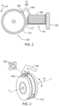
- FIG. 1 is a top view of a portion of a first embodiment of a motor vehicle according to the present invention
- FIG. 2 is a left side view of a front driver side wheel portion of the first embodiment motor vehicle
- FIG. 3 is a perspective view of the front driver side wheel portion of the first embodiment motor vehicle
- FIG. 4 is a side view of a portion of a second embodiment of a motor vehicle according to the present invention.
- FIG. 5 is a perspective view of a wheel portion of the second embodiment motor vehicle
- FIG. 6 is a block diagram of a driverless vehicle control computer
- FIG. 7 is a flow chart of a method.
- Some embodiments of the present invention are directed to a motor vehicle including a 3D printer to add material to the tire tread in a controlled manner to counter tire wear. Also, disclosed is a method of adding additive material to a tire tread, by an in-vehicle 3D printer, while the vehicle is being driven, and computer software for controlling the method of adding additive material to a tire tread, by an in-vehicle 3D printer, while the vehicle is being driven.
- motor vehicle assembly 100 includes: chassis (also sometimes referred to herein as “vehicle frame”) 102 ; front fender sub-assembly 104 ; motor 106 ; driver's seat sub-assembly 110 ; passenger's seat sub-assembly 112 ; front driver side printer-securing recess 116 ; front driver side printer-securing wall 117 ; front passenger side printer-securing recess 118 ; front passenger side printer-securing wall 119 ; front driver side tire sub-assembly 120 (which rotates in the R 1 direction about axis A and has a tire width in the dimension W); front driver side tire tread surface 121 ; front passenger side tire sub-assembly 122 (which rotates in the R 1 direction about axis A and has a tire width in the dimension W); front passenger side tire tread surface 123 ; driverless vehicle control computer 132 ; electrical power sub-assembly 134
- Vehicle frame 102 , front fender sub-assembly 104 , motor 106 , driver's seat sub-assembly 110 , passenger's seat sub-assembly 112 , electrical power sub-assembly 134 and passenger compartment floor member 136 are vehicle components that are the same as the they are in conventional vehicles. In various embodiments, these components may take a wide variety of forms now known or to be developed in the future.
- motor 106 is an internal combustion engine, but could also be an electric motor or a hybrid motor.
- the seats could be omitted (for example, in driverless vehicle embodiments used for package deliveries).
- At least some embodiments of the present invention focus on features such as the printer-securing recesses 116 , 118 , tire tread surfaces 121 , 123 , driverless vehicle control computer 132 , 3D printer control communication lines 138 , 3D printer power lines 139 , 3D printer 140 and cameras 150 , 152 .
- the vehicle may have more, or fewer, than four tires. In some embodiments, it may be only a subset of the tires that can have their respective treads replenished by the 3D printer. As will be discussed below, in connection with the embodiment of FIGS. 4 and 5 , there may be a separate, dedicated 3D printer for each tire. In assembly 100 , the 3D printer must be physically moved from the position shown in FIG.
- the 3D printer could be moved by electromechanical devices or a robot.
- FIG. 2 shows the 3D printer as it is positioned in recess 116 in order to replenish tread 121 with additive material 144 .
- the additive material dries and cures sufficiently quickly so that the tread may be replenished by thin layer(s) of additive material 144 so long as the vehicle is being driven between 5 and 15 miles per hour.
- some embodiments may not be able to be used when the vehicle is being driven (for example, some embodiments may require that the tire to be replenished is suspended above the ground surface by a jack).
- the print head of 3D printer 140 takes the form of a row of nozzles that extends in the W direction all the way across the width of the tire. This way, the print head does not need to move relative to the 3D printer.
- the print head may be structured to move in the W direction, and/or in the radial direction of the tire, while tread replenishment printing is taking place.
- electrical power sub-assembly 134 which provides electrical power to electrical components of vehicle 100 also powers 3D printer 140 through printer power lines 139 when the printer is secured in any of the recesses 116 , 119 .
- the 3D printer(s) may be battery powered.
- camera 150 intermittently sends video images of tread 121 to driverless vehicle control computer (DVCC) 132 , which has machine logic (not separately shown) to determine when portions of tread 121 have worn down and require replenishment.
- DVCC driverless vehicle control computer
- other types of sensors other than video cameras, may be used to monitor the tire to: (i) detect that tread replenishment is needed; and/or (ii) monitor the tread replenishment operation as it takes place.
- the DVCC alerts the occupants of the vehicle and instructs them to place 3d printer 140 in the printer recess proximate to the front driver side tire, which, in this example is recess 116 .
- FIG. 2 shows 3D printer 140 in place after it has been put in recess 116 .
- the tread is replenished with additive material 144 through nozzles sub-assembly 142 .
- nozzles sub-assembly 142 extends in the W direction across the entire width of tire 120 .
- the width dimension location(s) of the portions of the tread that need replenishment are determined by the DVCC, which controls 3D printer 140 to lay bead(s) of additive material through the correct nozzles to control the W direction placement of the bead of additive material. Because, in this embodiment, the bead of additive material is applied when the car is being driven, this bead may be controlled to form a very thin layer of new material so that the additive material dries and/or cures sufficiently so that it is not displaced by contact with the roadway as the tire rotates about axis A.
- the machine logic of the DVCC must carefully choose when to lay the bead of replenishment material.
- the machine logic of the DVCC only lays a bead when the following conditions are met: (i) ambient temperature value is between 20 and 80 degrees Fahrenheit; (ii) vehicle speed between 10 and 30 miles per hour; (iii) the roadway is dry; (iv) the angular position of the tire about axis A is an angular position where tread replenishment is required; and (v) the tires are in a straight ahead position (that is, not being steered in a turn).
- the specific values and value ranges in this example are, of course, only illustrative.
- different parameters may be monitored to determine, by machine logic, when to lay the bead of additive material and when to forbear from laying a bead of additive material.
- Ongoing video received from camera 150 allows the DVCC to determine when the replenishment operation is complete because a sufficient number of layers of additive material has respectively been laid in the spots on tread 121 that require it.
- the flow rate of additive material from nozzles 142 is controlled based on the rotational speed of the tire so that each layer of additive material newly deposited on the tread will have: (i) at least approximately the same thickness; and (ii) a sufficiently small thickness so that the additive material dries and cures between the time it is deposited on the tire and the time the newly deposited layer first makes contact with the roadway.
- the additive material may be a pressure curable material so that the compressive force exerted by the roadway upon the tire actually helps the additive material to dry and cure.
- the DVCC instructs the vehicle occupants to put the 3D printer back in its storage location shown in FIG. 1 .
- Some embodiments of the present invention recognize the following facts, potential problems and/or potential areas for improvement with respect to the current state of the art: (i) when vehicles are running on the road, then there will be a wear and tear in the vehicle tires; (ii) the wear and tear of vehicle tire is depending on rubbing force between the road surface and vehicle tire surface; (iii) over a period of a time, if proper maintenance is not done in a timely manner, then there will be a major problem in the vehicle, and it might cause an accident; (iv) if proper maintenance is not done, then because of wear and tear vehicle tires will get damaged, and this might cause accident and damage in the vehicle; and/or (v) there is a need a method and system by which, vehicle tires will be repaired automatically when any defect is detected, so that, near real-time proactive maintenance will be performed on the vehicle tires, and hence, major damage in the vehicle tires can be prevented.
- Some embodiments of the present invention may include one, or more, of the following operations, features, characteristics and/or advantages: (i) method and system for self-repairing vehicle tires; (ii) a method and system which will be using inbuild 3D printing machine along with vehicle tires assembly; (iii) when IoT enabled system detects any defect in the vehicle tire, then vehicle tires will be repaired automatically on near real-time basis; (iv) proactive maintenance will be performed on the vehicle tires, and hence, major damage in the vehicle tires can be prevented in a timely fashion; (v) for some heavy duty vehicles, like transportation vehicles, the changes of tire damage is more, so, some embodiments can identify any changes of damage in a proactive manner; and/or (vi) some embodiments can ratify the changes in tire tread damage before they cause a vehicular accident or catastrophic failure of a tire.
- Some embodiments of the present invention may include one, or more, of the following operations, features, characteristics and/or advantages: (i) IoT (Internet of Things) and ultrasound scanning enabled system will be detecting problem with vehicle tires on real-time basis; (ii) based on pattern of defect and wear and tear, the vehicle tires will automatically be rectified in a timely fashion with inbuilt 3D printing system; (iii) 3D printing modules will be installed in the vehicle chassis, near each vehicle wheel mounting, when any defect is identified, the 3D printing module will be rectifying the defective area; (iv) the propagation of defect in the vehicle tires can be prevented in a timely fashion; and/or (v) based on the pattern of identified defect in the vehicle tires, vehicle speed, current location during the journey, and predicted time required to rectify the defect in the vehicle tires, the autonomous vehicle will be identifying the stop location, so that passenger can take a break, and vehicle can perform self-repairing of the tires with 3D printing method.
- IoT Internet of Things
- ultrasound scanning enabled system will be detecting problem
- Some embodiments of the present invention may include one, or more, of the following operations, features, characteristics and/or advantages: (i) based on the pattern of defect in the vehicle tires, the 3D printing module will be rectifying the problem; (ii) if required, the vehicle will be changing the relative position of the wheels (vehicle will be moving so that wheel can change the position based on rotation), so that rectification can be done in proper places of the vehicle tires; (iii) the IoT and ultrasound scanning system will be evaluating if the proper rectification is done in the vehicle tires, and accordingly the vehicle will be ready for travelling; (iv) based on the relative position and pattern of defect in the vehicle tires, the autonomous vehicle will decide if the vehicle needs to be stopped for repairing or the repairing can be done with running condition; and/or (v) the 3D printing module will also be having a water jet cleaning module, when vehicle tire needs to be corrected, then water jet system will be ensuring proper cleaning of the target area and then 3D printing based correction will be done.
- motor vehicle assembly 500 includes: vehicle frame 501 ; front driver side 3D printer 502 ; front driver side tire 506 ; rear driver side 3D printer 504 ; and rear driver side tire 508 .
- the 3D printing modules will be mounted with the vehicle chassis, and the 3D printing module will be placed over each of the wheels. IoT sensors or camera feed will be analyzing the defect in the vehicle tire, and accordingly printing will be done to rectify the problem.
- Vehicle tires have IoT (Internet of Things) sensor-based modules.
- An autonomous vehicle gathers the IoT sensor feed from each of the vehicle tires, and, accordingly, identifies the pattern of wear and tear or defects in the vehicle tires.
- the vehicle computing system analyzes the IoT feed, and, accordingly, identifies the type of defect with the vehicle tires, like wear and tear, broken, crack is detected, etc. Based on predefined standards about the condition of vehicle tires, the vehicle computing system determines what type of repair is required and priority order for repairing the vehicle tires.
- 3D printing module(s) are attached to repair the vehicle tires. In some embodiments, for each wheel there will be one 3D printing repairing module.
- the 3D printing material will be stored in the vehicle, during 3D printing operation, the printing material will be laid over the defective area of vehicle tire. In some embodiments, the material will be same as the material used for printing vehicle tire.
- Some embodiments of the present invention may include one, or more, of the following operations, features, characteristics and/or advantages: (i) while the vehicle is running, the computing system will be analyzing the pattern of defect the vehicle tire; (ii) an autonomous vehicle identifies the vehicle and travel specific information, like, current speed of the vehicle, current location, and time required to rectify the problem in the vehicle tire; (iii) the autonomous vehicle will be validating if the vehicle needs to be stopped to repair the identified problem with the vehicle tire or during running contrition the repairing can be done; (iv) if the vehicle needs to be stopped, then the vehicle will be identifying appropriate place, or will move in a parking area where the vehicle can perform self-repairing the vehicle tire; (v) the defect type will be analyzed, and will be identifying how long the defect can be sustained without repairing; (vi) when autonomous vehicle identifies immediate repairing is required, then the vehicle will be identifying appropriate place and with 3D printing module rectification will be done; (vii) the 3D printing module will also be having
- Some embodiments of the present invention may include one, or more, of the following operations, features, characteristics and/or advantages: (i) uses an IoT and ultrasound scanning enabled system to detect problems with vehicle tires on a frequent basis (for example, a real time basis); (ii) based on the detected pattern of defect and wear and tear, the vehicle tires will automatically be rectified in a timely fashion with inbuilt 3D printing system; (iii) 3D printing modules will be installed in the vehicle chassis, near each vehicle wheel mounting, when any defect is identified, the 3D printing module will be rectifying the defective area; and/or (iv) the 3D printer will be part of the vehicle chassis, and will be tracking any uneven wear and tear, crack etc., and will be identifying appropriate timing when 3D printing.
- the present invention may be a system, a method, and/or a computer program product at any possible technical detail level of integration
- the computer program product may include a computer readable storage medium (or media) having computer readable program instructions thereon for causing a processor to carry out aspects of the present invention
- the computer readable storage medium can be a tangible device that can retain and store instructions for use by an instruction execution device.
- the computer readable storage medium may be, for example, but is not limited to, an electronic storage device, a magnetic storage device, an optical storage device, an electromagnetic storage device, a semiconductor storage device, or any suitable combination of the foregoing.
- a non-exhaustive list of more specific examples of the computer readable storage medium includes the following: a portable computer diskette, a hard disk, a random access memory (RAM), a read-only memory (ROM), an erasable programmable read-only memory (EPROM or Flash memory), a static random access memory (SRAM), a portable compact disc read-only memory (CD-ROM), a digital versatile disk (DVD), a memory stick, a floppy disk, a mechanically encoded device such as punch-cards or raised structures in a groove having instructions recorded thereon, and any suitable combination of the foregoing.
- RAM random access memory
- ROM read-only memory
- EPROM or Flash memory erasable programmable read-only memory
- SRAM static random access memory
- CD-ROM compact disc read-only memory
- DVD digital versatile disk
- memory stick a floppy disk
- a mechanically encoded device such as punch-cards or raised structures in a groove having instructions recorded thereon
- a computer readable storage medium is not to be construed as being transitory signals per se, such as radio waves or other freely propagating electromagnetic waves, electromagnetic waves propagating through a waveguide or other transmission media (for example, light pulses passing through a fiber-optic cable), or electrical signals transmitted through a wire.
- a “storage device” is hereby defined to be anything made or adapted to store computer code in a manner so that the computer code can be accessed by a computer processor.
- a storage device typically includes a storage medium, which is the material in, or on, which the data of the computer code is stored.
- a single “storage device” may have: (i) multiple discrete portions that are spaced apart, or distributed (for example, a set of six solid state storage devices respectively located in six laptop computers that collectively store a single computer program); and/or (ii) may use multiple storage media (for example, a set of computer code that is partially stored in as magnetic domains in a computer's non-volatile storage and partially stored in a set of semiconductor switches in the computer's volatile memory).
- the term “storage medium” should be construed to cover situations where multiple different types of storage media are used.
- Computer readable program instructions described herein can be downloaded to respective computing/processing devices from a computer readable storage medium or to an external computer or external storage device via a network, for example, the Internet, a local area network, a wide area network and/or a wireless network.
- the network may comprise copper transmission cables, optical transmission fibers, wireless transmission, routers, firewalls, switches, gateway computers and/or edge servers.
- a network adapter card or network interface in each computing/processing device receives computer readable program instructions from the network and forwards the computer readable program instructions for storage in a computer readable storage medium within the respective computing/processing device.
- Computer readable program instructions for carrying out operations of the present invention may be assembler instructions, instruction-set-architecture (ISA) instructions, machine instructions, machine dependent instructions, microcode, firmware instructions, state-setting data, or either source code or object code written in any combination of one or more programming languages, including an object oriented programming language such as Smalltalk, C++ or the like, and conventional procedural programming languages, such as the “C” programming language or similar programming languages.
- the computer readable program instructions may execute entirely on the user's computer, partly on the user's computer, as a stand-alone software package, partly on the user's computer and partly on a remote computer or entirely on the remote computer or server.
- the remote computer may be connected to the user's computer through any type of network, including a local area network (LAN) or a wide area network (WAN), or the connection may be made to an external computer (for example, through the Internet using an Internet Service Provider).
- electronic circuitry including, for example, programmable logic circuitry, field-programmable gate arrays (FPGA), or programmable logic arrays (PLA) may execute the computer readable program instructions by utilizing state information of the computer readable program instructions to personalize the electronic circuitry, in order to perform aspects of the present invention.
- These computer readable program instructions may be provided to a processor of a general purpose computer, special purpose computer, or other programmable data processing apparatus to produce a machine, such that the instructions, which execute via the processor of the computer or other programmable data processing apparatus, create means for implementing the functions/acts specified in the flowchart and/or block diagram block or blocks.
- These computer readable program instructions may also be stored in a computer readable storage medium that can direct a computer, a programmable data processing apparatus, and/or other devices to function in a particular manner, such that the computer readable storage medium having instructions stored therein comprises an article of manufacture including instructions which implement aspects of the function/act specified in the flowchart and/or block diagram block or blocks.
- the computer readable program instructions may also be loaded onto a computer, other programmable data processing apparatus, or other device to cause a series of operational steps to be performed on the computer, other programmable apparatus or other device to produce a computer implemented process, such that the instructions which execute on the computer, other programmable apparatus, or other device implement the functions/acts specified in the flowchart and/or block diagram block or blocks.
- each block in the flowchart or block diagrams may represent a module, segment, or portion of instructions, which comprises one or more executable instructions for implementing the specified logical function(s).
- the functions noted in the block may occur out of the order noted in the figures.
- two blocks shown in succession may, in fact, be executed substantially concurrently, or the blocks may sometimes be executed in the reverse order, depending upon the functionality involved.
- driverless vehicle control computer (DVCC) 132 includes: computer main unit 900 ; communication unit 902 ; processor set 904 ; input/output (I/O) interface set 906 ; memory 908 ; persistent storage 910 ; display 912 ; external device(s) 914 ; random access memory (RAM) 930 ; cache 932 ; and program 999 .
- the machine logic that controls detection of tire tread wear and/or tread replenishment is structured and/or programmed into: (i) program 999 , to the extent that it is software; and (ii) processor set 904 to the extent that it is implemented in hardware.
- the control computer may be “distributed” such that the driverless control computer communicates with remote computer(s) and/or cloud(s) to use machine logic to control the 3D printer and/or detect tread wear.
- the DVCC may be a laptop computer, tablet computer, netbook computer, personal computer (PC), a desktop computer, a personal digital assistant (PDA), a smart phone, or any other type of computer (see definition of “computer” in Definitions section, below).
- Program 300 is a collection of machine readable instructions and/or data that is used to create, manage and control certain software functions.
- the DVCC is shown as a block diagram with many double arrows. These double arrows (no separate reference numerals) represent a communications fabric, which provides communications between various components of the DVCC.
- This communications fabric can be implemented with any architecture designed for passing data and/or control information between processors (such as microprocessors, communications and network processors, etc.), system memory, peripheral devices, and any other hardware components within a computer system.
- processors such as microprocessors, communications and network processors, etc.
- system memory such as RAM, ROM, etc.
- peripheral devices such as Ethernet, NIC, etc.
- any other hardware components within a computer system.
- the communications fabric can be implemented, at least in part, with one or more buses.
- Memory 908 and persistent storage 910 are computer-readable storage media.
- memory 908 can include any suitable volatile or non-volatile computer-readable storage media.
- external device(s) 914 may be able to supply, some or all, memory for the DVCC; and/or (ii) devices external to the DVCC may be able to provide memory for the DVCC.
- Both memory 908 and persistent storage 910 (i) store data in a manner that is less transient than a signal in transit; and (ii) store data on a tangible medium (such as magnetic or optical domains).
- memory 908 is volatile storage, while persistent storage 910 provides nonvolatile storage.
- the media used by persistent storage 910 may also be removable.
- a removable hard drive may be used for persistent storage 910 .
- Other examples include optical and magnetic disks, thumb drives, and smart cards that are inserted into a drive for transfer onto another computer-readable storage medium that is also part of persistent storage 910 .
- Communications unit 902 provides for communications with other data processing systems or devices external to the DVCC.
- I/O interface set 906 allows for input and output of data with other devices that may be connected locally in data communication with computer main unit 900 .
- I/O interface set 906 provides a connection to external device set 914 .
- External device set 914 will typically include devices such as a keyboard, keypad, a touch screen, and/or some other suitable input device.
- External device set 914 can also include portable computer-readable storage media such as, for example, thumb drives, portable optical or magnetic disks, and memory cards.
- Software and data used to practice embodiments of the present invention, for example, program 300 can be stored on such portable computer-readable storage media.
- I/O interface set 906 also connects in data communication with display 912 .
- Display 912 is a display device that provides a mechanism to display data to a user and may be, for example, a computer monitor or a smart phone display screen.
- program 999 is stored in persistent storage 910 for access and/or execution by one or more computer processors of processor set 904 , usually through one or more memories of memory 908 . It will be understood by those of skill in the art that program 999 may be stored in a more highly distributed manner during its run time and/or when it is not running.
- Program 300 may include both machine readable and performable instructions and/or substantive data (that is, the type of data stored in a database).
- persistent storage 910 includes a magnetic hard disk drive.
- persistent storage 910 may include a solid state hard drive, a semiconductor storage device, read-only memory (ROM), erasable programmable read-only memory (EPROM), flash memory, or any other computer-readable storage media that is capable of storing program instructions or digital information.
- ROM read-only memory
- EPROM erasable programmable read-only memory
- flash memory or any other computer-readable storage media that is capable of storing program instructions or digital information.
- flow chart 700 representing a method that includes operations described in the following three (3) paragraphs:
- Present invention should not be taken as an absolute indication that the subject matter described by the term “present invention” is covered by either the claims as they are filed, or by the claims that may eventually issue after patent prosecution; while the term “present invention” is used to help the reader to get a general feel for which disclosures herein are believed to potentially be new, this understanding, as indicated by use of the term “present invention,” is tentative and provisional and subject to change over the course of patent prosecution as relevant information is developed and as the claims are potentially amended.
- Embodiment see definition of “present invention” above—similar cautions apply to the term “embodiment.”
- Module/Sub-Module any set of hardware, firmware and/or software that operatively works to do some kind of function, without regard to whether the module is: (i) in a single local proximity; (ii) distributed over a wide area; (iii) in a single proximity within a larger piece of software code; (iv) located within a single piece of software code; (v) located in a single storage device, memory or medium; (vi) mechanically connected; (vii) electrically connected; and/or (viii) connected in data communication.
- Computer any device with significant data processing and/or machine readable instruction reading capabilities including, but not limited to: desktop computers, mainframe computers, laptop computers, field-programmable gate array (FPGA) based devices, smart phones, personal digital assistants (PDAs), body-mounted or inserted computers, embedded device style computers, application-specific integrated circuit (ASIC) based devices.
- FPGA field-programmable gate array
- PDA personal digital assistants
- ASIC application-specific integrated circuit
Abstract
Description
-
- Operation 5702 is receiving a sensor data set, from a set of sensor(s), including information indicative of a condition of a first tire tread portion of a first tire of a motor vehicle assembly (MVA) while the MVA is being driven,
- Operation 5704 is determining that the first tire tread portion needs replenishment based, at least in part, upon the sensor data set,
- Operation 5706 is, responsive to the determination that the first tire tread portion needs replenishment, controlling a first 3D printer that is secured with respect to the vehicle frame to deposit additive material on the first tread portion to replenish the first tread portion while the vehicle is being driven.
Claims (5)
Priority Applications (1)
| Application Number | Priority Date | Filing Date | Title |
|---|---|---|---|
| US17/023,647 US11794433B2 (en) | 2020-09-17 | 2020-09-17 | In-vehicle three dimensional (3D) printer control |
Applications Claiming Priority (1)
| Application Number | Priority Date | Filing Date | Title |
|---|---|---|---|
| US17/023,647 US11794433B2 (en) | 2020-09-17 | 2020-09-17 | In-vehicle three dimensional (3D) printer control |
Publications (2)
| Publication Number | Publication Date |
|---|---|
| US20220080688A1 US20220080688A1 (en) | 2022-03-17 |
| US11794433B2 true US11794433B2 (en) | 2023-10-24 |
Family
ID=80626184
Family Applications (1)
| Application Number | Title | Priority Date | Filing Date |
|---|---|---|---|
| US17/023,647 Active 2041-12-24 US11794433B2 (en) | 2020-09-17 | 2020-09-17 | In-vehicle three dimensional (3D) printer control |
Country Status (1)
| Country | Link |
|---|---|
| US (1) | US11794433B2 (en) |
Citations (7)
| Publication number | Priority date | Publication date | Assignee | Title |
|---|---|---|---|---|
| US20060220814A1 (en) | 2005-03-31 | 2006-10-05 | Omron Corporation | Tire pressure monitoring system and automatic tire repairing apparatus |
| CN101074014A (en) | 2005-10-29 | 2007-11-21 | 杨立君 | Safety tyre-burst brake deviation-rectifying system for automobile |
| US20120241067A1 (en) | 2009-11-25 | 2012-09-27 | D Oria Francesco | Method of selectively controlling the self-sealing ability of a tyre and self-sealing tyre for vehicle wheels |
| US20160185040A1 (en) | 2014-12-31 | 2016-06-30 | Bridgestone Americas Tire Operations, Llc | Methods And Apparatuses For Additively Manufacturing Rubber |
| DE102016200623A1 (en) | 2016-01-19 | 2017-07-20 | Continental Reifen Deutschland Gmbh | A method for selecting a vehicle tire and selecting unit for performing the method |
| US20220063184A1 (en) * | 2019-01-08 | 2022-03-03 | Signify Holding B.V. | Drip printing |
| US20220332071A1 (en) * | 2020-01-05 | 2022-10-20 | Matthew MacGregor Roy | Vehicle with 3d printing device for on-wheel tire repair |
-
2020
- 2020-09-17 US US17/023,647 patent/US11794433B2/en active Active
Patent Citations (7)
| Publication number | Priority date | Publication date | Assignee | Title |
|---|---|---|---|---|
| US20060220814A1 (en) | 2005-03-31 | 2006-10-05 | Omron Corporation | Tire pressure monitoring system and automatic tire repairing apparatus |
| CN101074014A (en) | 2005-10-29 | 2007-11-21 | 杨立君 | Safety tyre-burst brake deviation-rectifying system for automobile |
| US20120241067A1 (en) | 2009-11-25 | 2012-09-27 | D Oria Francesco | Method of selectively controlling the self-sealing ability of a tyre and self-sealing tyre for vehicle wheels |
| US20160185040A1 (en) | 2014-12-31 | 2016-06-30 | Bridgestone Americas Tire Operations, Llc | Methods And Apparatuses For Additively Manufacturing Rubber |
| DE102016200623A1 (en) | 2016-01-19 | 2017-07-20 | Continental Reifen Deutschland Gmbh | A method for selecting a vehicle tire and selecting unit for performing the method |
| US20220063184A1 (en) * | 2019-01-08 | 2022-03-03 | Signify Holding B.V. | Drip printing |
| US20220332071A1 (en) * | 2020-01-05 | 2022-10-20 | Matthew MacGregor Roy | Vehicle with 3d printing device for on-wheel tire repair |
Non-Patent Citations (4)
| Title |
|---|
| "A Tire for Every Season", Continental, The Future in Motion, 4 pages, downloaded from the internet on Mar. 12, 2020, <https://www.continentaltire.com/>. |
| "Three Causes of Tire Damage", downloaded from the internet on Mar. 12, 2020, 3 pages, <https://www.pepboys.com/auto-care/tire/primary-causes of-tire-damage>. |
| Low, Cherlynn., "Michelin's 3D-printed tire is as stunning as it is futuristic", Aug. 7, 2017, 7 pages, <https://www.engadget.com/2017/08/07/michelin-vision-biodegradable-3d-print-airless-tire/>. |
| Scott, C., "Goodyear Unveils Concept for a 3D Printed Tire That Cleans the Air", Mar. 7, 2018, 2 pages, <https://3dprint.com/206002/goodyear-3d-printed-tire/>. |
Also Published As
| Publication number | Publication date |
|---|---|
| US20220080688A1 (en) | 2022-03-17 |
Similar Documents
| Publication | Publication Date | Title |
|---|---|---|
| US11958554B2 (en) | Steering control for vehicles | |
| US10078892B1 (en) | Methods and systems for vehicle tire analysis using vehicle mounted cameras | |
| CN106061814B (en) | Advance alarm to the steering torque limit more than LCC | |
| US9910157B2 (en) | Vehicle and lane detection method for the vehicle | |
| US11482059B2 (en) | Vehicle health monitor | |
| JP2012232733A (en) | Method for prognosis of driving behavior of preceding vehicle | |
| US20200191942A1 (en) | Apparatus and method for tracking target vehicle and vehicle including the same | |
| US10434883B2 (en) | Safety critical systems control in autonomous vehicles | |
| CN107180294A (en) | System and method for driving risk index estimation | |
| EP3173306A1 (en) | Method and device for determining a type of the road on which a vehicle is driving | |
| JP4956453B2 (en) | Object detection device | |
| CN104554079A (en) | Measurement association in vehicles | |
| CN110431581A (en) | Tyre service auxiliary system, tyre service auxiliary program and tyre service householder method | |
| US11794433B2 (en) | In-vehicle three dimensional (3D) printer control | |
| CN112113590A (en) | Sensor assembly with airflow control | |
| CN107628109B (en) | Vehicle pivoting technology | |
| US20190210619A1 (en) | Method for proposing a driving speed | |
| US20210342500A1 (en) | Systems and methods for vehicle modeling | |
| US20230169802A1 (en) | Systems and methods for vehicle analytics | |
| CN113665302A (en) | Method for generating virtual tire model and simulating tire condition and virtual tire model | |
| KR20170058412A (en) | Scalable vehicle models for indoor tire testing | |
| SE1550811A1 (en) | Method and system for evaluating driving of a vehicle takinglevel of the vehicle into consideration according to an emb odiment of the present invention | |
| CN115564014A (en) | System and method for determining productivity of a paving machine | |
| d’Ambrosio et al. | Automatic adjustment of tire inflation pressure through an intelligent CTIS: Effects on the vehicle lateral dynamic behavior | |
| Godfrey et al. | Automated design optimization of side view mirror geometries for improved autonomous sensor and vehicle soiling performance |
Legal Events
| Date | Code | Title | Description |
|---|---|---|---|
| AS | Assignment |
Owner name: INTERNATIONAL BUSINESS MACHINES CORPORATION, NEW YORK Free format text: ASSIGNMENT OF ASSIGNORS INTEREST;ASSIGNOR:RAKSHIT, SARBAJIT K.;REEL/FRAME:053801/0049 Effective date: 20200312 |
|
| FEPP | Fee payment procedure |
Free format text: ENTITY STATUS SET TO UNDISCOUNTED (ORIGINAL EVENT CODE: BIG.); ENTITY STATUS OF PATENT OWNER: LARGE ENTITY |
|
| STPP | Information on status: patent application and granting procedure in general |
Free format text: DOCKETED NEW CASE - READY FOR EXAMINATION |
|
| STPP | Information on status: patent application and granting procedure in general |
Free format text: NON FINAL ACTION MAILED |
|
| STPP | Information on status: patent application and granting procedure in general |
Free format text: RESPONSE TO NON-FINAL OFFICE ACTION ENTERED AND FORWARDED TO EXAMINER |
|
| STPP | Information on status: patent application and granting procedure in general |
Free format text: PUBLICATIONS -- ISSUE FEE PAYMENT RECEIVED |
|
| STPP | Information on status: patent application and granting procedure in general |
Free format text: PUBLICATIONS -- ISSUE FEE PAYMENT VERIFIED |
|
| STCF | Information on status: patent grant |
Free format text: PATENTED CASE |