US11784353B2 - All-solid state secondary cell and production method for the same - Google Patents
All-solid state secondary cell and production method for the same Download PDFInfo
- Publication number
- US11784353B2 US11784353B2 US16/468,111 US201716468111A US11784353B2 US 11784353 B2 US11784353 B2 US 11784353B2 US 201716468111 A US201716468111 A US 201716468111A US 11784353 B2 US11784353 B2 US 11784353B2
- Authority
- US
- United States
- Prior art keywords
- negative
- positive electrode
- negative electrode
- powder layer
- positive
- Prior art date
- Legal status (The legal status is an assumption and is not a legal conclusion. Google has not performed a legal analysis and makes no representation as to the accuracy of the status listed.)
- Active, expires
Links
Images


Classifications
-
- H—ELECTRICITY
- H01—ELECTRIC ELEMENTS
- H01M—PROCESSES OR MEANS, e.g. BATTERIES, FOR THE DIRECT CONVERSION OF CHEMICAL ENERGY INTO ELECTRICAL ENERGY
- H01M50/00—Constructional details or processes of manufacture of the non-active parts of electrochemical cells other than fuel cells, e.g. hybrid cells
- H01M50/40—Separators; Membranes; Diaphragms; Spacing elements inside cells
- H01M50/463—Separators, membranes or diaphragms characterised by their shape
-
- H—ELECTRICITY
- H01—ELECTRIC ELEMENTS
- H01M—PROCESSES OR MEANS, e.g. BATTERIES, FOR THE DIRECT CONVERSION OF CHEMICAL ENERGY INTO ELECTRICAL ENERGY
- H01M10/00—Secondary cells; Manufacture thereof
- H01M10/05—Accumulators with non-aqueous electrolyte
- H01M10/058—Construction or manufacture
- H01M10/0585—Construction or manufacture of accumulators having only flat construction elements, i.e. flat positive electrodes, flat negative electrodes and flat separators
-
- H—ELECTRICITY
- H01—ELECTRIC ELEMENTS
- H01M—PROCESSES OR MEANS, e.g. BATTERIES, FOR THE DIRECT CONVERSION OF CHEMICAL ENERGY INTO ELECTRICAL ENERGY
- H01M10/00—Secondary cells; Manufacture thereof
- H01M10/04—Construction or manufacture in general
- H01M10/0481—Compression means other than compression means for stacks of electrodes and separators
-
- H—ELECTRICITY
- H01—ELECTRIC ELEMENTS
- H01M—PROCESSES OR MEANS, e.g. BATTERIES, FOR THE DIRECT CONVERSION OF CHEMICAL ENERGY INTO ELECTRICAL ENERGY
- H01M10/00—Secondary cells; Manufacture thereof
- H01M10/05—Accumulators with non-aqueous electrolyte
- H01M10/052—Li-accumulators
-
- H—ELECTRICITY
- H01—ELECTRIC ELEMENTS
- H01M—PROCESSES OR MEANS, e.g. BATTERIES, FOR THE DIRECT CONVERSION OF CHEMICAL ENERGY INTO ELECTRICAL ENERGY
- H01M10/00—Secondary cells; Manufacture thereof
- H01M10/05—Accumulators with non-aqueous electrolyte
- H01M10/056—Accumulators with non-aqueous electrolyte characterised by the materials used as electrolytes, e.g. mixed inorganic/organic electrolytes
- H01M10/0561—Accumulators with non-aqueous electrolyte characterised by the materials used as electrolytes, e.g. mixed inorganic/organic electrolytes the electrolyte being constituted of inorganic materials only
- H01M10/0562—Solid materials
-
- H—ELECTRICITY
- H01—ELECTRIC ELEMENTS
- H01M—PROCESSES OR MEANS, e.g. BATTERIES, FOR THE DIRECT CONVERSION OF CHEMICAL ENERGY INTO ELECTRICAL ENERGY
- H01M10/00—Secondary cells; Manufacture thereof
- H01M10/05—Accumulators with non-aqueous electrolyte
- H01M10/056—Accumulators with non-aqueous electrolyte characterised by the materials used as electrolytes, e.g. mixed inorganic/organic electrolytes
- H01M10/0564—Accumulators with non-aqueous electrolyte characterised by the materials used as electrolytes, e.g. mixed inorganic/organic electrolytes the electrolyte being constituted of organic materials only
- H01M10/0565—Polymeric materials, e.g. gel-type or solid-type
-
- H—ELECTRICITY
- H01—ELECTRIC ELEMENTS
- H01M—PROCESSES OR MEANS, e.g. BATTERIES, FOR THE DIRECT CONVERSION OF CHEMICAL ENERGY INTO ELECTRICAL ENERGY
- H01M4/00—Electrodes
- H01M4/02—Electrodes composed of, or comprising, active material
- H01M4/04—Processes of manufacture in general
- H01M4/043—Processes of manufacture in general involving compressing or compaction
-
- H—ELECTRICITY
- H01—ELECTRIC ELEMENTS
- H01M—PROCESSES OR MEANS, e.g. BATTERIES, FOR THE DIRECT CONVERSION OF CHEMICAL ENERGY INTO ELECTRICAL ENERGY
- H01M4/00—Electrodes
- H01M4/02—Electrodes composed of, or comprising, active material
- H01M4/13—Electrodes for accumulators with non-aqueous electrolyte, e.g. for lithium-accumulators; Processes of manufacture thereof
- H01M4/139—Processes of manufacture
-
- H—ELECTRICITY
- H01—ELECTRIC ELEMENTS
- H01M—PROCESSES OR MEANS, e.g. BATTERIES, FOR THE DIRECT CONVERSION OF CHEMICAL ENERGY INTO ELECTRICAL ENERGY
- H01M50/00—Constructional details or processes of manufacture of the non-active parts of electrochemical cells other than fuel cells, e.g. hybrid cells
- H01M50/50—Current conducting connections for cells or batteries
- H01M50/572—Means for preventing undesired use or discharge
- H01M50/574—Devices or arrangements for the interruption of current
-
- H—ELECTRICITY
- H01—ELECTRIC ELEMENTS
- H01M—PROCESSES OR MEANS, e.g. BATTERIES, FOR THE DIRECT CONVERSION OF CHEMICAL ENERGY INTO ELECTRICAL ENERGY
- H01M4/00—Electrodes
- H01M4/02—Electrodes composed of, or comprising, active material
- H01M2004/021—Physical characteristics, e.g. porosity, surface area
-
- H—ELECTRICITY
- H01—ELECTRIC ELEMENTS
- H01M—PROCESSES OR MEANS, e.g. BATTERIES, FOR THE DIRECT CONVERSION OF CHEMICAL ENERGY INTO ELECTRICAL ENERGY
- H01M2200/00—Safety devices for primary or secondary batteries
-
- H—ELECTRICITY
- H01—ELECTRIC ELEMENTS
- H01M—PROCESSES OR MEANS, e.g. BATTERIES, FOR THE DIRECT CONVERSION OF CHEMICAL ENERGY INTO ELECTRICAL ENERGY
- H01M2300/00—Electrolytes
- H01M2300/0017—Non-aqueous electrolytes
- H01M2300/0065—Solid electrolytes
-
- Y—GENERAL TAGGING OF NEW TECHNOLOGICAL DEVELOPMENTS; GENERAL TAGGING OF CROSS-SECTIONAL TECHNOLOGIES SPANNING OVER SEVERAL SECTIONS OF THE IPC; TECHNICAL SUBJECTS COVERED BY FORMER USPC CROSS-REFERENCE ART COLLECTIONS [XRACs] AND DIGESTS
- Y02—TECHNOLOGIES OR APPLICATIONS FOR MITIGATION OR ADAPTATION AGAINST CLIMATE CHANGE
- Y02E—REDUCTION OF GREENHOUSE GAS [GHG] EMISSIONS, RELATED TO ENERGY GENERATION, TRANSMISSION OR DISTRIBUTION
- Y02E60/00—Enabling technologies; Technologies with a potential or indirect contribution to GHG emissions mitigation
- Y02E60/10—Energy storage using batteries
-
- Y—GENERAL TAGGING OF NEW TECHNOLOGICAL DEVELOPMENTS; GENERAL TAGGING OF CROSS-SECTIONAL TECHNOLOGIES SPANNING OVER SEVERAL SECTIONS OF THE IPC; TECHNICAL SUBJECTS COVERED BY FORMER USPC CROSS-REFERENCE ART COLLECTIONS [XRACs] AND DIGESTS
- Y02—TECHNOLOGIES OR APPLICATIONS FOR MITIGATION OR ADAPTATION AGAINST CLIMATE CHANGE
- Y02P—CLIMATE CHANGE MITIGATION TECHNOLOGIES IN THE PRODUCTION OR PROCESSING OF GOODS
- Y02P70/00—Climate change mitigation technologies in the production process for final industrial or consumer products
- Y02P70/50—Manufacturing or production processes characterised by the final manufactured product
Definitions
- the present invention relates to an all-solid state secondary cell and production method for the same.
- the all-solid state secondary cell a solid electrolyte layer is disposed between a positive electrode powder layer and a negative electrode powder layer, and a positive electrode collector and a negative electrode collector are disposed on the outer surfaces of the positive electrode powder layer and the negative electrode powder layer, respectively.
- the cell has been proposed wherein the outer side surface of the solid electrolyte layer outside the outer side surfaces of the positive electrode powder layer and the negative electrode powder layer, and the content of the solid electrolyte in the peripheral edge part of the solid electrolyte layer is smaller than in the center part (for example, refer to Patent Literature 1).
- the all-solid state secondary cell proposed by this Patent Literature 1 can suppress a short circuit between the positive and negative electrodes while keeping production costs down.
- Patent Literature 1 Japanese Patent Laid-Open No. 2013-243004
- each of the powder layer is laminated and hence the laminate is collapsible when formed by pressing.
- the total thickness of the end part of each layer is different, the forming pressure is also different, the end part of the laminate is not consolidated compared to the center thereof, and thereby the strength of each layer is weak. Therefore, in pressing the laminate, the end part is collapsible to cause a short circuit.
- An object of the present invention is to provide an all-solid state secondary cell capable of preventing a short circuit between positive and negative electrodes and a production method of the same.
- the all-solid state secondary cell is an all-solid state secondary cell including a positive electrode collector, a negative electrode collector, and a powder laminate disposed between the positive electrode collector and the negative electrode collector,
- the powder laminate has a positive electrode powder layer and a negative electrode powder layer, and a solid electrolyte layer disposed between the positive electrode powder layer and the negative electrode powder layer, the solid electrolyte layer covering outer peripheries of the positive electrode powder layer and the negative electrode powder layer;
- the powder laminate includes a peripheral edge part and a center part surrounded by the peripheral edge part;
- a thickness of the peripheral edge part is equal to or greater than a thickness of the center part.
- the thickness of the peripheral edge part of the all-solid state secondary cell according to the first aspect is greater than the thickness of the center part.
- the all-solid state secondary cell according to third aspect is an all-solid state secondary cell including a positive electrode collector, a negative electrode collector, and a powder laminate disposed between the positive electrode collector and the negative electrode collector,
- the powder laminate has a positive electrode powder layer, a negative powder layer, a solid electrolyte layer disposed between the positive electrode powder layer and the negative electrode powder layer, and a hydrogen sulfide adsorption layer and/or a moisture adsorption layer covering an outer periphery of the positive electrode powder layer or the negative electrode powder layer;
- the powder laminate includes a peripheral edge part and a center part surrounded by the peripheral edge part;
- a thickness of the peripheral edge part is equal to or greater than a thickness of the center part.
- the thickness of the peripheral edge part of the all-solid state secondary cell according to the third aspect is greater than the thickness of the center part.
- the production method of the all-solid state secondary cell according to a fifth aspect is a production method of the all-solid state secondary cell according to the first or second aspect, including:
- the production method of the all-solid state secondary cell of a sixth aspect is a production method according to the first or second aspect, including:
- the production method of an all-solid secondary cell according to a seventh aspect is a production method of the all-solid secondary cell according to the third or fourth aspect, including:
- a hydrogen sulfide adsorption layer and/or a moisture adsorption layer on a surface of the solid electrolyte layer so as to form a space part and cover an outer periphery of the space part;
- the negative electrode powder layer/positive electrode powder layer in the space part, the outer periphery of which is covered by the hydrogen sulfide adsorption layer and/or the moisture adsorption layer;
- the negative electrode collector/positive electrode collector on a surface of the hydrogen sulfide adsorption layer and/or the moisture adsorption layer and on a surface of the negative electrode powder laver/positive electrode powder layer;
- the production method of the all-solid secondary cell according to an eighth aspect is a production method of the all-solid secondary cell according to the third or fourth aspect, having:
- the negative electrode collector/positive electrode collector on a surface of the hydrogen sulfide adsorption layer and/or the water adsorption layer and on a surface of the negative electrode powder layer/positive electrode powder layer;
- the production method of the all-solid secondary cell according to a ninth aspect is a production method of the all-solid secondary cell according to any of the fifth to eighth aspects,
- the all-solid state secondary cell includes an outer peripheral member disposed on the outer periphery of the powder laminate
- the pressing the positive electrode collector and the negative electrode collector in a direction in which the collectors are brought close to each other generates an equal pressure on both the powder laminate and the outer peripheral member by the pressing.
- the production method of the all-solid secondary cell according to a tenth aspect is a production method of the all-solid secondary cell according to the ninth aspect
- T1 is a thickness of the powder laminate before the pressing
- E1 is a modulus of elasticity of the powder laminate
- T2 is a thickness of the outer peripheral member before the pressing
- E2 is a modulus of elasticity of the outer peripheral member
- T′ is a thickness of the powder laminate to be made equal to the thickness of the outer peripheral member by the pressing.
- the outer periphery of the positive electrode powder layer and the negative electrode powder layer is covered by the solid electrolyte layer and the thickness of the peripheral edge part is equal to or greater than that of the center part, allowing to prevent a short circuit between the positive and negative electrodes.
- FIG. 1 is a cross-sectional view showing the all-solid state secondary cell according to Embodiment 1 of the present invention.
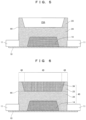
- FIG. 2 is a cross-sectional view showing the all-solid state secondary cell according to Embodiment 2 of the present invention.
- FIG. 3 is a cross-sectional view showing the production method of the all-solid state secondary cell according to Embodiment 1 of the present invention, and shows a step of bonding the insulating member to the positive electrode collector.
- FIG. 4 is a cross-sectional view showing the same production method, and shows a step of disposing the positive electrode powder layer.
- FIG. 5 is a cross-sectional view showing the same production method, and shows a step of disposing the solid electrolyte layer.
- FIG. 6 is a cross-sectional view showing the same production method, and shows a step of disposing the negative electrode powder layer.
- FIG. 7 is a cross-sectional view showing the same production method, and shows a step of disposing the negative electrode collector.
- FIG. 8 is a cross-sectional view showing the same production method, and shows a step of pressing.
- FIG. 9 is a cross-sectional view showing the production method of the all-solid state secondary cell according to Embodiment 2 of the present invention, and shows a step of disposing the negative electrode collector.
- FIG. 10 is a cross-sectional view showing the same production method, and shows a step of pressing.
- FIG. 11 is a perspective view except the negative electrode collector and the insulating member of the all-solid state secondary cell according to Example 1 of the present invention.
- FIG. 12 is a cross-sectional view showing the same all-solid state secondary cell.
- FIG. 13 is a perspective view except the negative electrode collector and the insulating member of the all-solid state secondary cell according to Example 2 of the present invention.
- FIG. 14 is a plan view showing the same all-solid state secondary cell.
- FIG. 15 is a cross-sectional view showing A-A of FIG. 14 , wherein the left side shows the cross section which passes along a corner part, and the right side shows cross section which passes along an edge part.
- FIG. 16 is a cross-sectional view showing the production method of the all-solid state secondary cell according to Embodiment 3 of the present invention, and shows a step of disposing the negative electrode collector.
- FIG. 17 is a cross-sectional view showing the same production method, and shows a step of pressing.
- FIG. 18 is a cross-sectional view showing the same production method in case that the all-solid state secondary cell has a thicker center part than a peripheral edge part, and shows a step of pressing.
- FIG. 19 is a cross-sectional view showing the all-solid state secondary cell according to Example 3 of the present invention.
- FIG. 20 is a sectional view showing the all-solid state secondary cell according to Example 4 of the present invention.
- FIG. 21 is a cross-sectional view showing the all-solid state secondary cell according to Example 5 of the present invention.
- this all-solid state secondary cell includes the positive electrode collector and the negative electrode collector 30 , and the powder laminate 40 disposed between the positive electrode collector 10 and the negative electrode collector 30 .
- This powder laminate 40 has the positive electrode powder layer 14 disposed on the side of the positive electrode collector 10 ; the negative electrode powder layer 34 disposed on the side of the negative electrode collector 30 ; the solid electrolyte layer 24 disposed between the positive electrode powder layer 14 and the negative electrode powder layer 34 and covering the outer periphery of the positive electrode powder layer 14 ; and the outer peripheral powder layer 23 disposed on the outer periphery of the negative electrode powder layer 34 .
- the positive electrode powder layer 14 , the positive electrode collector 10 , the negative electrode powder layer 34 , and the negative electrode collector 30 are not limited to the positional relationship shown in FIGS. 1 and 2 .
- the positional relationships shown in FIGS. 1 and 2 may be interchanged, that is, the reference numerals 14 and 10 may be the negative electrode powder layer and the negative electrode collector, and the reference numerals 34 and 30 may be the positive electrode powder layer and the positive electrode collector.
- the solid electrolyte layer 24 covers not the outer periphery of the positive electrode powder layer 14 as shown in FIGS.
- the above outer peripheral powder layer 23 may be composed of any powder such as the same powder as the solid electrolyte layer 24 or a powder that suppresses the generation of hydrogen sulfide (a powder that adsorbs hydrogen sulfide).
- the above outer peripheral powder layer 23 is a part (upper part) of the solid electrolyte layer when composed of the same powder as the solid electrolyte layer 24 .
- parts indicated by reference numeral 24 are a lower part and middle part of the solid electrolyte layer.
- the above outer peripheral powder layer 23 is a hydrogen sulfide adsorption layer when composed of a powder that adsorbs hydrogen sulfide; a moisture adsorption layer when composed of powder that adsorbs moisture; and a hydrogen sulfide adsorption layer and moisture adsorption layer when composed of a powder that adsorbs both hydrogen sulfide and moisture.
- this powder constituting the hydrogen sulfide adsorption layer and the moisture adsorption layer include porous materials such as zeolite, silica gel, or activated carbon.
- the above powder laminate 40 is composed of a powder without gaps, that is, densely composed of a powder.
- the outer side surface 44 of the above powder laminate 40 does not include the contact part between the above powder laminate 40 and the insulating member 11 (not an essential component) disposed by inserting from the outer periphery of the powder laminate 40 .
- the above powder laminate 40 consists of the peripheral edge part 46 including the above outer side surface 44 and the center part 49 surrounded by the peripheral edge part 46 .
- the thickness of this peripheral edge part 46 is equal to or greater than the thickness of the center part 49 .
- the thickness of the above peripheral edge part 46 may be equal to the thickness of the center part 49 as shown in FIG. 1
- the thickness of the above peripheral edge part 46 may exceed the thickness of the center part 49 as shown in FIG. 2 .
- the all-solid state secondary cell 1 includes the positive electrode collector 10 and the negative electrode collector 30 ; the powder laminate 40 disposed between the positive electrode collector 10 and the negative electrode collector 30 ; and the insulating member 11 disposed by being bonded to the surface (upper surface) of the positive electrode collector 10 and inserted from the outer periphery of the powder laminate 40 thereinto.
- the above powder laminate 40 consists of the positive electrode powder layer 14 disposed on the side of the positive electrode collector 10 without contacting the insulating member 11 ; the negative electrode powder layer disposed on the side of the negative electrode collector 30 ; the lower part and middle part 24 of the solid electrolyte layer disposed between the positive electrode powder layer 14 and the negative electrode powder layer 34 and covering the outer periphery of the positive electrode powder layer 14 ; and the upper part 23 of the solid electrolyte layer disposed on the outer periphery of the above negative electrode powder layer 34 (an example of the outer peripheral powder layer 23 ).
- the above positive electrode collector 10 and the negative electrode collector 30 are pressed in a direction in which the collectors are brought close to each other in the production process, and thereby the above powder laminate 40 is composed of a powder without gaps, that is, densely composed of a powder.
- the outer side surface 44 of the above powder laminate 40 does not include the contact part between the above powder laminate 40 and the insulating member 11 (not an essential component).
- the above powder laminate 40 consists of the peripheral edge part 46 including the above outer side surface 44 and the center part 49 surrounded by the peripheral edge part 46 .
- the thickness of the above peripheral edge part 46 is approximately equal to the thickness of the center part 49 (an error in production is included).
- a thin plate and a foil consist of copper (Cu), magnesium (Mg), stainless steel, titanium (Ti), iron (Fe), cobalt (Co), nickel (Ni), zinc (Zn), aluminum (Al) germanium (Ge), indium (In), lithium (Li), tin (Sn), and their alloys, or a film formed from various materials.
- the thin plate and the foil have a thickness in the range of 5 ⁇ m to 100 ⁇ m.
- the positive electrode collector 10 and the negative electrode collector 30 preferably have their surfaces subjected to a roughening treatment, from the viewpoint of improving the adhesion with the powder laminate 40 composed of a powder.
- the roughening treatment is a treatment to increase the surface roughness by etching or the like.
- an insulating sheet made of a polymer material such as a PET film is used.
- the positive electrode powder layer 14 /the negative electrode powder layer 34 are layers consisting of materials mixed with positive electrode active material/negative electrode active material securing an electron conduction path between particles in order to exchange electrons and a solid electrolyte having ion conductivity at a predetermined ratio.
- the positive electrode active material/negative electrode active material are mixed with the solid electrolyte having lithium ion conductivity, thereby providing ion conductivity in addition to electron conductivity and allowing to secure the ion conduction path between particles.
- the positive electrode powder layer 14 /negative electrode powder layer 34 may be a layer consisting of only the positive electrode active material/negative electrode active material.
- the positive electrode active material suitable for the positive electrode powder layer 14 is not particularly limited as long as it can intercalate and deintercalate lithium ions.
- this positive electrode active material include oxides such as lithium-nickel composite oxide (LiNi x M 1-x O 2 ), lithium cobaltate (LiCoO 2 ), lithium nickelate (LiNiO 2 ), lithium-nickel-cobalt-aluminum composite oxide (LiNiO 0.8 Co 0.15 Al 0.05 O 2 , NCA layered oxide), lithium manganate (such as spinel lithium manganate LiMn 2 O 4 ), and Li-excess composite oxide (Li 2 MnO 3 —LiMO 2 ) and compounds other than oxides.
- oxides such as lithium-nickel composite oxide (LiNi x M 1-x O 2 ), lithium cobaltate (LiCoO 2 ), lithium nickelate (LiNiO 2 ), lithium-nickel-cobalt-aluminum composite oxide (LiNiO 0.8
- Examples of compounds other than oxides include olivine compounds (LiMPO 4 ), sulfur-containing compounds (such as Li 2 S), and the like.
- M represents a transition metal.
- the positive electrode active material can be used alone or in combination of two or more materials. From the viewpoint of easily obtaining a high capacity, a lithium-containing oxide including at least one selected from the group consisting of Co, Ni, and Mn is preferable.
- the lithium-containing oxide may further include a typical metal element such as Al.
- the surface of the above positive electrode active material may be coated with a coating material, from the viewpoint of improving rate properties.
- a coating material include Li 4 Ti 5 O 12 , LiTaO 3 , Li 4 NbO 3 , LiAlO 2 , Li 2 ZrO 3 , Li 2 WO 4 , Li 2 TiO 3 , Li 2 B 4 O 7 , Li 3 PO 4 , Li 2 MoO 4 , LiBO 2 , alumina (Al 2 O 3 ), or carbon (C).
- the negative electrode active material suitable for the negative electrode powder layer 34 the material mixed with the negative electrode active material and the lithium ion conductive solid electrolyte is used, or the negative electrode active material is used alone.
- the negative electrode active material is not particularly limited as long as lithium ions can be intercalated and deintercalated, and known negative electrode active materials used in all-solid cells can be used.
- Examples of the negative electrode active material include carbonaceous materials capable of intercalating and deintercalating lithium ions, and simple substances of metals or semimetals, alloys, compounds, and the like capable of intercalating and deintercalating lithium ions.
- Examples of the carbonaceous material include graphite (such as natural graphite and artificial graphite), hard carbon, amorphous carbon, and the like.
- Examples of simple substances of metals or semimetals and alloys include lithium metals or alloys, a simple substance of Si, and the like.
- Examples of the compound include oxides, sulfides, nitrides, hydrates, silicides (such as lithium silicide), and the like.
- Examples of the oxide include titanium oxide and silicon oxide.
- the negative electrode active material may be used alone or in combination of two or more.
- silicon oxide and carbonaceous material may be used in combination.
- coated particles including graphite particles and amorphous carbon coating the graphite particles are more preferable.
- the solid electrolyte is roughly classified into an organic polymer electrolyte (also referred to as an organic solid electrolyte), an inorganic solid electrolyte, and the like, but any of these solid electrolytes may be used.
- the inorganic solid electrolyte is roughly classified into an oxide-based material and sulfide-based material, and any of these materials may be used.
- the inorganic solid electrolyte can be appropriately selected from crystalline or amorphous ones. That is, the solid electrolyte can be appropriately selected from materials consisting of an organic compound, an inorganic compound, or a mixture thereof.
- materials capable of being used as the solid electrolyte include a lithium ion conductive solid electrolyte or a sulfide inorganic solid electrolyte known to have higher ion conductivity than other inorganic compounds.
- Other examples of the material capable of being used as a solid electrolyte include a lithium-containing metal oxide (one or more metals) such as Li 2 —SiO 2 and Li 2 —SiO 2 —P 2 O 5 ; a lithium-containing metal nitride such as Li x P y O 1-z N 2 ; a lithium-containing sulfide glass such as Li 2 S—P 2 S 5 system, Li 2 S—SiS 2 system, Li 2 S—B 2 S 3 system, Li 2 S—GeS 2 system, Li 2 S—SiS 2 —LiI system, Li 2 S—SiS 2 —Li 3 PO 4 system, Li 2 S—Ge 2 S 2 system, Li 2 S—GeS 2 —P 2 S
- a sulfide (sulfide inorganic solid electrolyte) is preferable.
- the sulfide include Li 2 S and one or more sulfides including at least one element selected from the group consisting of group 13 elements, group 14 elements, and group 15 elements of the periodic table.
- the group 13 to 15 elements of the periodic table are not particularly limited, but examples thereof include P, Si, Ge, As, Sb, Al, or the like, and P, Si, and Ge are preferable, and P is particularly preferably.
- the sulfide including these elements (particularly, P) and Li are also preferable.
- the solid electrolyte suitable for the solid electrolyte layers 23 and 24 may be the same as or different from the solid electrolyte used in the positive electrode powder layer 14 and the negative electrode powder layer 34 .
- the positive electrode active material, the negative electrode active material, and the solid electrolyte are not limited to the above materials, and materials generally used in the field of cells can also be used.
- the insulating member 11 in which the opening part 11 A is formed is bonded to the surface of the positive electrode collector 10 .
- the opening part 11 A of the insulating member 11 is a space in which the powder laminate 40 is disposed, and is inserted from the outer periphery of the powder laminate 40 , and has the size such that the opening part 11 A is not contact with the positive electrode powder layer 14 of the powder laminate 40 .
- the positive electrode powder layer 14 is disposed in the opening part 11 A of the insulating member 11 . Since the positive electrode powder layer 14 is later pressed in the thickness direction, the positive electrode powder layer 14 is shaped in consideration of the deformation due to the pressing.
- the solid electrolyte layers 23 and 24 are disposed on the insulating member 11 and the positive electrode powder layer 14 disposed in the opening part 11 A of the insulating member 11 .
- the disposing the solid electrolyte layers 23 and 24 is divided into two steps.
- These two steps consist of: disposing the lower part and middle part 24 of the solid electrolyte layer on the surface (upper surface) of the insulating member 11 so as to bury the positive electrode powder layer 14 disposed in the opening part 11 A of the insulating member 11 ; and disposing the upper part 23 of the solid electrolyte layer on the surface (upper surface) of the middle part 24 of the solid electrolyte layer so as to cover the space part 23 A and the outer periphery of the space part 23 A.
- one step may be used, that is, the solid electrolyte layers 23 and 24 may be disposed while the thicknesses of the solid electrolyte layers 23 and 24 are different.
- a specific example of the one step includes using of the openings of the screen different between the peripheral edge part 46 and the center part 49 in order to make the thickness of the formed layer different in the film formation by the electrostatic method.
- the negative electrode powder layer 34 is disposed in the space part 23 A, the outer periphery of which is covered by the upper part 23 of the solid electrolyte layer.
- the powder laminate 40 is formed by disposing the negative electrode powder layer 34 .
- the powder laminate 40 consists of the peripheral edge part 46 including the outer side surface and the center part 49 surrounded by the peripheral edge part 46 .
- the thickness of the peripheral edge part 46 is substantially equal to the thickness of the center part (an error in production is included).
- the surface of the upper part 23 of the solid electrolyte layer and the surface of the negative electrode powder layer 34 are substantially flat (an error in production is included).
- the negative electrode collector 30 is disposed on the surface of the upper part 23 of the solid electrolyte layer and on the surface of the negative electrode powder layer 34 which are substantially flat.
- the positive electrode collector 10 and the negative electrode collector 30 are pressed with a high pressure of several hundred MPa or greater in the direction in which the collectors are brought close to each other. Due to this pressing, the powder laminate 40 becomes thinner and spreads in the direction orthogonal to the thickness direction, and the powder laminate 40 is composed of powder without gaps, that is, the powder laminate 40 is densely made of powder.
- the above pressing provides the all-solid state secondary cell 1 as shown in FIG. 1 .
- the outer peripheries of the positive electrode powder layer 14 and the negative electrode powder layer 34 are covered by the solid electrolyte layers 23 and 24 , and the thickness of the peripheral edge part 46 is equal to the thickness of the center part 49 , allowing to prevent a short circuit between the positive and negative electrodes.
- the positive electrode powder layer 14 and the negative electrode powder layer 34 are electrically isolated sufficiently to prevent a short circuit between the positive and negative electrodes, and cell performance can be further improved.
- the thickness of the peripheral edge part 46 is greater than that of the center part 49 .
- the all-solid state secondary cell according to Embodiment 2 of the present invention is hard to be collapsed by increasing the thickness of the peripheral edge part 46 , which is a relatively collapsible part, over the center part 49 , which is a part being relatively hard to be collapsed.
- the upper part 23 of the solid electrolyte layer according to Embodiment 2 of the present invention is disposed to be higher than the upper surface of the negative electrode powder layer 34 disposed thereafter (or already disposed).
- the negative electrode powder layer 34 according to Embodiment 2 of the present invention is disposed to be lower than the upper surface of the upper part 23 of the solid electrolyte layer already disposed (or disposed thereafter). That is, the upper part 23 of the solid electrolyte layer and the negative electrode powder layer 34 are disposed such that the thickness of the peripheral edge part 46 is greater than the thickness of the center part 49 .
- the negative electrode collector 30 is disposed on the surface of the upper part 23 of the solid electrolyte layer and on the surface of the negative electrode powder layer 34 .
- the positive electrode collector 10 and the negative electrode collector 30 are pressed by an elastic body having a flat press surface with a high pressure of several hundred MPa or greater in the direction in which the collectors are brought close to each other. Due to this pressing, the powder laminate becomes thinner and spreads in the direction orthogonal to the thickness direction, and the powder laminate 40 is composed of powder without gaps, that is, the powder laminate 40 is densely composed of powder.
- the relatively thick peripheral edge part 46 and the relatively thin center part 49 are pressed by the elastic body having a flat press surface via the negative electrode collector 30 . The thicker peripheral edge part 46 is pressed more tightly than the thinner center part 49 , and is compacted more tightly.
- peripheral edge part 46 is secured to be hard to be collapsed not only due to being thicker than the center part 49 , but also due to being compacted more tightly than the center part 49 .
- the peripheral edge part 46 is as hard to be collapsed as the center part 49 or is harder to be collapsed than the center part 49 .
- Embodiment 1 According to the all-solid state secondary cell 1 according to Embodiment 2 of the present invention and the production method of the same, there are the effects in Embodiment 1 and the peripheral edge part 46 which is a collapsible part becomes harder to be collapsed, allowing to further prevent a short circuit between the positive and negative electrodes.
- the powder laminate 40 was made to be a perfect circle in a plan view.
- the negative electrode collector 30 and the insulating member are omitted in order to make the surface of the powder laminate 40 more visible.
- the all-solid state secondary cell 1 according to the present Example 1 has two insulating members 11 and 12 as shown in FIG. 12 . These two insulating members 11 and 12 are composed of the first insulating member 11 which is the same as the insulating member 11 in the above Embodiment 2, and the second insulating member 12 positioned above this first insulating member 11 .
- the second insulating member 12 is disposed in contact with the boundary between the upper part 23 and the middle part 24 of the solid electrolyte layer on the outer side surface 44 of the powder laminate 40 .
- the above all-solid state secondary cell 1 has the first adhesive layer 51 disposed between the first insulating member 11 and the second insulating member 12 ; and the second adhesive layer 52 disposed between the second insulating member 12 and the negative electrode collector 30 .
- the positive electrode collector 10 etched aluminum with a thickness of 20 ⁇ m was used.
- the positive electrode powder layer 14 a mixture of the positive electrode active material and the lithium ion conductive solid electrolyte at a weight ratio of 7:3 was used.
- the above positive electrode active material was LiNi 0.8 Co 0.15 Al 0.05 O 2
- the lithium ion conductive solid electrolyte was Li 2 S (70 mol %)-P 2 S 5 (30 mol %).
- the positive electrode powder layer 14 was formed into a film on the positive electrode collector 10 by charging due to corona discharge of that powder material and spraying with an inert gas, and disposed so as to have ⁇ 50 mm and a thickness of 100 ⁇ m after pressing.
- the solid electrolyte layer 24 Li 2 S (70 mol %)-P 2 S 5 (30 mol %) was used.
- the lower part and middle part 24 of the solid electrolyte layer were disposed so as to have ⁇ 54 mm and a thickness of 75 ⁇ m after pressing. Thereafter, the upper part 23 of the solid electrolyte layer was disposed only at the part of ⁇ 54 to 52 (the space part 23 A at less than ⁇ 52), and at the thickness of 150 ⁇ m after pressing.
- the negative electrode powder layer 34 As the negative electrode powder layer 34 , a mixture of the negative electrode active material and the lithium ion conductive solid electrolyte at a weight ratio of 6:4 was used.
- the negative electrode active material was graphite, and the lithium ion conductive solid electrolyte was (70 mol %)-P 2 S 5 (30 mol %).
- the negative electrode powder layer 34 was disposed so as to have ⁇ 52 mm and a thickness of 100 ⁇ m after pressing.
- the negative electrode collector 30 As the other hand, as the negative electrode collector 30 , a copper foil being subjected to roughening treatment and having a thickness of 18 ⁇ m was used.
- a double-sided adhesive tape was used as the first adhesive layer 51 and the second adhesive layer 52 .
- the all-solid state secondary cell according to Comparative Example 1 does not have a part corresponding to the upper part 23 of the solid electrolyte layer. For this reason, in the all-solid state secondary cell according to Comparative Example 1, the outer periphery of the negative electrode powder layer is not covered with the solid electrolyte layer.
- the powder laminate 40 was made to be a 100 mm square in a plan view.
- the negative electrode collector 30 and the insulating members 11 and 12 are omitted in order to make the surface of the powder laminate 40 more visible.
- the powder laminate 40 of the all-solid state secondary cell 1 according to the present Example 2 is square in plan view, and the peripheral edge part 46 thereof is composed of four corner parts 47 and four side parts 48 located between the adjacent corner parts 47 .
- the corner part 47 was thicker than the side part 48 and the center part 49 respectively, and the thicknesses of the side parts 48 and center part 49 were the same (an error in production was included).
- the upper part 23 of the solid electrolyte layer which had a thickness of 150 ⁇ m after pressing in the above Example 1, had a thickness of 250 ⁇ m after pressing in the corner part 47 of the present Example 2 (refer to left side in FIG. 15 ), and had a thickness of 100 ⁇ m after pressing in the side part 48 in the present Example 2 (refer to right side in FIG. 15 ).
- the present Example 2 is the same as the above Example 1 except for the contents described above.
- the all-solid state secondary cell according to the present Comparative Example 2 does not have a part corresponding to the upper part 23 of the solid electrolyte layer. For this reason, in the all-solid state secondary cell according to the present Comparative Example 2, the outer periphery of the negative electrode powder layer is not covered with the solid electrolyte layer.
- the success rate of charge and discharge was able to be also improved, in other words, a short circuit between positive and negative electrodes was able to be prevented.
- the insulating members 11 and 12 which are members disposed on the outer periphery outside the outer side surface 44 , the first adhesive layer 51 , and the second adhesive layer 52 were not described in detail due to unessential configuration.
- the positive electrode collector 10 and the negative electrode collector 30 are considered not to be deformed even when pressed in a direction in which the collectors are brought close to each other, the member disposed on the outer periphery outside the outer side surface 44 (hereinafter, referred to as outer peripheral member) also an important configuration.
- the positive electrode collector 10 and the negative electrode collector 30 which are relatively thin and weak members may be deformed due to bending or the like at the outer side surface 44 .
- the positive electrode collector 10 and the negative electrode collector 30 are thin and weak members such as aluminum or etched aluminum having a thickness of 30 ⁇ m or less, the above deformation becomes remarkable.
- the outer peripheral member is a member other than the positive electrode collector 10 and the negative electrode collector 30 and disposed on the outer periphery outside the outer side surface 44 , and hence corresponds to the insulating member 11 in Embodiment 3 as shown in FIG. 16 and FIG. 17 .
- the positive electrode collector 10 and the negative electrode collector 30 are pressed in a direction in which the collectors are brought close to each other, so that the pressure ⁇ 1 generated in the powder laminate 40 and the pressure ⁇ 2 generated in the insulating member 11 which is the outer peripheral member 50 are equal.
- Such pressing is easily achieved by the following method. Specifically, as shown in FIG. 16 , before the positive electrode collector 10 and the negative electrode collector 30 are pressed in the direction in which the collectors are brought close to each other, the thickness of the powder laminate 40 is greater than the thickness of the insulating member 11 which is the outer peripheral member 50 disposed on the outer periphery outside the outer side surface 44 .
- the positive electrode collector 10 and the negative electrode collector 30 are pressed in a direction in which the collectors are brought close to each other.
- the thickness of the above powder laminate 40 before the above pressing is defined as T1
- the thickness of the above outer peripheral member 50 before the above pressing as T2 the modulus of elasticity of the above outer peripheral member 50 as E2
- T ′ (1 ⁇ 1)
- T 1 (1 ⁇ 2) T 2 (2)
- T1 is the thickness of the thickest part of the above powder laminate 40 before the above pressing
- T′ is the equal thicknesses of the thickest part of the powder laminate 40 and the peripheral member 50 due to the above pressing.
- the thickness of the first insulating member 11 is equal to the thickness of the second insulating member 12 , and the thickness of the first adhesive layer 51 is greater than the thickness of the second adhesive layer 52 .
- Each of the thicknesses of the first insulating member 11 and the second insulating member 12 is smaller than the thickness of the positive electrode powder layer 14 , and the first adhesive layer 51 is disposed at the height of the boundary between the middle part 24 and the upper part 23 of the solid electrolyte layer.
- the thickness of the first insulating member 11 is greater than the thickness of the second insulating member 12 , and the thickness of the first adhesive layer 51 is greater than the thickness of the second adhesive layer 52 .
- the thickness of the first insulating member 11 is equal to the thickness of the lower part and middle part 24 of the solid electrolyte layer.
- the thickness of the second insulating member 12 is smaller than the thickness of the positive electrode powder layer 14 .
- the thickness of the first insulating member 11 and the thickness of the second insulating member 12 according to the above Example 4 are interchanged, and other than that is the same as the above Example 4.
- the pressure ⁇ 1 generated in the powder laminate 40 and the pressure ⁇ 2 generated in the outer peripheral member 50 become equal due to the above pressing. For this reason, even when the positive electrode collector 10 and the negative electrode collector 30 are relatively thin and weak members, these collectors are not deformed by the above pressing, and hence a short circuit between positive and negative electrodes can be suppressed.
- the upper part 23 of the solid electrolyte layer has been described as the outer peripheral powder layer 23 , and may be the hydrogen sulfide adsorption layer and/or the moisture adsorption layer.
- the hydrogen sulfide adsorption layer instead of the outer peripheral powder layer 23 adsorbs the dangerous hydrogen sulfide generated when the powder laminate 40 is collapsed, and hence safety can be improved.
- the moisture adsorption layer instead of the outer peripheral powder layer 23 adsorbs the moisture generated by long-term use, and hence degradation of cell performance due to long-term use can be suppressed.
- the hydrogen sulfide adsorption layer and the moisture adsorption layer instead of the outer peripheral powder layer 23 can improve the safety and can suppress the degradation of the cell performance due to long-term use. Even when the outer peripheral powder layer 23 is the hydrogen sulfide adsorption layer and/or the moisture adsorption layer, the thickness of the peripheral edge part 46 is equal to or greater than the thickness of the center part 49 , ensuring the effect that a short circuit between the positive and negative electrodes can be prevented.
- the negative electrode powder layer 34 is disposed after the upper part 23 of the solid electrolyte layer is disposed, but the upper part 23 of the solid electrolyte layer may be disposed after the negative electrode powder layer 34 is disposed.
- the positive electrode powder layer 14 and the positive electrode collector 10 , and the negative electrode powder layer 34 and the negative electrode collector 30 have the positional relationship as illustrated, but this positional relationship may be exchanged.
- the all-solid state secondary cell 1 includes the powder laminate 40 having a perfect circular shape and a square shape in plan view, but the shape of the powder laminate 40 is not limited to these shapes and may be an ellipse, a rectangle, another polygon, or the like in plan view. From the viewpoint of improving the cell performance, it is preferable that the powder laminate 40 has a circular shape (a perfect circle, an elliptical shape, an oval shape, an egg shape, or the like) without the corner part 47 which is a collapsible part.
Landscapes
- Chemical & Material Sciences (AREA)
- Chemical Kinetics & Catalysis (AREA)
- General Chemical & Material Sciences (AREA)
- Electrochemistry (AREA)
- Engineering & Computer Science (AREA)
- Manufacturing & Machinery (AREA)
- Inorganic Chemistry (AREA)
- Physics & Mathematics (AREA)
- General Physics & Mathematics (AREA)
- Condensed Matter Physics & Semiconductors (AREA)
- Dispersion Chemistry (AREA)
- Materials Engineering (AREA)
- Secondary Cells (AREA)
Abstract
Description
(E1/T1−E2/T2)T′=E1−E2 (1)
where T1 is a thickness of the powder laminate before the pressing, E1 is a modulus of elasticity of the powder laminate, T2 is a thickness of the outer peripheral member before the pressing, E2 is a modulus of elasticity of the outer peripheral member, and T′ is a thickness of the powder laminate to be made equal to the thickness of the outer peripheral member by the pressing.
(E1/T1−E2/T2)T′=E1−E2 (1)
T′=(1−ε1)T1=(1−ε2)T2 (2)
Claims (16)
(E1/T1−E2/T2)T′=E1−E2 (1)
Applications Claiming Priority (3)
| Application Number | Priority Date | Filing Date | Title |
|---|---|---|---|
| JP2016243870 | 2016-12-16 | ||
| JP2016-243870 | 2016-12-16 | ||
| PCT/JP2017/045048 WO2018110688A1 (en) | 2016-12-16 | 2017-12-15 | All-solid state secondary cell and production method for same |
Related Parent Applications (1)
| Application Number | Title | Priority Date | Filing Date |
|---|---|---|---|
| PCT/JP2017/045048 A-371-Of-International WO2018110688A1 (en) | 2016-12-16 | 2017-12-15 | All-solid state secondary cell and production method for same |
Related Child Applications (1)
| Application Number | Title | Priority Date | Filing Date |
|---|---|---|---|
| US18/240,090 Continuation US20230411702A1 (en) | 2016-12-16 | 2023-08-30 | All-solid state secondary cell and production method for same |
Publications (2)
| Publication Number | Publication Date |
|---|---|
| US20200076002A1 US20200076002A1 (en) | 2020-03-05 |
| US11784353B2 true US11784353B2 (en) | 2023-10-10 |
Family
ID=62558671
Family Applications (2)
| Application Number | Title | Priority Date | Filing Date |
|---|---|---|---|
| US16/468,111 Active 2038-08-20 US11784353B2 (en) | 2016-12-16 | 2017-12-15 | All-solid state secondary cell and production method for the same |
| US18/240,090 Pending US20230411702A1 (en) | 2016-12-16 | 2023-08-30 | All-solid state secondary cell and production method for same |
Family Applications After (1)
| Application Number | Title | Priority Date | Filing Date |
|---|---|---|---|
| US18/240,090 Pending US20230411702A1 (en) | 2016-12-16 | 2023-08-30 | All-solid state secondary cell and production method for same |
Country Status (6)
| Country | Link |
|---|---|
| US (2) | US11784353B2 (en) |
| EP (1) | EP3557685B1 (en) |
| JP (2) | JP6944953B2 (en) |
| KR (1) | KR102508381B1 (en) |
| CN (1) | CN110073539B (en) |
| WO (1) | WO2018110688A1 (en) |
Families Citing this family (22)
| Publication number | Priority date | Publication date | Assignee | Title |
|---|---|---|---|---|
| US11005104B2 (en) * | 2018-05-28 | 2021-05-11 | Panasonic Intellectual Property Management Co., Ltd. | Battery |
| JPWO2020013295A1 (en) * | 2018-07-13 | 2021-07-15 | 日立造船株式会社 | All-solid-state secondary battery manufacturing equipment |
| JP7182159B2 (en) * | 2018-12-12 | 2022-12-02 | パナソニックIpマネジメント株式会社 | All-solid battery |
| JP7052710B2 (en) * | 2018-12-26 | 2022-04-12 | トヨタ自動車株式会社 | Laminate |
| JP7276689B2 (en) * | 2019-10-02 | 2023-05-18 | トヨタ自動車株式会社 | Laminated battery and manufacturing method thereof |
| CN114747063A (en) * | 2019-12-04 | 2022-07-12 | 株式会社村田制作所 | Solid-state battery |
| JP7523310B2 (en) * | 2020-10-08 | 2024-07-26 | 日産自動車株式会社 | All-solid-state secondary battery, all-solid-state secondary battery system control method and all-solid-state secondary battery system control device |
| JP7243704B2 (en) * | 2020-11-30 | 2023-03-22 | トヨタ自動車株式会社 | All-solid secondary battery |
| JP7666008B2 (en) * | 2021-02-18 | 2025-04-22 | 日産自動車株式会社 | Lithium secondary battery |
| JP7542469B2 (en) * | 2021-03-19 | 2024-08-30 | 株式会社東芝 | Secondary battery, battery pack, and vehicle |
| JP7782143B2 (en) * | 2021-05-24 | 2025-12-09 | 日産自動車株式会社 | All solid state battery |
| JP7778525B2 (en) * | 2021-10-22 | 2025-12-02 | 日産自動車株式会社 | All solid state battery |
| CN119968732A (en) * | 2022-10-12 | 2025-05-09 | 大日本印刷株式会社 | All-solid-state battery |
| WO2024214202A1 (en) * | 2023-04-12 | 2024-10-17 | 日産自動車株式会社 | Lithium secondary battery |
| WO2025078850A1 (en) * | 2023-10-10 | 2025-04-17 | 日産自動車株式会社 | All-solid-state battery |
| KR20250071435A (en) * | 2023-11-15 | 2025-05-22 | 주식회사 엘지에너지솔루션 | All-solid-state battery and method for preparing the same |
| KR20250079255A (en) * | 2023-11-27 | 2025-06-04 | 주식회사 엘지에너지솔루션 | All-solid-state battery and method for preparing the same |
| CN120453278A (en) * | 2024-02-07 | 2025-08-08 | 宁德时代新能源科技股份有限公司 | Positive electrode sheet, all-solid-state battery, power-consuming device and preparation method |
| JP2025142617A (en) * | 2024-03-18 | 2025-10-01 | 本田技研工業株式会社 | solid state battery |
| JP7746442B1 (en) | 2024-03-18 | 2025-09-30 | 本田技研工業株式会社 | solid state battery |
| JP2025146158A (en) * | 2024-03-22 | 2025-10-03 | カナデビア株式会社 | Battery manufacturing apparatus and battery manufacturing method |
| KR20250167295A (en) * | 2024-05-22 | 2025-12-01 | 삼성에스디아이 주식회사 | Elastic sheet for all solid-state battery and all solid-state battery including the same |
Citations (20)
| Publication number | Priority date | Publication date | Assignee | Title |
|---|---|---|---|---|
| JPS62165880A (en) | 1986-01-17 | 1987-07-22 | Matsushita Electric Ind Co Ltd | Solid-electrolyte secondary cell |
| JP2001160413A (en) | 1999-12-06 | 2001-06-12 | Sony Corp | Battery manufacturing method |
| US20090017371A1 (en) | 2006-11-15 | 2009-01-15 | Yoshiyuki Nakamura | Power Storage Device |
| CN101517810A (en) | 2006-11-02 | 2009-08-26 | 丰田自动车株式会社 | Electricity storage device |
| CN101569030A (en) | 2006-12-21 | 2009-10-28 | 丰田自动车株式会社 | Electrical storage device |
| JP2011096550A (en) | 2009-10-30 | 2011-05-12 | Toyota Motor Corp | Solid battery, and manufacturing method of solid battery |
| JP2011124084A (en) | 2009-12-10 | 2011-06-23 | Toyota Motor Corp | All-solid-state battery |
| JP2013054949A (en) | 2011-09-05 | 2013-03-21 | Sumitomo Electric Ind Ltd | Nonaqueous electrolyte battery |
| CN103050647A (en) | 2011-10-17 | 2013-04-17 | 索尼公司 | Battery, method of manufacturing battery, battery pack, electronic device, electric vehicle, capacitive storage device, and power system |
| CN103190015A (en) | 2010-09-03 | 2013-07-03 | 日本电气株式会社 | Non-aqueous secondary battery and method for manufacturing non-aqueous secondary battery |
| US20130212875A1 (en) * | 2010-10-27 | 2013-08-22 | Koji Takahata | Method for producing lithium ion secondary battery |
| JP2013243004A (en) | 2012-05-18 | 2013-12-05 | Toyota Motor Corp | Solid battery, and solid battery manufacturing method |
| US20130344357A1 (en) * | 2011-03-17 | 2013-12-26 | Toyota Jidosha Kabushiki Kaisha | Solid battery and method for manufacturing solid battery |
| JP2014127463A (en) | 2012-12-27 | 2014-07-07 | Toyota Motor Corp | Method for manufacturing all solid state battery |
| JP2014222564A (en) * | 2013-05-13 | 2014-11-27 | 日立造船株式会社 | All-solid battery, manufacturing method of all-solid battery and manufacturing device for all-solid battery |
| JP2016018704A (en) | 2014-07-09 | 2016-02-01 | トヨタ自動車株式会社 | All-solid battery |
| JP2016192265A (en) | 2015-03-31 | 2016-11-10 | 日立造船株式会社 | Manufacturing method of all-solid-state secondary battery |
| WO2016208271A1 (en) | 2015-06-23 | 2016-12-29 | 日立造船株式会社 | All-solid-state secondary battery and production method therefor |
| US20170207465A1 (en) * | 2016-01-15 | 2017-07-20 | Fdk Corporation | Laminate-type power storage element and card electronic device |
| EP3451435A1 (en) | 2016-04-26 | 2019-03-06 | Hitachi Zosen Corporation | All-solid-state secondary battery |
-
2017
- 2017-12-15 JP JP2018556757A patent/JP6944953B2/en active Active
- 2017-12-15 KR KR1020197019848A patent/KR102508381B1/en active Active
- 2017-12-15 WO PCT/JP2017/045048 patent/WO2018110688A1/en not_active Ceased
- 2017-12-15 EP EP17880551.1A patent/EP3557685B1/en active Active
- 2017-12-15 CN CN201780077625.XA patent/CN110073539B/en active Active
- 2017-12-15 US US16/468,111 patent/US11784353B2/en active Active
-
2021
- 2021-08-30 JP JP2021139489A patent/JP7162109B2/en active Active
-
2023
- 2023-08-30 US US18/240,090 patent/US20230411702A1/en active Pending
Patent Citations (27)
| Publication number | Priority date | Publication date | Assignee | Title |
|---|---|---|---|---|
| JPS62165880A (en) | 1986-01-17 | 1987-07-22 | Matsushita Electric Ind Co Ltd | Solid-electrolyte secondary cell |
| JP2001160413A (en) | 1999-12-06 | 2001-06-12 | Sony Corp | Battery manufacturing method |
| CN101517810A (en) | 2006-11-02 | 2009-08-26 | 丰田自动车株式会社 | Electricity storage device |
| US20090269665A1 (en) | 2006-11-02 | 2009-10-29 | Yoshiyuki Nakamura | Power Storage Device |
| CN101461086A (en) | 2006-11-15 | 2009-06-17 | 丰田自动车株式会社 | Electricity storage device |
| US20090017371A1 (en) | 2006-11-15 | 2009-01-15 | Yoshiyuki Nakamura | Power Storage Device |
| CN101569030A (en) | 2006-12-21 | 2009-10-28 | 丰田自动车株式会社 | Electrical storage device |
| US20100035157A1 (en) | 2006-12-21 | 2010-02-11 | Toyota Jidosha Kabushiki Kaisha | Electrical storage device |
| JP2011096550A (en) | 2009-10-30 | 2011-05-12 | Toyota Motor Corp | Solid battery, and manufacturing method of solid battery |
| JP2011124084A (en) | 2009-12-10 | 2011-06-23 | Toyota Motor Corp | All-solid-state battery |
| CN103190015A (en) | 2010-09-03 | 2013-07-03 | 日本电气株式会社 | Non-aqueous secondary battery and method for manufacturing non-aqueous secondary battery |
| US20130209878A1 (en) | 2010-09-03 | 2013-08-15 | Nec Corporation | Nonaqueous secondary cell and method of manufacturing the same |
| US20130212875A1 (en) * | 2010-10-27 | 2013-08-22 | Koji Takahata | Method for producing lithium ion secondary battery |
| US20130344357A1 (en) * | 2011-03-17 | 2013-12-26 | Toyota Jidosha Kabushiki Kaisha | Solid battery and method for manufacturing solid battery |
| JP2013054949A (en) | 2011-09-05 | 2013-03-21 | Sumitomo Electric Ind Ltd | Nonaqueous electrolyte battery |
| US20130093398A1 (en) | 2011-10-17 | 2013-04-18 | Sony Corporation | Battery, method of manufacturing battery, battery pack, electronic device, electric vehicle, capacitive storage device, and power system |
| CN103050647A (en) | 2011-10-17 | 2013-04-17 | 索尼公司 | Battery, method of manufacturing battery, battery pack, electronic device, electric vehicle, capacitive storage device, and power system |
| JP2013243004A (en) | 2012-05-18 | 2013-12-05 | Toyota Motor Corp | Solid battery, and solid battery manufacturing method |
| JP2014127463A (en) | 2012-12-27 | 2014-07-07 | Toyota Motor Corp | Method for manufacturing all solid state battery |
| JP2014222564A (en) * | 2013-05-13 | 2014-11-27 | 日立造船株式会社 | All-solid battery, manufacturing method of all-solid battery and manufacturing device for all-solid battery |
| JP2016018704A (en) | 2014-07-09 | 2016-02-01 | トヨタ自動車株式会社 | All-solid battery |
| JP2016192265A (en) | 2015-03-31 | 2016-11-10 | 日立造船株式会社 | Manufacturing method of all-solid-state secondary battery |
| WO2016208271A1 (en) | 2015-06-23 | 2016-12-29 | 日立造船株式会社 | All-solid-state secondary battery and production method therefor |
| EP3316382A1 (en) | 2015-06-23 | 2018-05-02 | Hitachi Zosen Corporation | All-solid-state secondary battery and production method therefor |
| US20180198169A1 (en) | 2015-06-23 | 2018-07-12 | Hitachi Zosen Corporation | All-solid-state secondary battery and method of producing the same |
| US20170207465A1 (en) * | 2016-01-15 | 2017-07-20 | Fdk Corporation | Laminate-type power storage element and card electronic device |
| EP3451435A1 (en) | 2016-04-26 | 2019-03-06 | Hitachi Zosen Corporation | All-solid-state secondary battery |
Non-Patent Citations (6)
| Title |
|---|
| Decision to Grant a Patent dated Sep. 20, 2022, issued in corresponding Japanese Patent Application No. 2021-139489 with English translation (5 pgs ). |
| Extended European Search Report dated Dec. 3, 2019 issued in corresponding European Patent Application No. 17880551.1. |
| First Office Action dated Sep. 24, 2021, issued in corresponding Chinese Patent Application No. 201780077625.X with English translation (15 pgs.). |
| International Search Report dated Feb. 6, 2018 issued in corresponding International Application No. PCT/JP2017/045048 with English translation. |
| Machine Translation of JP2014222564A. (Year: 2014). * |
| Request for the Submission of an Opinion dated Sep. 1, 2022, issued in corresponding Korean Patent Application No. 10-2019-7019848 with English translation (13 pgs). |
Also Published As
| Publication number | Publication date |
|---|---|
| EP3557685C0 (en) | 2024-04-10 |
| EP3557685A4 (en) | 2020-01-01 |
| US20230411702A1 (en) | 2023-12-21 |
| CN110073539A (en) | 2019-07-30 |
| KR102508381B1 (en) | 2023-03-08 |
| JPWO2018110688A1 (en) | 2019-10-24 |
| CN110073539B (en) | 2022-07-19 |
| JP6944953B2 (en) | 2021-10-06 |
| WO2018110688A1 (en) | 2018-06-21 |
| KR20190089071A (en) | 2019-07-29 |
| JP7162109B2 (en) | 2022-10-27 |
| US20200076002A1 (en) | 2020-03-05 |
| EP3557685A1 (en) | 2019-10-23 |
| JP2021182565A (en) | 2021-11-25 |
| EP3557685B1 (en) | 2024-04-10 |
Similar Documents
| Publication | Publication Date | Title |
|---|---|---|
| US20230411702A1 (en) | All-solid state secondary cell and production method for same | |
| CN110416629B (en) | All-solid-state battery | |
| EP3316382B1 (en) | All-solid-state secondary battery and production method therefor | |
| US11888158B2 (en) | Battery | |
| JP6576072B2 (en) | Manufacturing method of all-solid-state secondary battery | |
| JP7133316B2 (en) | All-solid secondary battery and manufacturing method thereof | |
| TW202422923A (en) | Cell assembly and all solid-state battery comprising the same | |
| KR20230009460A (en) | Battery and its manufacturing method | |
| JP2017183120A (en) | All-solid secondary battery and manufacturing method thereof | |
| US11302958B2 (en) | Method and apparatus for producing all-solid-state battery | |
| JP7182160B2 (en) | All-solid battery | |
| US20250132462A1 (en) | All-solid-state battery | |
| JP2008153015A (en) | Negative electrode and battery | |
| US20240120552A1 (en) | Sulfide Solid-State Battery, Printed Circuit Board with Sulfide Solid-State Battery, and Manufacturing Method of Sulfide Solid-State Battery | |
| KR20200070723A (en) | All-solid state batteery comprising an insulating member for short circuit protection and preparing method thereof | |
| WO2025216060A1 (en) | Mold, power generation element and manufacturing method therefor, and all-solid-state battery and manufacturing method therefor |
Legal Events
| Date | Code | Title | Description |
|---|---|---|---|
| FEPP | Fee payment procedure |
Free format text: ENTITY STATUS SET TO UNDISCOUNTED (ORIGINAL EVENT CODE: BIG.); ENTITY STATUS OF PATENT OWNER: LARGE ENTITY |
|
| AS | Assignment |
Owner name: HITACHI ZOSEN CORPORATION, JAPAN Free format text: ASSIGNMENT OF ASSIGNORS INTEREST;ASSIGNORS:OKAMOTO, KENJI;FUKUI, HIDEYUKI;REEL/FRAME:049885/0028 Effective date: 20190528 |
|
| STPP | Information on status: patent application and granting procedure in general |
Free format text: DOCKETED NEW CASE - READY FOR EXAMINATION |
|
| STPP | Information on status: patent application and granting procedure in general |
Free format text: NON FINAL ACTION MAILED |
|
| STPP | Information on status: patent application and granting procedure in general |
Free format text: RESPONSE TO NON-FINAL OFFICE ACTION ENTERED AND FORWARDED TO EXAMINER |
|
| STPP | Information on status: patent application and granting procedure in general |
Free format text: FINAL REJECTION MAILED |
|
| STPP | Information on status: patent application and granting procedure in general |
Free format text: DOCKETED NEW CASE - READY FOR EXAMINATION |
|
| STPP | Information on status: patent application and granting procedure in general |
Free format text: NON FINAL ACTION MAILED |
|
| STPP | Information on status: patent application and granting procedure in general |
Free format text: RESPONSE TO NON-FINAL OFFICE ACTION ENTERED AND FORWARDED TO EXAMINER |
|
| STPP | Information on status: patent application and granting procedure in general |
Free format text: NON FINAL ACTION MAILED |
|
| STPP | Information on status: patent application and granting procedure in general |
Free format text: NOTICE OF ALLOWANCE MAILED -- APPLICATION RECEIVED IN OFFICE OF PUBLICATIONS |
|
| STPP | Information on status: patent application and granting procedure in general |
Free format text: PUBLICATIONS -- ISSUE FEE PAYMENT VERIFIED |
|
| STCF | Information on status: patent grant |
Free format text: PATENTED CASE |