US11780754B2 - Return flow system for ion concentration polarization (ICP) desalination - Google Patents
Return flow system for ion concentration polarization (ICP) desalination Download PDFInfo
- Publication number
- US11780754B2 US11780754B2 US16/839,152 US202016839152A US11780754B2 US 11780754 B2 US11780754 B2 US 11780754B2 US 202016839152 A US202016839152 A US 202016839152A US 11780754 B2 US11780754 B2 US 11780754B2
- Authority
- US
- United States
- Prior art keywords
- stream
- channel
- outlet
- icp
- return flow
- Prior art date
- Legal status (The legal status is an assumption and is not a legal conclusion. Google has not performed a legal analysis and makes no representation as to the accuracy of the status listed.)
- Active, expires
Links
Images


Classifications
-
- C—CHEMISTRY; METALLURGY
- C02—TREATMENT OF WATER, WASTE WATER, SEWAGE, OR SLUDGE
- C02F—TREATMENT OF WATER, WASTE WATER, SEWAGE, OR SLUDGE
- C02F1/00—Treatment of water, waste water, or sewage
- C02F1/46—Treatment of water, waste water, or sewage by electrochemical methods
- C02F1/469—Treatment of water, waste water, or sewage by electrochemical methods by electrochemical separation, e.g. by electro-osmosis, electrodialysis, electrophoresis
- C02F1/4693—Treatment of water, waste water, or sewage by electrochemical methods by electrochemical separation, e.g. by electro-osmosis, electrodialysis, electrophoresis electrodialysis
- C02F1/4695—Treatment of water, waste water, or sewage by electrochemical methods by electrochemical separation, e.g. by electro-osmosis, electrodialysis, electrophoresis electrodialysis electrodeionisation
-
- C—CHEMISTRY; METALLURGY
- C02—TREATMENT OF WATER, WASTE WATER, SEWAGE, OR SLUDGE
- C02F—TREATMENT OF WATER, WASTE WATER, SEWAGE, OR SLUDGE
- C02F1/00—Treatment of water, waste water, or sewage
- C02F1/46—Treatment of water, waste water, or sewage by electrochemical methods
- C02F1/469—Treatment of water, waste water, or sewage by electrochemical methods by electrochemical separation, e.g. by electro-osmosis, electrodialysis, electrophoresis
- C02F1/4693—Treatment of water, waste water, or sewage by electrochemical methods by electrochemical separation, e.g. by electro-osmosis, electrodialysis, electrophoresis electrodialysis
-
- C—CHEMISTRY; METALLURGY
- C02—TREATMENT OF WATER, WASTE WATER, SEWAGE, OR SLUDGE
- C02F—TREATMENT OF WATER, WASTE WATER, SEWAGE, OR SLUDGE
- C02F2201/00—Apparatus for treatment of water, waste water or sewage
- C02F2201/46—Apparatus for electrochemical processes
-
- C—CHEMISTRY; METALLURGY
- C02—TREATMENT OF WATER, WASTE WATER, SEWAGE, OR SLUDGE
- C02F—TREATMENT OF WATER, WASTE WATER, SEWAGE, OR SLUDGE
- C02F2201/00—Apparatus for treatment of water, waste water or sewage
- C02F2201/46—Apparatus for electrochemical processes
- C02F2201/461—Electrolysis apparatus
- C02F2201/46105—Details relating to the electrolytic devices
- C02F2201/4611—Fluid flow
-
- C—CHEMISTRY; METALLURGY
- C02—TREATMENT OF WATER, WASTE WATER, SEWAGE, OR SLUDGE
- C02F—TREATMENT OF WATER, WASTE WATER, SEWAGE, OR SLUDGE
- C02F2201/00—Apparatus for treatment of water, waste water or sewage
- C02F2201/46—Apparatus for electrochemical processes
- C02F2201/461—Electrolysis apparatus
- C02F2201/46105—Details relating to the electrolytic devices
- C02F2201/46115—Electrolytic cell with membranes or diaphragms
-
- C—CHEMISTRY; METALLURGY
- C02—TREATMENT OF WATER, WASTE WATER, SEWAGE, OR SLUDGE
- C02F—TREATMENT OF WATER, WASTE WATER, SEWAGE, OR SLUDGE
- C02F2201/00—Apparatus for treatment of water, waste water or sewage
- C02F2201/46—Apparatus for electrochemical processes
- C02F2201/461—Electrolysis apparatus
- C02F2201/46105—Details relating to the electrolytic devices
- C02F2201/4618—Supplying or removing reactants or electrolyte
-
- Y—GENERAL TAGGING OF NEW TECHNOLOGICAL DEVELOPMENTS; GENERAL TAGGING OF CROSS-SECTIONAL TECHNOLOGIES SPANNING OVER SEVERAL SECTIONS OF THE IPC; TECHNICAL SUBJECTS COVERED BY FORMER USPC CROSS-REFERENCE ART COLLECTIONS [XRACs] AND DIGESTS
- Y02—TECHNOLOGIES OR APPLICATIONS FOR MITIGATION OR ADAPTATION AGAINST CLIMATE CHANGE
- Y02A—TECHNOLOGIES FOR ADAPTATION TO CLIMATE CHANGE
- Y02A20/00—Water conservation; Efficient water supply; Efficient water use
- Y02A20/124—Water desalination
Definitions
- ICP desalination and trifurcate ICP desalination systems have been described, for example, in U.S. Patent App. Pub. No. 2014/0374274 A1 (entitled “Water Desalination/Purification and Bio-Agent Preconcentration by Ion Concentration Polarization”) and U.S. Patent App. Pub. No. 2016/0115045 A1 (entitled “Purification of Ultra-High Saline and Contaminated Water by Multi-Stage Ion Concentration Polarization (ICP) Desalination”).
- ICP ICP desalination
- both dilute and concentrate streams are separately acquired between two identical ion exchange membranes (IEM).
- conventional electrodialysis (ED) requires alternating different IEMs, for example, alternating an anion exchange membrane (AEM) and a cation exchange membrane (CEM).
- ICP utilizing CEMs can enhance salt removal ratio up to 20% compared to electrodialysis under constant current applied, along with other advantages as compared with related electrodialysis techniques (Kim et al. (2016), Scientific Reports 6:31850; doi: 10.1038/srep31850).
- the trifurcate ICP desalination system and method was developed which splits the feed stream into three different output flows according to concentration distribution between membranes.
- the trifurcate ICP enables the collection of thin ion depleted and ion enriched layers which develop next to the IEM surface while the majority of the fluid is in the middle of the channel, by dividing outlets of target stream within one channel unit.
- the present invention is based on the recognition that two strategies can be used to improve the energy efficiency of desalination and/or salt production.
- the strategies provide a channel structure that minimizes chaotic electroconvection at the dilute stream and/or that blocks enriched salt propagation from the concentrate stream.
- the present invention provides return flow ICP and ED systems and methods that can be used for water desalination and/or concentration of a wide range of target brine and other aqueous and contaminated streams.
- a newly designed flow pathway incorporating a porous membrane has been developed, a so-called return flow ICP desalination/concentration system, which suppresses chaotic electroconvection in the dilute stream and suppresses or prevents highly enriched salt propagation from the concentrate stream (described, for example, in more detail in FIGS. 3 - 7 ).
- the invention provides systems characterized by a primary channel defined by opposing ion exchange membranes with an inlet at one end and one or more return flow channels disposed therein, an anode and a cathode configured to create an electric field across the channel.
- the one or more return flow channels can be defined by one of the ion exchange membranes and a porous membrane that extends parallel (or approximately parallel) thereto.
- the return flow channel is configured within the primary channel to allow a feed stream to enter the channel through an inlet, flow along the primary channel to the distal end of the channel and at least a portion of the feed stream (that is either enriched or depleted in ions) to flow into the return flow channel(s) and back towards the inlet end of the channel, allowing cross current flow across the porous membrane.
- the systems and methods described herein utilize a porous membrane installed between different streams as a physical flow separation structure, resulting in a flow barrier.
- the porous membrane allows fluid to flow partially by a pressure difference, but also allows ions to freely pass through.
- porous membrane flow or “PM-flow”
- PM-flow The partial fluid that flows through the porous membrane
- a flow barrier which acts as a suppressor (of chaotic electroconvection) for the dilute stream and a preventer (of highly enriched salt propagation) for the concentrate stream.
- the systems and methods described herein feature an inlet for the feed stream and an outlet for a target stream (the dilute/purified stream or the concentrate stream) next to each other, but the inlet and the outlet are separated from each other by the porous membrane which runs the length of the channel, except at the end of channel providing for return-flow, for maximizing pressure difference.
- This configuration allows a maximized flow through the porous membrane which results in a flow barrier, and the return-flow which has the effect of sweeping a mass on the IEM surfaces by shear stress.
- the newly designed channel pathway can also result in an increase in the traveling length of the stream.
- the fluid effectively passes the channel twice (by return flow), effectively increasing the length of the channel (feedwater dwell time).
- one of the streams (the diluate stream or the concentrate streams) effectively passes the channel twice, increasing the feed water dwell time, but the other stream (the concentrate stream or the diluate stream, respectively) flows out (to its outlet) without any dwell time increase.
- the present invention entailing the use of the return-flow system can be applied for water desalination and/or concentration for a wide range of target brine and other target streams.
- the invention is directed to a method of purifying and/or concentrating a first water stream containing ionic impurities comprising the steps of:
- the method is for purification of a water stream, for example, desalination, and the purified or dilute stream is directed to the first outlet and the concentrate stream is directed to the second outlet.
- the method is for concentration of a water stream and the concentrate is directed to the first outlet and the dilute stream is directed to the second outlet.
- the ion exchange membranes are CEMs
- the first outlet is located on the cathodic side of the first porous membrane
- the inlet is located on the anodic side of the first porous membrane
- the purified water stream is directed to the first outlet
- the second outlet is located at the return flow end on the anodic side of the first porous membrane.
- the return flow end which is partially closed, can be closed on the cathodic side. In certain aspects, the return flow end is closed except at the second outlet.
- the ion exchange membranes are CEMs
- the second outlet is located on the inlet end of the channel
- the inlet is located between the first outlet and the second outlet
- the inlet and the second outlet are separated by a second porous membrane that traverses the length of the channel between the ion exchange membranes and terminates at the return flow zone, and wherein the return flow end is fully closed
- the first outlet is located on the cathodic side of the porous membrane, and the second outlet is located on the anodic side of the porous membrane, wherein the purified water stream is directed to the first outlet, and concentrated ion aqueous stream is directed to the second outlet;
- the feed stream (comprising the concentrate) enters the return flow zone and forms a second return flow stream that flows to the opposing side of the second porous membrane and flows in the direction of the second outlet, and at least part of the feed stream adjacent to the second porous membrane flows through the second porous membrane joining the second return flow stream.
- the invention also encompasses a system or device for purifying and/or concentrating a first water stream containing ionic impurities, wherein the system or device comprises the channel described herein.
- the system or device comprises a plurality of the channels, or a stack of channels, as described herein.
- the invention also includes a method of purifying and/or concentrating a first water stream containing ionic impurities by electrodialysis comprising the steps of:
- FIGS. 1 A, 1 B, and 1 C are schematics.
- FIGS. 1 A and 1 B are schematics showing standard bipolar ED vs unipolar ICP desalination.
- FIG. 1 A shows standard bipolar ED and
- FIG. 1 B shows unipolar ICP platforms have desalted flows with low ion concentration at the anodic side of CEMs and at the cathodic side of AEMs (white regions); and vice versa for brine flows (dark gray regions).
- An ICP platform can also be built with AEMs but the location of desalted/brine flows would be reversed.
- FIG. 1 C is a schematic showing depletion on CEM or AEM. In FIG. 1 C , the arrows indicate the ion flux through the membranes.
- FIG. 2 A is a schematic showing trifurcated ICP desalination. To obtain a thin depletion stream and a small amount of dilute flow with high purity, one can trifurcate the main channel into three different output flows in accordance with the concentration distribution between membranes. The intermediate stream (the middle stream) can be fed to a next stage by a batch process or recirculation.
- FIG. 2 B is a fluorescent image of trifurcated ICP desalination using 0.5M sodium chloride solution (4V).
- FIG. 3 is a schematic illustration of a desalination application comprising return-flow using the “counter flow” ICP (CF-ICP) system which results in a suppressive flow barrier for suppressing a chaotic electroconvection in the dilute stream.
- CF-ICP counter flow ICP
- FIG. 4 is a schematic illustration of a concentration application using the CF-ICP system which results in a preventive flow barrier for preventing a propagation of highly enriched mass in the concentrate stream.
- FIG. 5 is a schematic illustration of a desalination/concentration application using the return flow ICP (RF-ICP) system resulting in united (suppressing chaotic electroconvection in the dilute stream and preventing propagation of highly enriched mass in the concentrate stream) flow barriers.
- RF-ICP return flow ICP
- FIG. 6 is a schematic illustration showing double flow barriers with a return-flow system for a conventional electrodialysis.
- FIG. 7 A is a schematic illustration of ion transport and flow path in Return flow return-flow ICP (RF-ICP) desalination.
- the solid lines (top and bottom, respectively) indicate the depletion and concentration boundary layer, respectively.
- FIG. 7 B shows the distribution of current density and thickness of the depletion layer along the membrane expressed as an arbitrary value.
- FIG. 8 A is a schematic illustration of ion transport and flow path in counter-flow ICP (CF-ICP) desalination.
- the solid lines (top and bottom, respectively) indicate depletion and concentration boundary layer, respectively.
- Concentration FIG. 8 B shows concentration profiles for RF-ICP and CF-ICP along CEM. The top and bottom lines indicate concentration profiles of the concentration and depletion layer, respectively.
- FIGS. 9 A- 9 D are schematic illustrations comparing Bi-ICP ( FIG. 9 A ), Tri-ICP ( FIG. 9 B ), RF-ICP ( FIG. 9 C ) and CF-ICP ( FIG. 9 D ).
- FIGS. 10 A- 10 C shows power consumption according to salt removal ratio (SRR) with feed concentrations of 70 ( FIG. 10 A ), 100 ( FIG. 10 B ) and 160 kppm ( FIG. 10 C ).
- SRR salt removal ratio
- FIGS. 11 A- 11 D are schematic illustrations of ion transport and flow path in electrodialysis (ED) ( FIG. 11 A ), bifurcate ion concentration polarization (Bi-ICP) ( FIG. 11 B ), (c) trifurcate ICP (Tri-ICP) (FIG. nC) and return-flow ICP (RF-ICP) ( FIG. 11 D ) desalination.
- Arrows (“ ⁇ +” and “ ⁇ ”) respectively indicate the cation and anion movement by electric field, respectively.
- Color Shading intensity represents ion concentration.
- FIG. 11 E Section C and FIG. 11 F Section D represent the details of the flow path and concentration profile.
- the solid lines, top and bottom indicate the depletion and concentration boundary layers, respectively.
- FIG. 11 G plots a distribution of current density along the CEM and the concentration profile near the CEM.
- the lines that gradually decrease moving left to right along the horizontal axis indicate current density distributions along the CEM; and the lines that increase moving left to right along the horizontal axis indicate concentration profiles (C 0 ) near the CEM.
- Solid lines and dotted lines indicate Tri-ICP and RF-ICP, respectively, for FIGS. 11 E, 11 F, and 11 G .
- FIG. 12 is a schematic of a measurement system for an analytical experiment using a RF-ICP desalination system.
- FIGS. 13 A and 13 B are schematic illustrations of Tri-ICP ( FIG. 13 A ) and RF-ICP desalination experiment ( FIG. 13 B ).
- FIG. 14 is a schematic of simulation models of (a) RF-ICP and (b) Tri-ICP.
- FIG. 15 is a schematic of an experimental configuration to evaluate power consumption and water cost variation.
- FIG. 16 shows flow velocity variation under an application of constant current flux.
- Various flow velocities 1.2, 1.8 and 2.4 mm/s
- feed salinities (10, 35 and 70 g/L) are applied for RF-ICP system.
- N 3, error bars indicate standard deviations).
- FIGS. 18 A- 18 C show real-time monitoring of salinity changes for RF-ICP under a constant current flux. Corresponding experiment conditions, current density and feed salinity are indicated on the northwest of the graph.
- FIGS. 19 A- 19 C show the calculated resistivity based on salinity variation with feed solutions of 10 ( FIG. 19 A ), 35 ( FIG. 19 B ) and 70 g/L ( FIG. 19 C ).
- FIG. 21 shows the change in resistivity according to salinity at 25° C.
- the resistivity calculated by data set in [ 12 ].
- FIGS. 22 A, 22 B, and 22 C show the change in the current utilization (CU) of RF-ICP and Tri-ICP versus current flux for 10 ( FIG. 22 A ), 35 ( FIG. 22 B ) and 70 g/L ( FIG. 22 C ).
- FIG. 23 A shows power consumption according to salt removal ratio (SRRatio) and FIG. 23 B shows energy per unit ion removal (EPIR) according to salt removal rate (SRRate) for RF-ICP and Tri-ICP.
- SRRatio salt removal ratio
- EPIR energy per unit ion removal
- FIG. 24 shows the relationship between salt removal ratio (SRRatio) and salt removal rate (SRRate).
- FIGS. 25 A and 25 B show the result of numerical analysis.
- FIG. 25 A shows the visualized magnitude of flow velocity and PM-flow velocity toward the diluate channel along the porous membrane.
- FIG. 25 B shows the visualized cation concentration and the distribution of local current density, CU and EPIR along CEM. The values are nondimensionalized by dividing by the local value in the beginning for RF-ICP at 2 mm/s of U F .
- FIG. 27 shows the optimal water cost variation with change in equipment size, lifespan and electricity cost.
- the optimal water cost for Tri-ICP were calculated using experiment result from the literature. [8]
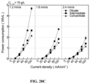
- FIGS. 28 A, 28 B and 28 C show the water cost optimization for RO brine treatment scenario.
- FIG. 28 A Schematic illustration of the process.
- FIG. 2 B Cost and recovery rate changes as a function of SRRatio for RF-ICP desalination with a fixed waste treatment cost, $5/m 3 .
- FIG. 2 C Water cost change as a function of waste treatment cost. (Numbers on the line indicate waste treatment costs, $/m 3 ).
- FIG. 29 is a schematic comparing the ICP with a bifurcated channel with normal flow (Bi-N; left side) and the CF-ICP system (referred to as a bifurcated channel with counter flow, Bi-C; right side) each having 30 cm of effective membrane length.
- the feed stream is bifurcated into a diluate stream and a concentrate on the cathodic and anodic sides of porous membrane, respectively.
- This architecture is characterized by large back diffusion and osmosis between cation exchange membranes (CEMs).
- CEMs cation exchange membranes
- the feed stream forms two streams, the concentrate stream which is directed to the outlet and the diluate stream which passes the length of the channel and then flows in a direction counter to that of the feed stream.
- FIG. 30 shows the concentration profiles of the Bi-C and Bi-N systems at feed flow velocities of 0.5 mm/s and 1.5 mm/s.
- the graph on the right side shows the salinity variation at the concentrate and diluate outlets with a feed salinity (C 0 ) of 70 g/l.
- FIG. 31 shows the current utilization (CU) of the Bi-C and Bi-N systems at feed flow velocities of 0.5 mm/s and 1.5 mm/s.
- the graph on the right side shows the change in CU of Bi-C and Bi-N versus current flux for 70 g/l feed salinity.
- FIG. 32 shows the concentration difference of the Bi-C and Bi-N systems at feed flow velocities of 0.5 mm/s and 1.5 mm/s.
- the graph on the right side shows the concentration (g/L) versus the current flux for 70 g/l feed salinity.
- FIG. 33 shows the power consumption for the Bi-C and Bi-N systems at feed flow velocities of 0.5 mm/s and 1.5 mm/s.
- the graph on the right side shows the power consumption according to salt removal ratio (SRRatio) for Bi-C, Bi-N, and RF-ICP for feed salinities of 70 and 100 g/l.
- SRRatio salt removal ratio
- ED electrodialysis
- Conventional electrodialysis generally operates at 80% of a limiting current regime for energy efficiency.
- an application of current should be increased and this current indispensable to enter an over limiting current regime.
- the over limiting current results in many side effects such as chaotic electroconvection in a dilute channel, and a back diffusion from concentrate to the dilute channel, or water splitting.
- the above phenomena have a negative impact on both desalination for purification of water and concentration for salt production.
- ED electrodialysis
- AEM anion exchange membrane
- CEM cation exchange membrane
- ICP ion concentration polarization
- Tri-ICP trifurcate ICP desalination architecture
- Tri-ICP trifurcate ICP
- FIGS. 2 A and 2 B A trifurcate ICP (Tri-ICP) desalination architecture
- a thin ion depletion region is extracted to achieve both good energy efficiency (only a thin depletion region is generated) and good salt removal ratio (incremental depleted/desalted stream is extracted).
- Using this architecture we have demonstrated cost-effective partial desalination of brine (from 70 g/L to 35 g/L) in a lab scale experimental system.
- Tri-ICP essentially relies on lower current electromembrane operation, and therefore requires recirculation of main fluid intake.
- the present application encompasses a newly designed channel for electrical water desalination/concentration technology.
- the systems and methods described herein include:
- ICP desalination, bifurcate, and trifurcate ICP desalination system have been described, for example, in U.S. Pat. App. Pub. No. 2014/0374274 A1, U.S. Pat. No. 9,845,252, U.S. Pat. App. Pub. No. 20170066665, U.S. Pat. No. 9,850,146, U.S. Pat. App. Pub. No. 2016/0115045 A1, Kim et al. (2016), Scientific Reports 6:31850; and Kwak et al. (2016), Sci Rep. 6: 25349, the contents of each of which are expressly incorporated by reference herein.
- ICP desalination results in both dilute and concentrate streams that are separately acquired between two identical ion exchange membranes (IEMs) ( FIG. 1 B ) whereas a conventional electrodialysis (ED) needs alternating differently charged IEMs, e.g., alternating an anion exchange membrane (AEM) and a cation exchange membrane (CEM) ( FIG. 1 A ).
- a trifurcate ICP desalination system and method is shown in FIGS. 2 A and 2 B which enables the collection of thin ion depleted and ion enriched layers which develop next to the IEM surface, by dividing outlets of the target stream within one channel unit ( FIGS. 2 A and 2 B ).
- ICP nonlinear ion concentration polarization
- IEMs ion exchange membranes
- ICP ion concentration polarization
- ICP desalination/concentration utilizes ICP between two identical IEMs. Between two juxtaposed similar ion exchange membranes (AEMs or CEMs), an ion depletion zone (d de ) and ion enrichment zone (d en ) are generated under an electric field. As cations are selectively transferred through the CEMs, for example, anions are relocated in order to achieve electro-neutrality, resulting in the concentration drop (increase) in the ion depletion (enrichment) zone.
- concentration drop or salt removal
- the over-limiting current is accompanied by two phenomena, chaotic electroconvection in the dilute stream and propagation of enriched salt from the concentrate stream, with an increase in energy consumption.
- the electroconvection in the dilute stream generates a chaotic flow motion which increases energy dissipation and causes an undesirable flow mixing.
- Highly enriched salt in the concentrate stream propagates to the dilute stream causing decline of salt removal efficiency.
- the dilute and concentrate streams were on the same channel component, and they can affect each other without any restrictions.
- the present invention can improve energy efficiency for desalination and/or salt production by minimizing chaotic electroconvection at the dilute stream and/or blocking enriched salt propagation from the concentrate stream.
- the present invention is directed to an ICP desalination/concentration system and method comprising a return flow system.
- the methods described herein produce at least two streams: a stream which has reduced ionic species and a stream which concentrated ionic species.
- the stream which has reduced ionic species can be referred to as the “dilute stream,” the “purified water stream,” the “diluate stream,” or the “diluate,” interchangeably herein unless otherwise indicated.
- the stream which has concentrated ionic species can be referred to as the “concentrate stream,” the “concentrated ion aqueous stream,” or the “concentrate” interchangeably herein unless otherwise indicated.
- FIGS. 3 to 5 describe specific embodiments of the return flow system for ICP. Specifically, FIGS. 3 , 4 and 5 are schematics showing a return flow system which results in a suppressive flow barrier, a return flow system which results in a preventive flow barrier, and a return flow system for united barriers, respectively.
- FIG. 3 represents a desalination application (CF-ICP) using a return flow system that results in a suppressive flow barrier.
- the inlet of the feed stream and the outlet of the dilute stream are installed in the same direction or on the same end of the channel (here, right side), but are separated by a porous membrane except the end of the channel for a return flow.
- the inlet of the feed stream is installed at the anodic side and the outlet of dilute stream is installed on the opposite side of the channel.
- the other stream, the discharge stream (the concentrate stream) is discharged through the outlet on the left side (the end of the channel opposite to the inlet end).
- the feed stream adjacent to the porous membrane partially flows through the membrane to suppress an electroconvection in the dilute stream. Then the feed stream at the end of porous membrane splits and returns to the right side of the channel to wash out the desalted mass near IEM.
- CF-ICP counter-flow ICP
- ED and ICP a high salt removal ratio require a large concentration polarization at the membrane interface.
- the large concentration polarization results in a larger trans-membrane concentration difference, leading to stronger diffusion and osmosis. This results in an increase in the total current application to compensate for the reverse transfer of salt.
- CF-ICP has two features to address the key challenge of enabling energy-efficient, high current desalination. First, the diluate stream effectively passes the channel twice, increasing in feed water dwell time, but the concentrate stream flows out without any dwell time increase. Second, one can reduce the concentrate difference along CEM ( FIGS. 8 A and 8 B , right side). The minimized trans-membrane concentration difference results in reduced diffusion and osmosis.
- the ion exchange membranes are CEMs
- the first outlet is located on the cathodic side of the first porous membrane
- the inlet is located on the anodic side of the first porous membrane
- the purified water stream is directed to the first outlet.
- the second outlet (to which the concentrate stream is directed) is located at the return flow end.
- the diluate stream passes through the channel twice whereas the concentrate stream flows out of the second outlet (at the return flow end) and effectively only passes through the channel once.
- the return flow end is closed on the cathodic side (but open at the anodic side). In this way, the concentrate stream is directed to the first outlet and the purified water stream is directed to the first outlet.
- FIG. 4 represents a concentration application using the CF-ICP system that results in a preventive flow barrier.
- the channel configuration for the concentration application is identical with the channel configuration for the desalination application of FIG. 3 , except with respect to the inlet and outlet positions.
- the inlet of feed stream is installed at the cathodic side of the channel while the outlet of concentrate stream is installed opposite direction.
- the feed stream flowing adjacent to the porous membrane flows through the membrane to prevent or suppress propagation of concentrated mass from the concentrate stream.
- FIG. 5 represents a desalination and concentration application using the return flow system resulting in united flow barriers (RF-ICP).
- the inlet of feed stream is located between the outlets for the dilute and concentrate streams and the left side of the channel is entirely blocked.
- the outlet of concentrate stream is placed on the anodic side of the channel and that of dilute stream is placed in the opposite direction.
- Each outlet is separated from the inlet by a porous membrane except the end of channel for the return flow.
- this configuration includes two porous membranes.
- the feed stream adjacent to the porous membranes flows through the membranes in two directions, a suppressive flow barrier for the dilute stream and a preventive flow barrier for the concentrate stream.
- the feed stream splits into two directions at the end of the porous membranes, to wash out the enriched mass and desalted mass on the IEM surface, respectively.
- the configuration shown in FIG. 5 is also referred herein as return flow ICP (RF-ICP). It is known that increased flow rate in the ED (at a given operating current) results in reduction in ion depletion region, therefore increased energy efficiency. Yet, this means that same amount of salt removed (same current) for larger volume of water processed, resulting in reduced salt removal ratio for product water. As discussed above, incorporating a return flow system re-routes the feedwater inside the ED or ICP channels.
- the ‘return-flow’ architecture (RF-ICP) is shown in FIGS. 7 A and 7 B . This system has three unique features to address the key challenge of enabling energy-efficient, high current desalination.
- the fluid effectively passes the channel twice (by return flow), effectively increasing the length of the channel (feedwater dwell time).
- the current and deletion layer are re-distributed along the membrane ( FIGS. 7 A and 7 B (right side). The current is more uniformly distributed along the membrane and the depletion layer was developed with a flat thickness, resulting in an overall resistance reduction.
- the ion exchange membranes are CEMs
- the second outlet is located on the inlet end of the channel
- the inlet is located between the first outlet and the second outlet
- the inlet and the second outlet are separated by a second porous membrane that traverses the length of the channel between the ion exchange membranes and terminates at the return flow zone, and the return flow end is fully closed.
- the flow rate of the outlet can be controlled independently. For collection of highly enriched mass from the concentrate stream, the outlet flow rate of concentrate stream can decrease. In the same manner, the outlet flow rate of dilute stream can increase for collection of a large volume of desalted mass.
- the pore size of porous membrane can be varied for control of suppressive and preventive flow through the membrane.
- the invention includes systems, devices, and methods for purifying and/or concentrating a first water stream containing ionic impurities comprising the steps of:
- the ion exchange membranes can be cation exchange membranes (CEMs) or anion exchange membranes (AEMs).
- CEMs cation exchange membranes
- AEMs anion exchange membranes
- the electric field can be created by an electrode and a ground each located external and parallel to the channel.
- the two ion exchange membranes can be the same or different. Strong anion or cation exchange membranes, as those products are generally sold in the art, are preferred.
- FUMASEP® FTAM-E and FTCM-E (FuMA-Tech CmbH, Germany) are suitable membranes.
- a suitable membrane is also a NAFION® membrane, for example, a NAFION® perfluorinated membrane available, for example, from Sigma Aldrich, USA. However, others can also be used.
- the term “ion exchange membrane” is intended to include not only porous, microporous, and/or nanoporous films and membranes, but also resins or materials through which ions can pass.
- an ion exchange resin can be entrapped by one or more meshes (or porous membranes) in lieu of or in addition to one or more of the ion exchange membranes.
- the ion exchange membranes comprise micrometer sized pores (or micro pores).
- the ion exchange membranes comprise nanometer sized pores (or nano pores).
- the ion exchange membranes comprise micro pores and nano pores.
- ion exchange membrane comprising micro pores and nano pores has been described, for example, in Kwon et al., (2015), A Water Permeable Ion Exchange Membrane for Desalination, 19 th International Conference on Miniaturized Systems for Chemistry and Life Sciences October 25-29, Gyeongju, Korea available at http://www.rsc.org/images/LOC/2015/PDFs/Papers/1202_T.302e.pdf, the contents of which are expressly incorporated by reference herein.
- the ion exchange membranes can be placed into a support, such as glass, polydimethylsiloxane or other inert material. Thus, the support can also contribute to the formation of the channels.
- FIGS. 3 to 5 show channels formed by cation exchange membranes (CEMs).
- CEMs cation exchange membranes
- Anion exchange membranes (AEMs) can also be used in the desalination/concentration methods described herein but the outlets for the purified water stream and concentrated ion aqueous streams are reversed.
- the ion exchange membranes are CEMs
- the first outlet is located on the cathodic side of the first porous membrane
- the inlet is located on the anodic side of the first porous membrane
- the purified water stream is the stream directed to the first outlet; optionally, the second outlet is located at the return flow end.
- the terms “anodic side” and “cathodic side” are used in reference to the side of the channel proximal to the anode and the cathode, respectively.
- the second outlet can be located at the return flow end, for example, the second outlet is located on the part of the return flow end that is not closed and that is on the same side (anodic or cathodic) as the inlet (see, for example, FIGS. 3 and 8 A ).
- the ion exchange membranes are CEMs and the first outlet is located on the anodic side of the porous membrane, the inlet is located on the cathodic side of the porous membrane, and the concentrated water stream is directed to the first outlet.
- the second outlet can be located at the return flow end, for example, the second outlet is located on the part of the return flow end that is not closed and that is on the same side (anodic or cathodic) as the inlet.
- the part of feed stream that forms the return flow stream can, for example, be the feed stream that enters the closed portion of the return flow zone (wherein the closed portion of the return flow zone is that portion adjacent to the closed part of the return flow end).
- the return flow stream then flows in the direction of the first outlet (e.g., cross-current to the feed steam entering the inlet) and is directed to the first outlet.
- the return flow stream is the dilute stream and the closed portion of the return flow end is on the side of the channel that the diluate is formed.
- the second outlet is located on the inlet end, the return flow end is fully closed, the inlet is located between the first outlet and the second outlet, and the inlet and the second outlet are separated by a second porous membrane that traverses the length of the channel between the ion exchange membranes except at the return flow zone.
- the first outlet is located on the cathodic side of the first porous membrane (the membrane separating the inlet and the first outlet), and the second outlet is located on the anodic side of the second porous membrane; and the purified water stream is the stream (e.g., the first return flow stream) directed to the first outlet, and the concentrated ion aqueous stream is the stream (e.g., the second return flow stream) directed to the second outlet.
- the feed stream enters the return flow zone (for example, the closed portion of the return flow zone) and forms a second return flow stream that flows to the other side of the second porous membrane as the feed stream (the opposing side) and flows in the direction of the second outlet.
- the feed stream adjacent to the second porous membrane flows through the second porous membrane joining the second return flow stream.
- the purified water stream and the concentrated ion aqueous streams are collected from the first and the second outlets, respectively.
- FIGS. 3 to 5 show channels formed by cation exchange membranes (CEMs).
- Anion exchange membranes (AEMs) can also be used in the desalination/concentration methods described herein but the outlets for the purified water stream and concentrated ion aqueous streams would be reversed.
- CEMs the ion concentration is depleted at the cathode side (ion-depleted region) and concentrated at the anode side (ion-enrichment region).
- AEMs the ion concentration is depleted at the anodic side (ion-depleted region) and concentrated at the cathodic side (ion-enrichment region).
- CEMs are used as the ion exchange membranes forming the channel that provides a suppressive flow barrier (e.g., FIG. 3 )
- the inlet is located on the anodic side and the outlet for the purified water stream is located on the cathodic side of the channel.
- AEMs are used to provide a suppressive flow barrier (e.g., in a system analogous of FIG. 3 ) then the inlet is located on the cathodic side of the channel and the outlet for the purified water stream is located on the anodic side of the channel.
- AEMs are used to provide a preventive flow barrier (e.g., analogous to the system of FIG.
- the inlet is located on the anodic side of the channel and the outlet for the concentrated solution is located on the cathodic side of the channel.
- the outlet for the purified stream is located on anodic side and the outlet for the concentrate ion aqueous stream is located on the cathodic side of the channel.
- the channels described herein include at least two outlets, for example, one outlet is for the purified water stream and the other outlet is for the concentrate ion aqueous stream.
- one outlet is for the purified water stream and the other outlet is for the concentrate ion aqueous stream.
- the purified water stream is the stream directed to the first outlet (the return flow stream) or the stream directed to the second outlet depends on where the outlet is located on the end of the channel relative to the inlet (e.g., on the anodic or cathodic side), and whether the ion exchange membranes are CEMs or AEMs.
- the concentrate ion aqueous stream is directed to the other outlet of the at least two outlets (in other words, to the outlet to which the purified water stream is not directed).
- the “first outlet” is the outlet located next to the inlet and is thus on the same end of the channel as the inlet.
- the second outlet is located at the return flow end, which is the end of the channel opposite to the end that the inlet is located.
- the second outlet is located on the same end of the channel as the inlet and the first outlet.
- the inlet can, for example, be located between the first and second outlets.
- At least one porous membrane is used to separate the inlet and the first outlet and the porous membrane traverses the length of the channel except at the return flow end, thus the porous membrane traverses the length of the channel and terminates at the return flow zone.
- a porous membrane is used to separate the inlet and the second outlet and the porous membrane traverses the length of the channel except at the return flow end.
- the porous membrane can, for example, be a non-ionic porous membrane.
- the porous membrane can be microporous and/or nanoporous.
- the porous membranes comprise, for example, pores about 1 nm to about 2 um or about 100 nm to about 2 um, or about 1 um to about 2 um in size. In certain additional aspects, the pores are about 1 um diameter pores.
- the porous membrane(s) can be located parallel or substantially parallel to the ion exchange membranes.
- a non-ionic porous membrane is a porous membrane that is not an ion exchange membrane, or that is not charged and thus does not only allow cations or anions to pass through.
- the non-ionic porous membrane can allow fluid and ions (cations and anions) to pass through.
- the feed stream directed into the channel via the inlet flows from the inlet in the direction of the return flow end. At least part of the feed stream adjacent to the porous membrane flows through the porous membrane to the opposing side of the membrane (flows to the other side of the membrane as that of the feed stream entering through the inlet).
- the return flow zone is the section of the channel at the return flow end that is not traversed by the porous membrane and/or where the porous membrane is not present. At least part of the feed stream that flows to the return flow zone forms a return flow stream that flows to the to the other side (or opposing) of the first porous membrane (flowing around the end of the porous membrane) and flows in the direction of the first outlet (cross current to the flow of the flow stream entering the inlet).
- the purified water stream is the stream directed to the first or the second outlet, and the concentrated ion aqueous stream is the stream directed to the other of the first and the second outlet.
- the return flow stream is the purified water stream or the concentrated ion aqueous stream (depending on which stream is directed to the first outlet).
- the channel formed by the two juxtaposed ion exchange membranes does not contain a membrane carrying a charge counter to the two juxtaposed ion exchange membranes.
- the consequence of the configuration is that only positive (or negative) ions, but not both participate in conduction.
- the ions in the electrolyte solution or aqueous stream to be purified that participate in the conduction in the apparatus, or cell, carry a common charge, while the counterions or ions carrying the opposite charge, while present, do not participate in conduction.
- the invention preferably excludes the use of an apparatus that traditionally functions via electrodialysis.
- the electric field can be generated by an electrode and a ground each located external and parallel to the channel.
- the electric field can be generated, for example, by an anode and a cathode.
- An electrode can form another channel (e.g., a second channel) with the first ion exchange membrane, for example, an anode can form a second channel with the first ion exchange membrane.
- the ground, or for example the cathode can form yet another channel (e.g., a third channel) with the second ion exchange membrane.
- the second and third channels can be filled with an electrolyte solution.
- the electrolyte solution is the first water stream.
- the first water stream comprises a salt.
- the first water stream comprises biomolecules.
- the first water stream can, for example, be water with a range of salinities, for example, brackish water, seawater, produced water, and brine.
- brackish water can refer to water having a salinity less than about 10,000 ppm and/or having an NaCl concentration greater than about 0.5M NaCl.
- produced water can have a salinity greater than about 30,000 ppm.
- brine can refer to water with higher salinity than 35,000 mg/L TDS and/or water having an NaCl concentration greater than about 1M NaCl.
- the first water stream can be wastewater, for example, brackish groundwater, household water rich in bacteria or other biological contaminants, or simply murky water from various suspended solids and/or industrial heavy metal contaminants.
- Biomolecules include cells (such as bacteria or animal), cellular fragments, particles (including viral particles), proteins, and nucleic acid molecules, for example.
- the electric field preferably creates a boundary layer comprising at least one electroconvective vortex proximal to at least one of the two juxtaposed ion exchange membranes.
- the electric field is created by an electrode and a ground, each located external and parallel to the channel.
- the electrode forms a second channel with the first of said two juxtaposed ion exchange membranes and the ground forms a third channel with the second of the two juxtaposed ion exchange membranes.
- These channels are generally filled with an electrolyte solution, which can conveniently be the water stream to be purified or concentrated.
- the invention additional encompasses a device comprising the channel and the return flow system as described herein.
- Electrodialysis is an electrically-driven membrane desalination technology that removes anion through anion exchange membrane (AEM) and cation through cation exchange membrane (CEM).
- AEM anion exchange membrane
- CEM cation through cation exchange membrane
- the systems and methods include a double flow barrier using a return-flow system for ED desalination/concentration.
- FIG. 6 is an example of such a system.
- FIG. 6 is a schematic showing a return flow system facilitating double flow barrier for a conventional electrodialysis.
- the installation and operating mechanism are similar to the united flow barrier system for ICP desalination/concentration shown in FIG. 5 , but the purpose of barrier is different.
- the dilute and the concentrate channel are separated by IEM whereas they are placed in the same channel in the ICP desalination/concentration.
- the united flow barriers which have two different barrier functions, a suppressor and a preventer, are operated as double flow barriers which have two barriers in the channel, but same feature, in the conventional electrodialysis.
- the return flow system and barriers result in the collection of a thin depleted and enriched mass layer next to IEM surface and can result in a reduction of energy consumption.
- the invention is directed to a system or method of purifying and/or concentrating a first water stream containing ionic impurities by electrodialysis comprising the steps of:
- the porous membranes can, for example, be non-ionic porous membranes.
- the non-ionic porous membranes can be the same or different.
- the first and third IEMs are cation exchange membranes
- the second IEM is an anion exchange membrane
- the fluid directed to the outlets of the first channel is the concentrated ion aqueous stream
- the fluid directed to the outlets of the second channel is the purified water stream.
- first and third IEMs are anion exchange membranes and the second IEM is a cation exchange membrane, and wherein the fluid directed to the outlets of the first channel is the purified water stream, and the fluid directed to the outlets of the second channel is the concentrated ion aqueous stream.
- the device comprises an electrolytic cell with a cation exchange membrane (CEM) that separates the solutions in contact with anode and cathode respectively.
- CEM cation exchange membrane
- the anode is composed of a metal, typically aluminum or iron, and is used to provide metal ions for electrocoagulation.
- This hybrid system can remove both salt and particles, it has the flexibility to treat various types of wastewater, whether it be brackish groundwater, household water rich in bacteria or other biological contaminants, or simply murky water from various suspended solids and/or industrial heavy metal contaminants.
- the hybrid device can also be used for produced water treatment such as found in the shale gas industry, where suspended solids removal is crucial for re-use in hydraulic fracturing.
- the product from the CEM outlet is free of salt and suspended solids.
- This water can be used as a fresh feed solution, which is mixed with the produced water, for hydraulic fracturing.
- 90% of produced water is recycled in shale gas wells, mixed with fresh feed. Therefore, a relatively small portion of desalinated water may be sufficient to be used as fresh feed in produced water recycling.
- the ICP-EC system has a wide range of applications in wastewater treatment system. It can be used as a single-device water treatment system. It does not require additional pre-treatment.
- Salt removal ratio is a parameter to indicate the desalting ability of devices. By measuring the concentration (or conductivity) of sample flows C 0 and that of the desalted flow C desalted , we can figure out how many salt ions are removed from the discrepancy between the two conductivities. Salt removal ratio is non-dimensional form of the amount of desalted ions by the initial ion concentration (or conductivity):
- the concentrations can be converted from the measured conductivity ⁇ in experiments with given molar conductivities of electrolytes.
- 10 mM KCl 10 mM KCl
- NaCl NaCl
- LiCl solutions 10 mM KCl
- LiCl solutions 10 mM KCl, NaCl, and LiCl solutions.
- energy consumption for desalination is electrical power consumption (multiplication of current I and voltage V) divided by the flow rate of desalted water Q desalted per one cell:
- EIR Energy per ion removal
- Area ⁇ efficiency C 0 - C desalted A [ mM / m 2 ] , where A is the working area of IEMs here.
- A the working area of IEMs here.
- the most significant cost of an electrochemical desalination system is the membrane cost, therefore higher area efficiency would be economically favorable.
- the platforms described here, ICP with two CEMs (2CEM), or AEMs (2AEM), and ED, are fabricated to study the differences and any potential advantages of each technique.
- the height h, width w, and length L of the working channel is 0.2, 2, and 10 mm, respectively.
- the area of working IEMs is therefore 2 ⁇ 10 ⁇ 6 m 2 .
- Three different electrolytes (10 mM KCl, NaCl, and LiCl) with 10 mM concentration are used to observe the effect of asymmetric molar conductivity (or diffusivity) of cation and anion.
- the flow rate between IEMs is 20 ⁇ L/min, so the desalted flow rates Q desalted are 10 ⁇ L/min for ICP platform and 20 ⁇ L/min for ED.
- the electrodes are rinsed with the same electrolytes (KCl or NaCl or LiCl) with 30 ⁇ L/min; dibasic buffer solution is not used here to supply the same cations or anions within the sample water.
- Cl ⁇ governs ICP platform with two AEMs with KCl, NaCl, and LiCl solutions.
- the movement of cation governs ICP platform with two CEMs and ED, because chorine ion has a higher molar conductivity than cations here. If we place ions in the order of higher molar conductivity (proportional to electrophoretic mobility or diffusivity), it is Cl ⁇ >K + >Na + >Li + . Accordingly, in ICP with 2CEM and ED, the current values with K + are higher than that with Na + and Li + .
- a limiting current density (LCD) is linearly proportional to the diffusivity (or molar conductivity) of conducting ions.
- the limiting current can be selected at the location where the current-voltage curve is bent.
- the voltage-current responses show the similar tendencies.
- the energy consumptions of ED and ICP with 2CEM are matched when the same electrolyte is used.
- ICP with 2AEM chlorine ions can move faster with higher molar conductivity, resulting in lower cell resistance, lower voltage responses at a given current, and lower energy consumptions than the other two systems.
- salt removal ratio of ICP with 2AEM are worse than both ICP with 2CEM and ED; ICP with 2CEM shows larger salt removal ratio than ED, meaning that with the same amount of driving current, ICP (2CEM) can move more ions from the desalted flow output.
- the salt removal ratio is constant (ED) or higher (ICP with 2CEM) or lower (ICP with 2AEM).
- This ambitendency of the salt removal ratio at a constant applied current is also shown in the current efficiency.
- the current efficiency of ICP with 2CEM (2AEM) always better (worse) than ED, and the trend is magnified the cation molar conductivity is lower. This phenomenon will be discussed in detail in the next section.
- Energy per ion removal represents the combined efficiency of both energy consumption and salt removal.
- Energy per ion removal of ICP with 2AEM have the lowest values, as like energy consumption. However, energy per ion removal of ICP with 2CEM becomes better than that of ED. It is because of higher salt removal ratio of ICP with 2CEM and that of ED, even the energy consumptions are the same. In all three systems, removing slow ions (Li + ) require more energy than the other faster ions (K + and Na + ).
- Energy per ion removal in overlimiting regime is O (10 3 k B T), but it becomes O (10 k B T) in Ohmic regime, which is comparable with state-of-the-art CDI systems.
- Example 1 Return Flow Ion Concentration Polarization Desalination: A New Way to Enhance Electromembrane Desalination
- FIG. 11 D shows a schematic illustration of RF-ICP desalination with three channels separated by two porous membranes.
- RF-ICP has the same channel architecture as Tri-ICP, which has the three channels composed of a concentrate channel on the anodic side, a diluate channel on the cathodic side and an intermediate channel between them. However, the intermediate channel outlet of Tri-ICP is replaced by the feed inlet of RF-ICP, and the feed inlet of Tri-ICP is entirely closed.
- RT-flow return-flow
- the feed solution enters through the inlet of the intermediate channel. Then, it flows to the end of channel and returns to the outlet of the two channels as separating into two channels, a diluate and a concentrate channel.
- RT-flow sweeps a mass thereby collecting thin ion depleted and concentrated layer, developed adjacent to CEM.
- the pressure difference generates the other flow that flows from the intermediate channel to both side channels via the porous membranes (PM-flow).
- the modified lab-scale ICP desalination is prepared, with configuration, fabrication, and operation as described and demonstrated in a previous work.
- the spacer comprised three channels, diluate, intermediate and concentrate channel.
- the intermediate channel is fabricated with clear cast acrylic sheet with 1.6 mm-thick and the nanoporous membrane (poly-carbonate membrane filter with 200 nm pore, Sterlitech Co., Kent, Wash., USA) were attached both sides of intermediate channel.
- the diluate and concentrate channels prepared with silicon rubbers with 0.8 mm-thick, were attached both sides.
- Three spacers were stacked and divided by four pieces of CMX, heterogeneous Neosepta CMX (Astom Co., Japan) with 15 ⁇ 5 cm 2 of the effective membrane area.
- Flow rates for diluate and concentrate stream are controlled by needle valve (7792K55, McMaster, Robbinsville, N.J., USA) and monitored by flowmeter (4350K45, McMaster).
- the real-time conductivity change is monitored by flow-through conductivity probe (16-900 Flow-thru Conductivity Electrode, Microelectrode, Inc., Bedford, N.H., USA) and then the diluate and concentrate solutions are collected after 5 minutes when the flow-through conductivity probe shows a saturated conductivity.
- the collected solutions are measured by electrode conductivity cell (013610MD, Thermo Fisher Scientific Inc., Cambridge, Mass., USA).
- the DC power supply (9205, B&K Precision Cor., Yorba Linda, Calif., USA) was used for an application of constant current and the Digital multimeter (5491B, B&K Precision Cor.) was used for a voltage drop between spacers.
- two flow rate sensors and two needle valves are installed to measure and control the flow rate of concentrate channel outlet (Q C,out ) and diluate channel outlet (Q D,out ), respectively.
- the outflow from intermediate channel directly returns to both the concentrate and diluate channel, but intermediate channel extended with tube and split two directions to measure the flow rate of return flow (RT-flow) to the concentrate channel (Q C,R ) and diluate channel (Q D,R ).
- the two RT-flows are balanced by the needle valves to have a same flow rate before an application of electric field.
- the flow though the porous membranes (Por-flow) towards the concentrate (Q C,P ) and diluate channel (Q D,P ) are calculated as the difference between the flow rate of outflow and Re-flow.
- the conductivities of the outlets of each channel are measured.
- the flow velocities of concentrate outlet (u C,out ), diluate outlet (u D,out ), Re-flow to concentrate (u C,R ) and Re-flow to diluate (u D,R ) are calculated by dividing the corresponding flow rate by the width and height of the channel.
- the flow velocities of Por-flow to concentrate (u P,C ) and diluate (u P,D ) is calculated by dividing the corresponding flow rate by the width and length of the porous membrane.
- the channel and porous membrane have the same width (35 mm), but length of porous membrane (150 mm) is 187.5 times longer than the height of channel (0.8 mm).
- voltage drop within the channel (V ch ) is measured and the average resistivity ( ⁇ ) of each channel is calculated based on the measured conductivity ( ⁇ ) with following equation:
- Tri-ICP ( FIG. 13 A ) and RF-ICP ( FIG. 13 B ) are schematically illustrated in FIGS. 13 A and 13 B . Both systems have same spacer dimension and membrane area. The different feed flow rate is applied to have a same flow velocity at the diluate and concentrate outlet. The three channels have the same width and length but have different channel heights at a ratio of 1:2:1 (diluate: intermediate: concentrate). RF-ICP has a half of feed flow rate of Tri-ICP in order to have the same flow rate of diluate and concentrate flow rate for both systems. This flow path improves the recovery rate from 25% to 50% without any additional flow control. The outlet flow rates are monitored by flow meter to maintain a constant flow rate.
- the current utilization (CU), power consumption (P) and energy per unit ion (EPI R) is calculated as follows:
- Numerical simulation result is obtained after solving the governing equations including Nersnt-Planck equations for ion transport (Eq. 1-2), Poisson's equation for the dependence of electric potential fields on the ion concentrations (Eq. 3-4), and Navier-Stokes and continuity equations (Eq. 5-6) for fluid motions inside the channel. Dimensionless form of these equations is as following:
- C 0 the concentration scale
- l 0 the characteristic length scale
- D 0 the average diffusivity
- k B the Boltzmann constant
- T is the absolute temperature
- e the elementary charge
- Z
- ⁇ is the dynamics viscosity of solution
- ⁇ tilde over (D) ⁇ ⁇ D ⁇ /D 0
- ⁇ tilde over ( ⁇ ) ⁇ D ⁇ D /l 0
- Pe U 0 l 0 /D 0
- Sc ⁇ / ⁇ m D 0
- a Hagen-Poiseuille pressure-driven flow of electrolyte solution is defined at the inlet boundary. Since the inlet of Tri-ICP is identical to the channel height, while the RF-ICP's inlet is two time smaller, the inlet flowrate of Tri-ICP need to be two times higher than that of RF-ICP to equalize their dilute flowrate, which is 25% of the inlet flowrate. All parameter used here described in Table 1.
- the experiment set-up is schematically illustrated in FIG. 15 .
- Three RF-ICP desalination spacers are stacked with the cation exchange membranes, alternatively.
- the effective voltage is measured in the same manner as the previous measurement.
- Two platinum electrodes are placed next to the membrane to measure the voltage drop in the channel.
- the experiment condition is in Table 2.
- a m , K Q and Q d are membrane area (m 2 ), area normalized equipment cost ($750/m 2 membrane) and diluate flow rate (m 3 /h), respectively.
- T and R are lifespan (year) and annual interest rate (10%).
- V, I and K E are voltage (V), current (A) and electricity cost ($/kWh).
- Q RO,p and Q RO,b are the produced water and brine from RO, respectively.
- Q ICP,b is the brine from RF-ICP.
- U P slightly increases under higher U F and C F .
- U P is determined by a pressure difference between the intermediate stream and both side streams (diluate and concentrate streams).
- the pressure difference results from the energy loss due to friction by shear stress, which is changed by viscosity, density and velocity. Higher salinity brings higher viscosity and density which lead increase in pressure drop along the traveling the channel.
- the flow distribution is changed with an application of current flux ( FIG. 16 ).
- U P for diluate stream (U P,D ) increases with increase in current flux whereas U P for concentrate stream (U P,C ) maintains initial velocity.
- U P for concentrate stream U P,C
- the increasing tendency of U P decreases as U F and C F increases. This change can be simply explained by electro-osmotic flow through the negatively charged polycarbonate porous membrane. Firstly, large potential drop promoting the electro-osmotic flow is formed across the porous membrane in contact with the diluate stream., but higher velocity and feed salinity reduce the potential drop as decrease
- FIGS. 17 A-C shows the salinity variation at outlets of two channels, diluate and concentrate channel, and end of intermediate channel.
- Higher U F shows a symmetric salinity profile change, but lower U F shows an asymmetric salinity profile change with a delayed increase in salinity for the concentrate stream, indicating a salt precipitation on CEM.
- the salinity of the intermediate stream increases with the salinity of concentrate stream, indicating that the highly concentrated salt in the concentrate stream leaks into the intermediate stream.
- the resistivity and power consumption of each stream is calculated in FIGS. 19 A- 19 C and FIGS. 20 A- 20 C .
- the resistivity of the diluate stream exponentially increases with increase in current flux due to relation between salinity and resistivity ( FIG. 21 ), while the resistivity of the intermediate and concentrate streams decrease due to the increase in salinity.
- the power consumption of diluate stream is not significantly higher than other streams under a lower salt removed condition, but most of the power consumed by diluate stream under a higher salt removed condition is due to its rapid increase in resistivity. In some cases, the power consumptions for intermediate and concentrate stream decrease rather than increase due to the resistance decrease.
- FIGS. 22 A- 22 C shows the effect of systems on CU, calculated from the experimental results, with respect to C F and current flux.
- CU of both systems gradually decreases as the current flux increases for all C F .
- the higher current flux leads to a thicker depletion and concentration layer on the opposite side of CEM.
- the development of trans-membrane concentration difference promotes stronger back-diffusion and osmosis, resulting in the reduction of CU.
- Both systems show higher CU value under higher U F .
- RF-ICP shows higher CU than that of Tri-ICP. Even both systems have a same outlet flow velocity, Tri-ICP has higher a horizontal velocity component along the membrane than that of RF-ICP. If we consider only the horizontal velocity component, CU of Tri-ICP should be higher than that of RF-ICP, because a higher velocity improves CU.
- the configuration of RF-ICP facilitates the vertical mass transport by PM-flow and increases the traveling length where water experiences an ion separation.
- SRRate can provide the removed mass per unit time, but SRRatio can only represent the ratio of removed mass fraction ( FIG. 24 ). Less EPIR is required at higher feed salinity and flow velocity to achieve same SRRate. A large amount of ion with a high salinity solution is easily transported to and through the membrane, and a higher flow velocity increases mass transport near the membrane, reducing depletion layer.
- Tri-ICP creates a thicker depletion layer along the membrane, rapidly deteriorating CU and EPIR, whereas RF-ICP develops a thinner depletion layer with good CU and EPIR.
- This trend is more apparent when a lower feed velocity generates a thicker depletion layer.
- higher velocity leads to an increase in mass transfer leading to a uniform current distribution along CEM.
- RF-ICP leads to a uniform current distribution, improving a desalination performance, with a same feed velocity, but doubles a recovery rate.
- RF-ICP has better desalination performance even Tri-ICP has a higher flow velocity near diluate side of CEM than RF-ICP.
- Tri-ICP with porous membranes has a better energy efficiency than Tri-ICP without porous membranes.
- RF-ICP facilitates an improved desalination performance, including energy efficiency and recovery rate, with a simple flow configuration change using same channel architecture.
- the performance of RF-ICP is evaluated to achieve a fixed SRRatio (10, 30, 50, 70, 95%) from various feed salinities and flow velocities ( FIGS. 26 A- 26 B ).
- the details of experiment setting and experiment conditions are provided in FIG. 15 and Table 2.
- the maximum current flux was limited to 250 mA/cm 2 .
- the harsh condition, requiring a current flux over 250 mA/cm 2 leads to malfunctions in CEM, creating a confused concentration profile and a bubble formation in the spacer. Higher power is required to promote pure and fast desalination, which indicate higher SRRatio and flow velocity, respectively.
- the other application is a partial desalination of highly saline brine (70 g/L).
- the power consumption has been reported to range from 19 to 21 Wh/L, desalting similar salinity changes (90 g/L to 40 g/L) for multi-stage brine desalination.
- the lab-scale Tri-ICP has required 5.6 to 213 Wh/L to achieve 50% of SRRatio with 70 g/L [8].
- RF-ICP requires a power consumption of 23.2 to 49 Wh/L to achieve 50% of SRRatio. This power consumption is quite competitive value, because RF-ICP is continuous processes and facilitates an improved recovery rate from 25% to 50% without re-circulation and reduction of membrane length from 30 cm to 15 cm.
- Power consumption is an important for a desalination application, but it is much more important to calculate a total water cost, composed of capital and operating cost, to evaluate a validity of technology in a practical desalination application.
- the simplified water cost model is applied for a water cost optimization (See Section 1.6 for details).
- the model includes capital and operating costs to determine the water cost.
- the capital cost is mainly determined by equipment lifespan and its cost.
- An increase in the equipment lifespan, determined by the lifespan of membrane, can reduced capital cost.
- Even the lifespan of commercial membrane is guaranteed for 10 years according to the specifications provided by the membrane manufacturer.
- ion exchange membranes have a lifetime of 4 to 10 years while maintaining selective permeability, depending on the type of feed solution due to fouling problems [20-22].
- the equipment cost is dominated by a membrane cost and its size in the electromembrane desalination. Especially, the membrane size is inversely correlated with the energy efficiency.
- the lifespan and electricity cost are set as 5 and 10 year, $0.05 and $0.1/kWh, respectively.
- the optimized water cost for RF-ICP is $4.01/m 3 ($1.69 and $2.32/m 3 for capital and operating cost, respectively) with a lifespan of 10 years and an electricity cost of $0.1/kWh. It can be reduced to $2.57/m 3 (0.85 and 1.72 $/m 3 for capital and operating cost, respectively) with a reduced electricity cost of $0.05/kWh, albeit the same lifespan.
- the changes in capital and operating cost provide changes in water cost, but also system characteristics and their applications.
- the operating costs, determined by electricity costs, used for both RF-ICP and Tri-ICP increase dramatically with increasing SRRatio, indicating that all ICP desalination is basically power intensive process, regardless of membrane size.
- Tri-ICP can further reduce capital costs by increasing lifespan due to differences in membrane size, although extending the lifespan of RF-ICP desalination plants has a relatively small capital cost savings.
- Tri-ICP could reduce the capital cost from $7.72 to $4.51/m 3 , maintaining operating cost as $4.00/m 3 with the increase in lifespan from 5 to 10 year, whereby the water cost is reduced from $11.72 to $8.51/m 3 .
- RF-ICP could hardly reduce the water cost from $9.19 to $8.79/m 3 . This result provides that ICP desalination is suitable technology for the region where has low electricity costs, while the smaller system ICP desalination is more sensitive to electricity costs.
- the brine wastes can be disposed to a well or recycled by a post-treatment such as mechanical vapor recompression (MVR), which leads to additional cost ($4.7 to 18.9/m 3 and $22 to 39/m 3 are waste treatment cost by evaporation pond and MVR, respectively).
- MVR mechanical vapor recompression
- This additional cost should be considered to be part of the desalination costs and it accounts for the majority of the water cost calculations because RO, ranging $0.71 to 0.91/m3, has little change in cost.
- FIG. 28 A illustrates RO process incorporated RF-ICP and waste treatment process.
- RO cost model developed Lienhard's group[31], fixed waste treatment costs and RF-ICP cost model with lifespan of 10 years and electricity cost of $0.05/kWh.
- the feed salinity (C F ) is set as a seawater salinity, 35 g/L, and the brine salinity (C RO,b ) from SWRO is fixed as 70 g/L.
- the brine (Q RO,b ) is partially desalinated by RF-ICP and the produced water (Q ICP,p ) and brine (Q ICP,b ) by RF-ICP are recirculated into the RO inflow (Q RO,in ) and discharged to waste treatment, respectively.
- the feed salinity for RO (C RO,in ) can change depend on the SRRatio of RF-ICP desalination, but it is limited to 30 to 45 g/L, which can be applied to typical RO.[32] In FIG. 28 B , the total water cost varies with change in RO, RF-ICP and waste treatment costs.
- the RF-ICP desalination can achieve a total water cost as $2.57/m 3 under conditions with $0.05/kWh and a lifespan of 10 years to reduce the feed salinity from 70 g/L to 35 g/L.
- Second scenario was a RO cost variation, which included wastewater treatment cost.
- the RF-ICP was applied to reduce the volume of waste and was a cost-effective when the wastewater treatment cost is higher than $3/m 3 .
- ICP desalination is new ion separation process in the field of electromembrane process. It indicates that ICP desalination technology can achieve improvement of energy efficiency and recovery rate by applying a well-developed technology in the ED field to the ICP desalination technology. While the similar idea can be applied to conventional ED (RF-ED), we validated the idea in ICP desalination process.
- ion-depleted boundary fluid layers constitute the desalted, product fluid stream, yet they also result in high resistivity and lowered energy efficiency.
- Manipulating fluid flow streams directly e.g. spacers
- return-flow architecture a novel electromembrane desalination architecture was studied that allows a feed stream to return to the feed direction (hereby named as return-flow architecture) to improve energy efficiency by limiting and controlling the size of depleted boundary layer, even at high current values.
- ICP desalination process with a wide range of feed salinity from 10 to 70 g/L.
- Brackish water (10 g/L) can be desalinated into potable water salinity (0.5 g/L) with a small size device (75 cm 2 of effective membrane area) at the energy efficiency of 33.7 Wh/L.
- RF-ICP desalination achieved overall water cost of $2.57/m 3 ($0.41/barrel).
- ICP desalination is created by employing a unipolar membrane system (e.g. only using CEMs), which will create two zones (brine and desalted) within the channel between the membranes.
- separation of brine and desalted flow is achieved by the fluidic split at the end of the system.
- a high-flow scale-up (shown in FIGS. 29 to 33 ) can be achieved by stacking CEMs in a similar manner to a conventional electrodialysis (ED).
- FIGS. 29 to 33 compare the bifurcate ICP (Bi-N) with the CF-ICP (referred to as “Bi-C” in FIGS. 29 to 33 ). Concentration profile, Current utilization, and Power Consumption were measured as described above in Example 1.
- FIG. 31 shows changes in current utilization, feed velocity, and current flux. CUs of both systems gradually decrease with the increase in current flux. Also, CU increases with the increase in feed velocity. Bi-C shows an improved CU as compared to Bi-N for all cases.
- the concentration difference between the outlet of concentrate stream and the stream across the CEM beside the concentrate stream was obtained to estimate the effect of trans-membrane back diffusion which reduces desalination performance ( FIG. 32 ).
- the concentration difference of Bi-N is higher than that of Bi-C.
- the higher concentration difference can result in higher trans-membrane back diffusion which reduces desalination performance.
- Bi-ICP requires the highest power consumption among the spacers, given the same conditions. Because Bi-ICP simultaneously collects a large amount of streams including a thick bulk layer and a thin depletion layer. Then, Tri-ICP ( FIG. 9 B ) facilitates the collection of thin depletion layer in the diluate stream but suffers from reduced recovery rate. Tri-ICP significantly improves energy efficiency as compared to Bi-ICP, generating and collecting thin depletion layer and minimizing depletion layer thickness.
- RF-ICP FIG. 9 C ), using the same channel structure as Tri-ICP, still facilitates the collection of thin depletion layers, but increases the effective channel length by simply changing the flow path.
- CF-ICP ( FIG. 9 D ), inspired by Bi-ICP, increases the effective channel length for diluate stream, but maintains the effective channel length for concentrate stream. By reversing the direction of growth of the two streams, diluate and concentrate streams, CF-ICP reduced a trans-membrane concentration difference, resulting in a reduction in back diffusion and osmosis. Therefore, it was shown ( FIGS.
Abstract
Description
-
- a. directing the water stream into an inlet of a channel, wherein the channel is defined, at least in part, by a first ion exchange membrane and a second ion exchange membrane, wherein the ion exchange membranes are juxtaposed and characterized by the same charge;
- wherein the channel is further characterized as having an inlet end and a return flow end, wherein the inlet end is the end of the channel at which the inlet is located, and the return flow end is the end of the channel opposite to or downstream, with respect to the inlet, from the inlet end;
- the channel further comprising at least two outlets, e.g., a first outlet and a second outlet, wherein the inlet and at least the first outlet are located on the inlet end of the channel and are separated by a first porous membrane that traverses the length of the channel between the ion exchange membranes and terminates at a return flow zone, wherein the return flow zone is a section of the channel at the return flow end, and wherein the return flow end is at least partially closed;
- b. applying an electric field across the channel causing formation of an ion depletion zone comprising a purified water stream and formation of an ion enrichment zone comprising a concentrated ion aqueous stream;
- wherein at least part of the feed stream enters the return flow zone and forms at least one return flow stream that flows to the opposing side of the first porous membrane (as compared to that of the feed stream), the first return flow stream flows in the direction of (or toward) the first outlet (e.g., cross-current to the flow of the water stream entering the inlet), and at least part of the feed stream adjacent to the first porous membrane flows through the first porous membrane joining the return flow stream;
- wherein a purified water stream is the stream directed to the first or the second outlet, and the concentrated ion aqueous stream is the stream directed to the other of the first and the second outlet; and
- c. collecting the purified water stream and/or the concentrated ion aqueous stream from the first and/or second outlet.
- a. directing the water stream into an inlet of a channel, wherein the channel is defined, at least in part, by a first ion exchange membrane and a second ion exchange membrane, wherein the ion exchange membranes are juxtaposed and characterized by the same charge;
-
- a. directing the first water stream into an inlet of a first channel and into an inlet of a second channel of an electrodialysis unit forming a first feed stream and a second feed stream, respectively;
- wherein the electrodialysis unit comprises at least three stacked ion exchange membranes (IEMs), wherein the first and the third IEMs have the same charge polarity, and the second IEM has the opposite charge polarity, and further wherein the second IEM is arranged between the first and the second IEMs;
- wherein the first channel is defined, at least in part, by the first and the second IEMs, wherein the second channel is defined, at least in part, by the second and third IEMs, and wherein the first channel is on the anodic side of the unit and the second channel is on the cathodic side of the unit;
- wherein the first channel and the second channel are each further characterized as having an inlet end and a return flow end, wherein the inlet end is the end of the channel at which the first inlet and the second inlets, respectively, are located, and the return flow end is the end of the channel downstream from the inlet end;
- the first channel and the second channel each further comprise two outlets on the inlet end of the channels, wherein the first inlet is located between the two outlets of the first channel, and the second inlet is located between the outlets of the second channel;
- wherein the first inlet is separated from the two outlets of the first channel by two porous membranes, respectively, that traverse the length of the first channel between the first and second IEMs, and terminate at the return flow zone of the first channel, wherein the return flow zone is a section of the channel at the return flow end, and wherein the return flow end is fully closed;
- wherein the second inlet is separated from the two outlets of the second channel by two porous membranes, respectively, that traverse the length of the second channel between the second and third IEMs, and terminate at the return flow zone of the second channel, wherein the return flow zone is a section of the channel at the return flow end, and wherein the return flow end is fully closed;
- b. applying an electric field across the first and the second channels, wherein the electric field causes formation of two purified water streams in the first or the second channel and formation of two concentrated water streams in the other of the first and the second channels;
- at least part of the first feed stream enters the return flow zone of the first channel and forms two return flow streams that flow to the opposing sides of the porous membranes (as compared to that of the first feed stream) and the return flow streams flow in the direction of the outlets, and at least part of the first feed stream adjacent to the porous membranes flows through the membranes joining the return flow streams,
- at least part of the second feed stream enters the return flow zone of the second channel and forms two return flow streams that flow to the opposing sides of the porous membranes (as compared to that of the second feed stream) and the return flow streams flow in the direction of the outlets, and at least part of the second feed stream adjacent to the porous membranes flows through the membranes joining the return flow streams, and
- wherein the purified water stream is the stream directed to the outlets of the first or the second channel, and the concentrated ion aqueous stream is the stream directed to the outlets of the other of the first and the second channel; and
- c. collecting the purified water stream and/or the concentrated ion aqueous stream from the outlets of the first and/or second channels.
- a. directing the first water stream into an inlet of a first channel and into an inlet of a second channel of an electrodialysis unit forming a first feed stream and a second feed stream, respectively;
-
- (1) A return flow system which results in a suppressive flow barrier for stable ICP desalination.
- (2) A return flow system which results in a preventive flow barrier for stable ICP concentration.
- (3) A return flow system resulting in united flow barriers for stable ICP desalination/concentration.
- (4) A double return flow system for conventional electrodialysis.
-
- a. directing the water stream into an inlet of a channel forming a feed stream, wherein the channel is defined, at least in part, by a first ion exchange membrane and a second ion exchange membrane, wherein the ion exchange membranes are juxtaposed and characterized by the same charge;
- wherein the channel is further characterized as having an inlet end and a return flow end, wherein the inlet end is the end of the channel at which the inlet is located, and the return flow end is the end of the channel downstream, with respect to the inlet, the inlet end;
- the channel further comprising a first outlet and a second outlet, wherein the inlet and at least the first outlet are located on the inlet end of the channel and are separated by a first porous membrane that traverses the length of the channel between the ion exchange membranes and terminates at the return flow zone, wherein the return flow zone is a section of the channel at the return flow end, and wherein the return flow end is at least partially closed;
- b. applying an electric field across the channel causing formation of an ion depletion zone comprising a purified water stream and formation of an ion enrichment zone comprising a concentrated ion aqueous stream;
- wherein at least part of the feed stream enters the return flow zone and forms a first return flow stream that flows to the opposing side of the first porous membrane, the first return flow stream flows in the direction of the first outlet, and at least part of the feed stream adjacent to the first porous membrane flows through the first porous membrane joining the return flow stream;
- wherein the purified water stream is the stream directed to the first or the second outlet, and the concentrated ion aqueous stream is the stream directed to the other of the first and the second outlet; and
- c. collecting the purified water stream and/or the concentrated ion aqueous stream from the first and/or second outlet.
- a. directing the water stream into an inlet of a channel forming a feed stream, wherein the channel is defined, at least in part, by a first ion exchange membrane and a second ion exchange membrane, wherein the ion exchange membranes are juxtaposed and characterized by the same charge;
-
- a. directing the water stream into an inlet of a first channel and into an inlet of a second channel of an electrodialysis unit forming a first feed stream and a second feed stream, respectively;
- wherein the electrodialysis unit comprises at least three stacked ion exchange membranes (IEMs), wherein the first and the third IEMs have the same charge polarity, and the second IEM has the opposite charge polarity, and further wherein the second IEM is arranged between the first and the second IEMs;
- wherein the first channel is defined, at least in part, by the first and the second IEMs, wherein the second channel is defined, at least in part, by the second and third IEMs, and wherein the first channel is on the anodic side of the unit and the second channel is on the cathodic side of the unit;
- wherein the first channel and the second channel are each further characterized as having an inlet end and a return flow end, wherein the inlet end is the end of the channel at which the first inlet and the second inlets, respectively, are located, and the return flow end is the end of the channel downstream from the inlet end;
- the first channel and the second channel each further comprise two outlets on the inlet end of the channels, wherein the first inlet is located between the two outlets of the first channel and the second inlet is located between the outlets of the second channel;
- wherein the first inlet is separated from the two outlets of the first channel by two porous membranes, respectively, that traverse the length of the first channel between the first and second IEMs, and terminate at the return flow zone of the first channel, wherein the return flow zone is a section of the channel at the return flow end, and wherein each return flow end is fully closed;
- wherein second inlet is separated from the two outlets of the second channel by two porous membranes, respectively, that traverse the length of the second channel between the second and third IEMs; and terminate at the return flow zone of the second channel, wherein the return flow zone is a section of the channel at the return flow end, and wherein each return flow end is fully closed;
- b. applying an electric field across the first and the second channels, wherein the electric field causes formation of two purified water streams in the first or the second channel and formation of two concentrated water streams in the other of the first and the second channels;
- at least part of the first feed stream enters the return flow zone of the first channel and forms two return flow streams that flow to the opposing side of the porous membranes and the return flow streams flow in the direction of the outlets, and at least part of the first feed stream adjacent to the porous membranes flows through the membranes joining the return flow streams,
- at least part of the second feed stream enters the return flow zone of the second channel and forms two return flow streams that flow to the opposing side of the porous membranes and the return flow streams flow in the direction of the outlets, and at least part of the second feed stream adjacent to the porous membranes flows through the membranes joining the return flow streams, and
- wherein the purified water stream is the stream directed to the outlets of the first or the second channel, and the concentrated ion aqueous stream is the stream directed to the outlets of the other of the first and the second channel;
- at least part of the first feed stream enters the return flow zone of the first channel and forms two return flow streams that flow to the opposing side of the porous membranes and the return flow streams flow in the direction of the outlets, and at least part of the first feed stream adjacent to the porous membranes flows through the membranes joining the return flow streams,
- c. collecting the purified water stream and/or the concentrated ion aqueous stream from the outlets of the first and/or second channels.
- a. directing the water stream into an inlet of a first channel and into an inlet of a second channel of an electrodialysis unit forming a first feed stream and a second feed stream, respectively;
where Λ+,i and Λ−,i are the molar conductivity of cation and anion. The molar conductivities of K+, Na+, Li+ are 7.63, 7.36, 5.01, and 3.87 [103 S m2 mol−1], respectively, which are connected closely with their diffusivity.
where A is the working area of IEMs here. The most significant cost of an electrochemical desalination system is the membrane cost, therefore higher area efficiency would be economically favorable. However, there is usually a trade-off between area efficiency and energy consumption; if one increases area efficiency to enhance salt removal ratio with a limited size device by applying higher electric potential, energy consumption will increase. If one uses a larger system for better salt rejection at a fixed voltage or current, area efficiency becomes lower.
The approximate power consumption (P) of each channel is calculated based on the resistivity of the channel as below:
where superscriptions, I, C and D, denote intermediate, concentration and diluate, respectively. I indicate current. h, w and l are the height, width and length of the channel.
Experiment Set-Up and Analysis for Studies on the Comparison of RF-ICP and Tri-ICP Desalination
where z is ion valence, F is Faraday's constant, I is current, N is the number of membrane pair, CF is feed ion concentration CD is ion concentration of diluate flow, kb is Boltzmann constant, T is temperature and QD,out is the diluate flow rate.
where Amem is the effective membrane area.
Numerical Analysis
where {tilde over (t)}, {tilde over (C)}±, {tilde over (Φ)}, Ũ and {tilde over (P)} denote the dimensionless time, concentration of cations (+) and anions (−), electric potential, vector of fluid velocity, and pressure, respectively. These quantities are normalized by the corresponding reference values of time, ionic concentration, electric potential, velocity, and pressure, respectively as follows:
where C0 is the concentration scale, l0 is the characteristic length scale, D0 is the average diffusivity, kB is the Boltzmann constant, T is the absolute temperature, e is the elementary charge, Z=|Z±| is ion valence, η is the dynamics viscosity of solution, and ε is the permitivity of the solvent. Parameters {tilde over (D)}±=D±/D0, {tilde over (λ)}D=λD/l0, and {tilde over (ρ)}=ρe/C0 are dimensionless diffusion coefficient, the Debye length and the space charge, respectively. Pe=U0 l0/D0, Sc=η/ρmD0, and Re=U0l0ρm/η are the P{tilde over (e)}clet number, the Schmidt number, and the Reynolds number, respectively.
| TABLE 1 |
| Parameter used in the simulation. |
| Symbol | Description | Value | Unit |
| U0 | Average feed velocity | 0.5 and 2.0 | mm/s |
| Φ | Electric potential | 10 | V |
| C0 | Bulk concentration | 10 | mol/m3 |
| D+ | Diffusion coefficient of cation | 1.33 × 10⁻⁹ | m2/s |
| D− | Diffusion coefficient of anion | 2.03 × 10⁻⁹ | m2/s |
| ρm | Mass density | 1000 | kg/m3 |
| H | Height of channel | 3.175 × 10⁻³ | m |
| kB | Boltzmann constant | 1.381 × 10⁻²³ | J/K |
| T | Absolute temperature | 300 | K |
| η | the dynamics viscosity of solution | 8.9 × 10⁻⁴ | Pa · s |
| λD | Debye length | 4.356 × 10⁻⁹ | m |
| TABLE 2 |
| The experiment conditions. |
| Average feed | ||||
| Feed salinity | Stack | Feed flow rate | Diluate flow rate | flow velocity |
| (CF, g/L) | (#) | (QF, ml/min) | (QD, ml/min) | (UF, mm/s) |
| 10, | 3 | 5 | 2.50 | 0.5 |
| 35, | 10 | 5 | 1.0 | |
| 70 | 15 | 7.5 | 1.5 | |
| 20 | 10 | 2.0 | ||
| 30 | 15 | 3.0 | ||
| 40 | 20 | 4.0 | ||
Water Cost Calculation
where Am, KQ and Qd are membrane area (m2), area normalized equipment cost ($750/m2 membrane) and diluate flow rate (m3/h), respectively. T and R are lifespan (year) and annual interest rate (10%). V, I and KE are voltage (V), current (A) and electricity cost ($/kWh).
Where QRO,p and QRO,b are the produced water and brine from RO, respectively. QICP,b is the brine from RF-ICP.
- [1] R. Kwak, V. S. Pham, K. M. Lim, and J. Y. Han, Phys Rev Lett, 2013; 110.
- [2] V. S. Pham, Z. R. Li, K. M. Lim, J. K. White, and J. Y. Han, Phys Rev E, 2012; 86.
2 Results and Discussion
2.1 Studies on the Feasibility of RF-ICP Desalination System
-
- Collection of thin depletion layer
- Increase in the effective membrane length for diluate stream
- Reduction in trans-membrane concentration difference
- More efficient desalination at low-salinity condition (at the end of the process)
| TABLE 3 |
| Various ICP process architectures |
| Type | Fluidic compartment | Feature |
| Bi-ICP | ● Two channels | ● One inlet and two outlets |
| ● One porous membrane | ● Separate collection of diluate and concentrate streams | |
| ● Recovery rate = 50% | ||
| Tri-ICP | ● Three channels | ● One inlet and three outlets |
| ● Two porous membranes | ● Collection of thin depletion layer | |
| ● Recovery rate = 25% | ||
| RF-ICP | ● Three channels | ● One inlet and two outlets |
| ● Two porous membranes | ● Increase in the effective channel length | |
| ● Recovery rate = 50% | ||
| CF-ICP | ● Two channels | ● One inlet and two outlets |
| ● One porous membrane | ● Minimized trans-membrane concentration difference | |
| ● Recovery rate = 50% | ||
- [1] R. Kwak, J. Han, Water desalination/purification and bio-agent preconcentration, US 2014/0374274 A1, 2014.
- [2] B. Kim, J. Han, R. Kwak, Purification of ultra-high saline and contaminated water by multi-stage ion concentration polarization (ICP) desalination, US 2016/0115045 A1, 2016.
- [3] R. Kwak, V. S. Pham, B. Kim, L. Chen, J. Han, Enhanced Salt Removal by Unipolar Ion Conduction in Ion Concentration Polarization Desalination, Sci Rep. 6 (2016) 25349. doi:10.1038/srep25349.
- [4] B. Kim, R. Kwak, H. J. Kwon, Van Sang Pham, M. Kim, B. Al-Anzi, et al., Purification of High Salinity Brine by Multi-Stage Ion Concentration Polarization Desalination, Sci Rep. 6 (2016) 31850. doi:10.1038/srep31850.
- [1] H. Strathmann, Electrodialysis, a mature technology with a multitude of new applications, Desalination. 264 (2010) 268-288. doi:10.1016/j.desa1.2010.04.069.
- [2] J. Balster, D. F. Stamatialis, M. Wessling, Membrane with integrated spacer, Journal of Membrane Science. 360 (2010) 185-189. doi:10.1016/j.memsci.2010.05.011.
- [3] K. M. Chehayeb, D. M. Farhat, K. G. Nayar, J. H. Lienhard, Optimal design and operation of electrodialysis for brackish-water desalination and for high-salinity brine concentration, Desalination. 420 (2017) 167-182. doi:10.1016/j.desa1.2017.07.003.
- [4] J. Balster, I. PUNT, D. STAMATIALIS, M. Wessling, Multi-layer spacer geometries with improved mass transport, Journal of Membrane Science. 282 (2006) 351-361. doi:10.1016/j.memsci.2006.05.039.
- [5] J. G. D. Tadimeti, V. Kurian, A. Chandra, S. Chattopadhyay, Corrugated membrane surfaces for effective ion transport in electrodialysis, Journal of Membrane Science. 499 (2016) 418-428. doi:10.1016/j.memsci.2015.11.001.
- [6] R. Kwak, V. S. Pham, B. Kim, L. Chen, J. Han, Enhanced Salt Removal by Unipolar Ion Conduction in Ion Concentration Polarization Desalination, Sci Rep. 6 (2016) 25349. doi:10.1038/srep25349.
- [7] B. Kim, R. Kwak, H. J. Kwon, Van Sang Pham, M. Kim, B. Al-Anzi, et al., Purification of High Salinity Brine by Multi-Stage Ion Concentration Polarization Desalination, Sci Rep. 6 (2016) 31850. doi:10.1038/srep31850.
- [8] B. Kim, H. Kwon, S. H. Ko, G. Lim, J. Han, Partial desalination of hypersaline brine by lab-scale ion concentration polarization device, Desalination. 412 (2017) 20-31. doi:10.1016/j.desa1.2017.02.018.
- [9] H. J. Kwon, B. Kim, G. Lim, J. Han, A multiscale-pore ion exchange membrane for better energy efficiency, J. Mater. Chem. A. 6 (2018) 7714-7723. doi:10.1039/C7TA10570C.
- [10] Y. Tanaka, Current density distribution and limiting current density in ion-exchange membrane electrodialysis, Journal of Membrane Science. 173 (2000) 179-190. doi:10.1016/S0376-7388(00)00368-9.
- [11] V. A. Shaposhnik, Analytical model of laminar flow electrodialysis with ion-exchange membranes, Journal of Membrane Science. 133 (1997) 27-37. doi:10.1016/50376-7388(97)00063-X.
- [12] International Standard IEC 60746-3:2002, 2002.
- [13] V. S. Pham, Z. Li, K. M. Lim, J. K. White, J. Han, Direct numerical simulation of electroconvective instability and hysteretic current-voltage response of a permselective membrane, Physical Review E. 86 (2012) 046310. doi:10.1103/PhysRevE.86.046310.
- [14] R. Kwak, V. S. Pham, K. M. Lim, J. Han, Shear Flow of an Electrically Charged Fluid by Ion Concentration Polarization: Scaling Laws for Electroconvective Vortices, Phys. Rev. Lett. 110 (2013) 114501. doi:10.1103/PhysRevLett.110.114501.
- [15] J. M. Ortiz, J. A. Sotoca, E. Expõsito, F. Gallud, V. Garcia-Garcia, V. Montiel, et al., Brackish water desalination by electrodialysis: batch recirculation operation modeling, Journal of Membrane Science. 252 (2005) 65-75. doi:10.1016/j.memsci.2004.11.021.
- [16] R. K. McGovern, A. M. Weiner, L. Sun, C. G. Chambers, S. M. Zubair, J. H. Lienhard, On the cost of electrodialysis for the desalination of high salinity feeds, Applied Energy. 136 (2014) 649-661. doi:10.1016/j.apenergy.2014.09.050.
- [17] S. Choi, Microfluidic engineering of water purification, Massachusetts Institute of Technology, 2017.
- [18] M. G. P. Schyvens, SUEZ 2020 EDR Systems, (2017) 1-3.
- [19] MEGA|RALEX membranes for ED, EDI and EF coating, Mega.Cz. (n.d.). https://www.mega.cz/ru/membranes/ (accessed Aug. 6, 2018).
- [20] H. Strathmann, A. Grabowski, G. Eigenberger, Ion-Exchange Membranes in the Chemical Process Industry, Ind. Eng. Chem. Res. 52 (2013) 10364-10379. doi:10.1021/ie4002102.
- [21] Protocols for Electrodialysis. Membrane selection, Membrane fouling and Design, 2017.
- [22] Electrodialysis and Electrodialysis Reversal, (2010) 1-2. http://aqwatec.mines.edu/produced_water/treat/docs/Electrodialysis.pdf (accessed Aug. 6, 2018).
- [23] World Energy Prices (2018 edition), Iea.org. (n.d.). http://www.iea.org/publications/freepublications/publication/WorldEnergyPrices201 8Overview.pdf (accessed Aug. 6, 2018).
- [24] N. Afrasiabi, E. Shahbazali, RO brine treatment and disposal methods, Desalination and Water Treatment. 35 (2011) 39-53. doi:10.5004/dwt.2011.3128.
- [25] L. F. Greenlee, D. F. Lawler, B. D. Freeman, B. Marrot, P. Moulin, Reverse osmosis desalination: Water sources, technology, and today's challenges, Water Research. 43 (2009) 2317-2348. doi:10.1016/j.watres.2009.03.010.
- [26] R. Smith, A. Purnama, H. H. Al-Barwani, Sensitivity of hypersaline Arabian Gulf to seawater desalination plants, Applied Mathematical Modelling. 31 (2007) 2347-2354. doi:10.1016/j.apm.2006.09.010.
- [27] N. Meshkati, M. Tabibzadeh, An Integrated System-Oriented Model for the Interoperability of Multiple Emergency Response Agencies in Large-Scale Disasters: Implications for the Persian Gulf, International Journal of Disaster Risk Science. 7 (2016) 227-244. doi:10.1007/s13753-016-0099-0.
- [28] D. A. Roberts, E. L. Johnston, N. A. Knott, Impacts of desalination plant discharges on the marine environment: A critical review of published studies, Water Research. 44 (2010) 5117-5128. doi:10.1016/j.watres.2010.04.036.
- [29] J. A. Slutz, J. A. Anderson, R. Broderick, P. H. Homer, Key Shale Gas Water Management Strategies: An Economic Assessment, Society of Petroleum Engineers, 2012. doi:10.2118/157532-MS.
- [30] L. Addams, G. Boccaletti, M. Kerlin, M. Stuchtey, Charting our water future: economic frameworks to inform decision-making, McKinsey & Company, New York, 2009.
- [31] K. G. Nayar, J. Fernandes, R. K. McGovern, K. Dominguez, B. Al-Anzi, J. H. Lienhard, COSTS AND ENERGY NEEDS OF RO-ED HYBRID SYSTEMS FOR ZERO BRINE DISCHARGE SEAWATER DESALINATION, in: The International Desalination Association World Congress on Desalination and Water Reuse, Sao Paulo, Brazil, 2017.
- [32] C. Fritzmann, J. Löwenberg, T. Wintgens, T. Melin, State-of-the-art of reverse osmosis desalination, Desalination. 216 (2007) 1-76. doi:10.1016/j.desa1.2006.12.009.
Claims (22)
Priority Applications (2)
| Application Number | Priority Date | Filing Date | Title |
|---|---|---|---|
| US16/839,152 US11780754B2 (en) | 2018-01-25 | 2020-04-03 | Return flow system for ion concentration polarization (ICP) desalination |
| US18/241,673 US20230416122A1 (en) | 2018-01-25 | 2023-09-01 | Return Flow System for Ion Concentration Polarization (ICP) |
Applications Claiming Priority (3)
| Application Number | Priority Date | Filing Date | Title |
|---|---|---|---|
| US201862621839P | 2018-01-25 | 2018-01-25 | |
| PCT/US2019/014941 WO2019147802A1 (en) | 2018-01-25 | 2019-01-24 | Return flow system for ion concentration polarization (icp) desalination |
| US16/839,152 US11780754B2 (en) | 2018-01-25 | 2020-04-03 | Return flow system for ion concentration polarization (ICP) desalination |
Related Parent Applications (1)
| Application Number | Title | Priority Date | Filing Date |
|---|---|---|---|
| PCT/US2019/014941 Continuation WO2019147802A1 (en) | 2018-01-25 | 2019-01-24 | Return flow system for ion concentration polarization (icp) desalination |
Related Child Applications (1)
| Application Number | Title | Priority Date | Filing Date |
|---|---|---|---|
| US18/241,673 Division US20230416122A1 (en) | 2018-01-25 | 2023-09-01 | Return Flow System for Ion Concentration Polarization (ICP) |
Publications (2)
| Publication Number | Publication Date |
|---|---|
| US20200308028A1 US20200308028A1 (en) | 2020-10-01 |
| US11780754B2 true US11780754B2 (en) | 2023-10-10 |
Family
ID=66286942
Family Applications (2)
| Application Number | Title | Priority Date | Filing Date |
|---|---|---|---|
| US16/839,152 Active 2041-01-12 US11780754B2 (en) | 2018-01-25 | 2020-04-03 | Return flow system for ion concentration polarization (ICP) desalination |
| US18/241,673 Pending US20230416122A1 (en) | 2018-01-25 | 2023-09-01 | Return Flow System for Ion Concentration Polarization (ICP) |
Family Applications After (1)
| Application Number | Title | Priority Date | Filing Date |
|---|---|---|---|
| US18/241,673 Pending US20230416122A1 (en) | 2018-01-25 | 2023-09-01 | Return Flow System for Ion Concentration Polarization (ICP) |
Country Status (2)
| Country | Link |
|---|---|
| US (2) | US11780754B2 (en) |
| WO (1) | WO2019147802A1 (en) |
Families Citing this family (2)
| Publication number | Priority date | Publication date | Assignee | Title |
|---|---|---|---|---|
| WO2022170113A1 (en) * | 2021-02-04 | 2022-08-11 | Brown University | Deep operator network |
| WO2023129265A1 (en) | 2021-12-29 | 2023-07-06 | Massachusetts Institute Of Technology | Sequentially stacked multi-stage desalination system and method |
Citations (4)
| Publication number | Priority date | Publication date | Assignee | Title |
|---|---|---|---|---|
| US20140374274A1 (en) * | 2013-06-19 | 2014-12-25 | Massachusetts Institute Of Technology | Water Desalination/Purification and Bio-Agent Preconcentration by Ion Concentration Polarization |
| US20160115045A1 (en) * | 2014-10-23 | 2016-04-28 | Massachusetts Institute Of Technology | Purification of ultra-high saline and contaminated water by multi-stage ion concentration polarization (icp) desalination |
| WO2016067274A1 (en) | 2014-10-31 | 2016-05-06 | Wisewater Pte. Ltd | Water processing systems with electrodialysis, polarized electrodialysis, and ion concentration polarization |
| US20170066665A1 (en) | 2013-06-19 | 2017-03-09 | Massachusetts Institute Of Technology | Ion Concentration Polarization-Electrocoagulation Hybrid Water Treatment System |
-
2019
- 2019-01-24 WO PCT/US2019/014941 patent/WO2019147802A1/en active Application Filing
-
2020
- 2020-04-03 US US16/839,152 patent/US11780754B2/en active Active
-
2023
- 2023-09-01 US US18/241,673 patent/US20230416122A1/en active Pending
Patent Citations (4)
| Publication number | Priority date | Publication date | Assignee | Title |
|---|---|---|---|---|
| US20140374274A1 (en) * | 2013-06-19 | 2014-12-25 | Massachusetts Institute Of Technology | Water Desalination/Purification and Bio-Agent Preconcentration by Ion Concentration Polarization |
| US20170066665A1 (en) | 2013-06-19 | 2017-03-09 | Massachusetts Institute Of Technology | Ion Concentration Polarization-Electrocoagulation Hybrid Water Treatment System |
| US20160115045A1 (en) * | 2014-10-23 | 2016-04-28 | Massachusetts Institute Of Technology | Purification of ultra-high saline and contaminated water by multi-stage ion concentration polarization (icp) desalination |
| WO2016067274A1 (en) | 2014-10-31 | 2016-05-06 | Wisewater Pte. Ltd | Water processing systems with electrodialysis, polarized electrodialysis, and ion concentration polarization |
Also Published As
| Publication number | Publication date |
|---|---|
| US20200308028A1 (en) | 2020-10-01 |
| WO2019147802A9 (en) | 2019-10-03 |
| WO2019147802A1 (en) | 2019-08-01 |
| US20230416122A1 (en) | 2023-12-28 |
Similar Documents
| Publication | Publication Date | Title |
|---|---|---|
| Patel et al. | Energy consumption of brackish water desalination: identifying the sweet spots for electrodialysis and reverse osmosis | |
| Schlumpberger et al. | Scalable and continuous water deionization by shock electrodialysis | |
| Gurreri et al. | Electrodialysis applications in wastewater treatment for environmental protection and resources recovery: A systematic review on progress and perspectives | |
| Lin | Energy efficiency of desalination: fundamental insights from intuitive interpretation | |
| US8999132B2 (en) | Desalination and purification system | |
| Kim et al. | Direct seawater desalination by ion concentration polarization | |
| US20230416122A1 (en) | Return Flow System for Ion Concentration Polarization (ICP) | |
| US10252924B2 (en) | Purification of ultra-high saline and contaminated water by multi-stage ion concentration polarization (ICP) desalination | |
| Alkhadra et al. | Small-scale desalination of seawater by shock electrodialysis | |
| US10099945B2 (en) | Ion concentration polarization-electrocoagulation hybrid water treatment system | |
| US9845252B2 (en) | Water desalination/purification and bio-agent preconcentration by ion concentration polarization | |
| US20160023925A1 (en) | Polarized electrodialysis | |
| Yoon et al. | Return flow ion concentration polarization desalination: A new way to enhance electromembrane desalination | |
| Honarparvar et al. | Modeling technologies for desalination of brackish water—toward a sustainable water supply | |
| Chen et al. | Novel energy-efficient electrodialysis system for continuous brackish water desalination: Innovative stack configurations and optimal inflow modes | |
| Ankoliya et al. | Design and optimization of electrodialysis process parameters for brackish water treatment | |
| Yoon et al. | Portable seawater desalination system for generating drinkable water in remote locations | |
| Sujoto et al. | Effect of operating conditions on lithium recovery from synthetic geothermal brine using electrodialysis method | |
| Barksdale et al. | Refinement of brine for lithium extraction using ion concentration polarization | |
| Nguyen et al. | Ions transport in electromembrane desalination: A numerical modeling for the return flow ion-concentration-polarization desalination system | |
| Lai et al. | Applications of the Taguchi method for key parameter screening in electrodialysis reversal used for high salinity wastewater | |
| CN106673144A (en) | Electric nanofiltration device with low salt removing rate and high organic matter reject rate | |
| Choi | Microfluidic engineering of water purification | |
| WO2016067274A1 (en) | Water processing systems with electrodialysis, polarized electrodialysis, and ion concentration polarization | |
| Seyedhassantehrani | Chloride Selective Membranes in Outflow Geometries for Water Treatment and Power Generation |
Legal Events
| Date | Code | Title | Description |
|---|---|---|---|
| FEPP | Fee payment procedure |
Free format text: ENTITY STATUS SET TO UNDISCOUNTED (ORIGINAL EVENT CODE: BIG.); ENTITY STATUS OF PATENT OWNER: LARGE ENTITY |
|
| FEPP | Fee payment procedure |
Free format text: ENTITY STATUS SET TO SMALL (ORIGINAL EVENT CODE: SMAL); ENTITY STATUS OF PATENT OWNER: LARGE ENTITY |
|
| AS | Assignment |
Owner name: MASSACHUSETTS INSTITUTE OF TECHNOLOGY, MASSACHUSETTS Free format text: ASSIGNMENT OF ASSIGNORS INTEREST;ASSIGNORS:HAN, JONGYOON;YOON, JUNGHYO;SIGNING DATES FROM 20200520 TO 20200525;REEL/FRAME:052960/0763 |
|
| STPP | Information on status: patent application and granting procedure in general |
Free format text: APPLICATION DISPATCHED FROM PREEXAM, NOT YET DOCKETED |
|
| STPP | Information on status: patent application and granting procedure in general |
Free format text: DOCKETED NEW CASE - READY FOR EXAMINATION |
|
| STPP | Information on status: patent application and granting procedure in general |
Free format text: NON FINAL ACTION MAILED |
|
| STPP | Information on status: patent application and granting procedure in general |
Free format text: NOTICE OF ALLOWANCE MAILED -- APPLICATION RECEIVED IN OFFICE OF PUBLICATIONS |
|
| FEPP | Fee payment procedure |
Free format text: ENTITY STATUS SET TO UNDISCOUNTED (ORIGINAL EVENT CODE: BIG.); ENTITY STATUS OF PATENT OWNER: LARGE ENTITY |
|
| STPP | Information on status: patent application and granting procedure in general |
Free format text: PUBLICATIONS -- ISSUE FEE PAYMENT RECEIVED |
|
| STPP | Information on status: patent application and granting procedure in general |
Free format text: PUBLICATIONS -- ISSUE FEE PAYMENT VERIFIED |
|
| STCF | Information on status: patent grant |
Free format text: PATENTED CASE |