US11770974B2 - P active materials for organic photoelectric conversion layers in organic photodiodes - Google Patents
P active materials for organic photoelectric conversion layers in organic photodiodes Download PDFInfo
- Publication number
- US11770974B2 US11770974B2 US16/756,745 US201816756745A US11770974B2 US 11770974 B2 US11770974 B2 US 11770974B2 US 201816756745 A US201816756745 A US 201816756745A US 11770974 B2 US11770974 B2 US 11770974B2
- Authority
- US
- United States
- Prior art keywords
- organic
- type material
- layer
- photoelectric conversion
- transparent
- Prior art date
- Legal status (The legal status is an assumption and is not a legal conclusion. Google has not performed a legal analysis and makes no representation as to the accuracy of the status listed.)
- Active, expires
Links
- 238000006243 chemical reaction Methods 0.000 title claims abstract description 103
- 239000011149 active material Substances 0.000 title description 13
- 239000000463 material Substances 0.000 claims abstract description 301
- 238000010521 absorption reaction Methods 0.000 claims abstract description 84
- YTPLMLYBLZKORZ-UHFFFAOYSA-N Thiophene Chemical compound C=1C=CSC=1 YTPLMLYBLZKORZ-UHFFFAOYSA-N 0.000 claims description 33
- 239000000758 substrate Substances 0.000 claims description 16
- 229930192474 thiophene Natural products 0.000 claims description 16
- 239000010409 thin film Substances 0.000 claims description 10
- 229910052751 metal Inorganic materials 0.000 claims description 7
- 239000002184 metal Substances 0.000 claims description 7
- 230000004044 response Effects 0.000 claims description 7
- 238000013086 organic photovoltaic Methods 0.000 claims description 5
- 230000005693 optoelectronics Effects 0.000 claims description 4
- 238000000034 method Methods 0.000 abstract description 18
- 230000015572 biosynthetic process Effects 0.000 abstract description 14
- 238000003786 synthesis reaction Methods 0.000 abstract description 14
- 239000010410 layer Substances 0.000 description 106
- 125000000217 alkyl group Chemical group 0.000 description 104
- 125000003118 aryl group Chemical group 0.000 description 61
- MABNMNVCOAICNO-UHFFFAOYSA-N selenophene Chemical compound C=1C=C[se]C=1 MABNMNVCOAICNO-UHFFFAOYSA-N 0.000 description 52
- 125000002496 methyl group Chemical group [H]C([H])([H])* 0.000 description 30
- 229910052717 sulfur Inorganic materials 0.000 description 26
- 125000002023 trifluoromethyl group Chemical group FC(F)(F)* 0.000 description 26
- 239000010408 film Substances 0.000 description 21
- 238000004770 highest occupied molecular orbital Methods 0.000 description 21
- 239000000203 mixture Substances 0.000 description 19
- 230000008033 biological extinction Effects 0.000 description 16
- 229910052739 hydrogen Inorganic materials 0.000 description 16
- 238000000103 photoluminescence spectrum Methods 0.000 description 15
- 125000003545 alkoxy group Chemical group 0.000 description 14
- 150000004982 aromatic amines Chemical class 0.000 description 14
- 125000005163 aryl sulfanyl group Chemical group 0.000 description 14
- 125000005841 biaryl group Chemical group 0.000 description 14
- 125000000753 cycloalkyl group Chemical group 0.000 description 14
- 125000003983 fluorenyl group Chemical group C1(=CC=CC=2C3=CC=CC=C3CC12)* 0.000 description 14
- 125000005843 halogen group Chemical group 0.000 description 14
- 125000001072 heteroaryl group Chemical group 0.000 description 14
- 229910052760 oxygen Inorganic materials 0.000 description 14
- KDLHZDBZIXYQEI-UHFFFAOYSA-N palladium Substances [Pd] KDLHZDBZIXYQEI-UHFFFAOYSA-N 0.000 description 13
- 125000001997 phenyl group Chemical group [H]C1=C([H])C([H])=C(*)C([H])=C1[H] 0.000 description 13
- 229910052711 selenium Inorganic materials 0.000 description 12
- 238000010494 dissociation reaction Methods 0.000 description 11
- 230000005593 dissociations Effects 0.000 description 11
- 238000002371 ultraviolet--visible spectrum Methods 0.000 description 10
- QVANIYYVZZLQJP-UHFFFAOYSA-N 1-benzothiophen-3-ylboronic acid Chemical compound C1=CC=C2C(B(O)O)=CSC2=C1 QVANIYYVZZLQJP-UHFFFAOYSA-N 0.000 description 9
- 238000000862 absorption spectrum Methods 0.000 description 9
- 238000004768 lowest unoccupied molecular orbital Methods 0.000 description 9
- 229910052757 nitrogen Inorganic materials 0.000 description 9
- FCEHBMOGCRZNNI-UHFFFAOYSA-N 1-benzothiophene Chemical compound C1=CC=C2SC=CC2=C1 FCEHBMOGCRZNNI-UHFFFAOYSA-N 0.000 description 8
- FPYUJUBAXZAQNL-UHFFFAOYSA-N 2-chlorobenzaldehyde Chemical compound ClC1=CC=CC=C1C=O FPYUJUBAXZAQNL-UHFFFAOYSA-N 0.000 description 8
- CPELXLSAUQHCOX-UHFFFAOYSA-N Hydrogen bromide Chemical compound Br CPELXLSAUQHCOX-UHFFFAOYSA-N 0.000 description 8
- 238000006069 Suzuki reaction reaction Methods 0.000 description 8
- 230000031709 bromination Effects 0.000 description 8
- 238000005893 bromination reaction Methods 0.000 description 8
- 239000003054 catalyst Substances 0.000 description 8
- 150000001875 compounds Chemical class 0.000 description 8
- 238000000151 deposition Methods 0.000 description 8
- 230000037230 mobility Effects 0.000 description 8
- 229910052698 phosphorus Inorganic materials 0.000 description 8
- WRVHPSSSTBDGRK-UHFFFAOYSA-N sodium;sulfane;hydrate Chemical compound O.[Na].S WRVHPSSSTBDGRK-UHFFFAOYSA-N 0.000 description 8
- 230000007704 transition Effects 0.000 description 8
- 230000008569 process Effects 0.000 description 7
- VNFWTIYUKDMAOP-UHFFFAOYSA-N sphos Chemical compound COC1=CC=CC(OC)=C1C1=CC=CC=C1P(C1CCCCC1)C1CCCCC1 VNFWTIYUKDMAOP-UHFFFAOYSA-N 0.000 description 7
- DQEOJOCRXKEBFL-UHFFFAOYSA-N 2-bromo-[1]benzothiolo[3,2-b][1]benzothiole Chemical compound C1=CC=2C=3SC4=C(C=3SC=2C=C1)C=CC(=C4)Br DQEOJOCRXKEBFL-UHFFFAOYSA-N 0.000 description 6
- 229910052796 boron Inorganic materials 0.000 description 6
- 239000000539 dimer Substances 0.000 description 6
- 229910052763 palladium Inorganic materials 0.000 description 6
- 238000004528 spin coating Methods 0.000 description 6
- 238000001816 cooling Methods 0.000 description 5
- 238000006880 cross-coupling reaction Methods 0.000 description 5
- 238000010586 diagram Methods 0.000 description 5
- VBXDEEVJTYBRJJ-UHFFFAOYSA-N diboronic acid Chemical compound OBOBO VBXDEEVJTYBRJJ-UHFFFAOYSA-N 0.000 description 5
- 150000002148 esters Chemical class 0.000 description 5
- 238000000605 extraction Methods 0.000 description 5
- 238000010438 heat treatment Methods 0.000 description 5
- 238000001819 mass spectrum Methods 0.000 description 5
- 238000001254 matrix assisted laser desorption--ionisation time-of-flight mass spectrum Methods 0.000 description 5
- 238000001840 matrix-assisted laser desorption--ionisation time-of-flight mass spectrometry Methods 0.000 description 5
- 238000002360 preparation method Methods 0.000 description 5
- 238000005215 recombination Methods 0.000 description 5
- 230000006798 recombination Effects 0.000 description 5
- 238000001771 vacuum deposition Methods 0.000 description 5
- MLCPSWPIYHDOKG-BUHFOSPRSA-N (3e)-3-(2-oxo-1h-indol-3-ylidene)-1h-indol-2-one Chemical compound O=C\1NC2=CC=CC=C2C/1=C1/C2=CC=CC=C2NC1=O MLCPSWPIYHDOKG-BUHFOSPRSA-N 0.000 description 4
- RYHBNJHYFVUHQT-UHFFFAOYSA-N 1,4-Dioxane Chemical compound C1COCCO1 RYHBNJHYFVUHQT-UHFFFAOYSA-N 0.000 description 4
- XLOMVQKBTHCTTD-UHFFFAOYSA-N Zinc monoxide Chemical compound [Zn]=O XLOMVQKBTHCTTD-UHFFFAOYSA-N 0.000 description 4
- 238000006555 catalytic reaction Methods 0.000 description 4
- 229910052736 halogen Inorganic materials 0.000 description 4
- 150000002367 halogens Chemical class 0.000 description 4
- GWOAJJWBCSUGHH-UHFFFAOYSA-N 1-bromo-4-(4-iodophenyl)benzene Chemical group C1=CC(Br)=CC=C1C1=CC=C(I)C=C1 GWOAJJWBCSUGHH-UHFFFAOYSA-N 0.000 description 3
- NFHFRUOZVGFOOS-UHFFFAOYSA-N Pd(PPh3)4 Substances [Pd].C1=CC=CC=C1P(C=1C=CC=CC=1)C1=CC=CC=C1.C1=CC=CC=C1P(C=1C=CC=CC=1)C1=CC=CC=C1.C1=CC=CC=C1P(C=1C=CC=CC=1)C1=CC=CC=C1.C1=CC=CC=C1P(C=1C=CC=CC=1)C1=CC=CC=C1 NFHFRUOZVGFOOS-UHFFFAOYSA-N 0.000 description 3
- IPWKHHSGDUIRAH-UHFFFAOYSA-N bis(pinacolato)diboron Chemical compound O1C(C)(C)C(C)(C)OB1B1OC(C)(C)C(C)(C)O1 IPWKHHSGDUIRAH-UHFFFAOYSA-N 0.000 description 3
- 238000006795 borylation reaction Methods 0.000 description 3
- 230000001747 exhibiting effect Effects 0.000 description 3
- 239000010931 gold Substances 0.000 description 3
- 239000004065 semiconductor Substances 0.000 description 3
- XOLBLPGZBRYERU-UHFFFAOYSA-N tin dioxide Chemical compound O=[Sn]=O XOLBLPGZBRYERU-UHFFFAOYSA-N 0.000 description 3
- 229910001887 tin oxide Inorganic materials 0.000 description 3
- GWEVSGVZZGPLCZ-UHFFFAOYSA-N Titan oxide Chemical compound O=[Ti]=O GWEVSGVZZGPLCZ-UHFFFAOYSA-N 0.000 description 2
- 230000004075 alteration Effects 0.000 description 2
- 239000003086 colorant Substances 0.000 description 2
- 210000001520 comb Anatomy 0.000 description 2
- 230000008878 coupling Effects 0.000 description 2
- 238000010168 coupling process Methods 0.000 description 2
- 238000005859 coupling reaction Methods 0.000 description 2
- 230000008021 deposition Effects 0.000 description 2
- 238000009792 diffusion process Methods 0.000 description 2
- 239000000975 dye Substances 0.000 description 2
- 239000011521 glass Substances 0.000 description 2
- 229910052737 gold Inorganic materials 0.000 description 2
- AMGQUBHHOARCQH-UHFFFAOYSA-N indium;oxotin Chemical compound [In].[Sn]=O AMGQUBHHOARCQH-UHFFFAOYSA-N 0.000 description 2
- 229910044991 metal oxide Inorganic materials 0.000 description 2
- 150000004706 metal oxides Chemical class 0.000 description 2
- 229920001467 poly(styrenesulfonates) Polymers 0.000 description 2
- 229920000767 polyaniline Polymers 0.000 description 2
- BWHMMNNQKKPAPP-UHFFFAOYSA-L potassium carbonate Chemical compound [K+].[K+].[O-]C([O-])=O BWHMMNNQKKPAPP-UHFFFAOYSA-L 0.000 description 2
- 239000010703 silicon Substances 0.000 description 2
- 229910052710 silicon Inorganic materials 0.000 description 2
- 229910052709 silver Inorganic materials 0.000 description 2
- 238000001228 spectrum Methods 0.000 description 2
- 125000001424 substituent group Chemical group 0.000 description 2
- 239000011787 zinc oxide Substances 0.000 description 2
- SLHKDOGTVUCXKX-UHFFFAOYSA-N 4,4'-biphenyldiboronic acid Chemical compound C1=CC(B(O)O)=CC=C1C1=CC=C(B(O)O)C=C1 SLHKDOGTVUCXKX-UHFFFAOYSA-N 0.000 description 1
- 229920003026 Acene Polymers 0.000 description 1
- -1 AlSiCu Substances 0.000 description 1
- XMWRBQBLMFGWIX-UHFFFAOYSA-N C60 fullerene Chemical class C12=C3C(C4=C56)=C7C8=C5C5=C9C%10=C6C6=C4C1=C1C4=C6C6=C%10C%10=C9C9=C%11C5=C8C5=C8C7=C3C3=C7C2=C1C1=C2C4=C6C4=C%10C6=C9C9=C%11C5=C5C8=C3C3=C7C1=C1C2=C4C6=C2C9=C5C3=C12 XMWRBQBLMFGWIX-UHFFFAOYSA-N 0.000 description 1
- OKTJSMMVPCPJKN-UHFFFAOYSA-N Carbon Chemical compound [C] OKTJSMMVPCPJKN-UHFFFAOYSA-N 0.000 description 1
- 241001663154 Electron Species 0.000 description 1
- 229920006934 PMI Polymers 0.000 description 1
- 229920001609 Poly(3,4-ethylenedioxythiophene) Polymers 0.000 description 1
- BQCADISMDOOEFD-UHFFFAOYSA-N Silver Chemical compound [Ag] BQCADISMDOOEFD-UHFFFAOYSA-N 0.000 description 1
- XBDYBAVJXHJMNQ-UHFFFAOYSA-N Tetrahydroanthracene Natural products C1=CC=C2C=C(CCCC3)C3=CC2=C1 XBDYBAVJXHJMNQ-UHFFFAOYSA-N 0.000 description 1
- 238000001720 action spectrum Methods 0.000 description 1
- 239000000956 alloy Substances 0.000 description 1
- 229910045601 alloy Inorganic materials 0.000 description 1
- 229910052782 aluminium Inorganic materials 0.000 description 1
- 238000000137 annealing Methods 0.000 description 1
- MWPLVEDNUUSJAV-UHFFFAOYSA-N anthracene Chemical class C1=CC=CC2=CC3=CC=CC=C3C=C21 MWPLVEDNUUSJAV-UHFFFAOYSA-N 0.000 description 1
- 238000005266 casting Methods 0.000 description 1
- 239000002800 charge carrier Substances 0.000 description 1
- 229910052804 chromium Inorganic materials 0.000 description 1
- 239000011248 coating agent Substances 0.000 description 1
- 238000000576 coating method Methods 0.000 description 1
- 230000000295 complement effect Effects 0.000 description 1
- 229920001940 conductive polymer Polymers 0.000 description 1
- NXQGGXCHGDYOHB-UHFFFAOYSA-L cyclopenta-1,4-dien-1-yl(diphenyl)phosphane;dichloropalladium;iron(2+) Chemical compound [Fe+2].Cl[Pd]Cl.[CH-]1C=CC(P(C=2C=CC=CC=2)C=2C=CC=CC=2)=C1.[CH-]1C=CC(P(C=2C=CC=CC=2)C=2C=CC=CC=2)=C1 NXQGGXCHGDYOHB-UHFFFAOYSA-L 0.000 description 1
- 230000007850 degeneration Effects 0.000 description 1
- 238000007598 dipping method Methods 0.000 description 1
- 239000007772 electrode material Substances 0.000 description 1
- 238000005516 engineering process Methods 0.000 description 1
- 229910003472 fullerene Inorganic materials 0.000 description 1
- 229910052733 gallium Inorganic materials 0.000 description 1
- PCHJSUWPFVWCPO-UHFFFAOYSA-N gold Chemical compound [Au] PCHJSUWPFVWCPO-UHFFFAOYSA-N 0.000 description 1
- 229910021389 graphene Inorganic materials 0.000 description 1
- 125000005842 heteroatom Chemical group 0.000 description 1
- 229910003437 indium oxide Inorganic materials 0.000 description 1
- PJXISJQVUVHSOJ-UHFFFAOYSA-N indium(iii) oxide Chemical compound [O-2].[O-2].[O-2].[In+3].[In+3] PJXISJQVUVHSOJ-UHFFFAOYSA-N 0.000 description 1
- 238000007641 inkjet printing Methods 0.000 description 1
- 229910001092 metal group alloy Inorganic materials 0.000 description 1
- 239000010445 mica Substances 0.000 description 1
- 229910052618 mica group Inorganic materials 0.000 description 1
- 238000007645 offset printing Methods 0.000 description 1
- 230000003287 optical effect Effects 0.000 description 1
- 239000012044 organic layer Substances 0.000 description 1
- 239000011368 organic material Substances 0.000 description 1
- SLIUAWYAILUBJU-UHFFFAOYSA-N pentacene Chemical compound C1=CC=CC2=CC3=CC4=CC5=CC=CC=C5C=C4C=C3C=C21 SLIUAWYAILUBJU-UHFFFAOYSA-N 0.000 description 1
- RTLYLNPVRNFUJJ-UHFFFAOYSA-N pentacene-1-carbonitrile Chemical group C(#N)C1=CC=CC2=CC3=CC4=CC5=CC=CC=C5C=C4C=C3C=C12 RTLYLNPVRNFUJJ-UHFFFAOYSA-N 0.000 description 1
- 125000000951 phenoxy group Chemical group [H]C1=C([H])C([H])=C(O*)C([H])=C1[H] 0.000 description 1
- 238000005240 physical vapour deposition Methods 0.000 description 1
- 229920003229 poly(methyl methacrylate) Polymers 0.000 description 1
- 229920000642 polymer Polymers 0.000 description 1
- 239000004926 polymethyl methacrylate Substances 0.000 description 1
- 229910000027 potassium carbonate Inorganic materials 0.000 description 1
- 239000010453 quartz Substances 0.000 description 1
- 238000007650 screen-printing Methods 0.000 description 1
- 150000005082 selenophenes Chemical class 0.000 description 1
- 238000000926 separation method Methods 0.000 description 1
- VYPSYNLAJGMNEJ-UHFFFAOYSA-N silicon dioxide Inorganic materials O=[Si]=O VYPSYNLAJGMNEJ-UHFFFAOYSA-N 0.000 description 1
- 239000004332 silver Substances 0.000 description 1
- 238000005507 spraying Methods 0.000 description 1
- IFLREYGFSNHWGE-UHFFFAOYSA-N tetracene Chemical compound C1=CC=CC2=CC3=CC4=CC=CC=C4C=C3C=C21 IFLREYGFSNHWGE-UHFFFAOYSA-N 0.000 description 1
- 150000003577 thiophenes Chemical class 0.000 description 1
- QHGNHLZPVBIIPX-UHFFFAOYSA-N tin(ii) oxide Chemical class [Sn]=O QHGNHLZPVBIIPX-UHFFFAOYSA-N 0.000 description 1
- 239000012780 transparent material Substances 0.000 description 1
- HDZULVYGCRXVNQ-UHFFFAOYSA-N trimethyl-(5-trimethylstannylthieno[3,2-b]thiophen-2-yl)stannane Chemical compound S1C([Sn](C)(C)C)=CC2=C1C=C([Sn](C)(C)C)S2 HDZULVYGCRXVNQ-UHFFFAOYSA-N 0.000 description 1
- ODHXBMXNKOYIBV-UHFFFAOYSA-N triphenylamine Chemical compound C1=CC=CC=C1N(C=1C=CC=CC=1)C1=CC=CC=C1 ODHXBMXNKOYIBV-UHFFFAOYSA-N 0.000 description 1
- XLYOFNOQVPJJNP-UHFFFAOYSA-N water Substances O XLYOFNOQVPJJNP-UHFFFAOYSA-N 0.000 description 1
- OYQCBJZGELKKPM-UHFFFAOYSA-N zinc indium(3+) oxygen(2-) Chemical compound [O-2].[Zn+2].[O-2].[In+3] OYQCBJZGELKKPM-UHFFFAOYSA-N 0.000 description 1
Images


Classifications
-
- H—ELECTRICITY
- H10—SEMICONDUCTOR DEVICES; ELECTRIC SOLID-STATE DEVICES NOT OTHERWISE PROVIDED FOR
- H10K—ORGANIC ELECTRIC SOLID-STATE DEVICES
- H10K85/00—Organic materials used in the body or electrodes of devices covered by this subclass
- H10K85/60—Organic compounds having low molecular weight
- H10K85/649—Aromatic compounds comprising a hetero atom
- H10K85/657—Polycyclic condensed heteroaromatic hydrocarbons
- H10K85/6576—Polycyclic condensed heteroaromatic hydrocarbons comprising only sulfur in the heteroaromatic polycondensed ring system, e.g. benzothiophene
-
- C—CHEMISTRY; METALLURGY
- C07—ORGANIC CHEMISTRY
- C07D—HETEROCYCLIC COMPOUNDS
- C07D495/00—Heterocyclic compounds containing in the condensed system at least one hetero ring having sulfur atoms as the only ring hetero atoms
- C07D495/02—Heterocyclic compounds containing in the condensed system at least one hetero ring having sulfur atoms as the only ring hetero atoms in which the condensed system contains two hetero rings
- C07D495/04—Ortho-condensed systems
-
- H—ELECTRICITY
- H10—SEMICONDUCTOR DEVICES; ELECTRIC SOLID-STATE DEVICES NOT OTHERWISE PROVIDED FOR
- H10K—ORGANIC ELECTRIC SOLID-STATE DEVICES
- H10K85/00—Organic materials used in the body or electrodes of devices covered by this subclass
- H10K85/60—Organic compounds having low molecular weight
- H10K85/615—Polycyclic condensed aromatic hydrocarbons, e.g. anthracene
-
- H—ELECTRICITY
- H10—SEMICONDUCTOR DEVICES; ELECTRIC SOLID-STATE DEVICES NOT OTHERWISE PROVIDED FOR
- H10K—ORGANIC ELECTRIC SOLID-STATE DEVICES
- H10K19/00—Integrated devices, or assemblies of multiple devices, comprising at least one organic element specially adapted for rectifying, amplifying, oscillating or switching, covered by group H10K10/00
- H10K19/20—Integrated devices, or assemblies of multiple devices, comprising at least one organic element specially adapted for rectifying, amplifying, oscillating or switching, covered by group H10K10/00 comprising components having an active region that includes an inorganic semiconductor
-
- H—ELECTRICITY
- H10—SEMICONDUCTOR DEVICES; ELECTRIC SOLID-STATE DEVICES NOT OTHERWISE PROVIDED FOR
- H10K—ORGANIC ELECTRIC SOLID-STATE DEVICES
- H10K30/00—Organic devices sensitive to infrared radiation, light, electromagnetic radiation of shorter wavelength or corpuscular radiation
- H10K30/30—Organic devices sensitive to infrared radiation, light, electromagnetic radiation of shorter wavelength or corpuscular radiation comprising bulk heterojunctions, e.g. interpenetrating networks of donor and acceptor material domains
-
- H—ELECTRICITY
- H10—SEMICONDUCTOR DEVICES; ELECTRIC SOLID-STATE DEVICES NOT OTHERWISE PROVIDED FOR
- H10K—ORGANIC ELECTRIC SOLID-STATE DEVICES
- H10K39/00—Integrated devices, or assemblies of multiple devices, comprising at least one organic radiation-sensitive element covered by group H10K30/00
- H10K39/30—Devices controlled by radiation
- H10K39/32—Organic image sensors
-
- Y—GENERAL TAGGING OF NEW TECHNOLOGICAL DEVELOPMENTS; GENERAL TAGGING OF CROSS-SECTIONAL TECHNOLOGIES SPANNING OVER SEVERAL SECTIONS OF THE IPC; TECHNICAL SUBJECTS COVERED BY FORMER USPC CROSS-REFERENCE ART COLLECTIONS [XRACs] AND DIGESTS
- Y02—TECHNOLOGIES OR APPLICATIONS FOR MITIGATION OR ADAPTATION AGAINST CLIMATE CHANGE
- Y02E—REDUCTION OF GREENHOUSE GAS [GHG] EMISSIONS, RELATED TO ENERGY GENERATION, TRANSMISSION OR DISTRIBUTION
- Y02E10/00—Energy generation through renewable energy sources
- Y02E10/50—Photovoltaic [PV] energy
- Y02E10/549—Organic PV cells
Definitions
- the field of the DISCLOSURE lies in active materials for organic image sensors.
- the present disclosure relates to transparent P materials and their use in absorption layer(s), photoelectric conversion layer(s) and/or an organic image sensor and methods for their synthesis.
- the present disclosure also relates to photoelectric conversion layer(s) including an active material according to the present disclosure, to a device, including active material(s) according to the present disclosure or photoelectric conversion layer(s) according to the present disclosure.
- the present disclosure relates to an organic image sensor including photoelectric conversion layer(s) according to the present disclosure.
- Image sensors which are semiconductor devices for converting an optical image into an electric signal, include a light-sensing unit for sensing light and a logic circuit unit for processing the sensed light into an electrical signal to store data.
- the light-sensing unit includes a color filter and a photoelectric conversion film, a semiconductor p-n junction, such as silicon.
- the color filter separates light according to colors, but reduces the spatial resolution and light collection and utilization efficiency.
- photoelectric conversion units capable of detecting light of different wavelengths are stacked in a longitudinal direction.
- photoelectrical conversion unit is an organic photoelectric conversion layer based on p-n junction or bulk heterojunction.
- the photoelectric conversion efficiency of such a unit depends strongly on the type of materials used in the layer. With the organic materials available so far, low conversion efficiencies and high dark currents are reported.
- an organic layer is used that is capable to absorb in the IR region but not in the visible reagion, that could be combined with a complementary metal oxide semiconductor (CMOS) based imager part for the visible range or with an organic based imager part that could absorb in the visible range.
- CMOS complementary metal oxide semiconductor
- white light is collected and filter have to be used to get the BGR pixel resolution.
- filter have to be used to get the BGR pixel resolution.
- light is separated according to colors but the spatial resolution and light collection and utilization efficiency is reduced.
- the present disclosure provides a transparent P material, which has the quality when comprised in a P:N heterojunction or P:N bilayer or multilayer junction, particularly a P:N1:N2 or a P1:P2:N heterojunction or multilayer junction, to dissociate efficiently the excitons created in colored N, or in a mixture of colored N materials (N1:N2), or in another colored P or in a mixture of colored P and N materials (P2:N) via a process of HOMO dissociation,
- colored refers to an absorption coefficient of more than about 60,000 cm ⁇ 1 in the visible wavelength range in the region from about 400 nm to about 700 nm (with maxima anywhere in this region or absorbing everywhere in this region).
- the present disclosure provides a transparent P material, wherein the material
- the present disclosure provides the use of a transparent P material according to the present disclosure in an absorption layer and/or in a photoelectric conversion layer and/or in an organic and/or hybrid module for optoelectronic application.
- the present disclosure provides a photoelectric conversion layer including a transparent P material according to the present disclosure.
- the present disclosure provides an absorption layer including a transparent P material according to the present disclosure.
- the present disclosure provides a device including transparent P material(s) according to the present disclosure or a photoelectric conversion layer(s) according to the present disclosure.
- the present disclosure provides an organic image sensor, including an organic photoelectric conversion unit including photoelectric conversion layer(s) according to the present disclosure.
- the present disclosure provides a hybrid Silicon-organic image sensor, including an organic photoelectric conversion unit including photoelectric conversion layer(s) according to the present disclosure.
- the present disclosure provides a method for synthesis of transparent P materials, in particular thiophene-based, selenophene-based materials, and dimers thereof.
- FIG. 1 shows a CMOS image sensor
- FIG. 2 shows a schematic representation of the hybrid silicon-organic image sensor.
- FIG. 3 shows a schematic representation of the organic based photoelectrical conversion unit with different layers.
- FIG. 4 describes the HOMO dissociation process in case of transparent p and colored n (P:N).
- FIG. 5 shows the HOMO and LUMO dissociation process in case of transparent p and colored n or colored p together with transparent n or colored n—the embodiments P:N1:N2 or P1:P2:N.
- FIG. 6 shows an example for a three component photoelectric conversion layer.
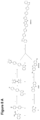
- FIG. 7 A shows the synthetic route for the preparation of a thiophen-based P material, called BDT3, according to Example 1.
- FIG. 7 B shows the MALDI-TOF Mass spectrum of BDT3 (see i), plain line: Sublimed BDT3; dotted lines, simulated mass spectrum of BDT3), TG (see ii)) and DSC (see iii)) of sublimed BDT3 and the UV-Vis absorption and PL spectra of BDT3 (see iv)).
- FIG. 8 A shows the synthetic route for the preparation of a thiophene-based P material, called BTBT14, according to Example 2.
- FIG. 8 B shows the MALDI-TOF mass spectrum of BTBT14 (see i), plain line: sublimed BTBT14; dotted lines, simulated mass spectrum of BTBT14), TG (see ii)) and DSC (see iii)) of sublimed BTBT14 and the UV-Vis absorption and PL spectra of BTBT14 (see iv)).
- FIG. 9 A shows the synthetic route for the preparation of a thiophene-based P material, called BTBT2, according to Example 3.
- FIG. 9 B shows the MALDI-TOF mass spectrum of BTBT2 (see i), plain line: sublimed BTBT2; dotted lines, simulated mass spectrum of BTBT2), TG (see ii)) and DSC (see iii)) of sublimed BTBT2 and the UV-Vis absorption and PL spectra of BTBT2 (see iv)).
- FIG. 10 A shows the synthetic route for the preparation of a thiophene-based P material, called BTBT9, according to Example 4.
- FIG. 10 B shows the MALDI-TOF mass spectrum of BTBT9 (see i), plain line: sublimed BTBT9; dotted lines, simulated mass spectrum of BTBT9), TG (see ii)) and DSC (see iii)) of sublimed BTBT9 and the UV-Vis absorption and PL spectra of BTBT9 (see iv)).
- FIG. 11 A shows the synthetic route for the preparation of a thiophene-based P material, called TT1, according to Example 6.
- FIG. 11 B shows the MALDI-TOF mass spectrum of TT1 (see i), plain line: sublimed TT1; dotted lines, simulated mass spectrum of TT1), TG (see ii)) and DSC (see iii)) of sublimed TT1 and the UV-Vis absorption and PL spectra of TT1 (see iv)).
- FIG. 12 shows the absorption coefficient for single material films BDT3, BTBT12, BTBT2, BTBT9 ( FIG. 12 A ) and TT1 ( FIG. 12 B) on glass.
- FIG. 13 shows a device structure and structure of the photoelectrical conversion layer (i-layer) according to the disclosure.
- FIG. 14 shows the absorption of BDT3:F6-OC6F5:C60 5 min/160° C. annealed: Left: Normalised absorptance of the i-layer; Right: Absorption coeffiecient of the i-layer.
- FIG. 15 shows the absorption of BTBT14:F6-OC6F5:C60 5 min/160° C. annealed: Left: Normalised absorptance of the i-layer; Right: Absorption coeffiecient of the i-layer.
- FIG. 16 shows the absorption of BTBT2:F6-OC6F5:C60 5 min/160° C. annealed: Left: Normalised absorptance of the i-layer; Right: Absorption coeffiecient of the i-layer.
- FIG. 17 shows the absorption of BTBT9:F6-OC6F5:C60 5 min/160° C. annealed: Left: Normalised absorptance of the i-layer; Right: Absorption coeffiecient of the i-layer.
- FIG. 18 shows the absorption of TT1:F6-OPh26F2:C60 5 min/160° C. annealed: Left: Normalised absorptance of the i-layer; Right: Absorption coeffiecient of the i-layer.
- FIG. 19 shows the EQE-diagram of BDT3:F6-OC6F5:C60 5 min/160° C. annealed with EQE@-2.6V with 1.6 ⁇ W/cm 2 84%.
- FIG. 20 shows the EQE-diagram of BTBT14:F6-OC6F5:C60 5 min/160° C. annealed with EQE@-2.6V with 1.6 ⁇ W/cm 2 81%.
- FIG. 21 shows the EQE-diagram of BTBT2:F6-OC6F5:C60 5 min/160° C. annealed with EQE@-2.6V with 1.6 ⁇ W/cm 2 93%.
- FIG. 22 shows the EQE-diagram of BTBT9:F6-OC6F5:C60 5 min/160° C. annealed with with p-buffer and EQE@-2.6V with 1.6 ⁇ W/cm 2 93%.
- FIG. 23 shows the EQE-diagram of TT1:F6-OPh26F2:C60 5 min/160° C. annealed with EQE@-2.6V with 1.6 ⁇ W/cm 2 61%.
- FIG. 24 shows the TDCF of BDT3:F6-OC6F5:C60 5 min/160° C. annealed; High charge generation efficiency 82% compared to deposited sample; Complete extraction of 98% at ⁇ 2.6V and 10 ⁇ s delay; Low recombination of 10% at ⁇ 2.6V and 10 ⁇ s delay.
- FIG. 25 shows the TDCF of BTBT14:F6-OC6F5:C60 5 min/160° C. annealed; Moderate charge generation efficiency of 68% compared to deposited sample; High extraction of 95% at ⁇ 2.6V and 10 ⁇ s delay; Low recombination of 11% at ⁇ 2.6V and 10 ⁇ s delay.
- FIG. 26 shows the TDCF of BTBT2:F6-OC6F5:C60 5 min/160° C. annealed; High charge generation efficiency of 81% compared to deposited sample; Moderate extraction of 65% at ⁇ 2.6V and 10 ⁇ s delay; Low recombination of 10% at ⁇ 2.6V and 10 ⁇ s delay.
- FIG. 27 shows the TDCF of BTBT9:F6-OC6F5:C60 5 min/160° C. annealed; High charge generation efficiency of 87% compared to deposited sample; Moderate extraction of 68% at ⁇ 2.6V and 10 ⁇ s delay; Low recombination of 11% at ⁇ 2.6V and 10 ⁇ s delay.
- FIG. 28 shows the TDCF of TT1:F6-OPh26F2:C60 5 min/160° C. annealed; High charge generation efficiency of 64% compared to deposited sample; Moderate extraction of 96% at ⁇ 2.6V and 10 ⁇ s delay; Low recombination of 21% at ⁇ 2.6V and 10 ⁇ s delay.
- FIG. 29 shows the response/photocurrent decay: fast components of normalised current: highest for BDT3; Shortest photocurrent decay.
- FIG. 30 shows the response/photocurrent decay: Longer photocurrent decay for dimers.
- FIG. 31 shows results for BDT3 (subl):F6OC6F5:C60 (4:4:2): action spectrum (i), IV (ii) and EQE (iii).
- p-buffer EQE@-2.5V with 1.6 ⁇ W/cm2 84%.
- FIG. 32 shows the response/photocurrent decay: BDT3:F6OC6F5:C60 4:4:2: fast components of normalised current: highest for BDT3; Shortest photocurrent decay.
- the present disclosure provides a transparent P material.
- the transparent P material according to the present disclosure has the quality when comprised in a P:N heterojunction or P:N bilayer or multilayer junction, particularly a P:N1:N2 or a P1:P2:N heterojunction or multilayer junction, to dissociate efficiently the excitons created in colored N, or in a mixture of colored N materials (N1:N2), or in another colored P or in a mixture of colored P and N materials (P2:N) via a process of HOMO dissociation. It might also have the quality to further transport the holes.
- the transparent P material donates electron into the HOMO of the excited colored material (the P material(s) or the N material(s) absorbing photons), which is equivalent to accepting a hole.
- “transparent” refers to an extinction coefficient of less than about 60,000 M ⁇ 1 cm ⁇ 1 in the visible wavelength range in the region of about 450 to about 700 nm and to an extinction coefficient of less than about 100,000 M ⁇ 1 cm ⁇ 1 in the visible wavelength range in the region of about 400 to about 450 nm, or to an absorption coefficient (in single material film) of less than 70,000 cm ⁇ 1 for wavelengths longer than 450 nm, or to an absorption coefficient (in single material film) of less than 40,000 cm ⁇ 1 for wavelengths longer than 500 nm
- “colored” refers to an absorption coefficient of more than about 60,000 cm ⁇ 1 in the visible wavelength range in the region from about 400 nm to about 700 nm (with maxima anywhere in this region or absorbing everywhere in this region).
- the transparent P material of the present disclosure is transparent to visible light.
- the transparent P material has an absorption coefficient (in single material film) of less than 70,000 cm ⁇ 1 for wavelengths longer than 450 nm, or an absorption coeffiecient (in single material film) of less than 40,000 cm ⁇ 1 for wavelengths longer than 500 nm.
- the transparent P material of the present disclosure is selected from the group of
- the transparent P material of the present disclosure is a thiophene- or selenophene-based material represented by the general formula IX
- X and Y are the same or different and are, at each occurrence, independently selected from CR 2 , S, O, Se, N—R and Si—R 2 , wherein R 2 is selected from H, CH 3 , CF 3 , phenyl, alkyl and aryl, and R is selected from H, linear and branched alkyl group, cycloalkyl group, linear and branched alkoxy group, halogenated alkyl group, halogen atoms, alkyl or aryl sulfanyl group, alkyl or aryl amine, aryl group, halogenated aryl group, biaryl group, halogenated alkyl group, heteroaryl group and fluorenyl group.
- X and Y are the same or different and are, at each occurrence, independently selected from S and Se.
- R is selected from
- R 4 , R 5 , R 6 are the same or different and are, at each occurrence, independently selected from H, F, CH 3 , CF 3 , aryl and alkyl.
- X and Y are the same or different and are, at each occurrence, independently selected from S and Se, and
- R is selected from
- R 4 , R 5 , R 6 are the same or different and are, at each occurrence, independently selected from H, F, CH 3 , CF 3 , aryl and alkyl.
- the material is selected from the group consisting of
- the transparent P material of the present disclosure is a thiophene- or selenophene-based material represented by the general formula Xa
- X and Y are the same or different and are, at each occurrence, independently selected from CR 2 , S, O, Se, N—R and Si—R 2 , wherein R 2 is selected from H, CH 3 , CF 3 , phenyl, alkyl and aryl; and R is selected from H, linear and branched alkyl group, cycloalkyl group, linear and branched alkoxy group, halogenated alkyl group, halogen atoms, alkyl or aryl sulfanyl group, alkyl or aryl amine, aryl group, halogenated aryl group, biaryl group, halogenated alkyl group, heteroaryl group and fluorenyl group.
- X and Y are the same or different and are, at each occurrence, independently selected from S and Se.
- R is selected from
- R 4 , R 5 , R 6 are the same or different and are, at each occurrence, independently selected from H, F, CH 3 , CF 3 , aryl and alkyl.
- X and Y are the same or different and are, at each occurrence, independently selected from S and Se;
- R is selected from
- R 4 , R 5 , R 6 are the same or different and are, at each occurrence, independently selected from H, F, CH 3 , CF 3 , aryl and alkyl.
- the material is selected from the group consisting of
- the transparent P material of the present disclosure is a thiophene- or selenophene-based material represented by the general formula Xb
- X and Y are the same or different and are independently, at each occurrence, selected from CR 2 , S, O, Se, N—R and Si—R 2 , wherein R 2 is selected from H, CH 3 , CF 3 , phenyl, alkyl and aryl; and R is selected from H, linear and branched alkyl group, cycloalkyl group, linear and branched alkoxy group, halogenated alkyl group, halogen atoms, alkyl or aryl sulfanyl group, alkyl or aryl amine, aryl group, halogenated aryl group, biaryl group, halogenated alkyl group, heteroaryl group and fluorenyl group.
- X and Y are the same or different and are, at each occurrence, independently selected from S and Se.
- R is selected from
- R 4 , R 5 , R 6 are the same or different and are, at each occurrence, independently selected from H, F, CH 3 , CF 3 , aryl and alkyl.
- X and Y are the same or different and are, at each occurrence, independently selected from S and Se;
- R is selected from
- R 4 , R 5 , R 6 are the same or different and are, at each occurrence, independently selected from H, F, CH 3 , CF 3 , aryl and alkyl.
- the material is selected from the group consisting of
- the transparent P material of the present disclosure is a thiophene- or selenophene-based material represented by the general formula XXXIa and XXXIb
- X and Y are the same or different and are, at each occurrence, independently selected from CR 2 , S, O, Se, N—R and Si—R 2 , wherein R 2 is selected from H, CH 3 , CF 3 , phenyl, alkyl and aryl; and R is selected from H, linear and branched alkyl group, cycloalkyl group, linear and branched alkoxy group, halogenated alkyl group, halogen atoms, alkyl or aryl sulfanyl group, alkyl or aryl amine, aryl group, halogenated aryl group, biaryl group, halogenated alkyl group, heteroaryl group and fluorenyl group.
- X and Y are the same or different and are, at each occurrence, independently selected from S and Se.
- R is selected from
- R 4 , R 5 , R 6 are the same or different and are, at each occurrence, independently selected from H, F, CH 3 , CF 3 , aryl and alkyl.
- X and Y are the same or different and are, at each occurrence, independently selected from S and Se;
- R is selected from
- R 4 , R 5 , R 6 are the same or different and are, at each occurrence, independently selected from H, F, CH 3 , CF 3 , aryl and alkyl.
- the material is selected from the group consisting of
- the transparent P material of the present disclosure is a thiophene- or selenophene-based material represented by the general formula XXXIX, T-B-T XXXIX, wherein, T is selected from a structure with one of the general formulas IX, Xa, Xb, XI, XIIa, XIIb, XXII to XXXVIII:
- X and Y are the same or different and are, at each occurrence, independently selected from CR 2 , S, O, Se, N—R and Si—R 2 , wherein R 2 is selected from H, CH 3 , CF 3 , aryl and alkyl, and, R and R 1 are the same or different and are, at each occurrence, independently selected from H, linear and branched alkyl group, cycloalkyl group, linear and branched alkoxy group, halogenated alkyl group, halogen atoms, alkyl or aryl sulfanyl group, alkyl or aryl amine, aryl group, halogenated aryl group, biaryl group, halogenated alkyl group, heteroaryl group and fluorenyl group; and B is selected from none,
- R 3 selected from
- the material is selected from the group consisting of
- the transparent P material of the present disclosure is a thiophene- or selenophene-based material represented by the general formula XL T-H XL, T is selected from a structure with one of the general formulas IX, Xa, Xb, XI, XIIa, XXII to XXXVIII:
- R 4 , R 5 , R 6 are the same or different and are, at each occurrence, independently selected from H, F, CH 3 , alkyl group and aryl group.
- the material is selected from the group consisting of
- the transparent P material of the present disclosure is a thiophene- or selenophene-based material represented by the general formula XLI, H-T-B-T-H XLI, wherein, T is none or selected from a structure with one of the general formulas IX, Xa, Xb, XI, XIIa, XIIb, XXII to XXXVIII:
- X and Y are the same or different and are, at each occurrence, independently selected from CR 2 , S, O, Se, N—R and Si—R 2 , wherein R 2 is selected from H, CH 3 , CF 3 , phenyl, alkyl and aryl; and R and R 1 are the same or different and are, at each occurrence, independently selected from H, linear and branched alkyl group, cycloalkyl group, linear and branched alkoxy group, halogenated alkyl group, halogen atoms, alkyl or aryl sulfanyl group, alkyl or aryl amine, aryl group, halogenated aryl group, biaryl group, halogenated alkyl group, heteroaryl group and fluorenyl group; B is selected from none
- R 7 selected from H, alkyl group, aryl group or halogen and n being 0 to 6
- R 4 , R 5 , R 6 are the same or different and are, at each occurrence, independently selected from H, F, CH 3 , alkyl and aryl.
- the material is selected from the group consisting of
- the material is a thiophene-based material selected from the group of BDT3, BTBT14, BTBT2, BTBT9 and TT1:
- the present disclosure provides a P:N heterojunction, preferably a heterojunction, including a transparent P material according to the present disclosure.
- a transparent P material according to the present disclosure is the donor and a transparent N material is the acceptor in a P:N heterojunction. See, for example, FIG. 4 .
- one of the P materials could be a transparent P material according to the present disclosure and a donor.
- the P:N heterojunction preferably the P:N1:N2 heterojunction includes a N and/or a further P material,
- N and/or further P material preferably exhibits absorption in the visible wavelength range (about 400 to about 700 nm).
- the present disclosure provides the use of a transparent P material according to the present disclosure in an absorption layer.
- the absorption layer includes a further N and/or P material
- the further N and/or P material preferably exhibits absorption in the visible wavelength range (about 400 to about 700 nm).
- the present disclosure provides the use of a transparent P material according to the present disclosure
- the photoelectric conversion layer and/or the organic and/or hybrid module includes a N and/or a further P material
- N and/or further P material preferably exhibits absorption in the visible wavelength range (about 400 to about 700 nm).
- the present disclosure provides a photoelectric conversion layer comprising a transparent P material according to the present disclosure.
- the photoelectric conversion layer comprises an N and/or further P material, wherein the N and/or further P material preferably exhibits absorption in the visible wavelength range (about 400 to about 700 nm).
- the photoelectric conversion layer comprises further molecule(s).
- the present disclosure provides an absorption layer comprising a transparent P material according to the present disclosure.
- the absorption layer includes an N and/or further P material, wherein the N and/or further P material preferably exhibits absorption in the visible wavelength range (about 400 to about 700 nm).
- the absorption layer comprises further molecule(s).
- the present disclosure provides a device, including transparent P material(s) according to the present disclosure or photoelectric conversion layer(s) according to the present disclosure.
- Said device can be an organic image sensor, a hybrid image sensor, photodiode, organic photovoltaics, organic light-emitting diode (OLED), organic thin-film transistor (OTFT).
- OLED organic light-emitting diode
- OTFT organic thin-film transistor
- said photoelectric conversion layer exhibits photo response in the visible absorption range.
- the photoelectric conversion layer of the device includes the transparent P material(s) according to the present disclosure and an N and/or further P material(s), preferably exhibiting absorption in the visible wavelength range (about 400 to about 700 nm).
- the photoelectric conversion layer of the device includes further molecule(s).
- the photoelectric conversion layer can include different components (dyes) and combinations thereof.
- the photoelectric conversion layer and/or the absorption layer includes further n and p type materials (molecules) and their derivatives that can be used together with the material(s) of the present disclosure, such as phthalocyanines (Pc), subphthalocyanines (SubPc), merocyanines (MC), diketopyrrolopyrroles (DPP), borondipyrromethenes (BODIPY), isoindigo (ID), perylenediimides (PDI) and perylenemonoimides (PMI), and quinacridones (QD), fused acenes, such as pentacene and tetracene and triphenylamine and its derivatives (TPAs) as donor;
- phthalocyanines Pc
- SubPc subphthalocyanines
- MC merocyanines
- DPP diketopyrrolopyrroles
- BODIPY borondipyrromethenes
- ID isoindigo
- PDI perylenediimi
- fullerenes rylenediimides and monoimides (e.g. PDI and PMIs but not limited to), phthalocyanines and subphthalocyanines, borondipyrromethenes (BODIPY)and cyanopentacenes as acceptor.
- rylenediimides and monoimides e.g. PDI and PMIs but not limited to
- phthalocyanines and subphthalocyanines e.g. PDI and PMIs but not limited to
- BODIPY borondipyrromethenes
- the present disclosure provides an organic image sensor, including photoelectric conversion layer(s) according to the present disclosure.
- the organic image sensor of the present disclosure preferably includes
- the substrate can be silicon, quartz, glass, polymer, such as PMMA, PC, PS, COP, COP, PVA, PVP, PES, PET,PEN, mica, or combinations thereof.
- the substrate can also be other photoelectric conversion unit(s).
- a device of this disclosure can include (i) two inorganic units with one organic unit, (ii) one inorganic unit with two organic units, or (iii) three organic units combined with each other in the organic image sensor. Any of the organic units can contain molecules/layers/devices according to this disclosure.
- an organic image sensor consists of three organic conversion units containing molecules in layers as of this disclosure (in devices, each with transparent electrodes), combined with each other and operating each in one of the ranges 400 nm to 500 nm, 500 nm to 600 nm and 600 nm to 700 nm.
- Combined units can be realized either by vertical and/or horizontal stacking of the organic-organic or organic-inorganic units.
- the electrode material can be any organic compound.
- the present disclosure provides a hybrid Silicon-organic image sensor or organic image sensor, including
- said organic photoelectric conversion unit of the image sensors of the present disclosure includes different layers within the organic based photoelectrical conversion unit(s), such as
- the organic image sensor of the present disclosure can have the structure:
- the organic image sensor of the present disclosure can include different layer structures, in particular regarding the position of the n and p material with respect to the CMOS part.
- the organic photoconversion unit can be used in combination with a Si based photoelectrical conversion unit where different layers absorb different color (BGR) in a hybrid silicon-organic image sensor (see FIG. 2 ) or can be used without Si based photoelectrical conversion unit. In this case the organic photoconversion unit has the capability of absorbing different color (BGR).
- the BGR ranges are 400-500 nm, 500-600 nm and 600-700 nm and the absorption outside of the range is preferably less than 25%, more preferably less than 20%, even more preferably less than 10 and 5%.
- the substrate can also be other photoelectric conversion unit(s).
- a device of this disclosure can include (i) two inorganic units with one organic unit, (ii) one inorganic unit with two organic units, or (iii) three organic units combined with each other in the organic image sensor. Any of the organic units can contain molecules/layers/devices according to this disclosure.
- the deposition methods to produce the organic photoelectrical conversion layer are PVD, CVD, spin coating, dipping coating, casting process, inkjet printing, screen printing, spray coating, offset printing.
- Different process temperatures for processing the layer are possible, namely from 50 to 245° Celsius.
- the processing (annealing) of the layers can be done before and/or after the deposition of the top electrode.
- the present disclosure provides a method for synthesis of thiophene- or selenophene-based materials (represented by a general formula IX) comprising the steps of
- the present disclosure provides also a method for synthesis of thiophene- or selenophene-based materials (represented by a general formula Xb) comprising the steps of
- the present disclosure provides also a method for synthesis of thiophene- or selenophene-based material (represented by a general formula XXXI) comprising the steps of
- the present disclosure provides also a method for synthesis of thiophene- or selenophene-based material (represented by a general formula XXXIX) comprising the steps of a) reaction of chlorobenzaldehyde with sodium hydrogensulfide hydrate and bromination with elemental bromine;
- X and Y are the same or different and are, at each occurrence, independently selected from CR 2 , S, O, Se, N—R and Si—R 2 , wherein R 2 is selected from H, CH 3 , CF 3 , phenyl, alkyl and aryl, and R is selected from H, linear and branched alkyl group, cycloalkyl group, linear and branched alkoxy group, halogenated alkyl group, halogen atoms, alkyl or aryl sulfanyl group, alkyl or aryl amine, aryl group, halogenated aryl group, biaryl group, halogenated alkyl group, heteroaryl group and fluorenyl group.
- R 2 is selected from H, CH 3 , CF 3 , phenyl, alkyl and aryl
- R is selected from H, linear and branched alkyl group, cycloalkyl group, linear and branched alkoxy group
- X and Y are the same or different and are, at each occurrence, independently selected from S and Se, and/or R is selected from
- R 4 , R 5 , R 6 are the same or different and are, at each occurrence, independently selected from H, F, CH 3 , CF 3 , aryl and alkyl.
- X and Y are the same or different and are, at each occurrence, independently selected from CR 2 , S, O, Se, N—R and Si—R 2 , wherein R 2 is selected from H, CH 3 , CF 3 , phenyl, alkyl and aryl; and R is selected from H, linear and branched alkyl group, cycloalkyl group, linear and branched alkoxy group, halogenated alkyl group, halogen atoms, alkyl or aryl sulfanyl group, alkyl or aryl amine, aryl group, halogenated aryl group, biaryl group, halogenated alkyl group, heteroaryl group and fluorenyl group.
- X and Y are the same or different and are, at each occurrence, independently selected from S and Se, and/or R is selected from
- R 4 , R 5 , R 6 are the same or different and are, at each occurrence, independently selected from H, F, CH 3 , CF 3 , aryl and alkyl.
- X and Y are the same or different and are independently, at each occurrence, selected from CR 2 , S, O, Se, N—R and Si—R 2 , wherein R 2 is selected from H, CH 3 , CF 3 , phenyl, alkyl and aryl; and R is selected from H, linear and branched alkyl group, cycloalkyl group, linear and branched alkoxy group, halogenated alkyl group, halogen atoms, alkyl or aryl sulfanyl group, alkyl or aryl amine, aryl group, halogenated aryl group, biaryl group, halogenated alkyl group, heteroaryl group and fluorenyl group.
- X and Y are the same or different and are, at each occurrence, independently selected from S and Se, and/or R is selected from
- R 4 , R 5 , R 6 are the same or different and are, at each occurrence, independently selected from H, F, CH 3 , CF 3 , aryl and alkyl.
- X and Y are the same or different and are, at each occurrence, independently selected from CR 2 , S, O, Se, N—R and Si—R 2 , wherein R 2 is selected from H, CH 3 , CF 3 , phenyl, alkyl and aryl; and R is selected from H, linear and branched alkyl group, cycloalkyl group, linear and branched alkoxy group, halogenated alkyl group, halogen atoms, alkyl or aryl sulfanyl group, alkyl or aryl amine, aryl group, halogenated aryl group, biaryl group, halogenated alkyl group, heteroaryl group and fluorenyl group.
- X and Y are the same or different and are, at each occurrence, independently selected from S and Se, and/or R is selected from
- R 4 , R 5 , R 6 are the same or different and are, at each occurrence, independently selected from H, F, CH 3 , CF 3 , aryl and alkyl.
- the transparent P material of (3) wherein the material is a thiophene- or selenophene-based material represented by the general formula XXXIX, T-B-T XXXIX, wherein, T is selected from a structure with one of the general formulas IX, Xa, Xb, XI, XIIa, XIIb, XXII to XXXVIII:
- R 3 selected from
- R 7 selected from
- H alkyl group, aryl group or halogen and n being 0 to 6, H is selected from
- R 4 , R 5 , R 6 are the same or different and are, at each occurrence, independently selected from H, F, CH 3 , alkyl and aryl.
- a transparent P material according to any of (1) to (15) in a photoelectric conversion layer and/or in an organic and/or hybrid module for optoelectronic application such as image sensor, photodiode, organic photovoltaics, comprising organic photoelectric conversion layer(s), OLED and OTFT organic modules, and comprising a N and/or a further P material, wherein the N and/or further P material particularly exhibits absorption in the visible wavelength range (about 400 to about 700 nm).
- a photoelectric conversion layer comprising a transparent P material according to any one of (1) to (15), and comprising a N and/or further P material, wherein the N and/or further P material particularly exhibits absorption in the visible wavelength range (about 400 to about 700 nm).
- An absorption layer comprising a transparent P material according to any one of (1) to (15), and comprising a N and/or further P material, and optionall comprising further molecule(s). wherein the N and/or further P material particularly exhibits absorption in the visible wavelength range (about 400 to about 700 nm).
- a device comprising transparent P material(s) according to any one of (1) to (15) or photoelectric conversion layer(s) according to (19), wherein said device is particularly an organic image sensor, an hybrid image sensor, photodiode, organic photovoltaics, organic light-emitting diode (OLED), organic thin-film transistor (OTFT).
- An organic image sensor comprising (a) anorganic photoelectric conversion unit comprising photoelectric conversion layer(s) according to (19), (b) at least one electrode, (c) a substrate, (d) optionally, a second electrode on top of said photoelectric conversion layer(s).
- a hybrid Silicon-organic image sensor or organic image sensor comprising (a) anorganic photoelectric conversion unit or units comprising photoelectric conversion layer(s) according to (19), (b) optionally, a Si based photoelectric conversion unit, (c) metal wiring, (d) a (CMOS) substrate, (e) insulating layer(s), particularly oxide.
- CMOS complementary metal-oxide-semiconductor
- insulating layer(s) particularly oxide.
- a method for synthesis of thiophene- or selenophene-based materials comprising the steps of a) palladium- and SPhos-system catalyzed Suzuki coupling of the specific R-boronic acid and subsequent borylation with bis(pinacolato)diboron in palladium catalyst system; b) parallel reaction of chlorobenzaldehyde with sodium hydrogensulfide hydrate and bromination with elemental bromine; c) palladium- and SPhos-system catalyzed Suzuki coupling of product of a) and the product of b).
- a method for synthesis of thiophene- or selenophene-based materials comprising the steps of a) palladium- and SPhos system catalyzed Suzuki coupling of the specific R-dibromide; b) palladium- and SPhos system catalyzed Suzuki coupling of two equivalents of the product of a) with specific Xb-diboronic ester.
- a method for synthesis of thiophene- or selenophene-based material comprising the steps of a) reaction of chlorobenzaldehyde with sodium hydrogensulfide hydrate and bromination with elemental bromine; b) palladium catalyzed reaction of T-specific benzothiophene with B-specific diboronic acid.
- a method for synthesis of thiopheen- or selenophene-based material comprising the steps of a) reaction of chlorobenzaldehyde with sodium hydrogensulfide hydrate and bromination with elemental bromine; b) palladium catalyzed reaction of T-specific benzothiophene with B-specific diboronic acid.
- N material refers to a material accepting an electron.
- P material refers to a material donating an electron, which is the same as accepting a hole. It might also transport holes.
- thiophene material or “thiophene-based material”, as used herein, refers to a molecule in which at least a thiophene or a thiophene derivative is present in the molecular structure.
- selenophene material or “selenophene-based material”, as used herein, refers to a molecule in which at least a selenophene or a selenophene derivative is present in the molecular structure.
- a molecule may only absorb in the range of from 500-700 nm, whereas another molecule may absorb in the range of from 400-700 nm or 500-600 nm, whereas a third molecule may absorb over the range of from 400-500 nm (or the above described sub-ranges of preferably 400 nm to 500 nm, or 500 nm to 600 nm, or 600 nm to 700 nm). All these scenarios are meant to be encompassed by such wording.
- narrow absorption band is meant to refer to/means that the width of the absorption band at 50% intensity is 200 nm, more preferably 150 nm, more preferably 100 nm.
- transparent refers to a material having an extinction coefficient of less than about 60,000 M ⁇ 1 cm ⁇ 1 in the visible wavelength range in the region of about 450 to about 700 nm and to an extinction coefficient of less than about 100,000 M ⁇ 1 cm ⁇ 1 in the visible wavelength range in the region of about 400 to about 450 nm.
- colored refers to a material having an absorption coefficient of more than about 60,000 cm ⁇ 1 in the visible wavelength range in the region from about 400 nm to about 700 nm (with maxima anywhere in this region or absorbing everywhere in this region).
- Electrode refers to an electrical lead to apply voltage.
- An electrode may be “interdigitated”, meaning that it has a comb-like shape with two combs lying opposite each other and the respective figures of the combs engaging with each other.
- an electrode may be a non-interdigitated.
- An electrode may be transparent or non-transparent.
- a transparent electrode may, for example, be formed from indium tin oxide (ITO) or from fluorinated tin oxide (FTO).
- a non-transparent electrode may be reflective and may, for example, be formed from silver (Ag) or gold (Au).
- the present inventors have found—for the use as active materials for the organic photoconversion unit—material of specific structure which show no or very low absoption in the visible range (400 to 650 nm), belonging to the following different families:
- Said materials are used in a bulk heterojunction (mixed p-n layer) or PN heterojunction (formed between a p layer and n layer) or PiN junction (p layer—mixed layer as p-n bulk heterojunction—n-layer) in the photoelectric conversion material layer together with a material that absorbs in the visible range.
- the materials of the present disclosure can be used as active materials for the organic photoconversion unit.
- the organic photoconversion unit can be used in combination with a Si based photoelectrical conversion unit where different layer absorbe different colour (BGR) in a hybrid Silicon-organic image sensor or can be used without Si based photoelectrical conversion unit. In this case, the organic photoconversion unit having the capability of absorbing different colour (BGR).
- the general structure of the resulting hybrid image sensor device as well as the details of the organic based photoelectrical conversion unit are schematic represented in the FIGS. 2 and 3 .
- the P material is transparent and the N material the colored one (as e.g. shown in FIG. 4 ).
- the N material the colored one (as e.g. shown in FIG. 4 ).
- one of the N materials could be colored or one (as in FIG. 5 ), or both of them could be colored.
- P1:P2:N P2 can be transparent or colored, and N could be transparent or colored.
- ⁇ CT has ⁇ CT(HOMO) and ⁇ CT(LUMO) parts
- the energy levels and the morphology in thin film are tunable by the type of substituents R and R 1 as well as the heteroatoms in the core structure. This makes the thiophene based molecules very versatile molecules to be used in the organic photoelectric conversion layer in combination with a material that absorbs in the visible range.
- 3-(4-Bromobiphenyl)-benzothiophene (3) was prepared by a chemoselective SUZUKI-type cross coupling of the benzothiophene-3-boronic acid (1) and 4-Iodo-4′-bromo-biphenyl (2).
- Using the SPhos catalyst system in 1,4-Dioxane at room temperature (i) gave the target compound in moderate yields (64%).
- the same catalyst was used for the synthesis of BDT3 by coupling two equivalents (3) to the BDT-diboronic ester (4), the reaction was run at 105° C. for 20 h (ii). The structure has been confirmed by MALDI-TOF Mass Spectrometry (see FIG. 7 B, i)).
- the BDT3 has excellent thermal stability (T decomp >480° C.), and according to DSC, undergoes phase transition at 451° C. and 459° C. in the heating cycle and at 455° C. and 421° C. in the cooling cycle (see FIG. 7 B, ii)).
- UV-Vis absorption and PL spectra of BDT3 were recorded from thermally evaporated thin films and are given in FIG. 7 B, iii) and iv).
- 3-(4-Bromobiphenyl)-benzothiophene (3) was prepared by a chemoselective SUZUKI-type cross coupling of the benzothiophene-3-boronic acid (1) and 4-iodo-4′-bromo-biphenyl (2).
- Using the SPhos catalyst system in 1,4-Dioxane at room temperature (i) gave the target compound in moderate yields (64%).
- the borilation of (3) was done using bis(pinacolato)diboron in the 1,1′-bis(diphenylphosphino)-ferrocene dichloropalladium catalyst system in 1,4-Dioxane at 100° C.
- the BTBT core building block was received by reaction of chlorobenzaldehyde with sodium hydrogensulfide hydrate at high temperature in NMP (iii). Bromination of BTBT was carried out using elemental bromine in DCM (iv). The same catalyst used in (i) was used for the synthesis of BTBT14 by coupling two equivalents 5 to the BTBT-Br, the reaction was run at 90° C. for 16 h (v). The structure has been confirmed by MALDI-TOF Mass Spectrometry (see FIG. 8 B, i)).
- the BTBT14 has excellent thermal stability (T decomp >500° C.), and according to DSC, undergoes phase transition at 395° C. in the heating cycle and at 384° C.
- UV-Vis absorption and PL spectra of BTBT14 were recorded from thermally evaporated thin films and are given in FIG. 8 B, iii) and iv).
- the BTBT core building block was received by reaction of chlorobenzaldehyde with sodium hydrogensulfide hydrate at high temperature in NMP.
- Bromination of BTBT was carried out using elemental bromine in DCM.
- the final reaction to obtained BTBT2 was done using a mixture of 2-bromo-[1]benzothieno[3,2-b][1]benzothiophene (3) and 4,4′-biphenyldiboronic acid (4), potassium carbonate and Pd(PPh 3 ) 4 in water and at 80° C. overnight under inert atmosphere. Structure was confirmed by MALDI-TOF Mass Spectrometry (see FIG. 9 B, i)).
- the BTBT2 has excellent thermal stability (T decomp >460° C.), and according to DSC, do not showed phase transition till at 460° C. in the heating in the cooling cycle (see FIG. 9 B, ii)).
- UV-Vis absorption and PL spectra of BTBT2 were recorded from thermally evaporated thin films and are given in FIG. 9 B, iii) and iv).
- the BTBT9 material can be obtained in convergent three step synthesis starting from phenthrene (1) that is brominated and then converted in diboronic ester (3) using MIYAURA borylation. In the last step 3 is reacted with 2.2 equivalents of BTBT-Br in a SUZUKI-type cross coupling reaction to give the desired product BTBT9. Structure was confirmed by MALDI-TOF Mass Spectrometry (see FIG. 10 B, i)).
- the BTBT9 has excellent thermal stability (T decomp >500° C.), and according to DSC, undergoes phase transition at 454° C. in the heating cycle and at 437° C. in the cooling cycle ( FIG. 10 B, ii)).
- 3-(4-Bromobiphenyl)-benzothiophene (3) was prepared by a chemoselective SUZUKI-type cross coupling of the benzothiophene-3-boronic acid (1) and 4-Iodo-4′-bromo-biphenyl (2).
- Using the SPhos catalyst system in 1,4-Dioxane at room temperature (i) gave the target compound in moderate yields (64%).
- TT1 was prepared by STILLE-type cross coupling using tetrakis(triphenylphosphine)palladium(0) to react two equivalents of 3 with 2,5-bis(trimethylstannyl)thieno[3,2-b]thiophene (4). The reaction was run at 105° C.
- the structure has been confirmed by MALDI-TOF Mass Spectrometry (see FIG. 11 B, i)).
- the TT1 has excellent thermal stability (T decomp >490° C.), and according to DSC, undergoes phase transition at 426° C. in the heating cycle and at 407° C. in the cooling cycle ( FIG. 11 B, ii) and iii)).
- UV-Vis absorption and PL spectra of TT1 were recorded form thermally evaporated thin films and are given in FIG. 11 B iv).
- the device properties for devices with photoelectrical conversion layer as shown in FIG. 13 and the different molecules described in the Examples 1 to 5 as p-material are shown in FIGS. 14 to 32 .
Abstract
Description
-
- an extinction coefficient of less than about 60,000 M−1 cm−1 in the visible wavelength range in the region of about 450 to about 700 nm and to an extinction coefficient of less than about 100,000 M−1 cm−1 in the visible wavelength range in the region of about 400 to about 450 nm, or
- an absorption coefficient (in single material film) of less than 70,000 cm−1 for wavelengths longer than 450 nm, or
- an absorption coeffiecient (in single material film) of less than 40,000 cm−1 for wavelengths longer than 500 nm, and
-
- is an organic based compound forming high quality homogenous films when using deposition methods (such as vacuum deposition or spincoating)
- has an extinction coefficient of less than about 60,000 M−1 cm−1 in the visible wavelength range in the region of about 450 to about 700 nm and an extinction coefficient of less than about 100,000 M−1 cm−1 in the visible wavelength range in the region of about 400 to about 450 nm,
and - is an organic based compound forming high quality homogenous films when using deposition methods (such as vacuum deposition or spincoating),
- has an absorption coefficient (in single material film) of less than 70,000 cm−1 for wavelengths longer than 450 nm, or
- an absorption coeffiecient (in single material film) of less than 40,000 cm−1 for wavelengths longer than 500 nm.
-
- is an organic based compound forming high quality homogenous films when using deposition methods (such as vacuum deposition or spincoating),
- has an extinction coefficient of less than about 60,000 M−1 cm−1 in the visible wavelength range in the region of about 450 to about 700 nm and an extinction coefficient of less than about 100,000 M−1 cm−1 in the visible wavelength range in the region of about 400 to about 450 nm.
-
- thiophene-based materials,
- selenophene-based material, and
- dimers thereof.

wherein,
X and Y are the same or different and are, at each occurrence, independently selected from CR2, S, O, Se, N—R and Si—R2, wherein R2 is selected from H, CH3, CF3, phenyl, alkyl and aryl, and
R is selected from H, linear and branched alkyl group, cycloalkyl group, linear and branched alkoxy group, halogenated alkyl group, halogen atoms, alkyl or aryl sulfanyl group, alkyl or aryl amine, aryl group, halogenated aryl group, biaryl group, halogenated alkyl group, heteroaryl group and fluorenyl group.


wherein R4, R5, R6 are the same or different and are, at each occurrence, independently selected from H, F, CH3, CF3, aryl and alkyl.


wherein R4, R5, R6 are the same or different and are, at each occurrence, independently selected from H, F, CH3, CF3, aryl and alkyl.


wherein,
X and Y are the same or different and are, at each occurrence, independently selected from CR2, S, O, Se, N—R and Si—R2, wherein R2 is selected from H, CH3, CF3, phenyl, alkyl and aryl; and
R is selected from H, linear and branched alkyl group, cycloalkyl group, linear and branched alkoxy group, halogenated alkyl group, halogen atoms, alkyl or aryl sulfanyl group, alkyl or aryl amine, aryl group, halogenated aryl group, biaryl group, halogenated alkyl group, heteroaryl group and fluorenyl group.


wherein R4, R5, R6 are the same or different and are, at each occurrence, independently selected from H, F, CH3, CF3, aryl and alkyl.


wherein R4, R5, R6 are the same or different and are, at each occurrence, independently selected from H, F, CH3, CF3, aryl and alkyl.


wherein,
X and Y are the same or different and are independently, at each occurrence, selected from CR2, S, O, Se, N—R and Si—R2, wherein R2 is selected from H, CH3, CF3, phenyl, alkyl and aryl; and
R is selected from H, linear and branched alkyl group, cycloalkyl group, linear and branched alkoxy group, halogenated alkyl group, halogen atoms, alkyl or aryl sulfanyl group, alkyl or aryl amine, aryl group, halogenated aryl group, biaryl group, halogenated alkyl group, heteroaryl group and fluorenyl group.


wherein R4, R5, R6 are the same or different and are, at each occurrence, independently selected from H, F, CH3, CF3, aryl and alkyl.


wherein R4, R5, R6 are the same or different and are, at each occurrence, independently selected from H, F, CH3, CF3, aryl and alkyl.


wherein,
X and Y are the same or different and are, at each occurrence, independently selected from CR2, S, O, Se, N—R and Si—R2, wherein R2 is selected from H, CH3, CF3, phenyl, alkyl and aryl; and
R is selected from H, linear and branched alkyl group, cycloalkyl group, linear and branched alkoxy group, halogenated alkyl group, halogen atoms, alkyl or aryl sulfanyl group, alkyl or aryl amine, aryl group, halogenated aryl group, biaryl group, halogenated alkyl group, heteroaryl group and fluorenyl group.


wherein R4, R5, R6 are the same or different and are, at each occurrence, independently selected from H, F, CH3, CF3, aryl and alkyl.


wherein R4, R5, R6 are the same or different and are, at each occurrence, independently selected from H, F, CH3, CF3, aryl and alkyl.


T-B-T XXXIX,
wherein,
T is selected from a structure with one of the general formulas IX, Xa, Xb, XI, XIIa, XIIb, XXII to XXXVIII:


X and Y are the same or different and are, at each occurrence, independently selected from CR2, S, O, Se, N—R and Si—R2, wherein R2 is selected from H, CH3, CF3, aryl and alkyl, and,
R and R1 are the same or different and are, at each occurrence, independently selected from H, linear and branched alkyl group, cycloalkyl group, linear and branched alkoxy group, halogenated alkyl group, halogen atoms, alkyl or aryl sulfanyl group, alkyl or aryl amine, aryl group, halogenated aryl group, biaryl group, halogenated alkyl group, heteroaryl group and fluorenyl group; and
B is selected from none,


with R3 selected from


H, alkyl group, aryl group or halogen and n being 0 to 6,


T-H XL,
T is selected from a structure with one of the general formulas IX, Xa, Xb, XI, XIIa, XXII to XXXVIII:


wherein,
X and Y are the same or different and are, at each occurrence, independently selected from CR2, S, O, Se, N—R and Si—R2, wherein R2 is selected from H, CH3, CF3, phenyl, alkyl and aryl;
R and R1 are the same or different and are, at each occurrence, independently selected from H, linear and branched alkyl group, cycloalkyl group, linear and branched alkoxy group, halogenated alkyl group, halogen atoms, alkyl or aryl sulfanyl group, alkyl or aryl amine, aryl group, halogenated aryl group, biaryl group, halogenated alkyl group, heteroaryl group and fluorenyl group, and
H is selected from any one of


wherein R4, R5, R6 are the same or different and are, at each occurrence, independently selected from H, F, CH3, alkyl group and aryl group.


H-T-B-T-H XLI,
wherein,
T is none or selected from a structure with one of the general formulas IX, Xa, Xb, XI, XIIa, XIIb, XXII to XXXVIII:


wherein,
X and Y are the same or different and are, at each occurrence, independently selected from CR2, S, O, Se, N—R and Si—R2, wherein R2 is selected from H, CH3, CF3, phenyl, alkyl and aryl; and
R and R1 are the same or different and are, at each occurrence, independently selected from H, linear and branched alkyl group, cycloalkyl group, linear and branched alkoxy group, halogenated alkyl group, halogen atoms, alkyl or aryl sulfanyl group, alkyl or aryl amine, aryl group, halogenated aryl group, biaryl group, halogenated alkyl group, heteroaryl group and fluorenyl group;
B is selected from
none


with R7 selected from H, alkyl group, aryl group or halogen and n being 0 to 6,

H is selected from


wherein R4, R5, R6 are the same or different and are, at each occurrence, independently selected from H, F, CH3, alkyl and aryl.


-
- in a photoelectric conversion layer, and/or
- in an organic and/or hybrid module
for optoelectronic application, such as image sensor, photodiode, organic photovoltaics, comprising organic photoelectric conversion layer(s), OLED and OTFT organic modules.
-
- transparent metal oxide, such as indium tin oxide (ITO), fluorine-doped indium oxide (IFO), tin oxide, fluorine-doped tin oxide (FTO), antimony-doped tin oxide (ATO), zinc oxide (including Al, B and Ga doped zinc Oxide), indium oxide-zinc oxide (IZO), TiO2,
- non transparent or semitransparent metal or alloy or conductive polymer, such as Au, Ag, Cr, N1, Pd, AlSiCu, or any metal or metal alloy or metal combination with suitable workfunction; PEDOT/PSS, PANI or PANI/PSS, graphene.
-
- n-type material,
- p-type material,
- n-buffer layer,
- p-buffer layer,
or combinations and/or mixtures (e.g. n material and p material co-deposited in one layer) thereof.
-
- substrate/first electrode/n-buffer layer/n-material/p-material/p buffer layer/second electrode;
- substrate/first electrode/n-buffer layer/n-material/mixture of n- and p- material/p-material/p buffer layer/second electrode;
- substrate/first electrode/n-buffer layer/n-material/mixture of n- and p- material/p buffer layer/second electrode;
- substrate/first electrode/p-buffer layer/p-material/n-material/n buffer layer/second electrode;
- substrate/first electrode/p-buffer layer/p-material/mixture of n- and p- material/n-material/n buffer layer/second electrode;
- substrate/first electrode/p-buffer layer/p-material/mixture of n- and p- material/n buffer layer/second electrode.
and/or has the quality to accept hole from the colored N or the mixture of colored N materials, from another colored P material or from a mixture of colored N and another P material, and/or has the quality to transport the holes,
wherein
-
- an extinction coefficient of less than about 60,000 M−1 cm−1 in the visible wavelength range in the region of about 450 to about 700 nm and to an extinction coefficient of less than about 100,000 M1 cm1 in the visible wavelength range in the region of about 400 to about 450 nm, or
- an absorption coefficient (in single material film) of less than 70,000 cm−1 for wavelengths longer than 450 nm, or
- an absorption coefficient (in single material film) of less than 40,000 cm for wavelengths longer than 500 nm,
and
colored refers to an absorption coefficient of more than about 60,000 cm−1 in the visible wavelength range in the region from about 400 nm to about 700 nm (with maxima anywhere in this region or absorbing everywhere in this region).
(2) A transparent P material, preferably the transparent P material ofclaim 1, wherein the material - is an organic based compound forming high quality homogenous films when using deposition methods (such as vacuum deposition or spincoating),
- has an extinction coefficient of less than about 60,000 M−1 cm−1 in the visible wavelength range in the region of about 450 to about 700 nm and an extinction coefficient of less than about 100,000 M−1 cm−1 in the visible wavelength range in the region of about 400 to about 450 nm,
and - is an organic based compound forming high quality homogenous films when using deposition methods (such as vacuum deposition or spincoating),
- has an absorption coefficient (in single material film) of less than 70,000 cm−1 for wavelengths longer than 450 nm, or
- an absorption coeffiecient (in single material film) of less than 40,000 cm−1 for wavelengths longer than 500 mu.
(3) The transparent P material of (1) or (2), which is selected from the group of - thiophene-based materials,
- selenophene-based material, and
- dimers thereof.
(4) The transparent P material of (3), wherein the material is a thiophene- or selenophene-based material represented by the general formula IX

wherein,
X and Y are the same or different and are, at each occurrence, independently selected from CR2, S, O, Se, N—R and Si—R2, wherein R2 is selected from H, CH3, CF3, phenyl, alkyl and aryl, and
R is selected from H, linear and branched alkyl group, cycloalkyl group, linear and branched alkoxy group, halogenated alkyl group, halogen atoms, alkyl or aryl sulfanyl group, alkyl or aryl amine, aryl group, halogenated aryl group, biaryl group, halogenated alkyl group, heteroaryl group and fluorenyl group.
(5) The transparent P material of (4), wherein the material is a thiophene- or selenophene-based material represented by the general formula IX

wherein,
X and Y are the same or different and are, at each occurrence, independently selected from S and Se,
and/or
R is selected from


wherein R4, R5, R6 are the same or different and are, at each occurrence, independently selected from H, F, CH3, CF3, aryl and alkyl.
(6) The P material of (3), wherein the material is a thiophene- or selenophene-based material represented by the general formula Xa

wherein,
X and Y are the same or different and are, at each occurrence, independently selected from CR2, S, O, Se, N—R and Si—R2, wherein R2 is selected from H, CH3, CF3, phenyl, alkyl and aryl; and
R is selected from H, linear and branched alkyl group, cycloalkyl group, linear and branched alkoxy group, halogenated alkyl group, halogen atoms, alkyl or aryl sulfanyl group, alkyl or aryl amine, aryl group, halogenated aryl group, biaryl group, halogenated alkyl group, heteroaryl group and fluorenyl group.
(7) The P material of (6), wherein the material is a thiophene- or selenophene-based material represented by the general formula Xa

wherein,
X and Y are the same or different and are, at each occurrence, independently selected from S and Se,
and/or
R is selected from


wherein R4, R5, R6 are the same or different and are, at each occurrence, independently selected from H, F, CH3, CF3, aryl and alkyl.
(8) The transparent P material of (3), wherein the material is a thiophene- or selenophene-based material represented by the general formula Xb

wherein,
X and Y are the same or different and are independently, at each occurrence, selected from CR2, S, O, Se, N—R and Si—R2, wherein R2 is selected from H, CH3, CF3, phenyl, alkyl and aryl; and
R is selected from H, linear and branched alkyl group, cycloalkyl group, linear and branched alkoxy group, halogenated alkyl group, halogen atoms, alkyl or aryl sulfanyl group, alkyl or aryl amine, aryl group, halogenated aryl group, biaryl group, halogenated alkyl group, heteroaryl group and fluorenyl group.
(9) The transparent P material of (8), wherein the material is a thiophene- or selenophene-based material represented by the general formula Xb

wherein,
X and Y are the same or different and are, at each occurrence, independently selected from S and Se,
and/or
R is selected from


wherein R4, R5, R6 are the same or different and are, at each occurrence, independently selected from H, F, CH3, CF3, aryl and alkyl.
(10) The P material of (3), wherein the material is a thiophene- or selenophene-based material represented by the general formula XXXIa and XXXIb

wherein,
X and Y are the same or different and are, at each occurrence, independently selected from CR2, S, O, Se, N—R and Si—R2, wherein R2 is selected from H, CH3, CF3, phenyl, alkyl and aryl; and
R is selected from H, linear and branched alkyl group, cycloalkyl group, linear and branched alkoxy group, halogenated alkyl group, halogen atoms, alkyl or aryl sulfanyl group, alkyl or aryl amine, aryl group, halogenated aryl group, biaryl group, halogenated alkyl group, heteroaryl group and fluorenyl group.
(11) The P material of (10), wherein the material is a thiophene- or selenophene-based material represented by the general formula XXXIa and XXXIb

wherein,
X and Y are the same or different and are, at each occurrence, independently selected from S and Se,
and/or
R is selected from


wherein R4, R5, R6 are the same or different and are, at each occurrence, independently selected from H, F, CH3, CF3, aryl and alkyl.
(12) The transparent P material of (3), wherein the material is a thiophene- or selenophene-based material represented by the general formula XXXIX,
T-B-T XXXIX,
wherein,
T is selected from a structure with one of the general formulas IX, Xa, Xb, XI, XIIa, XIIb, XXII to XXXVIII:


wherein,
-
- X and Y are the same or different and are, at each occurrence, independently selected from CR2, S, O, Se, N—R and Si—R2, wherein R2 is selected from H, CH3, CF3, phenyl and alkyl;
- R and R1 are the same or different and are, at each occurrence, independently selected from H, linear and branched alkyl group, cycloalkyl group, linear and branched alkoxy group, halogenated alkyl group, halogen atoms, alkyl or aryl sulfanyl group, alkyl or aryl amine, aryl group, halogenated aryl group, biaryl group, halogenated alkyl group, heteroaryl group and fluorenyl group, and
- B is selected from none,


with R3 selected from

H, alkyl group, aryl group or halogen and n being 0 to 6,
(13) The transparent P material of (3), wherein the material is a thiophene- or selenophene-based material represented by the general formula XL:
T-H XL,
wherein,
T is selected from a structure with one of the general formulas IX, Xa, Xb, XI, XIIa, XIIb, XXII to XXXVIII:


wherein
-
- X and Y are the same or different and are, at each occurrence, independently selected from CR2, S, O, Se, N—R and Si—R2, wherein R2 is selected from H, CH3, CF3, phenyl, alkyl and aryl;
- R and R1 are the same or different and are, at each occurrence, independently selected from H, linear and branched alkyl group, cycloalkyl group, linear and branched alkoxy group, halogenated alkyl group, halogen atoms, alkyl or aryl sulfanyl group, alkyl or aryl amine, aryl group, halogenated aryl group, biaryl group, halogenated alkyl group, heteroaryl group and fluorenyl group; and
- H is selected from any one of


-
- wherein R4, R5, R6 are the same or different and are, at each occurrence, independently selected from H, F, CH3, alkyl group and aryl group.
(14) The transparent P material of (3), wherein the material is a thiophene- or selenophene-based material represented by the general formula XLI:
H-T-B-T-H XLI,
wherein,
T is none or selected from a structure with one of the general formulas IX, Xa, Xb, XI, XIIa, XIIb, XXII to XXXVIII:
- wherein R4, R5, R6 are the same or different and are, at each occurrence, independently selected from H, F, CH3, alkyl group and aryl group.


wherein,
-
- X and Y are the same or different and are, at each occurrence, independently selected from CR2, S, O, Se, N—R and Si—R2, wherein R2 is selected from H, CH3, CF3, phenyl, alkyl and aryl; and
- R and R1 are the same or different and are, at each occurrence, independently selected from H, linear and branched alkyl group, cycloalkyl group, linear and branched alkoxy group, halogenated alkyl group, halogen atoms, alkyl or aryl sulfanyl group, alkyl or aryl amine, aryl group, halogenated aryl group, biaryl group, halogenated alkyl group, heteroaryl group and fluorenyl group;
B is selected from none,


with R7 selected from

H, alkyl group, aryl group or halogen and n being 0 to 6,
H is selected from


wherein R4, R5, R6 are the same or different and are, at each occurrence, independently selected from H, F, CH3, alkyl and aryl.
(15) The transparent P material of (3), wherein the material is a thiophene-based material selected from the group of BDT3, BTBT14, BTBT2, BTBT9 and TT1:

(16) A P:N heterojunction, particularly a P:N1:N2 heterojunction, comprising a transparent P material according to any of (1) to (15),
and comprising a N and/or a further P material,
wherein the N and/or further P material particularly exhibits absorption in the visible wavelength range (about 400 to about 700 nm).
(17) Use of a transparent P material according to any of (1) to (15) in an absorption layer, and comprising a N and/or a further P material,
wherein the N and/or further P material particularly exhibits absorption in the visible wavelength range (about 400 to about 700 nm).
(18) Use of a transparent P material according to any of (1) to (15) in a photoelectric conversion layer and/or in an organic and/or hybrid module for optoelectronic application, such as image sensor, photodiode, organic photovoltaics, comprising organic photoelectric conversion layer(s), OLED and OTFT organic modules,
and comprising a N and/or a further P material,
wherein the N and/or further P material particularly exhibits absorption in the visible wavelength range (about 400 to about 700 nm).
(19) A photoelectric conversion layer comprising a transparent P material according to any one of (1) to (15),
and comprising a N and/or further P material,
wherein the N and/or further P material particularly exhibits absorption in the visible wavelength range (about 400 to about 700 nm).
and optionally comprising further molecule(s).
(20) An absorption layer comprising a transparent P material according to any one of (1) to (15),
and comprising a N and/or further P material, and
optionall comprising further molecule(s).
wherein the N and/or further P material particularly exhibits absorption in the visible wavelength range (about 400 to about 700 nm).
(21) A device, comprising transparent P material(s) according to any one of (1) to (15) or photoelectric conversion layer(s) according to (19),
wherein said device is particularly an organic image sensor, an hybrid image sensor, photodiode, organic photovoltaics, organic light-emitting diode (OLED), organic thin-film transistor (OTFT).
(22) The device according to (21), wherein said photoelectric conversion layer exhibits photo response in the visible absorption range.
(23) The device according to (21) or (22), comprising transparent P material(s) according to any one of (1) to (15) or photoelectric conversion layer(s) according to (19),
and/or comprising a N and/or further P material(s) particularly exhibiting absorption in the visible wavelength range (about 400 to about 700 nm),
and/or comprising further molecule(s).
(24) An organic image sensor, comprising
(a) anorganic photoelectric conversion unit comprising photoelectric conversion layer(s) according to (19),
(b) at least one electrode,
(c) a substrate,
(d) optionally, a second electrode on top of said photoelectric conversion layer(s).
(25) A hybrid Silicon-organic image sensor or organic image sensor, comprising
(a) anorganic photoelectric conversion unit or units comprising photoelectric conversion layer(s) according to (19),
(b) optionally, a Si based photoelectric conversion unit,
(c) metal wiring,
(d) a (CMOS) substrate,
(e) insulating layer(s), particularly oxide.
(26) The organic image sensor according to (24) or (25), wherein said organic photoelectric conversion unit comprises different layers,
such as n-type material, p-type material, n-buffer layer and/or p-buffer layer or combinations or mixtures thereof.
(27) A method for synthesis of thiophene- or selenophene-based materials (represented by a general formula IX) comprising the steps of
a) palladium- and SPhos-system catalyzed Suzuki coupling of the specific R-boronic acid and subsequent borylation with bis(pinacolato)diboron in palladium catalyst system;
b) parallel reaction of chlorobenzaldehyde with sodium hydrogensulfide hydrate and bromination with elemental bromine;
c) palladium- and SPhos-system catalyzed Suzuki coupling of product of a) and the product of b).
(28) A method for synthesis of thiophene- or selenophene-based materials (represented by a general formula Xb) comprising the steps of
a) palladium- and SPhos system catalyzed Suzuki coupling of the specific R-dibromide;
b) palladium- and SPhos system catalyzed Suzuki coupling of two equivalents of the product of a) with specific Xb-diboronic ester.
(29) A method for synthesis of thiophene- or selenophene-based material (represented by a general formula XXXI) comprising the steps of
a) reaction of chlorobenzaldehyde with sodium hydrogensulfide hydrate and bromination with elemental bromine;
b) palladium catalyzed reaction of T-specific benzothiophene with B-specific diboronic acid.
(30) A method for synthesis of thiopheen- or selenophene-based material (represented by a general formula XXXIX) comprising the steps of
a) reaction of chlorobenzaldehyde with sodium hydrogensulfide hydrate and bromination with elemental bromine;
b) palladium catalyzed reaction of T-specific benzothiophene with B-specific diboronic acid.
-
- (i) narrow absorption band of at least one active material;
- (ii) high extinction coefficient, ε>104 Lmol−1cm−1—correspondingly high absorption coefficient of at least one active material;
- (iii) heat resistivity;
- (iv) high photoelectric conversion efficiency (EQE);
- (v) high-speed responsivity (high response speed)/high charge carrier mobility;
- (vi) low dark-current in device;
- (vii) thin film by thermal vapour deposition (Tvp<Tdec).
-
- Thiophene-based materials;
- Selenophene-based materials; and
- dimers thereof.
-
- dissociate efficiently the excitons created on the colored (colored=absorption coefficient of more than about 60,000 cm−1 in the visible wavelength range in the region from about 400 nm to about 700 nm (with maxima anywhere in this region or absorbing everywhere in this region)) N (or the mixture of colored N materials) or of another colored P (or mixture of colored P and N materials) via the process of HOMO dissociation—donating electron into the HOMO of the excited colored material (the P material(s) or the N material(s) absorbing photons) or of accepting a hole from any of them (from the other P or from any of the N materials.
-
- The transparent p-material is dissociating the absorbing n-material via ηCT(HOMO) and it has to be high in order to ensure efficient charge generation.
InFIG. 5 (as example) - The transparent p-material is dissociating the absorbing n-material or the absorbing n-material via ηCT(HOMO) or it is accepting a hole from it.
- In this embodiment (P1:P2:N or P:N1:N2) one or two materials can be coloured. One p-material is transparent.
- The transparent p-material is dissociating the absorbing n-material via ηCT(HOMO) and it has to be high in order to ensure efficient charge generation.
-
- 1. The possibility to adjust the absorption spectrum of the active device via adjusting the absorption spectrum of only one active component. This will be the spectrum of the partner material—the n partner material or the p2 partner material absorption or the n1 or n2 when using ternary systems p1:p2:N or p:n1:n2.
- 2. Possibility for tuning the electron mobility only in transparent n materials and the hole mobility only of transparent p materials.
- 3. HOMO or LUMO level tuning (together with ensuring large band gap for high transparency in the visible range).
- 4. Possibility for optimising one exciton dissociation/charge generation efficiency only—either through the LUMO (for transparent n) or through the HOMO (for transparent p materials (see
FIGS. 4 and 5 ).
-
- excellent photostability—especially due to UV absorption only;
- possibility for tuning of the absorbtion spectrum of the device via the absorption of the partner (the other) active component—i.e. the absorption spectrum of p material in case of transparent n and the absorption of n material in case of transparent p;
- easy alteration of HOMO and LUMO energy levels;
- high thermal stability (300 to 500° C. depending on substituents but at least 300° C.);
- high electrons (for n) and/or holes (for p) mobilities—especially the independent tuning of mobilities—e.g. only high electrones mobility for transparent n material is needed;
- high exciton dissociation ability—to allow for photoconversion devices with high EQE;
- high charge generation efficiencies of the devices—high charge transfer efficiency and charge separation efficiency;
- especially independent tuning of the charge generation efficiency—through the LUMO (for transparent n) and through the HOMO (for transparent p);
- can be used as n-buffer or p-buffer layers correspondingly—allows for further device optimisation via possible tuning of morphology of the active layer and/or energy level alignment through the device.
-
- exhibit good photo- and thermal stability (until 300° C.);
- easy alteration of HOMO and LUMO energies is possible;
- very low extinction coefficients in the visible range;
- high hole mobilities;
- give possibility for highly efficient HOMO based dissociation of the excitons formed in the absorbing n partner;
- in case of dimers:
- 3D structure and HOMO degeneration which increases dissociation efficiency (HOMO dissociation);
- higher hole mobilities.
-
- Tuning overall absorption spectrum via tuning absorption of one active material only;
- Tuning of exciton diffusion efficiencies of the partner (absorbing) material only;
- Tuning of charge generation efficiencies through HOMO or LUMO independently;
- Tuning of only electron (for transparent n) or only hole (transparent p) mobility;
- Generally: decoupling of absorption properties in the visible range from electron/hole transfer and transport properties.

3-(4-Bromobiphenyl)-benzothiophene (3) was prepared by a chemoselective SUZUKI-type cross coupling of the benzothiophene-3-boronic acid (1) and 4-Iodo-4′-bromo-biphenyl (2).
Using the SPhos catalyst system in 1,4-Dioxane at room temperature (i) gave the target compound in moderate yields (64%). The same catalyst was used for the synthesis of BDT3 by coupling two equivalents (3) to the BDT-diboronic ester (4), the reaction was run at 105° C. for 20 h (ii).
The structure has been confirmed by MALDI-TOF Mass Spectrometry (see
The BDT3 has excellent thermal stability (Tdecomp>480° C.), and according to DSC, undergoes phase transition at 451° C. and 459° C. in the heating cycle and at 455° C. and 421° C. in the cooling cycle (see
UV-Vis absorption and PL spectra of BDT3 were recorded from thermally evaporated thin films and are given in

3-(4-Bromobiphenyl)-benzothiophene (3) was prepared by a chemoselective SUZUKI-type cross coupling of the benzothiophene-3-boronic acid (1) and 4-iodo-4′-bromo-biphenyl (2).
Using the SPhos catalyst system in 1,4-Dioxane at room temperature (i) gave the target compound in moderate yields (64%). The borilation of (3) was done using bis(pinacolato)diboron in the 1,1′-bis(diphenylphosphino)-ferrocene dichloropalladium catalyst system in 1,4-Dioxane at 100° C. The BTBT core building block was received by reaction of chlorobenzaldehyde with sodium hydrogensulfide hydrate at high temperature in NMP (iii). Bromination of BTBT was carried out using elemental bromine in DCM (iv). The same catalyst used in (i) was used for the synthesis of BTBT14 by coupling two
The structure has been confirmed by MALDI-TOF Mass Spectrometry (see
The BTBT14 has excellent thermal stability (Tdecomp>500° C.), and according to DSC, undergoes phase transition at 395° C. in the heating cycle and at 384° C. in the cooling cycle (see
UV-Vis absorption and PL spectra of BTBT14 were recorded from thermally evaporated thin films and are given in

The BTBT core building block was received by reaction of chlorobenzaldehyde with sodium hydrogensulfide hydrate at high temperature in NMP. (i). Bromination of BTBT was carried out using elemental bromine in DCM. (ii). The final reaction to obtained BTBT2 was done using a mixture of 2-bromo-[1]benzothieno[3,2-b][1]benzothiophene (3) and 4,4′-biphenyldiboronic acid (4), potassium carbonate and Pd(PPh3)4 in water and at 80° C. overnight under inert atmosphere.
Structure was confirmed by MALDI-TOF Mass Spectrometry (see
The BTBT2 has excellent thermal stability (Tdecomp>460° C.), and according to DSC, do not showed phase transition till at 460° C. in the heating in the cooling cycle (see
UV-Vis absorption and PL spectra of BTBT2 were recorded from thermally evaporated thin films and are given in

The BTBT9 material can be obtained in convergent three step synthesis starting from phenthrene (1) that is brominated and then converted in diboronic ester (3) using MIYAURA borylation. In the
Structure was confirmed by MALDI-TOF Mass Spectrometry (see
The BTBT9 has excellent thermal stability (Tdecomp>500° C.), and according to DSC, undergoes phase transition at 454° C. in the heating cycle and at 437° C. in the cooling cycle (
UV-Vis absorption and PL spectra of BTBT9 were recorded from thermally evaporated thin films and are given in

3-(4-Bromobiphenyl)-benzothiophene (3) was prepared by a chemoselective SUZUKI-type cross coupling of the benzothiophene-3-boronic acid (1) and 4-Iodo-4′-bromo-biphenyl (2).
Using the SPhos catalyst system in 1,4-Dioxane at room temperature (i) gave the target compound in moderate yields (64%). TT1 was prepared by STILLE-type cross coupling using tetrakis(triphenylphosphine)palladium(0) to react two equivalents of 3 with 2,5-bis(trimethylstannyl)thieno[3,2-b]thiophene (4). The reaction was run at 105° C. for 24 h (ii).
The structure has been confirmed by MALDI-TOF Mass Spectrometry (see
The TT1 has excellent thermal stability (Tdecomp>490° C.), and according to DSC, undergoes phase transition at 426° C. in the heating cycle and at 407° C. in the cooling cycle (
UV-Vis absorption and PL spectra of TT1 were recorded form thermally evaporated thin films and are given in
ITO/10 nm p-buffer/200 nm p-material+SubPc derivative+C60 (4:4:2) (ca. 200 nm thick)/10 nm n-buffer/100 nm AlSiCuas as shown in
The device properties for devices with photoelectrical conversion layer as shown in
Claims (27)

Applications Claiming Priority (4)
| Application Number | Priority Date | Filing Date | Title |
|---|---|---|---|
| EP17197786.1 | 2017-10-23 | ||
| EP17197786 | 2017-10-23 | ||
| EP17197786 | 2017-10-23 | ||
| PCT/EP2018/078864 WO2019081416A1 (en) | 2017-10-23 | 2018-10-22 | P active materials for organic photoelectric conversion layers in organic photodiodes |
Publications (2)
| Publication Number | Publication Date |
|---|---|
| US20210193935A1 US20210193935A1 (en) | 2021-06-24 |
| US11770974B2 true US11770974B2 (en) | 2023-09-26 |
Family
ID=60382007
Family Applications (1)
| Application Number | Title | Priority Date | Filing Date |
|---|---|---|---|
| US16/756,745 Active 2039-11-13 US11770974B2 (en) | 2017-10-23 | 2018-10-22 | P active materials for organic photoelectric conversion layers in organic photodiodes |
Country Status (5)
| Country | Link |
|---|---|
| US (1) | US11770974B2 (en) |
| EP (1) | EP3701573A1 (en) |
| JP (3) | JP7006798B2 (en) |
| CN (1) | CN111263985B (en) |
| WO (1) | WO2019081416A1 (en) |
Families Citing this family (14)
| Publication number | Priority date | Publication date | Assignee | Title |
|---|---|---|---|---|
| JP7050927B2 (en) | 2018-07-13 | 2022-04-08 | 富士フイルム株式会社 | Photoelectric conversion element, image sensor, optical sensor, compound |
| TW202120513A (en) * | 2019-09-17 | 2021-06-01 | 日商日本化藥股份有限公司 | Condensed polycyclic aromatic compound |
| TW202136272A (en) * | 2019-12-10 | 2021-10-01 | 日商日本化藥股份有限公司 | Condensed polycyclic aromatic compound |
| CN114902438A (en) | 2020-01-10 | 2022-08-12 | 富士胶片株式会社 | Photoelectric conversion element, imaging element, and optical sensor |
| JP7454655B2 (en) | 2020-04-30 | 2024-03-22 | 富士フイルム株式会社 | Photoelectric conversion elements, image sensors, optical sensors, compounds |
| US20230157040A1 (en) * | 2020-06-19 | 2023-05-18 | Sony Group Corporation | Photoelectric conversion element and imaging device |
| CN116194444A (en) | 2020-07-17 | 2023-05-30 | 富士胶片株式会社 | Photoelectric conversion element, imaging element, photosensor, and compound |
| KR102175379B1 (en) * | 2020-08-26 | 2020-11-09 | 최돈수 | Light-emitting material for organic electroluminescent device, organic electroluminescent device using same, and material for organic electroluminescent device |
| JPWO2022138833A1 (en) | 2020-12-24 | 2022-06-30 | ||
| WO2022168856A1 (en) | 2021-02-05 | 2022-08-11 | 富士フイルム株式会社 | Photoelectric conversion element, imaging element, photosensor, and compound |
| US20220399395A1 (en) * | 2021-06-11 | 2022-12-15 | Visera Technologies Company Limited | Image sensor structure and manufacturing method thereof |
| WO2023027203A1 (en) * | 2021-08-23 | 2023-03-02 | 최돈수 | Luminescent material for organic electroluminescent device, organic electroluminescent device using same, and material for organic electroluminescent device |
| CN113782676A (en) * | 2021-09-03 | 2021-12-10 | 北京化工大学 | Flexible single-component organic solar cell and preparation method thereof |
| CN114933609B (en) * | 2022-05-09 | 2023-11-14 | 青岛科技大学 | N-type organic semiconductor material based on isoindigo fluorine boron hybridization, preparation method thereof and organic field effect transistor |
Citations (14)
| Publication number | Priority date | Publication date | Assignee | Title |
|---|---|---|---|---|
| WO2006077888A1 (en) | 2005-01-19 | 2006-07-27 | National University Of Corporation Hiroshima University | Novel condensed polycyclic aromatic compound and use thereof |
| JP2009267134A (en) | 2008-04-25 | 2009-11-12 | Mitsui Chemicals Inc | Organic transistor |
| WO2010058692A1 (en) | 2008-11-21 | 2010-05-27 | 国立大学法人広島大学 | Novel compound, process for producing the compound, organic semiconductor material, and organic semiconductor device |
| JP2010275192A (en) | 2009-05-26 | 2010-12-09 | Hiroshima Univ | Method for manufacturing aromatic compound |
| CN102007131A (en) * | 2008-04-17 | 2011-04-06 | 株式会社理光 | [1]benzothieno[3,2-b][1]benzothiophene compound and method for producing the same, and organic electronic device using the same |
| CN103664995A (en) | 2012-08-31 | 2014-03-26 | 昆山维信诺显示技术有限公司 | Naphthodithiophene derivative organic electroluminescent material and application thereof |
| US20150284504A1 (en) | 2014-04-02 | 2015-10-08 | National Chiao Tung University | Heterocyclic compounds and the synthesis method thereof |
| WO2015163349A1 (en) | 2014-04-25 | 2015-10-29 | 日本化薬株式会社 | Material for photoelectric conversion element for use in imaging element, and photoelectric conversion element including same |
| WO2016156546A1 (en) | 2015-03-31 | 2016-10-06 | Sony Corporation | Specific n and p active materials for organic photoelectric conversion layers in organic photodiodes |
| WO2016156535A1 (en) | 2015-03-31 | 2016-10-06 | Sony Corporation | N and p active materials for organic photoelectric conversion layers in organic photodiodes |
| WO2016185858A1 (en) | 2015-05-19 | 2016-11-24 | ソニー株式会社 | Imaging element, multilayer imaging element and imaging device |
| WO2016186186A1 (en) | 2015-05-20 | 2016-11-24 | 日本化薬株式会社 | Condensed polycyclic aromatic compound |
| WO2017079317A1 (en) | 2015-11-03 | 2017-05-11 | Konrad Meissner | Contact responsive metronome |
| WO2017159025A1 (en) | 2016-03-15 | 2017-09-21 | ソニー株式会社 | Photoelectric conversion element and solid state image pick-up device |
Family Cites Families (3)
| Publication number | Priority date | Publication date | Assignee | Title |
|---|---|---|---|---|
| US9978951B2 (en) * | 2014-03-31 | 2018-05-22 | Sony Corporation | Perylene-based materials for organic photoelectric conversion layers |
| KR102255234B1 (en) * | 2014-04-04 | 2021-05-21 | 삼성전자주식회사 | Organic photoelectronic device and image sensor |
| JP2017079317A (en) | 2015-10-20 | 2017-04-27 | 日本化薬株式会社 | Material for photoelectric conversion element for image pickup device and photoelectric conversion element including the same |
-
2018
- 2018-10-22 EP EP18789664.2A patent/EP3701573A1/en active Pending
- 2018-10-22 CN CN201880068823.4A patent/CN111263985B/en active Active
- 2018-10-22 JP JP2020542688A patent/JP7006798B2/en active Active
- 2018-10-22 US US16/756,745 patent/US11770974B2/en active Active
- 2018-10-22 WO PCT/EP2018/078864 patent/WO2019081416A1/en unknown
-
2021
- 2021-12-15 JP JP2021203462A patent/JP2022033978A/en active Pending
-
2023
- 2023-02-13 JP JP2023019833A patent/JP2023075093A/en active Pending
Patent Citations (18)
| Publication number | Priority date | Publication date | Assignee | Title |
|---|---|---|---|---|
| WO2006077888A1 (en) | 2005-01-19 | 2006-07-27 | National University Of Corporation Hiroshima University | Novel condensed polycyclic aromatic compound and use thereof |
| CN102007131A (en) * | 2008-04-17 | 2011-04-06 | 株式会社理光 | [1]benzothieno[3,2-b][1]benzothiophene compound and method for producing the same, and organic electronic device using the same |
| JP2009267134A (en) | 2008-04-25 | 2009-11-12 | Mitsui Chemicals Inc | Organic transistor |
| WO2010058692A1 (en) | 2008-11-21 | 2010-05-27 | 国立大学法人広島大学 | Novel compound, process for producing the compound, organic semiconductor material, and organic semiconductor device |
| JP2010275192A (en) | 2009-05-26 | 2010-12-09 | Hiroshima Univ | Method for manufacturing aromatic compound |
| CN103664995A (en) | 2012-08-31 | 2014-03-26 | 昆山维信诺显示技术有限公司 | Naphthodithiophene derivative organic electroluminescent material and application thereof |
| US20150284504A1 (en) | 2014-04-02 | 2015-10-08 | National Chiao Tung University | Heterocyclic compounds and the synthesis method thereof |
| WO2015163349A1 (en) | 2014-04-25 | 2015-10-29 | 日本化薬株式会社 | Material for photoelectric conversion element for use in imaging element, and photoelectric conversion element including same |
| WO2016156546A1 (en) | 2015-03-31 | 2016-10-06 | Sony Corporation | Specific n and p active materials for organic photoelectric conversion layers in organic photodiodes |
| WO2016156535A1 (en) | 2015-03-31 | 2016-10-06 | Sony Corporation | N and p active materials for organic photoelectric conversion layers in organic photodiodes |
| US20180057492A1 (en) | 2015-03-31 | 2018-03-01 | Sony Corporation | Specific n and p active materials for organic photoelectric conversion layers in organic photodiodes |
| WO2016185858A1 (en) | 2015-05-19 | 2016-11-24 | ソニー株式会社 | Imaging element, multilayer imaging element and imaging device |
| US20180114926A1 (en) | 2015-05-19 | 2018-04-26 | Sony Corporation | Image sensor, stacked imaging device and imaging module |
| WO2016186186A1 (en) | 2015-05-20 | 2016-11-24 | 日本化薬株式会社 | Condensed polycyclic aromatic compound |
| WO2017079317A1 (en) | 2015-11-03 | 2017-05-11 | Konrad Meissner | Contact responsive metronome |
| WO2017159025A1 (en) | 2016-03-15 | 2017-09-21 | ソニー株式会社 | Photoelectric conversion element and solid state image pick-up device |
| WO2017159684A1 (en) | 2016-03-15 | 2017-09-21 | ソニー株式会社 | Photoelectric conversion element and solid-state imaging device |
| US20190081251A1 (en) | 2016-03-15 | 2019-03-14 | Sony Corporation | Photoelectric conversion element and solid-state imaging device |
Non-Patent Citations (9)
| Title |
|---|
| Capodilupo, A. L. et al., "[1]Benzothieno[3,2-b]benzothiophene-Based Organic Dyes for Dye-Sensitized Solar Cells," The Journal of Organic Chemistry, vol. 81, 2016, pp. 3235-3245, XP055546300. |
| International Search Report dated Mar. 29, 2019 in PCT/EP2018/078864 filed on Oct. 22, 2018. |
| Ljubic, D. et al., "Effect of Polymer Binders on UV-Responsive Organic Thin-Film Phototransistors with Benzothienobenzothiophene Semiconductor," ACS Applied Materials & Interfaces, vol. 8, 2016, pp. 3744-3754, XP055546308. |
| Sato, R. et al., "Charge-Transfer Complexes of Benzothienobenzothiophene with Tetracyanoquinodimethane and the n-Channel Organic Field-Effect Transistors," The Journal of Physical Chemistry C, vol. 121, 2017, pp. 6561-6568, XP055546575. |
| The Chemical Society of Japan, 5th Series of Experiment Chemistry, 18 Synthesis of organic compounds VI—Organic synthesis using metal-, Maruzen Publishing Co., Ltd., 2004, pp. 338-340. |
| The Chemical Society of Japan, New Series of Experiment Chemistry, 14 Synthesis and reaction of organic compounds I, Maruzen Publishing Co., Ltd., 1977, pp. 341-343. |
| Timothy E. Barder; et al; "Catalysts for Suzuki-Miyaura Coupling Processes: Scope and Studies of the Effect of Ligand Structure", J.AM.CHEM.SOC,2005, vol. 127, pp. 4685-4696. |
| U.S. Appl. No. 15/560,857, filed Sep. 22, 2017, U.S. Pat. No. 2018/0123050 A1, Silvia Rosselli et al. |
| Yu Han et al:"Benzothienobenzothiophene-Based ,Conjugated Oligomers as Semiconductors for Stable Organic Thin-Film Transistors",Applied Materials & Interfaces,vol. 6, No. 7, Apr. 9, 2014 (Apr. 9, 2014),pp. 5255-5262, XP055830976. |
Also Published As
| Publication number | Publication date |
|---|---|
| JP7006798B2 (en) | 2022-01-24 |
| JP2021500757A (en) | 2021-01-07 |
| JP2023075093A (en) | 2023-05-30 |
| JP2022033978A (en) | 2022-03-02 |
| US20210193935A1 (en) | 2021-06-24 |
| EP3701573A1 (en) | 2020-09-02 |
| WO2019081416A1 (en) | 2019-05-02 |
| CN111263985A (en) | 2020-06-09 |
| CN111263985B (en) | 2024-02-02 |
Similar Documents
| Publication | Publication Date | Title |
|---|---|---|
| US11770974B2 (en) | P active materials for organic photoelectric conversion layers in organic photodiodes | |
| US9978951B2 (en) | Perylene-based materials for organic photoelectric conversion layers | |
| Brus et al. | Solution‐processed semitransparent organic photovoltaics: From molecular design to device performance | |
| US11352500B2 (en) | Squaraine-based molecules as material for organic photoelectric conversion layers in organic photodiodes | |
| US11968895B2 (en) | N and P active materials for organic photoelectric conversion layers in organic photodiodes | |
| US10464935B2 (en) | Specific N and P active materials for organic photoelectric conversion layers in organic photodiodes | |
| KR20140006597A (en) | Organic photoelectric material and organic photoelectronic device and image sensor | |
| US9287509B2 (en) | Quinacridone derivative, and photoactive layer and photoelectric conversion device including same | |
| US20160020401A1 (en) | Compound, organic photoelectronic device and image sensor | |
| CN106459748B (en) | The dibromo benzene-naphthalene diimide that N- fluoroalkyl replaces and its purposes as semiconductor | |
| US20230357283A1 (en) | Organic photoelectric device, image sensor, and electronic device comprising the image sensor | |
| TW201529800A (en) | Photoelectric conversion element, image capture element, optical sensor | |
| Bhat et al. | Versatile aza‐BODIPY‐based low‐bandgap conjugated small molecule for light harvesting and near‐infrared photodetection | |
| US20130165616A1 (en) | Perylenetetracarboxylic diimide organic semiconductor material and the preparation method and application thereof | |
| KR101942979B1 (en) | Novel organic semiconductor, and photoactive layer and photoelectric conversion device including same | |
| WO2023179986A1 (en) | Aza-boron-diquinomethene-based dyes as photoactive material for organic photoelectric conversion layers in organic photodiodes | |
| EP4314166A1 (en) | Indacenetetrone-based dyes as photoactive material for organic photoelectric conversion layers in organic photodiodes |
Legal Events
| Date | Code | Title | Description |
|---|---|---|---|
| FEPP | Fee payment procedure |
Free format text: ENTITY STATUS SET TO UNDISCOUNTED (ORIGINAL EVENT CODE: BIG.); ENTITY STATUS OF PATENT OWNER: LARGE ENTITY |
|
| AS | Assignment |
Owner name: SONY CORPORATION, JAPAN Free format text: ASSIGNMENT OF ASSIGNORS INTEREST;ASSIGNORS:ROSSELLI, SILVIA;KNORR, NIKOLAUS;ROBERTS, ANTHONY;AND OTHERS;SIGNING DATES FROM 20200312 TO 20201113;REEL/FRAME:055208/0747 |
|
| STPP | Information on status: patent application and granting procedure in general |
Free format text: APPLICATION DISPATCHED FROM PREEXAM, NOT YET DOCKETED |
|
| STPP | Information on status: patent application and granting procedure in general |
Free format text: DOCKETED NEW CASE - READY FOR EXAMINATION |
|
| STPP | Information on status: patent application and granting procedure in general |
Free format text: NON FINAL ACTION MAILED |
|
| STPP | Information on status: patent application and granting procedure in general |
Free format text: NOTICE OF ALLOWANCE MAILED -- APPLICATION RECEIVED IN OFFICE OF PUBLICATIONS |
|
| STPP | Information on status: patent application and granting procedure in general |
Free format text: PUBLICATIONS -- ISSUE FEE PAYMENT VERIFIED |
|
| STCF | Information on status: patent grant |
Free format text: PATENTED CASE |