US11767957B2 - Headlamp heater - Google Patents
Headlamp heater Download PDFInfo
- Publication number
- US11767957B2 US11767957B2 US17/237,492 US202117237492A US11767957B2 US 11767957 B2 US11767957 B2 US 11767957B2 US 202117237492 A US202117237492 A US 202117237492A US 11767957 B2 US11767957 B2 US 11767957B2
- Authority
- US
- United States
- Prior art keywords
- heating element
- lens
- headlamp assembly
- light source
- headlamp
- Prior art date
- Legal status (The legal status is an assumption and is not a legal conclusion. Google has not performed a legal analysis and makes no representation as to the accuracy of the status listed.)
- Active
Links
Images


Classifications
-
- F—MECHANICAL ENGINEERING; LIGHTING; HEATING; WEAPONS; BLASTING
- F21—LIGHTING
- F21S—NON-PORTABLE LIGHTING DEVICES; SYSTEMS THEREOF; VEHICLE LIGHTING DEVICES SPECIALLY ADAPTED FOR VEHICLE EXTERIORS
- F21S45/00—Arrangements within vehicle lighting devices specially adapted for vehicle exteriors, for purposes other than emission or distribution of light
- F21S45/60—Heating of lighting devices, e.g. for demisting
-
- F—MECHANICAL ENGINEERING; LIGHTING; HEATING; WEAPONS; BLASTING
- F21—LIGHTING
- F21S—NON-PORTABLE LIGHTING DEVICES; SYSTEMS THEREOF; VEHICLE LIGHTING DEVICES SPECIALLY ADAPTED FOR VEHICLE EXTERIORS
- F21S41/00—Illuminating devices specially adapted for vehicle exteriors, e.g. headlamps
- F21S41/20—Illuminating devices specially adapted for vehicle exteriors, e.g. headlamps characterised by refractors, transparent cover plates, light guides or filters
- F21S41/25—Projection lenses
-
- B—PERFORMING OPERATIONS; TRANSPORTING
- B60—VEHICLES IN GENERAL
- B60Q—ARRANGEMENT OF SIGNALLING OR LIGHTING DEVICES, THE MOUNTING OR SUPPORTING THEREOF OR CIRCUITS THEREFOR, FOR VEHICLES IN GENERAL
- B60Q1/00—Arrangement of optical signalling or lighting devices, the mounting or supporting thereof or circuits therefor
- B60Q1/02—Arrangement of optical signalling or lighting devices, the mounting or supporting thereof or circuits therefor the devices being primarily intended to illuminate the way ahead or to illuminate other areas of way or environments
- B60Q1/04—Arrangement of optical signalling or lighting devices, the mounting or supporting thereof or circuits therefor the devices being primarily intended to illuminate the way ahead or to illuminate other areas of way or environments the devices being headlights
- B60Q1/06—Arrangement of optical signalling or lighting devices, the mounting or supporting thereof or circuits therefor the devices being primarily intended to illuminate the way ahead or to illuminate other areas of way or environments the devices being headlights adjustable, e.g. remotely-controlled from inside vehicle
-
- F—MECHANICAL ENGINEERING; LIGHTING; HEATING; WEAPONS; BLASTING
- F21—LIGHTING
- F21S—NON-PORTABLE LIGHTING DEVICES; SYSTEMS THEREOF; VEHICLE LIGHTING DEVICES SPECIALLY ADAPTED FOR VEHICLE EXTERIORS
- F21S41/00—Illuminating devices specially adapted for vehicle exteriors, e.g. headlamps
- F21S41/20—Illuminating devices specially adapted for vehicle exteriors, e.g. headlamps characterised by refractors, transparent cover plates, light guides or filters
- F21S41/28—Cover glass
-
- F—MECHANICAL ENGINEERING; LIGHTING; HEATING; WEAPONS; BLASTING
- F21—LIGHTING
- F21S—NON-PORTABLE LIGHTING DEVICES; SYSTEMS THEREOF; VEHICLE LIGHTING DEVICES SPECIALLY ADAPTED FOR VEHICLE EXTERIORS
- F21S41/00—Illuminating devices specially adapted for vehicle exteriors, e.g. headlamps
- F21S41/50—Illuminating devices specially adapted for vehicle exteriors, e.g. headlamps characterised by aesthetic components not otherwise provided for, e.g. decorative trim, partition walls or covers
Definitions
- the heat generated by the light source may be insufficient to reduce or otherwise prevent condensation/precipitation on the lens of the headlamp assembly. Further, certain techniques to address such issues may lack durability or may affect the lifespan of the headlamp assembly or parts therein.
- a headlamp assembly comprises a heating element, which directs radiation toward a lens of the headlamp assembly in order to prevent or remove condensation/precipitation on the lens.
- the heating element stimulates convection within the headlamp assembly, which may remove condensation on the inside of the lens.
- the heating element may cause sublimation or thawing of accumulated ice/snow on the outside of the lens, thereby clearing the outside of the lens.
- the heating element is an infrared heating element, and the wavelength of radiation emitted by the heating element is selected to be a wavelength that excites water.
- the heating element is angled toward the lens and/or has multiple angled surfaces, thereby altering the radiation pattern that is directed toward the lens such that it better matches the beam pattern of a light source in the headlamp assembly.
- FIG. 1 illustrates a side view of an example headlamp assembly.
- FIG. 2 illustrates an exploded view of an example headlamp assembly.
- FIG. 3 A illustrates a front view of an example headlamp assembly.
- FIG. 3 B illustrates front view of an example headlamp assembly from an infrared camera.
- FIG. 3 C illustrates a cross-sectional view of an example heating element.
- FIG. 3 D illustrates a perspective view of an example heating element.
- FIG. 4 A illustrates a front view of an example headlamp assembly.
- FIG. 4 B illustrates a perspective view of example heating elements.
- a headlamp assembly of an automotive vehicle may use any of a variety of light sources, including, but not limited to, one or more light-emitting diodes (LEDs), lasers, high-intensity discharge lamps, and/or tungsten-halogen lamps.
- the light source does not generate enough heat to prevent condensation or precipitation from accumulating on the lens or to thaw precipitation that has already accumulated on the lens.
- a fan is used to stimulate a convective current within the headlamp assembly or, in other examples, move warm air toward the lens.
- air may be circulated within the headlamp assembly (e.g., via a partial pressure differential in a halogen lamp, by circulating heat from a heatsink associated with an LED light source, etc.).
- air may be moved from the engine compartment of the vehicle to the headlamp assembly.
- resistive wire may be embedded in the lens itself, thereby enabling the lens to be warmed using the resistive wire.
- a headlamp heater in which a heating element is used to direct radiation toward the lens of the headlamp assembly.
- the heating element comprises an infrared emitter (e.g., a ceramic matrix), a coil of resistive wire embedded in the emitter, a set of leads (e.g., to power the wire, for an integrated temperature sensor, etc.).
- the surface of the emitter is comprised of a set of angled surfaces to direct the radiation emitted by the heating element. It will be appreciated that any of a variety of emitters may be used, including, but not limited to, ceramic, quartz, or carbon emitters.
- the output of the heating element may be tuned based at least in part on the diameter of the coil, the gauge of the wire, the shape of the emitter surface, and the glaze of the emitter surface, among other examples.
- the wavelength of radiation emitted by the heating element is selected to be a wavelength that excites water (e.g., 4.4 ⁇ m, between 2-10 ⁇ m, etc.).
- a headlamp assembly is adapted to receive power from a power source of a vehicle (e.g., a battery, an alternator, etc.).
- a light source and heating element of the headlamp assembly are controllable via one or more control elements of the vehicle.
- the light source or heating element may be controlled manually via a switch, potentiometer, etc. or automatically by an electronic control unit based on a temperature sensor or light sensor, among other examples.
- the headlamp assembly may comprise a control element, for example a temperature sensor based on which the heating element is activated. It will be appreciated that the light source and heating element may be individually or independently controllable and may be controlled based on a variety of other control techniques. Where multiple light sources and heating elements are included in the headlamp assembly, each light source and each heating element may be individually or independently controlled.
- FIG. 1 illustrates a side view of an example headlamp assembly 100 .
- headlamp assembly 100 comprises heating elements 102 A and 102 B, brackets 104 A and 104 B, radiation patterns 106 A and 106 B, lens 108 , light source 110 , and housing 112 .
- Light source 110 projects a beam pattern through lens 108 , thereby illuminating a path in front of the vehicle.
- example headlamp assembly 100 comprises heating elements 102 A and 102 B, which are mounted in brackets 104 A and 104 B and generate radiation patterns 106 A and 106 B, respectively.
- heating elements 102 A and 102 B direct infrared radiation toward lens 108 in order to prevent or otherwise remove condensation or precipitation.
- Brackets 104 A and 104 B retain heating elements 102 A and 102 B, respectively, in place.
- brackets 104 A and 104 B are made of a heat-resistant material (e.g., metal, thermoset plastic, etc.) and are used to avoid damage to housing 112 .
- brackets 104 A and 104 B may be omitted, such that heating elements 102 A and 102 B are retained directly by housing 112 .
- heating elements 102 A and 102 B may be off-the-shelf or otherwise standard heating elements, and brackets 104 A and 104 B may be designed according to the geometry of housing 112 in order to retain heating elements 102 A and 102 B without customization or other modification to heating elements 102 A and 102 B.
- heating element 102 A is positioned at the base of lens 108 , thereby radiating energy upward across the interior of lens 108 .
- heating element 102 B is positioned beneath light source 110 and angled toward lens 108 , thereby radiating energy toward lens 108 from a greater distance.
- a heating element may be positioned within a headlamp assembly at any of a variety of positions, and need not be restricted to the positions illustrated by heating elements 102 A and 102 B.
- the positioning of the heating element may be dependent at least in part on the headlamp housing geometry, headlamp lens geometry, type of heating element, and/or energy output of the heating element.
- a heating element may be separate from the lens 108 and does not contact the lens 108 .
- the heating element has a highest point (e.g., depending on the geometry or shape of the heating element) and may be positioned beneath a light source 110 such that the highest point of the heating element is below a direct beam path between the light source 110 and the lens 108 (e.g., a direct path of a beam pattern emitted from the light source 110 towards the lens 108 is unobstructed by the heating element).
- a highest point of the heating element may be positioned below a lowest point of the lens 108 .
- any number of heating elements may be used, such that additional or fewer heating elements may be incorporated into a headlamp assembly.
- FIG. 2 illustrates an exploded view 200 of an example headlamp assembly.
- view 200 comprises housing 206 , heating element 202 , and bracket 204 .
- Certain aspects of heating element 202 , bracket 204 , and housing 206 may be similar to heating elements 102 A and 102 B, brackets 104 A and 104 B, and housing 112 of FIG. 1 , respectively, and may therefore not be re-described below in detail.
- heating element 202 comprises four leads: a “+” lead and a “ ⁇ ” lead for powering heating element 202 , as well as two additional leads for a temperature sensor integrated therein.
- heating element 202 may not comprise a temperature sensor or a separate temperature sensor may instead be used.
- FIG. 2 states that bracket 204 is steel, though, as noted above, any of a variety of other materials may be used.
- housing 206 is illustrated as being high-temperature polycarbonate, though it will be appreciated that any of a variety of other materials may be used.
- heating element 202 may be an off-the-shelf or otherwise standard heating element, and bracket 204 may be designed according to the geometry of housing 206 in order to retain heating element 202 without customization or other modification.
- bracket 204 provides structural support to heating element 202 , such as in instances where heating element 202 is large or has a long aspect ratio and may therefore be susceptible to cracking.
- bracket 204 may retain multiple smaller heating elements rather than one larger heating element (e.g., heating element 202 ).
- FIG. 3 A illustrates a front view of an example headlamp assembly 300 .
- headlamp assembly 300 comprises heating elements 302 A and 302 B, light sources 304 A and 304 B, and lens 306 .
- Light source 304 A and 304 B each project a beam pattern through lens 306 , thereby illuminating a path in front of the vehicle.
- Heating elements 302 A and 302 B are positioned at the base of lens 306 , thereby enabling infrared energy to radiate upward along at least a region of lens 306 (e.g., as may be associated with the respective beam patterns of light sources 304 A and 304 B).
- FIG. 1 illustrates a front view of an example headlamp assembly 300 .
- FIG. 3 A illustrates a front view of an example headlamp assembly 300 .
- headlamp assembly 300 comprises heating elements 302 A and 302 B, light sources 304 A and 304 B, and lens 306 .
- Light source 304 A and 304 B each project a beam pattern through
- FIG. 3 B illustrates front view 310 of headlamp assembly 300 from an infrared camera while heating elements 302 A and 302 B are powered on.
- Radiation patterns 312 and 314 in FIG. 3 B radiate from heating elements 302 A and 302 B, respectively, and illustrate the regions of lens 306 that are heated by heating elements 302 A and 302 B.
- heating elements 302 A and 302 B are positioned at the bottom of headlamp assembly 300 so as to maintain the aesthetics of headlamp assembly 300 .
- heating elements 302 A and 302 B are less visible from the exterior of headlamp assembly 300 and simplify the production of lens 308 .
- the geometry of lens 308 may be such that it is technically difficult or not technically possible to integrate resistive wire into the lens.
- heating elements 302 A and 302 B are positioned along the respective beam paths from light sources 304 A and 304 B through lens 308 , such that only a region of lens 308 is heated by the radiation pattern (not pictured) of heating elements 302 A and 302 B. Thus, it will be appreciated that the entire lens 306 need not be heated, which saves energy.
- headlamp assembly 300 is illustrated as comprising two light sources 304 A and 304 B and two associated heating elements 302 A and 302 B, it will be appreciated that any number of light sources and/or heating elements may be used. For example, one heating element may be used to heat multiple regions of lens 308 for the beam patterns associated with light sources 304 A and 304 B.
- FIG. 3 C illustrates a cross-sectional view of an example heating element 320 .
- Heating element 320 is illustrated as comprising infrared emitter 326 , wire 330 , emitter surface 328 , and leads 322 and 324 .
- Infrared emitter 326 and emitter surface 328 may be a ceramic, quartz, or carbon emitter, among other examples.
- infrared emitter 326 may comprise one or more hollow cavities and/or heat shielding material, thereby protecting nearby components (e.g., a light source, a bracket, a housing, etc.) from radiation produced by heating element 320 .
- Emitter surface 328 may have a set of angled surfaces to direct emitted radiation according to aspects described herein.
- Leads 322 and 324 are used to power wire 330 that is embedded in infrared emitter 326 (e.g., from a power source of a vehicle according to one or more control elements).
- wire 330 is embedded in infrared emitter 326 as a coil and may be any of a variety of materials, including, but not limited to, tungsten, a nickel and chrome alloy, or carbon.
- heating element 320 may receive 100 watts of power at 13.8 volts via leads 322 and 324 .
- a circuit comprising two heating elements (e.g., as illustrated in headlamp assembly 300 in FIG.
- heating element 320 may be selected according to the available fuses and/or wiring of the automotive vehicle.
- heating elements 102 A and 102 B in FIG. 1 and heating element 202 in FIG. 2 may be of a similar form as heating element 320 or, in other examples, may be of a different form (e.g., having more leads, a different emitter surface shape, etc.).
- example current, amps, and voltages are described herein, it will be appreciated that any of a variety of other specifications may be used.
- FIG. 3 D illustrates a perspective view of an example heating element 340 .
- heating element 340 comprises emitter surface 341 having angled surfaces 342 , 344 , and 346 , which affect the radiation pattern of heating element 340 .
- heating element 340 having angled surfaces 342 , 344 , and 346 may be used to increase the area/alter the shape of the radiation directed toward lens 306 , thereby adapting the heated region of lens 306 to better match the beam pattern generated by light source 304 A or 304 B.
- each angled surface 342 , 344 , and 346 may each direct radiation to a sub-region.
- angled surface 342 directs radiation to the left of a region in front of heating element 340 (e.g., lens 306 in FIG. 3 A ), angled surface 344 directs radiation to the center of the region, and angled surface 346 directs radiation to the right of the region.
- heating element 340 e.g., lens 306 in FIG. 3 A
- angled surface 344 directs radiation to the center of the region
- angled surface 346 directs radiation to the right of the region.
- Such geometry may be used in instances where the beam pattern of a light source is ellipsoidal (e.g., where the width of the beam pattern is greater than the height).
- angled surfaces 342 , 344 , and 346 enable heating element 340 to direct radiation to multiple sub-regions of a lens associated with beam pattern of a light source rather than requiring multiple flat-surfaced heating elements to achieve similar coverage.
- heating element geometry is provided as an example and, in other examples, different geometries may be used.
- heating element geometry may be tailored based at least in part on the position of the heating element within the headlamp assembly and/or the beam pattern of one or more associated light sources.
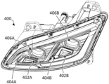
- FIG. 4 A illustrates a front view of an example headlamp assembly 400 .
- headlamp assembly comprises heating elements 402 A and 402 B, brackets 404 A and 404 B, and light sources 406 A and 406 B.
- Headlamp assembly 400 is provided as another example of a headlamp assembly comprising heating elements according to aspects described herein. Accordingly, it will be appreciated that headlamp assembly 400 comprises similar features as previously described headlamp assemblies and that such aspects are not necessarily re-described below in detail.
- bracket 404 A angles heating element 402 A so as to direct more of the associated radiation pattern (not pictured) toward the lens (not pictured) than if the base of heating element 402 A were positioned parallel to the bottom surface of the headlamp housing.
- Bracket 404 B may be similarly angled to retain heating element 402 B in a way that directs more of the associated radiation pattern (not pictured) toward the lens (not pictured).
- FIG. 4 B illustrates a perspective view of example heating elements 452 , 454 , 456 , and 458 having different geometries.
- the heating elements 452 - 458 are used in headlamp assembly 400 in FIG. 4 A .
- heating elements 458 and 456 may be positioned as elements 402 A and 402 B (e.g., as a driver-side headlamp assembly), while heating elements 452 and 454 may be used in a headlamp assembly that substantially mirrors headlamp assembly 400 on the opposite side of the vehicle.
- heating elements 452 - 458 are each comprised of emitter surfaces having angled surfaces.
- the surface of heating element 456 is comprised of angled surfaces 460 , 462 , and 464 , which affect the radiation pattern of heating element 456 .
- heating element 456 having angled surfaces 460 , 462 , and 464 may be used to increase the area/alter the shape of the radiation that heats the lens of headlamp assembly 400 , thereby adapting the region of the lens that is heated to match the beam pattern generated by light source 406 B.
- heating elements 452 - 458 are provided as examples and, in other examples, different geometries may be used based at least in part on the position of the heating element within the headlamp assembly and/or the beam pattern of one or more associated light sources.
Abstract
Description
Claims (18)
Priority Applications (2)
| Application Number | Priority Date | Filing Date | Title |
|---|---|---|---|
| US17/237,492 US11767957B2 (en) | 2020-04-30 | 2021-04-22 | Headlamp heater |
| CA3116667A CA3116667A1 (en) | 2020-04-30 | 2021-04-28 | Headlamp heater |
Applications Claiming Priority (2)
| Application Number | Priority Date | Filing Date | Title |
|---|---|---|---|
| US202063017846P | 2020-04-30 | 2020-04-30 | |
| US17/237,492 US11767957B2 (en) | 2020-04-30 | 2021-04-22 | Headlamp heater |
Publications (2)
| Publication Number | Publication Date |
|---|---|
| US20210341121A1 US20210341121A1 (en) | 2021-11-04 |
| US11767957B2 true US11767957B2 (en) | 2023-09-26 |
Family
ID=78293729
Family Applications (1)
| Application Number | Title | Priority Date | Filing Date |
|---|---|---|---|
| US17/237,492 Active US11767957B2 (en) | 2020-04-30 | 2021-04-22 | Headlamp heater |
Country Status (2)
| Country | Link |
|---|---|
| US (1) | US11767957B2 (en) |
| CA (1) | CA3116667A1 (en) |
Families Citing this family (2)
| Publication number | Priority date | Publication date | Assignee | Title |
|---|---|---|---|---|
| USD1017849S1 (en) | 2019-03-22 | 2024-03-12 | Canoo Technologies Inc. | Vehicle taillamp |
| USD1021167S1 (en) * | 2022-06-08 | 2024-04-02 | Changzhou T&D International Trading Co., Ltd. | Vehicle headlight |
Citations (19)
| Publication number | Priority date | Publication date | Assignee | Title |
|---|---|---|---|---|
| US20160215952A1 (en) * | 2011-02-09 | 2016-07-28 | Truck-Lite Co., Llc | Modular Headlamp Assembly with a Heating Element for Removing Water Based Contamination |
| US20160363286A1 (en) * | 2015-06-15 | 2016-12-15 | J.W. Speaker Corporation | Lens heating systems and methods for an led lighting system |
| US20170234503A1 (en) * | 2011-02-09 | 2017-08-17 | Truck-Lite Co., Llc | Headlamp Assembly with a Housing and Heat Sink Structure |
| US20180363878A1 (en) * | 2017-06-16 | 2018-12-20 | GM Global Technology Operations LLC | Lamp assembly with anisotropic heat spreader and vehicle having the same |
| CN109185826A (en) * | 2018-10-19 | 2019-01-11 | 广州鸿志汽车配件有限公司 | A kind of LED car lamp |
| US20190017676A1 (en) * | 2017-07-12 | 2019-01-17 | George A. Van Straten | Heat Source for Vehicle Illumination Assembly and Method |
| US20190017677A1 (en) * | 2017-07-12 | 2019-01-17 | Valeo North America, Inc. | Heater plate for vehicle light heating |
| US20190086054A1 (en) * | 2017-09-20 | 2019-03-21 | Mazda Motor Corporation | Front structure for vehicle and vehicle |
| US20190283658A1 (en) * | 2018-03-19 | 2019-09-19 | Koito Manufacturing Co., Ltd. | Vehicle lamp |
| US20200056756A1 (en) * | 2018-08-17 | 2020-02-20 | Creslite Inc | Freezing preventive led lamp |
| US20200072435A1 (en) * | 2016-11-17 | 2020-03-05 | Zkw Group Gmbh | Heat sink having variable thermal resistance |
| US20200247708A1 (en) * | 2017-10-10 | 2020-08-06 | Docter Optics Se | Method of producing an optical element from glass |
| US20200300440A1 (en) * | 2019-03-21 | 2020-09-24 | Panor Corp. | Systems and methods for led lens heating |
| US20200340660A1 (en) * | 2019-04-26 | 2020-10-29 | Van Straten Enterprises, Inc. | Heater and electromagnetic illuminator heater |
| US20210088197A1 (en) * | 2017-03-28 | 2021-03-25 | Aml Systems | Dehumidifier for a closed vehicle headlamp housing |
| US20210148539A1 (en) * | 2019-11-14 | 2021-05-20 | Min Hsiang Corporation | Vehicle Lamp with a Heating Function and Method for Manufacturing Components of the Vehicle Lamp |
| US11066047B1 (en) * | 2018-10-31 | 2021-07-20 | Keith Keller | LED tail light heater cover |
| US20210302006A1 (en) * | 2018-12-05 | 2021-09-30 | Yi Deng | Heating unit for light sources, installation and control system thereof |
| US20210339709A1 (en) | 2020-04-30 | 2021-11-04 | Paccar Inc | Headlamp heater control |
-
2021
- 2021-04-22 US US17/237,492 patent/US11767957B2/en active Active
- 2021-04-28 CA CA3116667A patent/CA3116667A1/en active Pending
Patent Citations (19)
| Publication number | Priority date | Publication date | Assignee | Title |
|---|---|---|---|---|
| US20170234503A1 (en) * | 2011-02-09 | 2017-08-17 | Truck-Lite Co., Llc | Headlamp Assembly with a Housing and Heat Sink Structure |
| US20160215952A1 (en) * | 2011-02-09 | 2016-07-28 | Truck-Lite Co., Llc | Modular Headlamp Assembly with a Heating Element for Removing Water Based Contamination |
| US20160363286A1 (en) * | 2015-06-15 | 2016-12-15 | J.W. Speaker Corporation | Lens heating systems and methods for an led lighting system |
| US20200072435A1 (en) * | 2016-11-17 | 2020-03-05 | Zkw Group Gmbh | Heat sink having variable thermal resistance |
| US20210088197A1 (en) * | 2017-03-28 | 2021-03-25 | Aml Systems | Dehumidifier for a closed vehicle headlamp housing |
| US20180363878A1 (en) * | 2017-06-16 | 2018-12-20 | GM Global Technology Operations LLC | Lamp assembly with anisotropic heat spreader and vehicle having the same |
| US20190017676A1 (en) * | 2017-07-12 | 2019-01-17 | George A. Van Straten | Heat Source for Vehicle Illumination Assembly and Method |
| US20190017677A1 (en) * | 2017-07-12 | 2019-01-17 | Valeo North America, Inc. | Heater plate for vehicle light heating |
| US20190086054A1 (en) * | 2017-09-20 | 2019-03-21 | Mazda Motor Corporation | Front structure for vehicle and vehicle |
| US20200247708A1 (en) * | 2017-10-10 | 2020-08-06 | Docter Optics Se | Method of producing an optical element from glass |
| US20190283658A1 (en) * | 2018-03-19 | 2019-09-19 | Koito Manufacturing Co., Ltd. | Vehicle lamp |
| US20200056756A1 (en) * | 2018-08-17 | 2020-02-20 | Creslite Inc | Freezing preventive led lamp |
| CN109185826A (en) * | 2018-10-19 | 2019-01-11 | 广州鸿志汽车配件有限公司 | A kind of LED car lamp |
| US11066047B1 (en) * | 2018-10-31 | 2021-07-20 | Keith Keller | LED tail light heater cover |
| US20210302006A1 (en) * | 2018-12-05 | 2021-09-30 | Yi Deng | Heating unit for light sources, installation and control system thereof |
| US20200300440A1 (en) * | 2019-03-21 | 2020-09-24 | Panor Corp. | Systems and methods for led lens heating |
| US20200340660A1 (en) * | 2019-04-26 | 2020-10-29 | Van Straten Enterprises, Inc. | Heater and electromagnetic illuminator heater |
| US20210148539A1 (en) * | 2019-11-14 | 2021-05-20 | Min Hsiang Corporation | Vehicle Lamp with a Heating Function and Method for Manufacturing Components of the Vehicle Lamp |
| US20210339709A1 (en) | 2020-04-30 | 2021-11-04 | Paccar Inc | Headlamp heater control |
Also Published As
| Publication number | Publication date |
|---|---|
| US20210341121A1 (en) | 2021-11-04 |
| CA3116667A1 (en) | 2021-10-30 |
Similar Documents
| Publication | Publication Date | Title |
|---|---|---|
| KR102410931B1 (en) | Retrofit lamp for automotive headlights | |
| JP4251941B2 (en) | head lamp | |
| US11767957B2 (en) | Headlamp heater | |
| EP1809074B1 (en) | Parts for vehicles and line heater unit for snow-melting structure part thereof | |
| CN217382788U (en) | Light emitting device and lighting system | |
| JP5150336B2 (en) | LED lamp | |
| US8905609B2 (en) | Lighting system with shutter, reflector, primary light engine and a secondary light engine coupled to shutter | |
| US20060007697A1 (en) | Front floodlight of a motor vehicle with adaptive light distribution | |
| US11199297B2 (en) | LED lamp | |
| US20170146211A1 (en) | Lighting device | |
| US10605427B1 (en) | Light source module and illumination device comprising the same | |
| JP2007305338A (en) | Vehicular lighting fixture | |
| US20150055944A1 (en) | Heated Lamp and Heated Bulb Assembly for Lamp | |
| KR101375465B1 (en) | Replaceable vehicle lamp with led light sources | |
| US11262029B2 (en) | Lighting device having semiconductor light source and at least one incandescent filament | |
| US20060227296A1 (en) | Light projector | |
| KR101453845B1 (en) | Safety LED lamp assembly for vehicle | |
| JP6272470B2 (en) | LED H4 retrofit lamp unit | |
| JP2008021602A (en) | Vehicular lighting fixture | |
| KR100785120B1 (en) | A vehocle's head lamp by using LED lamp | |
| JP6573562B2 (en) | Passing light source module and in-vehicle headlamp | |
| JP2019194948A (en) | Vehicle lamp fitting and driving assist device | |
| KR101416471B1 (en) | Lamp apparatus for an automobile | |
| US20080175013A1 (en) | Multiple Illumination Element Lamp Apparatus | |
| WO2020031880A1 (en) | Light source unit and lamp |
Legal Events
| Date | Code | Title | Description |
|---|---|---|---|
| AS | Assignment |
Owner name: PACCAR INC, WASHINGTON Free format text: ASSIGNMENT OF ASSIGNORS INTEREST;ASSIGNORS:CONWAY, SCOTT M.;HILSENBECK, THOMAS;KOPECKY, ROMAN;SIGNING DATES FROM 20210421 TO 20210422;REEL/FRAME:056011/0427 |
|
| FEPP | Fee payment procedure |
Free format text: ENTITY STATUS SET TO UNDISCOUNTED (ORIGINAL EVENT CODE: BIG.); ENTITY STATUS OF PATENT OWNER: LARGE ENTITY |
|
| STPP | Information on status: patent application and granting procedure in general |
Free format text: NON FINAL ACTION MAILED |
|
| STPP | Information on status: patent application and granting procedure in general |
Free format text: NON FINAL ACTION MAILED |
|
| STPP | Information on status: patent application and granting procedure in general |
Free format text: RESPONSE TO NON-FINAL OFFICE ACTION ENTERED AND FORWARDED TO EXAMINER |
|
| STPP | Information on status: patent application and granting procedure in general |
Free format text: FINAL REJECTION MAILED |
|
| STPP | Information on status: patent application and granting procedure in general |
Free format text: ADVISORY ACTION MAILED |
|
| STPP | Information on status: patent application and granting procedure in general |
Free format text: DOCKETED NEW CASE - READY FOR EXAMINATION |
|
| STPP | Information on status: patent application and granting procedure in general |
Free format text: NON FINAL ACTION MAILED |
|
| STPP | Information on status: patent application and granting procedure in general |
Free format text: NOTICE OF ALLOWANCE MAILED -- APPLICATION RECEIVED IN OFFICE OF PUBLICATIONS |
|
| STPP | Information on status: patent application and granting procedure in general |
Free format text: PUBLICATIONS -- ISSUE FEE PAYMENT RECEIVED |
|
| STPP | Information on status: patent application and granting procedure in general |
Free format text: PUBLICATIONS -- ISSUE FEE PAYMENT VERIFIED |
|
| STCF | Information on status: patent grant |
Free format text: PATENTED CASE |