US1175813A - Controlling means for internal-combustion engines. - Google Patents
Controlling means for internal-combustion engines. Download PDFInfo
- Publication number
- US1175813A US1175813A US1907372728A US1175813A US 1175813 A US1175813 A US 1175813A US 1907372728 A US1907372728 A US 1907372728A US 1175813 A US1175813 A US 1175813A
- Authority
- US
- United States
- Prior art keywords
- valve
- spring
- engine
- rod
- air
- Prior art date
- Legal status (The legal status is an assumption and is not a legal conclusion. Google has not performed a legal analysis and makes no representation as to the accuracy of the status listed.)
- Expired - Lifetime
Links
- 238000002485 combustion reaction Methods 0.000 title description 10
- 239000000446 fuel Substances 0.000 description 16
- 230000001276 controlling effect Effects 0.000 description 11
- 230000001105 regulatory effect Effects 0.000 description 10
- 230000006835 compression Effects 0.000 description 9
- 238000007906 compression Methods 0.000 description 9
- 230000009471 action Effects 0.000 description 7
- 238000010276 construction Methods 0.000 description 6
- 239000000203 mixture Substances 0.000 description 5
- 238000010790 dilution Methods 0.000 description 3
- 239000012895 dilution Substances 0.000 description 3
- 230000003292 diminished effect Effects 0.000 description 3
- 230000003467 diminishing effect Effects 0.000 description 2
- 230000007246 mechanism Effects 0.000 description 2
- 241000239290 Araneae Species 0.000 description 1
- 241001550206 Colla Species 0.000 description 1
- 230000001133 acceleration Effects 0.000 description 1
- 230000008901 benefit Effects 0.000 description 1
- 230000036461 convulsion Effects 0.000 description 1
- 230000007423 decrease Effects 0.000 description 1
- 230000001419 dependent effect Effects 0.000 description 1
- 230000000694 effects Effects 0.000 description 1
- 230000006872 improvement Effects 0.000 description 1
- 239000007788 liquid Substances 0.000 description 1
- 230000004044 response Effects 0.000 description 1
- 230000004043 responsiveness Effects 0.000 description 1
- 230000000284 resting effect Effects 0.000 description 1
- 230000000979 retarding effect Effects 0.000 description 1
- 238000000926 separation method Methods 0.000 description 1
- 210000001364 upper extremity Anatomy 0.000 description 1
Images
Classifications
-
- F—MECHANICAL ENGINEERING; LIGHTING; HEATING; WEAPONS; BLASTING
- F16—ENGINEERING ELEMENTS AND UNITS; GENERAL MEASURES FOR PRODUCING AND MAINTAINING EFFECTIVE FUNCTIONING OF MACHINES OR INSTALLATIONS; THERMAL INSULATION IN GENERAL
- F16K—VALVES; TAPS; COCKS; ACTUATING-FLOATS; DEVICES FOR VENTING OR AERATING
- F16K11/00—Multiple-way valves, e.g. mixing valves; Pipe fittings incorporating such valves
- F16K11/10—Multiple-way valves, e.g. mixing valves; Pipe fittings incorporating such valves with two or more closure members not moving as a unit
- F16K11/14—Multiple-way valves, e.g. mixing valves; Pipe fittings incorporating such valves with two or more closure members not moving as a unit operated by one actuating member, e.g. a handle
- F16K11/16—Multiple-way valves, e.g. mixing valves; Pipe fittings incorporating such valves with two or more closure members not moving as a unit operated by one actuating member, e.g. a handle which only slides, or only turns, or only swings in one plane
-
- Y—GENERAL TAGGING OF NEW TECHNOLOGICAL DEVELOPMENTS; GENERAL TAGGING OF CROSS-SECTIONAL TECHNOLOGIES SPANNING OVER SEVERAL SECTIONS OF THE IPC; TECHNICAL SUBJECTS COVERED BY FORMER USPC CROSS-REFERENCE ART COLLECTIONS [XRACs] AND DIGESTS
- Y10—TECHNICAL SUBJECTS COVERED BY FORMER USPC
- Y10T—TECHNICAL SUBJECTS COVERED BY FORMER US CLASSIFICATION
- Y10T137/00—Fluid handling
- Y10T137/8593—Systems
- Y10T137/87571—Multiple inlet with single outlet
- Y10T137/87676—With flow control
Definitions
- My invention relates to simple and effecfor controlling engines of the internal ⁇ combustion type and more particularly to the provision of a novel form or type of automatic air valve for regulating the auxiliary air supply of the engine.
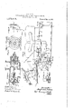
- Figure 1 shows a system of control embodying one form of my invention and as applied to a partial assemblage of parts upon a motor vehicle;
- Fig. 2 is a vertical sectional detail of a mixing chamber provided with my automatic air valve;
- Fig. 3 is an elevation of the left or rear head of the mixing chamber, showing' the port openings of the' auxiliary' air supply;
- Fig. 4f a detail in plan conventionally representing a speed governor attached to the governor rods shown in Figil, and Fig. 5, is a detail showing the connection of the accelerating lever to the actuating rod.
- l provide a suitable mixing chamber, l, Fig. 2, which is mounted upon 'the carburetor 2, Fig. 1, which may be of any suitable or desired construction, but which as here shown is adapted for use with an engine of thc multiple cylinder' type employed upon motor vehicles.
- This engine, its carburcter and mifxing chamber are all .provided with suitable devices for controlling the same which will be fully understood and appreciated by thoseskillcd in the art.
- the engine is supplied with a mixture of gaseous fuel through the admission pipe 3, Fig. 2, leading from the mixing chamber, l, which is preferably mounted within the casing and directly over the earbureter 2.
- the carbureter is adapted to receive a supply of liquid fuel from a suitable source(not'shown), atomizing or otherwise gasifying the same, and delivering to the mixing chamber 1, through the opening ⁇ 4 in the under side thereof, a supply of the gasilied fuel combined with a suitable quantity of air.
- Exit or discharge from the mixing chamber l takes place through the port 5, pref- 'erably at the right or front end of the former, i'nto the annular chamber G, which .directly communicates with the admission pipe 3 leading to the engine, rlhc port 5, is controlled by a piston Valve 7 Fig. 2, mounted to slide longitudinally or lengthwise of said chamber and acting to open or close'the port or 'vary the amount of port opening.
- rlbis valvev is actuated by. means of an actuating rod S, which passes through the head of the mixing chamber and at its opposite end is connected with a speed gov,- ernor as shown in l.
- the governor operates to throw the'vala'e rod, 8, aud the valve, 7, connected therewith, to partially or wholly close the port. 5, according to the speed of the engine.
- llxtending through the opposite or rear head ll of the mixing chamber is an auxiliary valve controlling rod, S), thc'inner end of which is adapted to enter and slide in an axial opening in the valve body and abut the opposite end of the actuating rod 8 and thereby to vary the closing movement of the alve 7.
- S auxiliary valve controlling rod
- valve regulating rod 9 is connected to a foot controlled acceleratingl lever 10 by which the rod may be slid inward not only to vary but to limit the port closing move-v ment of the valve i' and thereby to maintain a, desired supply of'iuel and independent or irrespective of the, action of said governor.
- the governor may be operated through the speed of the Tengine, to throw the valve rod 8, inwardly, to push the Valve to the position indicated in dotted lines in Fig. 2 with the end of said rod S in engagement by the valve .regulating rod 9, which has been set by ysaid foot 1cver10 to prevent further inward movement, thus maintaining a fixed port opening, ⁇ between the inner edge of the valve and said port.
- the rear head 11 oi' the latter Figs. 2 and f3 is provided with an air port having a plurality ot' openings 12, which normally admit air freely to said chamber.
- the quantity of air, however, which is admitted through these openings may be varied through the provision of an exterior throttling disk 13, which is provided with openings or apertures which normally coincide or are alined ⁇ with those of said head 11.
- This disk is rotatably mounted on the tubular bearing' 14 in which the rod 9 slides and its periphery is 'provided with concentric slots 15, which receive adjusting bolts or screws 1G, secured in said head.
- the screws receive clamping nuts 16, adapted to be turned to clamp the plate in position.
- This construction permits said disk to be rotated or turned and secured in desired position correspondingly to increase or diminish and maintain a desired amount of port opening in said head.
- the bearing 14 is strengthened by means of spider arms 17 connecting" the same with the inner face of the disk ot said head 11.
- this valve consists of a spiral coil spring 18 preferably coiled into the form of a truncated cone with its base secured to said head 11 adjacent the threaded eonnection of the latter with the mixing chamber 1.
- This spring.,r is removably held in place
- the inner coil of this coil spring closely embraces the bearing 14 and the intermediate coils or convolutions normally lie close together, or rest in engagement with one another,so that they normally cover the port 12 and prevent the admission. of air,
- the head 11 is removably secured to the mixing chamber to permit it to be readily removed so that the valve 18 may be removed or secured or one of different strength substituted.
- valves of this type it is highly desirable that the force or the means acting ⁇ in opposition to the suction of the valve and tending to re-y store it to and maintain it in its normal or closed position should be of an extremely delicate and sensitive nature, otherwise the valve tends to open too late or not at all, or, when once opened to remain so, or to overthrow beyond the required position. This fault characterizes to a greater or less degree all valves of this typewith which I am familiar and which the present construction avoids.
- the valve itself constitutes the means for restoring it to its normal closed position and is of the desired delicacy both in construction and in operation, yieldingreadily upon variation in the internal pressure to admit the desired admixture of fresh air and closing instantaneously when the speed of the machine decreases to such usual running conditions that no auxiliary air supply is required.
- I thus provide an automatic valve'structurally providing' its own means to permit free opening and closing' movement and without the aid of auxiliary springs or other devices to return the valve toits seat.
- This movement reeiprocates the connected valve rod S and its valve 7 ⁇ to move the latter in one or the other directions relative to and upon its seat in the front end of the mixing' chamber and thereby to increase or to diminish the extent of 130 invasie opening of the port 5 and hence the amount of fuel mixture supplied to the engine.
- valve regulating rod 9 which by its action aries the closing movement of the valve 7 is adapted to be operated by suitable mechanism arranged in position to be readily controlled by the operator.
- said rod has a sliding lit inthe head 1l ot the mixing chamber and exteriorly to the latter is provided with a collar 26 between which and an adjacent colla; ⁇ 27, loosely mounted on said rod, is a compression spring 28.
- This spring normally opposes backward movement ot' said rod 9. After thc engine has been Started and the valve 7 has been moved to the dotted line position showing Fig. 2, this spring may be made to oppose and regulate 'the governor movement to an extent dependent upon its compression.
- the collar 27 is secured to a link 29 ⁇ iointed to a horizontal arm 30, the latter belng fixedly secured to the upper end of a short shath journaled in a bracket 32 and provided at its lower end with a bevel gear This gear meshes with a similar gear upon the lower end ot' an inclined shaft 35 which passes through the controlling post l and receives at its upper extremity an operating handle 36.
- 'lhis latter may be oseillated to the right or lel't to rotate the shat't 35 and its gears 3%-, and 33, to swing the link 30 and to move the collar 27 toward and from the head ll, ot the mixing chamber.
- any suitable means may be provided tor holding the lever 3G in adjusted position. herein partially shown at Ill' as a segmental rack upon the end ot' the controlling post and adapted to be engaged by spi-iin?,- pressed 'tooth or upon the end ot said lever 3G.
- the controlling post is provided with the usual steering wheel, which during the operation of the vehicle is held by the operator, so that the hand lever 36 is imme- T his sleeve carries at its head an actuating l lever 42 which shifts the camshaft (not shown) for varying the action of the ignition cams and advancing or retarding the time of ignition.
- a cap'i which is adapted to be slid back and forth by a yoke shaped vertical arm A of the supporting lever l0, this lever being fulcrumed at 45 and having its rear arm inclined downwardly in position to be conveniently actuated by an accelerating pin 46.
- the head oit this pin extends up through the ioor of the carriage where it is presented for convenient actuation by the oot'ot the operator.
- depression ot this pin depresses the long arfn ot the lever 10 causing its vertical arm to be thrown forward and sliding the accelerating rod also forward in position to limit the inward throw of the throttle valve T, so that a desired port opening may be maintained or to positively slide the valve forward against the action ot' the governor for ltemporarily increasing the amount ot port opening. and thereby to increase the tuel supply and hence the engine speed.
- the arm Llei ot the accelerating lever l0 is normallyf retracted by a spring 47 connecting said arm with a stationary part ot the frame and normally operating to bring the cap 43v against an abutment it?
- auxiliary air supply valve 18 is regulated and c011- ytrolled by the position and movement of the throttle valve-7, so that the amount of auxiliary air supply to be mixed with theinixed fuel will vary with the speed of the engine or with the speed acceleration produced by varying the amount of port opening at 5.
- the proper adjustment of the governor provides means for maintain ing any usual or desired engine speed, which may be increased either for the instant or for any length of time by increasing the compression of .the spring Q8 through suitable adjustment oi ⁇ the operating lever 36.
- the governor slides the throttle valve 7 inwardly, the rod 8 also slides inwardly simultaneously and pushes the Vabutting rod 9 back against the adjusted compression of the spring 28.
- auxiliary rod 9 may be adjusted in or out and so that its spring adjusted throttle will be more or less under the controlof the governor or under that of the foot controlled actuator, though, as ordinarily adjusted, it is placed in an inf termediate position to limit the action of the governor and maintain a desired speed.
- my invention'l have provided a valve that in both its op'iiing and closing movements responds with extreme sensitiveness and delicacy t@ thjc movements-of the engine piston and throttle 7 and that, fur ther-more, opera tes lwithout any sudden jerk as would occur were it rigid or positively seated against stops, abutments, valve seats or the like.
- My valve provides its own cushioning means and closes-automatically When'the suction is not sufficient .to main.-d tain it opened.
- valve In practical use, the above type of valve produces marked improvement in the oporation of the engine, being practically noise-v less, and eliminating the vibration or hammerng which has hitherto characterized the valves usually employed :for th purpose,
- the valve is of especial advantage, however, in respect to the delicacy with/Which it automatically operates in response to the speed requirements of the engine for admitting varying quantitiesvof air for the proper dilution of the fuel mixture.
- a mixing chamber having a head provided with a plurality of port open ings
- a throttle plate movably mounted upon said head having openings normally coinciding or alined with those in said headv and adapted to be adjusted for moving said openings into or out of coinciding position for varying the admission opening to said chami ber
- a coil spring valve secured to the inner face of said head and covering the port openings therein and normally maintained with its coils in contact one with another to prevent the admission of air through said openings but adapted to be drawn inward to separate said coils to admit air.
- an air valve comprising a spiral coil spring, a main intake port, an auxiliary intake port leading invvardly toward and controlled by said valve, and throttle means for said auxiliary intake port.
- an air valve comprising a spiral coil spring, seating means for thesuccessive convolutions of said valve, and throttle means for said auxiliary air intake.
- an air valve comprising a spiral coiled spring having a general cone-shaped form, a seat for the base of the spring, a central bearing stem about which the opposite end of the spring is coiled and with relation to which it is free to move axially, and means for securing said base to said seat to secure said spring against axial movement bodily While permitting freedom of movement throughout the remainder of said spring.
- an air valve comprising a spiral coiled spring, a main intake port, an auxiliary intake port leading inwardly toward and controlled by saidvalve, and throttle means for said main intake ort.
- a fuel and air supply device for internal combustion engines having a main and an auxiliary air intake, and an air valve for said auxiliary intake comprising a spiral coil spring and seating means for the suc. cessive convolutions of said spring.
- a fuel and air supply device for internal combustion engines having a main and auxiliary air intake and an air valve for said auxiliary intake comprising a conical coil spring and seating means for the successive convolutions of said spring to engage the same along elements of the cone.
Landscapes
- Engineering & Computer Science (AREA)
- General Engineering & Computer Science (AREA)
- Mechanical Engineering (AREA)
- Control Of Throttle Valves Provided In The Intake System Or In The Exhaust System (AREA)
Description
A. L. RIKER. CONTROLLING MEANS FOR INTERNAL COMBUSTION ENGINES.
' APPLICATION FILED MAY 9I9'7, Ll'.
Patented Mar. 14, 191e.
FINN
State of Connecticut, have invented an lm- .tive means entre@ errar-,ns inac- A'JSI'IIIEWVv L. BIKER, OF BRIDGEPORT, CONNllGT1CU". ,v ASSIGNOR T THE LOCOMOBILE COMPANY F AMERICA, OF NEW YORK, N,
Y A CORBORATION OF WEST VIRGINIA.
CONTROLLING MEANS FOR INTERNALACO'MBUS'LIION ENGINES.
Specification of Letters Patent.
Application filed May 9, 1907. Serial No. 372,728.
To all whom t may concern Be it known that I, ANDREW L. BIKER, a citizen of the United yStates residing at Bridgeport, in the county of Fairfield and provement in Controlling Means for Internal-Combustion Engines, of which the following description, in connection with the accompanying drawings, is a speciiication, likeletters on the drawings representing like parts.
My invention relates to simple and effecfor controlling engines of the internal `combustion type and more particularly to the provision of a novel form or type of automatic air valve for regulating the auxiliary air supply of the engine.
My invention, however, will be best understood and appreciated by reference to the following description, when taken in connection with the accompanying drawings, of onespecic embodiment thereof, selected for purposes of illustration,-its scope being more particularly pointed out in the appended claims. nlthe drawings; Figure 1, shows a system of control embodying one form of my invention and as applied to a partial assemblage of parts upon a motor vehicle; Fig. 2, isa vertical sectional detail of a mixing chamber provided with my automatic air valve; Fig. 3, is an elevation of the left or rear head of the mixing chamber, showing' the port openings of the' auxiliary' air supply; Fig. 4f, a detail in plan conventionally representing a speed governor attached to the governor rods shown in Figil, and Fig. 5, is a detail showing the connection of the accelerating lever to the actuating rod.
Referring to the drawings and to the particular embodiment of my invention herein selected for purposes of illustration, l provide a suitable mixing chamber, l, Fig. 2, which is mounted upon 'the carburetor 2, Fig. 1, which may be of any suitable or desired construction, but which as here shown is adapted for use with an engine of thc multiple cylinder' type employed upon motor vehicles. This engine, its carburcter and mifxing chamber are all .provided with suitable devices for controlling the same which will be fully understood and appreciated by thoseskillcd in the art.
While my invention,
as here shown, is' especially adapted to the use upon engines of motor vehicles and is described with reference thereto, it will be understood that in many of its broad features it is equally applicable to engines employed for other purposes than .the propulsion of motor vehicles.
In the disclosed embodiment of myinvention here shown, the engine is supplied with a mixture of gaseous fuel through the admission pipe 3, Fig. 2, leading from the mixing chamber, l, which is preferably mounted within the casing and directly over the earbureter 2. The carbureter is adapted to receive a supply of liquid fuel from a suitable source(not'shown), atomizing or otherwise gasifying the same, and delivering to the mixing chamber 1, through the opening` 4 in the under side thereof, a supply of the gasilied fuel combined with a suitable quantity of air. u
Exit or discharge from the mixing chamber l takes place through the port 5, pref- 'erably at the right or front end of the former, i'nto the annular chamber G, which .directly communicates with the admission pipe 3 leading to the engine, rlhc port 5, is controlled by a piston Valve 7 Fig. 2, mounted to slide longitudinally or lengthwise of said chamber and acting to open or close'the port or 'vary the amount of port opening. rlbis valvev is actuated by. means of an actuating rod S, which passes through the head of the mixing chamber and at its opposite end is connected with a speed gov,- ernor as shown in l. `When the engine is started, the governor operates to throw the'vala'e rod, 8, aud the valve, 7, connected therewith, to partially or wholly close the port. 5, according to the speed of the engine. llxtending through the opposite or rear head ll of the mixing chamber, is an auxiliary valve controlling rod, S), thc'inner end of which is adapted to enter and slide in an axial opening in the valve body and abut the opposite end of the actuating rod 8 and thereby to vary the closing movement of the alve 7. The opiiosite exterior an rear end of said. valve regulating rod 9 is connected to a foot controlled acceleratingl lever 10 by which the rod may be slid inward not only to vary but to limit the port closing move-v ment of the valve i' and thereby to maintain a, desired supply of'iuel and independent or irrespective of the, action of said governor. For example, the governor may be operated through the speed of the Tengine, to throw the valve rod 8, inwardly, to push the Valve to the position indicated in dotted lines in Fig. 2 with the end of said rod S in engagement by the valve .regulating rod 9, which has been set by ysaid foot 1cver10 to prevent further inward movement, thus maintaining a fixed port opening,` between the inner edge of the valve and said port. By this arrangement, means are provided for maintaining a desired supply of fuel and which may be increased or diminished by operating the accelerating lever 10.
For the further air dilution of the fuel mixture which enters the mixing chamber 1, the rear head 11 oi' the latter Figs. 2 and f3, is provided with an air port having a plurality ot' openings 12, which normally admit air freely to said chamber. The quantity of air, however, which is admitted through these openings may be varied through the provision of an exterior throttling disk 13, which is provided with openings or apertures which normally coincide or are alined `with those of said head 11. This disk is rotatably mounted on the tubular bearing' 14 in which the rod 9 slides and its periphery is 'provided with concentric slots 15, which receive adjusting bolts or screws 1G, secured in said head. The screws receive clamping nuts 16, adapted to be turned to clamp the plate in position. This construction permits said disk to be rotated or turned and secured in desired position correspondingly to increase or diminish and maintain a desired amount of port opening in said head. Interiorly the bearing 14 is strengthened by means of spider arms 17 connecting" the same with the inner face of the disk ot said head 11.
An important ieature of my invention resides in the novel form o'f'valve provided for normally closing; the openings in the ports in the head 11 through which the auxiliary air supply is admitted. As here shown, this valve consists of a spiral coil spring 18 preferably coiled into the form of a truncated cone with its base secured to said head 11 adjacent the threaded eonnection of the latter with the mixing chamber 1. This spring.,r is removably held in place| by a retainingr ring 19, which engages the outer coils of the spring, and is secured to the inner surface of the mixing chamber. The inner coil of this coil spring closely embraces the bearing 14 and the intermediate coils or convolutions normally lie close together, or rest in engagement with one another,so that they normally cover the port 12 and prevent the admission. of air,
The head 11 is removably secured to the mixing chamber to permit it to be readily removed so that the valve 18 may be removed or secured or one of different strength substituted.
During the running of the engine, the
'suction produced in the air chamber varies with the increase in engine speed. Upon such increase, the spring 18 is drawn in-- wardly and its convolutions separate one from another, to permit to pass between them the air which has already passed through the more or less throttled openings 12 in air port. This spring` will remain in a more or less extended inner position while the suction is suicient to overcome its tension during' which air is admitted for the further dilution of the fuel mixture. 1t is obvious that the inward motion of the spring and the amount of separation between the coils and hence the extent of valve opening is automatically regulated by the amount of suction and hence by the speed.A In valves of this type, it is highly desirable that the force or the means acting` in opposition to the suction of the valve and tending to re-y store it to and maintain it in its normal or closed position should be of an extremely delicate and sensitive nature, otherwise the valve tends to open too late or not at all, or, when once opened to remain so, or to overthrow beyond the required position. This fault characterizes to a greater or less degree all valves of this typewith which I am familiar and which the present construction avoids. In the present embodiment or' my invention, the valve itself constitutes the means for restoring it to its normal closed position and is of the desired delicacy both in construction and in operation, yieldingreadily upon variation in the internal pressure to admit the desired admixture of fresh air and closing instantaneously when the speed of the machine decreases to such usual running conditions that no auxiliary air supply is required. I thus provide an automatic valve'structurally providing' its own means to permit free opening and closing' movement and without the aid of auxiliary springs or other devices to return the valve toits seat.
F or connecting' the outer or iront end ot the valve rod 8 with the governor, it is secured by an adjustable turn buckle represented at 20, Fig. 1, to a rod 21, the front Jforked end of which is in turn ljointed at Y2i?, Figs. 1 and 4t, to the outer end ot' a laterally extending lever Q3. This lever is fulcrumcd at 21 upon the engine casing andhas interim` connections with a governor of the centrifugal type. conventionally represented at Q5, Fig'. 4. This governor is driven 'through suitable gearing' from the engine shaft, so that with the changes in the speed of the'eng'ine, the lever 23 is oseillated on its iulcrum Q4. This movement reeiprocates the connected valve rod S and its valve 7` to move the latter in one or the other directions relative to and upon its seat in the front end of the mixing' chamber and thereby to increase or to diminish the extent of 130 invasie opening of the port 5 and hence the amount of fuel mixture supplied to the engine.
When the engine is at rest the governor draws the piston valve to the full line position shown in Fig. 2, but as soon as; the engine reaches normal speed, the governor throws said valve approximately to the po` sition represented in dotted lines from which position it varies to one side or the other according to the engine speed. n
lt will be obvious 'to those skilledvin the art, that the movement of the piston valve eauses a responsive action ot the coill spring valve 1S thus to regulate the auxiliary air supply according to the speed ot the engine, inereasing said supply with an *increase in engine speed and diminishing the same as the speed is diminished.
T he valve regulating rod 9, which by its action aries the closing movement of the valve 7 is adapted to be operated by suitable mechanism arranged in position to be readily controlled by the operator.
llet'erring to the drawings.'particularly Fig. 2. said rod has a sliding lit inthe head 1l ot the mixing chamber and exteriorly to the latter is provided with a collar 26 between which and an adjacent colla;` 27, loosely mounted on said rod, is a compression spring 28. This spring normally opposes backward movement ot' said rod 9. After thc engine has been Started and the valve 7 has been moved to the dotted line position showing Fig. 2, this spring may be made to oppose and regulate 'the governor movement to an extent dependent upon its compression. That this adjustment may be readily made by the operator, the collar 27 is secured to a link 29 `iointed to a horizontal arm 30, the latter belng fixedly secured to the upper end of a short shath journaled in a bracket 32 and provided at its lower end with a bevel gear This gear meshes with a similar gear upon the lower end ot' an inclined shaft 35 which passes through the controlling post l and receives at its upper extremity an operating handle 36. 'lhis latter may be oseillated to the right or lel't to rotate the shat't 35 and its gears 3%-, and 33, to swing the link 30 and to move the collar 27 toward and from the head ll, ot the mixing chamber. '.lhismovement inereases or diminishes the compression ot the spring 2S and the yielding torce opposed to the movement ot the rod S as the governor moves the latter inward against the spring controlled regulating "rod 9. Any suitable means may be provided tor holding the lever 3G in adjusted position. herein partially shown at Ill' as a segmental rack upon the end ot' the controlling post and adapted to be engaged by spi-iin?,- pressed 'tooth or upon the end ot said lever 3G.
and 9 to abut in all positions of the valve. Fnrthermore, by increasing or diminishing the tension or compression of said spring, a higher or lower engine speed respectively` will be required to operate the valve, the latter obviously ciosing more or less rapidly under the varying tensions otasaid spring. As stated, the controlling post is provided with the usual steering wheel, which during the operation of the vehicle is held by the operator, so that the hand lever 36 is imme- T his sleeve carries at its head an actuating l lever 42 which shifts the camshaft (not shown) for varying the action of the ignition cams and advancing or retarding the time of ignition.
For connecting the accelerating rod 9 with the foot actuating lever 10, the following mechanism is provided. Slidably secured at the rear end of the rod 9 is a cap'i which is adapted to be slid back and forth by a yoke shaped vertical arm A of the supporting lever l0, this lever being fulcrumed at 45 and having its rear arm inclined downwardly in position to be conveniently actuated by an accelerating pin 46. The head oit this pin extends up through the ioor of the carriage where it is presented for convenient actuation by the oot'ot the operator. Depression ot this pin depresses the long arfn ot the lever 10 causing its vertical arm to be thrown forward and sliding the accelerating rod also forward in position to limit the inward throw of the throttle valve T, so that a desired port opening may be maintained or to positively slide the valve forward against the action ot' the governor for ltemporarily increasing the amount ot port opening. and thereby to increase the tuel supply and hence the engine speed. The arm Llei ot the accelerating lever l0 is normallyf retracted by a spring 47 connecting said arm with a stationary part ot the frame and normally operating to bring the cap 43v against an abutment it? on the controlling post` there being provided in this position ot the cap a considerable clearance between the inner wall oi the same and the end ot the actuating rod, so that the latter is tree to bd moved in one or the other direction, withoutfintertering with the cap, as the throttle valve responds to the control ot the governor.
From the foregoing description it will be readily understood by those skilled in the art, that the responsiveness of the auxiliary air supply valve 18 is regulated and c011- ytrolled by the position and movement of the throttle valve-7, so that the amount of auxiliary air supply to be mixed with theinixed fuel will vary with the speed of the engine or with the speed acceleration produced by varying the amount of port opening at 5.
In operation, the proper adjustment of the governor provides means for maintain ing any usual or desired engine speed, which may be increased either for the instant or for any length of time by increasing the compression of .the spring Q8 through suitable adjustment oi` the operating lever 36. As the governor slides the throttle valve 7 inwardly, the rod 8 also slides inwardly simultaneously and pushes the Vabutting rod 9 back against the adjusted compression of the spring 28. By this arrangement, the inward movement of said rods and hence throttle oi the said valve is always against and to effect compression of the spring 28,
so that the speed or closing movement of said valve may be increased or diminished by adjusting the compression of said spring.
In any adjusted position of the throttle, the suction produced by the operation of the engine will cause the valve 18 to yield inwardly to permit an admixture of "L `sh air, the amount of opening of said valve and hence the auxiliary air supply depending upon the speed of the engine which as has been stated, is regulated by the amount of throttling. Obviously the auxiliary rod 9 may be adjusted in or out and so that its spring adjusted throttle will be more or less under the controlof the governor or under that of the foot controlled actuator, though, as ordinarily adjusted, it is placed in an inf termediate position to limit the action of the governor and maintain a desired speed.
By providing the rod 9 with a compression spring 28, which may be adjusted to limit the inward movement of the rod 9 and thereby to limit the inward movement of the valve, means are provided for preventing the governor from causing an overthrow of said valve in speeding up upon starting the machine, and preventing a diminution in the amount of mixed fuel and the auxiliary air suj'iiily needed for the most effective working of the engine.
Byl my invention'l have provided a valve that in both its op'iiing and closing movements responds with extreme sensitiveness and delicacy t@ thjc movements-of the engine piston and throttle 7 and that, fur ther-more, opera tes lwithout any sudden jerk as would occur were it rigid or positively seated against stops, abutments, valve seats or the like. My valve provides its own cushioning means and closes-automatically When'the suction is not sufficient .to main.-d tain it opened. j
In practical use, the above type of valve produces marked improvement in the oporation of the engine, being practically noise-v less, and eliminating the vibration or hammerng which has hitherto characterized the valves usually employed :for th purpose, The valve is of especial advantage, however, in respect to the delicacy with/Which it automatically operates in response to the speed requirements of the engine for admitting varying quantitiesvof air for the proper dilution of the fuel mixture.
By providing the head of the mixingA chamber with adjustable port openings and mounting the valve upon its inner face, in the manner described, a very simple construction is provided, enabling the casing to be made at a much less cost than where' auxiliary air chambers, valve seats, valves, and spring controlling means therefor are employed.'
While I have shown and described my in.n vention' with reference to a single preferred embodiment, it will be'understood that the same is not limited thereto, nor to the spe.- cific details of construction and arrangement herein set forth for purposes of illustration and description only, the same being capable o fmodiication within wide limits without departing from the spirit and scope thereof.
I claim:
l. In an internal combustion engine, the
combination of a mixing chamber having a head provided with a plurality of port open ings, a throttle plate movably mounted upon said head having openings normally coinciding or alined with those in said headv and adapted to be adjusted for moving said openings into or out of coinciding position for varying the admission opening to said chami ber, and a coil spring valve secured to the inner face of said head and covering the port openings therein and normally maintained with its coils in contact one with another to prevent the admission of air through said openings but adapted to be drawn inward to separate said coils to admit air.
2. In an internal coiribustion engine, the combination of an air mixing chamber, a throttle for regulating the amount of Jfuel supply to the engine, means for normally controlling said throttle, a device comprising a rod slidable through the wall of said air mixing chamber and adapted to engage 'said throttle for regulating the action thereof, air supply means comprising port means in the wall of the ai i' chamber through which said rod slides and concentric therewith and a conical spiral coil .spring seated by its base upon said wall and surrounding said. port means and said rod and constituting a closure therefor. j
3. In an internal combustion engine, the
ilo
combination of an air chamber having a head provided with an interiorly projecting central bearing and one or more openings for the admission of air to Said chamber, and a conical coil spring 18 secured by its base upon the inner face of said head 11 and having its"lspirals in normal contact one with another, and With its inner spiral end normally resting upon said bearinfr.
4. In a fuel and air supply device for internal combustion engines', an air valve comprising a spiral coil spring, a main intake port, an auxiliary intake port leading invvardly toward and controlled by said valve, and throttle means for said auxiliary intake port. 1
5. In a fuel and air supply device for internal combustion engines having a main and an auxiliary air intake, an air valve comprising a spiral coil spring, seating means for thesuccessive convolutions of said valve, and throttle means for said auxiliary air intake.
6. In a fuel and air supply device for internal combustion engines, an air valve comprising a spiral coiled spring having a general cone-shaped form, a seat for the base of the spring, a central bearing stem about which the opposite end of the spring is coiled and with relation to which it is free to move axially, and means for securing said base to said seat to secure said spring against axial movement bodily While permitting freedom of movement throughout the remainder of said spring.
7. In a fuel and air supply device for nternal combustion engines, an air valve comprising a spiral coiled spring, a main intake port, an auxiliary intake port leading inwardly toward and controlled by saidvalve, and throttle means for said main intake ort. p 8. A fuel and air supply device for internal combustion engines having a main and an auxiliary air intake, and an air valve for said auxiliary intake comprising a spiral coil spring and seating means for the suc. cessive convolutions of said spring.
9. A fuel and air supply device for internal combustion engines having a main and auxiliary air intake and an air valve for said auxiliary intake comprising a conical coil spring and seating means for the successive convolutions of said spring to engage the same along elements of the cone.
In testimony whereof, I have signed my name to this specification, in the presence of two subscribing Witnesses.
ANDREV L. RIKER.
Vitnesses:
R. M. YOUNG, J. A.. KINGMAN.
Priority Applications (1)
| Application Number | Priority Date | Filing Date | Title |
|---|---|---|---|
| US1907372728 US1175813A (en) | 1907-05-09 | 1907-05-09 | Controlling means for internal-combustion engines. |
Applications Claiming Priority (1)
| Application Number | Priority Date | Filing Date | Title |
|---|---|---|---|
| US1907372728 US1175813A (en) | 1907-05-09 | 1907-05-09 | Controlling means for internal-combustion engines. |
Publications (1)
| Publication Number | Publication Date |
|---|---|
| US1175813A true US1175813A (en) | 1916-03-14 |
Family
ID=3243805
Family Applications (1)
| Application Number | Title | Priority Date | Filing Date |
|---|---|---|---|
| US1907372728 Expired - Lifetime US1175813A (en) | 1907-05-09 | 1907-05-09 | Controlling means for internal-combustion engines. |
Country Status (1)
| Country | Link |
|---|---|
| US (1) | US1175813A (en) |
-
1907
- 1907-05-09 US US1907372728 patent/US1175813A/en not_active Expired - Lifetime
Similar Documents
| Publication | Publication Date | Title |
|---|---|---|
| US1191700A (en) | Auxiliary air-valve. | |
| US2090246A (en) | Throttle control device for automobiles | |
| US1175813A (en) | Controlling means for internal-combustion engines. | |
| US2361103A (en) | Throttle valve control mechanism for internal-combustion engines | |
| US3171868A (en) | Automatic choke for carburetor | |
| US2316618A (en) | Internal combustion engine | |
| US1598243A (en) | Auxiliary air and fume supply for explosive engines | |
| US2935076A (en) | Engine governor control valve | |
| US2990821A (en) | Secondary throttle dampening device | |
| US1104119A (en) | Governor for internal-combustion engines. | |
| US1764621A (en) | Choke-operated throttle | |
| US1334491A (en) | Fuel-supply system for internal-combustion engines | |
| US1054651A (en) | Air-valve. | |
| US1673306A (en) | Carburetor | |
| US1735633A (en) | Apparatus for operating suction-actuated devices in connection with the suction passage of an internal-combustion engine | |
| US806512A (en) | Carbureter for hydrocarbon-engines. | |
| US1168421A (en) | Controlling means for internal-combustion engines. | |
| US1105142A (en) | Internal-combustion engine. | |
| US3000388A (en) | Engine governor control valve | |
| US1205484A (en) | Air-controlling device for internal-combustion engines. | |
| US671714A (en) | Governing device for gasolene-engines. | |
| US1329608A (en) | Auxiliary air-inlet valve | |
| US1221597A (en) | Automatic air device for gas-engines. | |
| US1195399A (en) | Controlling means fob explosion-engines | |
| US1119076A (en) | Carbureter. |