US11731518B2 - Working machine - Google Patents
Working machine Download PDFInfo
- Publication number
- US11731518B2 US11731518B2 US16/424,962 US201916424962A US11731518B2 US 11731518 B2 US11731518 B2 US 11731518B2 US 201916424962 A US201916424962 A US 201916424962A US 11731518 B2 US11731518 B2 US 11731518B2
- Authority
- US
- United States
- Prior art keywords
- battery
- containing portion
- wall
- lid
- opening
- Prior art date
- Legal status (The legal status is an assumption and is not a legal conclusion. Google has not performed a legal analysis and makes no representation as to the accuracy of the status listed.)
- Active, expires
Links
- XLYOFNOQVPJJNP-UHFFFAOYSA-N water Substances O XLYOFNOQVPJJNP-UHFFFAOYSA-N 0.000 abstract description 39
- 230000008018 melting Effects 0.000 abstract description 27
- 238000002844 melting Methods 0.000 abstract description 27
- 239000011347 resin Substances 0.000 description 5
- 229920005989 resin Polymers 0.000 description 5
- 230000005540 biological transmission Effects 0.000 description 2
- 239000000428 dust Substances 0.000 description 2
- 239000002184 metal Substances 0.000 description 2
- 239000004576 sand Substances 0.000 description 2
- 230000000903 blocking effect Effects 0.000 description 1
- 230000000694 effects Effects 0.000 description 1
- 238000010348 incorporation Methods 0.000 description 1
- 238000003780 insertion Methods 0.000 description 1
- 230000037431 insertion Effects 0.000 description 1
- 238000009434 installation Methods 0.000 description 1
- 238000013022 venting Methods 0.000 description 1
Images


Classifications
-
- B—PERFORMING OPERATIONS; TRANSPORTING
- B60—VEHICLES IN GENERAL
- B60L—PROPULSION OF ELECTRICALLY-PROPELLED VEHICLES; SUPPLYING ELECTRIC POWER FOR AUXILIARY EQUIPMENT OF ELECTRICALLY-PROPELLED VEHICLES; ELECTRODYNAMIC BRAKE SYSTEMS FOR VEHICLES IN GENERAL; MAGNETIC SUSPENSION OR LEVITATION FOR VEHICLES; MONITORING OPERATING VARIABLES OF ELECTRICALLY-PROPELLED VEHICLES; ELECTRIC SAFETY DEVICES FOR ELECTRICALLY-PROPELLED VEHICLES
- B60L50/00—Electric propulsion with power supplied within the vehicle
- B60L50/50—Electric propulsion with power supplied within the vehicle using propulsion power supplied by batteries or fuel cells
- B60L50/60—Electric propulsion with power supplied within the vehicle using propulsion power supplied by batteries or fuel cells using power supplied by batteries
- B60L50/66—Arrangements of batteries
-
- B—PERFORMING OPERATIONS; TRANSPORTING
- B60—VEHICLES IN GENERAL
- B60L—PROPULSION OF ELECTRICALLY-PROPELLED VEHICLES; SUPPLYING ELECTRIC POWER FOR AUXILIARY EQUIPMENT OF ELECTRICALLY-PROPELLED VEHICLES; ELECTRODYNAMIC BRAKE SYSTEMS FOR VEHICLES IN GENERAL; MAGNETIC SUSPENSION OR LEVITATION FOR VEHICLES; MONITORING OPERATING VARIABLES OF ELECTRICALLY-PROPELLED VEHICLES; ELECTRIC SAFETY DEVICES FOR ELECTRICALLY-PROPELLED VEHICLES
- B60L58/00—Methods or circuit arrangements for monitoring or controlling batteries or fuel cells, specially adapted for electric vehicles
- B60L58/10—Methods or circuit arrangements for monitoring or controlling batteries or fuel cells, specially adapted for electric vehicles for monitoring or controlling batteries
- B60L58/24—Methods or circuit arrangements for monitoring or controlling batteries or fuel cells, specially adapted for electric vehicles for monitoring or controlling batteries for controlling the temperature of batteries
- B60L58/26—Methods or circuit arrangements for monitoring or controlling batteries or fuel cells, specially adapted for electric vehicles for monitoring or controlling batteries for controlling the temperature of batteries by cooling
-
- E—FIXED CONSTRUCTIONS
- E01—CONSTRUCTION OF ROADS, RAILWAYS, OR BRIDGES
- E01H—STREET CLEANING; CLEANING OF PERMANENT WAYS; CLEANING BEACHES; DISPERSING OR PREVENTING FOG IN GENERAL CLEANING STREET OR RAILWAY FURNITURE OR TUNNEL WALLS
- E01H5/00—Removing snow or ice from roads or like surfaces; Grading or roughening snow or ice
- E01H5/04—Apparatus propelled by animal or engine power; Apparatus propelled by hand with driven dislodging or conveying levelling elements, conveying pneumatically for the dislodged material
- E01H5/06—Apparatus propelled by animal or engine power; Apparatus propelled by hand with driven dislodging or conveying levelling elements, conveying pneumatically for the dislodged material dislodging essentially by non-driven elements, e.g. scraper blades, snow-plough blades, scoop blades
- E01H5/061—Apparatus propelled by animal or engine power; Apparatus propelled by hand with driven dislodging or conveying levelling elements, conveying pneumatically for the dislodged material dislodging essentially by non-driven elements, e.g. scraper blades, snow-plough blades, scoop blades by scraper blades
-
- H—ELECTRICITY
- H01—ELECTRIC ELEMENTS
- H01M—PROCESSES OR MEANS, e.g. BATTERIES, FOR THE DIRECT CONVERSION OF CHEMICAL ENERGY INTO ELECTRICAL ENERGY
- H01M10/00—Secondary cells; Manufacture thereof
- H01M10/60—Heating or cooling; Temperature control
- H01M10/61—Types of temperature control
- H01M10/613—Cooling or keeping cold
-
- H—ELECTRICITY
- H01—ELECTRIC ELEMENTS
- H01M—PROCESSES OR MEANS, e.g. BATTERIES, FOR THE DIRECT CONVERSION OF CHEMICAL ENERGY INTO ELECTRICAL ENERGY
- H01M10/00—Secondary cells; Manufacture thereof
- H01M10/60—Heating or cooling; Temperature control
- H01M10/62—Heating or cooling; Temperature control specially adapted for specific applications
- H01M10/625—Vehicles
-
- H—ELECTRICITY
- H01—ELECTRIC ELEMENTS
- H01M—PROCESSES OR MEANS, e.g. BATTERIES, FOR THE DIRECT CONVERSION OF CHEMICAL ENERGY INTO ELECTRICAL ENERGY
- H01M10/00—Secondary cells; Manufacture thereof
- H01M10/60—Heating or cooling; Temperature control
- H01M10/65—Means for temperature control structurally associated with the cells
- H01M10/655—Solid structures for heat exchange or heat conduction
- H01M10/6551—Surfaces specially adapted for heat dissipation or radiation, e.g. fins or coatings
-
- H—ELECTRICITY
- H01—ELECTRIC ELEMENTS
- H01M—PROCESSES OR MEANS, e.g. BATTERIES, FOR THE DIRECT CONVERSION OF CHEMICAL ENERGY INTO ELECTRICAL ENERGY
- H01M50/00—Constructional details or processes of manufacture of the non-active parts of electrochemical cells other than fuel cells, e.g. hybrid cells
- H01M50/20—Mountings; Secondary casings or frames; Racks, modules or packs; Suspension devices; Shock absorbers; Transport or carrying devices; Holders
- H01M50/202—Casings or frames around the primary casing of a single cell or a single battery
-
- H—ELECTRICITY
- H01—ELECTRIC ELEMENTS
- H01M—PROCESSES OR MEANS, e.g. BATTERIES, FOR THE DIRECT CONVERSION OF CHEMICAL ENERGY INTO ELECTRICAL ENERGY
- H01M50/00—Constructional details or processes of manufacture of the non-active parts of electrochemical cells other than fuel cells, e.g. hybrid cells
- H01M50/20—Mountings; Secondary casings or frames; Racks, modules or packs; Suspension devices; Shock absorbers; Transport or carrying devices; Holders
- H01M50/233—Mountings; Secondary casings or frames; Racks, modules or packs; Suspension devices; Shock absorbers; Transport or carrying devices; Holders characterised by physical properties of casings or racks, e.g. dimensions
- H01M50/24—Mountings; Secondary casings or frames; Racks, modules or packs; Suspension devices; Shock absorbers; Transport or carrying devices; Holders characterised by physical properties of casings or racks, e.g. dimensions adapted for protecting batteries from their environment, e.g. from corrosion
-
- H—ELECTRICITY
- H01—ELECTRIC ELEMENTS
- H01M—PROCESSES OR MEANS, e.g. BATTERIES, FOR THE DIRECT CONVERSION OF CHEMICAL ENERGY INTO ELECTRICAL ENERGY
- H01M50/00—Constructional details or processes of manufacture of the non-active parts of electrochemical cells other than fuel cells, e.g. hybrid cells
- H01M50/20—Mountings; Secondary casings or frames; Racks, modules or packs; Suspension devices; Shock absorbers; Transport or carrying devices; Holders
- H01M50/271—Lids or covers for the racks or secondary casings
-
- B—PERFORMING OPERATIONS; TRANSPORTING
- B60—VEHICLES IN GENERAL
- B60L—PROPULSION OF ELECTRICALLY-PROPELLED VEHICLES; SUPPLYING ELECTRIC POWER FOR AUXILIARY EQUIPMENT OF ELECTRICALLY-PROPELLED VEHICLES; ELECTRODYNAMIC BRAKE SYSTEMS FOR VEHICLES IN GENERAL; MAGNETIC SUSPENSION OR LEVITATION FOR VEHICLES; MONITORING OPERATING VARIABLES OF ELECTRICALLY-PROPELLED VEHICLES; ELECTRIC SAFETY DEVICES FOR ELECTRICALLY-PROPELLED VEHICLES
- B60L2200/00—Type of vehicles
- B60L2200/40—Working vehicles
-
- H—ELECTRICITY
- H01—ELECTRIC ELEMENTS
- H01M—PROCESSES OR MEANS, e.g. BATTERIES, FOR THE DIRECT CONVERSION OF CHEMICAL ENERGY INTO ELECTRICAL ENERGY
- H01M2220/00—Batteries for particular applications
- H01M2220/20—Batteries in motive systems, e.g. vehicle, ship, plane
-
- Y—GENERAL TAGGING OF NEW TECHNOLOGICAL DEVELOPMENTS; GENERAL TAGGING OF CROSS-SECTIONAL TECHNOLOGIES SPANNING OVER SEVERAL SECTIONS OF THE IPC; TECHNICAL SUBJECTS COVERED BY FORMER USPC CROSS-REFERENCE ART COLLECTIONS [XRACs] AND DIGESTS
- Y02—TECHNOLOGIES OR APPLICATIONS FOR MITIGATION OR ADAPTATION AGAINST CLIMATE CHANGE
- Y02E—REDUCTION OF GREENHOUSE GAS [GHG] EMISSIONS, RELATED TO ENERGY GENERATION, TRANSMISSION OR DISTRIBUTION
- Y02E60/00—Enabling technologies; Technologies with a potential or indirect contribution to GHG emissions mitigation
- Y02E60/10—Energy storage using batteries
-
- Y—GENERAL TAGGING OF NEW TECHNOLOGICAL DEVELOPMENTS; GENERAL TAGGING OF CROSS-SECTIONAL TECHNOLOGIES SPANNING OVER SEVERAL SECTIONS OF THE IPC; TECHNICAL SUBJECTS COVERED BY FORMER USPC CROSS-REFERENCE ART COLLECTIONS [XRACs] AND DIGESTS
- Y02—TECHNOLOGIES OR APPLICATIONS FOR MITIGATION OR ADAPTATION AGAINST CLIMATE CHANGE
- Y02T—CLIMATE CHANGE MITIGATION TECHNOLOGIES RELATED TO TRANSPORTATION
- Y02T10/00—Road transport of goods or passengers
- Y02T10/60—Other road transportation technologies with climate change mitigation effect
- Y02T10/70—Energy storage systems for electromobility, e.g. batteries
Definitions
- the present invention relates to a working machine.
- a motor In an electric snowplow as a working machine, a motor is driven by obtaining electric power from a battery.
- Patent Literature 1 a structure in which a battery is installed in a working machine from above (for example, refer to Patent Literature 1) and a structure in which a battery is inserted in a recessed portion provided in a working machine obliquely from above (for example, refer to Patent Literature 2).
- Patent Literature 1 a battery case where a battery is installed and a control unit placed adjacent to a rear portion of the battery case are mounted on a main body frame, and a connecting coupler provided at an upper portion of the rear portion of the battery case and a connecting coupler provided at an upper portion of a front portion of the control unit are connected together.
- a connecting coupler provided at an upper portion of the rear portion of the battery case and a connecting coupler provided at an upper portion of a front portion of the control unit are connected together.
- Patent Literature 2 since a connector connecting to a motor is provided at a bottom portion of a battery containing portion, there is a possibility that rain water and melting snow are collected to stay at the bottom portion of the battery containing portion, whereby the collected rain water and melting snow adhere to a connecting portion between a battery containing portion side connector and a battery side connector.
- An object of the invention is to provide a working machine capable of preventing rain water, snow, and melting snow from adhering to an electrical connecting portion between a battery containing portion side and a battery side.
- An aspect of the present invention includes a battery, a battery containing portion disposed to allow the battery to be inserted and removed in a direction inclined relative to a vertical direction, and an electrode portion disposed on an internal upper surface of the battery containing portion to be connected with a terminal of the battery.
- the electrode portion may be disposed more inwards of the battery containing portion than a vertical line passing through an upper edge of an opening of the battery containing portion.
- a bent back portion may be provided in a position in the battery containing portion, closer to an opening side than the electrode portion.
- a recessed portion or a projecting portion configured to interrupt a flow of water towards the electrode portion or a terminal of the battery may be provided in a position on the internal upper surface of the battery containing portion, closer to the opening side than the electrode portion, or in a position on an upper surface of the battery, closer to the opening side than the terminal of the battery installed in the battery containing portion.
- the recessed portion or the projecting portion may be formed into a V-like shape, and a closed portion of the V-like shape may be situated on the opening side of the battery containing portion and the battery installed in the battery containing portion, while an open portion of the V-like shape may be situated on a bottom portion side of the battery containing portion and the battery installed in the battery containing portion.
- the opening of the battery containing portion may be covered by a lid that can be opened and closed, and a distal end portion of the lid may be situated closer to the opening side than the vertical line passing through the upper edge of the opening of the battery containing portion in a fully openable and closable range of the lid.
- a guide groove configured to guide a slide of the battery may be provided on an internal lower surface of the battery containing portion.
- the battery may include a heat dissipating portion on the upper surface of the battery, while the battery containing portion may include a warm air vent portion provided on the internal upper surface of the battery containing portion, with the warm air vent portion opposite to the heat dissipating portion of the battery, whereby warm air generated by heat dissipated from the battery may be expelled to an exterior of the battery containing portion via the warm air vent portion.
- the aspect of the present invention includes a battery, a battery containing portion disposed to allow the battery to be inserted and removed in the direction inclined relative to the vertical direction, and an electrode portion disposed on an internal upper surface of the battery containing portion to be connected with a terminal of the battery, rain water, snow and melting snow can be restrained from adhering to the electrode portion.
- the electrode portion is disposed more inwards of the battery containing portion than the vertical line passing through an upper edge of an opening of the battery containing portion, rain water, snow and melting snow can further be restrained from adhering to the electrode portion.
- a bent back portion is provided in a position in the battery containing portion, closer to an opening side than the electrode portion, rain water, snow and melting snow can be restrained from adhering to the electrode portion by blocking rain water, snow, and melting snow by the bent back portion.
- a recessed portion or a projecting portion configured to interrupt a flow of water towards the electrode portion or a terminal of the battery is provided in the position on the internal upper surface of the battery containing portion, closer to the opening side than the electrode portion, or in the position on the upper surface of the battery, closer to the opening side than the terminal of the battery contained in the battery containing portion, rain water and melting snow can be prevented from flowing along the internal upper surface of the battery containing portion and the upper surface of the battery to adhere to the electrode portion and the terminal of the battery.
- the recessed portion or the projecting portion is formed into a V-like shape, and a closed portion of the V-like shape is situated on the opening side of the battery containing portion and the battery contained in the battery containing portion, while the open portion of the V-like shape is situated on the bottom portion side of the battery containing portion and the battery contained in the battery containing portion, rain water, snow, and melting snow can be caused to flow down efficiently by the V-like shaped recessed portion or projecting portion.
- the opening of the battery containing portion is covered by the lid that can be opened and closed, and the distal end portion of the lid is situated closer to the opening side than the vertical line passing through the upper edge of the opening of the battery containing portion in the fully openable and closable range of the lid, the entrance of rain water, snow, and melting snow from the opening into an interior of the battery containing portion can be suppressed further by the lid, thereby making it possible to prevent rain water, snow, and melting snow from adhering to the terminal of the battery and the electrode portion.
- the guide groove on the internal lower surface of the battery containing portion becomes easily visible, facilitating the containment of the battery into the battery containing portion better than providing the guide groove on the internal upper surface of the battery containing portion.
- the battery since the battery includes a heat dissipating portion on the upper surface of the battery, while the battery containing portion includes a warm air vent portion provided on the internal upper surface of the battery containing portion, with the warm air vent portion opposite to the heat dissipating portion of the battery, whereby warm air generated by heat dissipated from the battery can be expelled to the exterior of the battery containing portion via the warm air vent portion, the warm air generated by the battery can efficiently be expelled from the battery containing portion to the exterior.
- FIG. 1 is a left side view illustrating a snowplow according to a first embodiment of the present invention
- FIG. 2 is a sectional view illustrating a battery pack containing structure of the first embodiment
- FIG. 3 is a view illustrating an upper surface constituting an inner surface of an upper wall of a battery containing portion (the first embodiment);
- FIG. 4 is a view illustrating a lower surface constituting an inner surface of a lower wall of the battery containing portion (the first embodiment);
- FIG. 5 is a view illustrating an upper surface of an upper wall of a battery pack (the first embodiment).
- FIG. 6 is a view illustrating a lower surface of a lower wall of the battery pack (the first embodiment).
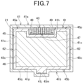
- FIG. 7 is a cross-sectional view taken along a line VII-VII in FIG. 2 (the first embodiment);
- FIG. 8 is a cross-sectional view illustrating a battery pack containing structure of a second embodiment.
- FIG. 9 is a cross-sectional view illustrating a battery pack containing structure of a third embodiment.
- FIG. 1 is a left side view illustrating a snowplow 10 according to a first embodiment of the present invention.
- the snowplow 10 includes a body frame 11 , a drive wheel axle 12 , a pair of left and right drive wheels 13 , a driven wheel axle 14 , a pair of left and right driven wheels 16 , a pair of left and right crawler belts 17 , an electric motor 18 , a battery pack 21 , a pair of left and right support members 22 , a snow displacing plate 23 , and a pair of left and right handles 24 .
- the body frame 11 is a portion constituting a framework of a machine body of the snowplow 10 .
- a power transmission mechanism (not shown) is provided at a front portion of the body frame 11 , and the drive wheel axle 12 , extending in a left-right direction of the snowplow 10 , is provided on the power transmission mechanism.
- Left and right drive wheels 13 are fixed on the drive wheel axle 12 .
- the driven wheel axle 14 is attached to a rear portion of the body frame 11 in such a manner as to extend in the left-right direction, and the left and right driven wheels 16 are rotatably attached to the driven wheel axle 14 .
- the left and right crawler belts 17 are individually extended between the drive wheel 13 and the driven wheel 16 on a left-hand side and between the drive wheel 13 and the driven wheel 16 on a right-hand side.
- the electric motor 18 is mounted at the front portion of the body frame 11 and drives the left and right drive wheels 13 via the drive wheel axle 12 . This rotates the left and right drive wheels 13 to thereby rotate the left and right crawler belts 17 , whereby the snowplow 10 is advanced or reversed to run over a running surface Gr.
- the battery pack 21 is detachably contained in an upper portion of a rear portion of the body frame 11 , and the battery pack 21 incorporates a battery (not shown) for supplying electric power to the electric motor 18 .
- the pair of left and right support members 22 extending forwards, are provided at the front portion of the body frame 11 , and the snow displacing plate 23 , configured to displace snow, is attached to front end portions of the left and right support members 22 .
- the pair of left and right handles 24 extending from the body frame 11 obliquely upwards to the rear, are attached to a rear portion of the body frame 11 .
- Grips 25 configured to be gripped on by an operator, are provided at end portions of the left and right handles 24 .
- a power supply switch 26 and a running lever 27 are provided on one of the left and right handles 24 .
- the power supply switch 26 is operated to start or stop the operation of the snowplow 10 . Switching on the power supply switch 26 actuates the electric motor 18 for operation.
- the running lever 27 controls a running speed when the snowplow 10 advances or reverses and stops the snowplow 10 . With the running lever 27 left not gripped, the snowplow 10 stops. Gripping the running lever 27 can control the running speed according to a gripping amount.
- a shift lever 28 is provided on the other of the left and right handles 24 . With the shift lever 28 , the snowplow 10 is caused to advance, reverse and stop.
- the body frame 11 is covered with a body cover 31 from above.
- the battery pack 21 which is contained in a containing portion, projects at an upper portion of a rear portion of the body cover 31 , and a projecting portion of the battery pack 21 is covered with a lid 32 , which is provided to be opened and closed on the body cover 31 .
- FIG. 2 is a cross-sectional view illustrating a battery pack containing structure of the first embodiment and taken in an up-down direction along a center line extending in a front-rear direction while passing through a transverse center of the snowplow 10 .
- a battery containing portion 41 configured to detachably contain the battery pack 21 is disposed at an upper portion of a rear portion of the body frame 11 (refer to FIG. 1 ).
- the battery containing portion 41 is formed into a box shape having an upper wall 41 a , a lower wall 41 b , a pair of left and right side walls 41 c (refer to FIG. 3 ) and a bottom wall 41 d and includes a containing portion opening 41 e through which the battery pack 21 is inserted and removed.
- the battery containing portion 41 is made from a resin and is supported on the body frame 11 .
- the upper wall 41 a and the lower wall 41 b of the battery containing portion 41 are inclined by angle ⁇ 1 relative to a vertical line 40 that extends vertically so that a containing portion opening 41 e is situated above or at the same height as the bottom wall 41 d .
- the angle ⁇ 1 is set to be in a range of 0 ⁇ 1 ⁇ 90°.
- the upper wall 41 a includes a bent back portion 41 f that extends integrally upwards from an upper edge of the containing portion opening 41 e and a pair of left and right warm air vent portions 41 g configured to release therethrough warm air inside the battery containing portion 41 to the exterior of the battery containing portion 41 in cooperation with the containing portion opening 41 e.
- An electrode portion 43 which is electrically connected with a battery pack 21 side, is provided on an upper surface 41 h that constitutes an inner surface of the upper wall 41 a.
- a plurality of drain holes 41 x and a guide groove 41 j are formed in and on the lower wall 41 b , respectively, the plurality of drain holes 41 x formed at a front edge that becomes lowest, the guide groove 41 j guiding the battery pack 21 when the battery pack 21 is caused to slide into a predetermined position inside the battery containing portion 41 for containment.
- the bottom wall 41 d includes a plurality of projecting abutment portions 41 k with which the battery pack 21 is brought into abutment, whereby a venting gap 42 is formed between the bottom wall 41 d and the battery pack 21 contained by the plurality of abutment portions 41 k.
- the battery pack 21 includes a battery case 45 , a battery 46 incorporated in the battery case 45 , and an output terminal 47 attached to an outer surface of the battery case 45 to output electric power of the battery 46 .
- the battery case 45 is formed into a box shape including an upper wall 45 a , a lower wall 45 b , a pair of left and right side walls 45 c (refer to FIG. 7 ), a front wall 45 e , and a rear wall 45 f.
- the upper wall 45 a includes a lowered wall 45 g that is formed on a side facing the front wall 45 e , a raised wall 45 h surrounding the lowered wall 45 g from the left, right and rear and formed higher than the lowered wall 45 g , and a step portion 45 j formed between the lowered wall 45 g and the raised wall 45 h.
- a pair of left and right heat dissipating portions 45 k is provided on the raised wall 45 h to promote the dissipation of heat from the battery 46 .
- the output terminal 47 is provided adjacent to the step portion 45 j.
- the lower wall 45 b includes a case projecting portion 45 m configured to be inserted slidably in the guide groove 41 j of the battery containing portion 41 .
- the rear wall 45 f integrally includes a handle 45 n gripped on by the hand, and a residual amount indicator 48 configured to indicate a residual amount of the battery 46 is provided on the rear wall 45 f situated to a side of the handle 45 n .
- the residual amount indicator 48 is made up of a plurality of light emitting portions designed so that the number of light emitting portions to be illuminated changes according to a residual amount of the battery 46 .
- a cover opening 31 a is provided at the upper portion of the rear portion of the body cover 31 , the battery containing portion 41 is inserted through the cover opening 31 a.
- a hinge portion 31 b is provided at an upper portion of the body cover 31 , and the lid 32 is attached to the hinge portion 31 b so as to be opened and closed.
- the hinge portion 31 b is made up of a hinge base portion 31 c formed on the body cover 31 and a hinge shaft 53 fixed to the hinge base portion 31 c , and one end portion 32 a of the lid 32 is supported on the hinge shaft 53 so as to swing.
- the lid 32 is a fully or partially transparent member and covers the containing portion opening 41 e of the battery containing portion 41 and one end portion of the battery pack 21 contained in the battery containing portion 41 . With the lid 32 formed fully or partially transparent, the residual amount indicator 48 of the battery pack 21 can be visible from an exterior of the snowplow 10 when the lid 32 is kept closed. The other end portion 32 b of the lid 32 can be brought into engagement with an edge portion of the cover opening 31 a of the body cover 31 via an engagement portion, not shown.
- Lids 32 X, 32 Y indicated by chain double-dashed lines in the drawing indicate the lid 32 that is held in an open state by a holding structure, not shown.
- the lid 32 X stays in a fully open state.
- the other end portion 32 b of the lid 32 X is situated behind a vertical line 40 passing through an upper edge of the containing portion opening 41 e of the battery containing portion 41 (that is, on an upper side of the containing portion opening 41 e than the vertical line 40 ).
- the lid 32 Y is situated at an intermediate portion between the fully closed lid 32 and the fully opened lid 32 X. In the lid 32 Y staying in the intermediate position, the other end portion 32 b of the lid 32 Y is situated above an extension 55 of an upper surface 45 p of the upper wall 45 a of the battery pack 21 .
- FIG. 3 is a view illustrating the upper surface 41 h that constitutes the inner surface of the upper wall 41 a of the battery containing portion 41 (the first embodiment)
- FIG. 4 is a view illustrating the lower surface 41 p constituting the inner surface of the lower wall 41 b of the battery containing portion 41 (the first embodiment).
- the battery pack 21 is indicated by chain double-dashed lines.
- the upper wall 41 a of the battery containing portion 41 includes a lowered wall 41 q , a raised wall 41 r , and a step portion 41 s.
- the lowered wall 41 q is formed at a transverse center of the upper wall 41 a in such a manner as to extend in a front-rear direction (in a longitudinal direction of the battery pack 21 ).
- An upper surface 41 t constituting an inner surface of the lowered wall 41 q is formed flat.
- the raised wall 41 r is formed at the left, right and rear of the lowered wall 41 q and is formed taller than the lowered wall 41 q .
- the step portion 41 s is a portion extending in the up-down direction in such a manner as to connect the lowered wall 41 q and the raised wall 41 r together.
- the electrode portion 43 projecting from an upper surface 41 u of the raised wall 41 r , is disposed at an end portion of the lowered wall 41 q that is situated at a side facing the containing portion opening 41 e (refer to FIG. 2 ).
- the warm air vent portions 41 g are individually provided in the raised wall 41 r at the left and right of the lowered wall 41 q , specifically speaking, in the upper surface 41 u constituting an inner surface of the raised wall 41 r .
- a groove 41 m extending into a V-like shape in the left-right direction, is formed between the containing portion opening 41 e and the electrode portion 43 on the upper surface 41 u of the raised wall 41 r at the rear of the lowered wall 41 q .
- the groove 41 m is formed along a full width of the upper surface 41 u.
- the upper surface 41 h of the upper wall 41 a is made up of the upper surface 41 t and the upper surface 41 u , which are described above.
- the electrode portion 43 is made up of a plurality of plate-like terminals connected to an electric motor 18 (refer to FIG. 1 ) side, and the plurality of terminals extend individually in a direction in which the battery pack 21 is installed and removed (in the front-rear direction) and are arranged side by side in the left-right direction at predetermined intervals.
- the left and right warm air vent portions 41 g are made up, respectively, of a pair of left and right containing portion vent holes 41 n formed in the upper wall 41 a and mesh members 57 individually covering the corresponding left and right containing portion vent holes 41 n.
- the left and right containing portion vent holes 41 n penetrate the upper wall 41 a .
- Each of the mesh members 57 is made of metal or resin, has a plurality of fine meshes and is attached to an edge of the containing portion vent hole 41 n .
- the plurality of meshes prevents sand or dust from entering the interior of the battery containing portion 41 from the exterior and allows warm air in the interior of the battery containing portion 41 to be released to the exterior.
- Warm air discharged from the warm air vent portions 41 g to the exterior of the battery containing portion 41 is then discharged to an exterior of the snowplow 10 (refer to FIG. 1 ) from vent openings (not shown) disposed at other locations than above the battery containing portion 41 of the body cover 31 (refer to FIG. 1 ).
- the warm air vent portions 41 g are covered thereabove with the body cover 31 , whereby rain water, snow, and melting snow are prevented from entering the interior of the battery containing portion 41 from the warm air vent portions 41 g .
- the containing portion vent holes 41 n are formed at the longitudinally central portion of the upper wall 41 a , the configuration is not limited thereto, and hence, the containing portion vent holes 41 n may be formed closer to a rear portion of the upper wall 41 a where warm air is easily discharged.
- the groove 41 m constitutes a portion configured to prevent rain water and melting snow that flows from the containing portion opening 41 e along the upper surface 41 h (specifically, the upper surface 41 u of the raised wall 41 r ) of the upper wall 41 a from reaching the electrode portion 43 .
- the groove 41 m is formed into the V-like shape in which transverse left and right ends (opened portions of the V-like shape) are situated on a lower side (a front) of the upper surface 41 h than a transverse center (a closed portion of the V-like shape).
- the groove 41 m By forming the groove 41 m into the V-like shape in the way described above, rain water and melting snow flow to the transverse left and eight ends of the upper surface 41 h (specifically, the upper surface 41 u ) along the groove 41 m and then flow to the lower wall 41 b (refer to FIG. 4 ) via the left and right side walls 41 c . As a result, rain water and melting snow can be prevented from adhering to the electrode portion 43 by the groove 41 m.
- the plurality of drain holes 41 x configured to discharge water entering the interior of the battery containing portion 41 to the exterior, are formed at the front edge of the lower surface 41 p of the battery containing portion 41 .
- the guide groove 41 j is formed on the lower surface 41 p of the battery containing portion 41 in such a manner as to extend in the direction in which the battery pack 21 is installed and removed (in the front-rear direction) while passing through the transverse center of the lower surface 41 p .
- the case projecting portion 45 m (refer to FIG. 6 ) of the battery pack 21 is slidably inserted into the guide groove 41 j.
- FIG. 5 is a view illustrating the upper surface 45 p of the upper wall 45 a of the battery pack 21 (the first embodiment)
- FIG. 6 is a view illustrating the lower surface 45 q of the lower wall 45 b of the battery pack 21 (the first embodiment).
- the upper surface 45 p of the upper wall 45 a is made up of an upper surface 45 r of the lowered wall 45 g and an upper surface 45 s of the raised wall 45 h.
- the output terminal 47 is provided at an end portion of the upper surface 45 r of the lowered wall 45 g , the end portion situated to face the handle 45 n.
- the output terminal 47 is made up of the plurality of plate-like terminals connected with the battery 46 , and the plurality of terminals each extend in the direction in which the battery pack 21 is installed and removed (in the front-rear direction) and are arranged side by side in the left-right direction at the predetermined intervals.
- the output terminal 47 may be covered from left and right sides thereof by a pair of left and right projecting walls 49 formed on the upper surface 45 r .
- the output terminal 47 can be protected by the left and right projecting walls 49 .
- a pair of left and right heat dissipating portions 45 k and a groove 45 u extending in the left-right direction are provided on the upper surface 45 s of the raised wall 45 h.
- the left and right heat dissipating portions 45 k are made up, respectively, of a pair of left and right battery pack vent holes 45 t formed in the upper wall 45 a (specifically, a longitudinally central portion of the upper wall 45 a ) and mesh members 58 individually covering the corresponding left and right battery pack vent holes 45 t.
- the left and right battery pack vent holes 45 t penetrate the upper wall 45 a and communicate with a containing portion of the battery 46 in the battery pack 21 .
- Each of the mesh members 58 is made of metal or resin, has a plurality of fine meshes and is attached to an edge of the corresponding battery pack vent hole 45 t .
- the plurality of meshes prevents sand or dust from entering the interior of the battery case 45 from the exterior and allows warm air generated by heat of the battery 46 in the battery case 45 to be released to the battery containing portion 41 .
- the groove 45 u constitutes a portion configured to prevent rain water and melting snow that flows from the containing portion opening 41 e (refer to FIG. 2 ) along the upper surface 45 s of the upper wall 45 a from reaching the output terminal 47 .
- the groove 45 u is formed into a V-like shape in which transverse left and right ends (opened portions of the V-like shape) are situated on a lower side (a front) of the upper surface 45 s than a transverse center (a closed portion of the V-like shape) and is formed along an overall width of the upper surface 45 s.
- the case projecting portion 45 m is formed on the lower surface 45 q of the battery pack 21 in such a manner as to extend in the direction in which the battery pack 21 is installed and removed (in the front-rear direction) while passing through a transverse center.
- the case projecting portion 45 m is slidably inserted in the guide groove 41 j (refer to FIG. 4 ).
- the grooves 41 m , 45 u as the recessed portions or projecting portions configured to block the flow of water to the electrode portion 43 or the output terminal 47 of the battery 46 are provided on the upper surface (the internal upper surface) 41 h of the battery containing portion 41 in the position situated closer to the containing portion opening 41 e than the electrode portion 43 or on the upper surface 45 p of the battery pack 21 in the position situated closer to the containing portion opening 41 e than the output terminal 47 as the terminal of the battery 46 of the battery pack 21 contained in the battery containing portion 41 .
- the grooves 41 m , 45 u or the projecting portions are both formed into the V-like shape.
- the closed portion of the V-like shape is situated at a side of the battery containing portion 41 and the battery pack 21 contained in the battery containing portion 41 with the side situated to face the containing portion opening 41 e
- the open portion of the V-like shape is situated at a side of the battery containing portion 41 with the side situated to face the bottom wall 41 d as the bottom portion of the battery containing portion 41
- the guide groove 41 j configured to guide the slide of the battery pack 21 that incorporates the battery 46 is provided on the lower surface (the internal lower surface) 41 p of the battery containing portion 41 .
- the battery pack 21 includes the heat dissipating portions 45 k on the upper surface 45 p .
- the battery containing portion 41 includes the warm air vent portions 41 g provided on the upper surface 41 h in such a manner as to be opposite to the heat dissipating portions 45 k of the battery pack 21 . Warm air generated by heat dissipated from the battery 46 is discharged to the exterior of the battery containing portion 41 via the warm air vent portions 41 g.
- warm air generated from the battery 46 can efficiently be discharged from the battery containing portion 41 to the exterior.
- FIG. 7 is a cross-sectional view taken along a line VII-VII in FIG. 2 (the first embodiment).
- a gap 61 is provided between the upper surface 41 h of the battery containing portion 41 and the upper surface 45 p of the battery pack 21 , and gaps 62 are individually provided between the left and right side walls 41 c of the battery containing portion 41 and the left and right side walls 45 c of the battery pack 21 .
- a gap 42 is provided between the bottom wall 41 d of the battery containing portion 41 and the front wall 45 e of the battery pack 21 .
- the lower surface 45 q of the battery pack 21 slides on the lower surface 41 p of the battery containing portion 41 .
- a projecting portion extending in the direction in which the battery pack 21 is installed and removed, may be provided on the lower surface 41 p of the battery containing portion 41 or the lower surface 45 q of the battery pack 21 to thereby form a gap between the lower surfaces 41 p , 45 q . This can promote further the convection of warm air in the interior of the battery containing portion 41 described above.
- the electrically driven snowplow 10 as the working machine includes the battery pack 21 incorporating the battery 46 , the battery containing portion 41 disposed so that the battery pack 21 can be inserted and removed in the direction inclined from the vertical direction, and the electrode portion 43 disposed on the upper surface 41 h of the battery containing portion 41 for connection with the output terminal 47 of the battery 46 .
- the electrode portion 43 is disposed further inwards of the battery containing portion 41 than the vertical line 40 passing through the upper edge of the containing portion opening 41 e of the battery containing portion 41 .
- bent back portion 41 f is provided on the side of the battery containing portion 41 , the side situated closer to the containing portion opening 41 e than the electrode portion 43 , rain water, snow and melting snow can be blocked by the bent back portion 41 f to thereby be prevented from adhering to the electrode portion 43 and the output terminal 47 .
- the containing portion opening 41 e of the battery containing portion 41 is covered with the lid 32 that can be opened and closed, and the other end portion 32 b of the lid 32 as the distal end portion thereof is situated closer to the containing portion opening 41 e than the vertical line 40 that passes through the upper edge of the containing portion opening 41 e of the battery containing portion 41 in the fully openable and closable range of the lid 32 .
- rain water, snow and melting snow can be restrained further from entering the interior of the battery containing portion 41 from the containing portion opening 41 e by the lid 32 , whereby rain water, snow and melting snow can be prevented from adhering to the output terminal 47 of the battery 46 and the electrode portion 43 .
- FIG. 8 is a cross-sectional view illustrating a battery pack containing structure of a second embodiment.
- a battery pack containing structure of a snowplow 70 illustrated in FIG. 8 differs from the battery pack containing structure of the snowplow 10 of the first embodiment illustrated in FIG. 2 in the structure of a battery containing portion 71 , the structure of a body cover 73 and in that the lid 32 (refer to FIG. 3 ) is not provided.
- like reference signs will be given to like structures to those of the first embodiment, and the description thereof will be omitted.
- the battery containing portion 71 is formed into a box shape including an upper wall 71 a , a lower wall 41 b , a pair of left and right side walls 41 c (refer to FIG. 3 ) and a bottom wall 41 d and includes a containing portion opening 41 e through which a battery pack 21 is inserted and removed.
- the battery containing portion 71 is made from a resin and is supported on a body frame 11 (refer to FIG. 1 ). As with the first embodiment, the upper wall 71 a and the lower wall 41 b of the battery containing portion 71 are inclined by angle ⁇ 1 (refer to FIG. 2 ) relative to a vertical line 75 that extends vertically so that a containing portion opening 41 e is situated above or at the same height as the bottom wall 41 d.
- the upper wall 71 a includes an integrated penthouse portion 71 b configured to cover the containing portion opening 41 e from above, a pair of left and right warm air vent portions 41 g configured to release warm air in an interior of the battery containing portion 71 to an exterior of the battery containing portion 71 in cooperation with the containing portion opening 41 e , and a groove 41 m.
- An electrode portion 43 is provided on an upper surface 41 h constituting an inner surface of the upper wall 71 a for electrical connection with a battery pack 21 side.
- a cover opening 31 a is opened in an upper portion of a rear portion of a body cover 73 configured to cover over the body frame 11 , and the battery containing portion 71 is inserted through the cover opening 31 a.
- the penthouse portion 71 b extends from the cover opening 31 a of the body cover 73 obliquely upwards to the rear, and a distal end portion 71 c of the penthouse portion 71 b is situated behind a vertical line 75 extending vertically while passing through a lower edge of the containing portion opening 41 e.
- FIG. 9 is a cross-sectional view illustrating a battery pack containing structure of a third embodiment.
- the battery pack containing structure illustrated in FIG. 9 differs from the battery pack containing structure of the first embodiment illustrated in FIG. 2 in the structure of a battery containing portion 81 and the structure of a battery pack 82 .
- like reference signs will be given to like structures to those of the first embodiment, and the description thereof will be omitted.
- the battery containing portion 81 where the battery pack 82 is detachably contained is disposed at an upper portion of a rear portion of the body frame 11 (refer to FIG. 1 ).
- the battery containing portion 81 is formed into a box shape including an upper wall 81 a , a lower wall 81 b , a pair of left and right side walls 41 c (refer to FIG. 7 ) and a bottom wall 41 d and includes a containing portion opening 81 e through which a battery pack 82 is inserted and removed.
- the battery containing portion 81 is made from a resin and is supported in the body frame 11 .
- the upper wall 81 a and the lower wall 81 b of the battery containing portion 81 are inclined by an angle ⁇ 2 relative to a horizontal line 80 A extending horizontally so that the containing portion opening 81 e is situated below the bottom wall 41 d .
- the angle ⁇ 2 is set to be in a range of 0 ⁇ 2 ⁇ 45°, and preferably, the angle ⁇ 2 is set to be in a range of 0 ⁇ 2 ⁇ 30°.
- the containing portion opening 81 e is formed vertically or substantially vertically along a vertical line 80 B.
- the upper wall 81 a includes a plurality of warm air vent portions 41 g , 81 g configured to release warm air in an interior of the battery containing portion 81 to an exterior of the battery containing portion 81 .
- a pair of left and right warm air vent portions 81 g is formed at an edge portion of the upper wall 81 a , the edge portion situated on a side facing the bottom wall 41 d , and the warm air vent portions 81 g each have the same structure as that of the warm air vent portion 41 g.
- An electrode portion 43 configured to be electrically connected with a battery pack 82 side, is provided on an upper surface 81 h constituting an inner surface of the upper wall 81 a .
- An engagement portion 84 configured to be brought into engagement with the battery pack 82 inserted into the battery containing portion 81 , is provided on an outer surface 81 j of the upper wall 81 a.
- the engagement portion 84 includes a plate-like elastic member 86 that is attached to the upper wall 81 a with a plurality of machine screws 85 and a hook portion 87 that is provided on the elastic member 86 .
- a finger hook portion 86 a designed for the finger to be hooked, is provided at an end portion of the elastic member 86 .
- a guide groove 41 j configured to guide the battery pack 82 when the battery pack 82 is caused to slide into a predetermined position in the interior of the battery containing portion 81 for containment, is formed on the lower wall 81 b.
- the battery pack 82 includes a battery case 91 , a battery 46 incorporated in the battery case 91 , and an output terminal 47 attached to an outer surface of the battery case 91 to output electric power of the battery 46 .
- the battery case 91 does not include the groove 45 u on the upper wall 45 a of the battery case 45 of the first embodiment, and a handle 91 n has a different shape from that of the handle 45 n of the first embodiment.
- the battery case 91 is formed into a box shape including an upper wall 91 a , a lower wall 45 b , a pair of left and right side walls 45 c (refer to FIG. 7 ), a front wall 45 e and a rear wall 45 f.
- the upper wall 91 a includes a lowered wall 45 g , a raised wall 91 h formed taller than the lowered wall 45 g , and a step portion 45 j formed between the lowered wall 45 g and the raised wall 91 h.
- a pair of left and right heat dissipating portions 91 k configured to promote the dissipation of heat from the battery 46 , is provided in the raised wall 91 h.
- the rear wall 45 f integrally includes the handle 91 n that is gripped on by the hand, and a residual amount indicator 48 , configured to indicate a residual amount of the battery 46 , is provided on the rear wall 45 f situated at a side of the handle 91 n.
- the handle 91 n includes a notched portion 91 p formed on a side facing the raised wall 91 h so that the hook portion 87 of the engagement portion 84 can be brought into engagement therewith.
- the hook portion 87 of the engagement portion 84 is biased by the elastic member 86 and is kept in engagement with the notched portion 91 b on the handle 91 n.
- the upper wall 81 a and the lower wall 81 b of the battery containing portion 81 are inclined relative to the horizontal line 80 A so that the containing portion opening 81 e is situated below the bottom wall 41 d .
- This can make it difficult for rain water and snow to enter the interior of the battery containing portion 81 , and even though rain water and snow enter the interior of the battery containing portion 81 , rain water and snow can be discharged from the interior of the battery containing portion 81 quickly.
- rain water and snow can be prevented from adhering to the electrode portion 43 of the battery containing portion 81 and the output terminal 47 of the battery pack 82 .
- the battery containing portion 41 and the battery 46 are inclined rearwards relative to the vertical line 40 ; however, the configuration is not limited thereto, and hence, the battery containing portion 41 and the battery 46 (and hence, the battery pack 21 ) may be inclined transversely relative to the vertical line 40 .
- the groove 41 m as the recessed portion is formed on the upper surface 41 h of the battery containing portion 41
- the groove 45 u as the recessed portion is formed on the upper surface 45 p of the battery pack 21 ; however, the configuration is not limited thereto.
- a V-like projecting portion may be formed on each of the upper surface 41 h of the battery containing portion 41 and the upper surface 45 p of the battery pack 21 in place of the grooves 41 m , 45 u.
- the snowplow is described as being the working machine; however, the structure of the present invention can also be applied to other working machines (for example, a lawn mower, a rotary tiller, a water pump, a conveyor robot, and the like).
Landscapes
- Engineering & Computer Science (AREA)
- Chemical & Material Sciences (AREA)
- Chemical Kinetics & Catalysis (AREA)
- Electrochemistry (AREA)
- General Chemical & Material Sciences (AREA)
- Manufacturing & Machinery (AREA)
- Power Engineering (AREA)
- Sustainable Energy (AREA)
- Sustainable Development (AREA)
- Transportation (AREA)
- Mechanical Engineering (AREA)
- Life Sciences & Earth Sciences (AREA)
- Architecture (AREA)
- Civil Engineering (AREA)
- Structural Engineering (AREA)
- Battery Mounting, Suspending (AREA)
- Cleaning Of Streets, Tracks, Or Beaches (AREA)
- Secondary Cells (AREA)
Abstract
Description
- Patent Literature 1
- Patent Literature 2
Claims (10)
Applications Claiming Priority (3)
| Application Number | Priority Date | Filing Date | Title |
|---|---|---|---|
| JP2018-126076 | 2018-07-02 | ||
| JP2018126076A JP7046739B2 (en) | 2018-07-02 | 2018-07-02 | Working machine |
| JPJP2018-126076 | 2018-07-02 |
Publications (2)
| Publication Number | Publication Date |
|---|---|
| US20200001729A1 US20200001729A1 (en) | 2020-01-02 |
| US11731518B2 true US11731518B2 (en) | 2023-08-22 |
Family
ID=69007907
Family Applications (1)
| Application Number | Title | Priority Date | Filing Date |
|---|---|---|---|
| US16/424,962 Active 2040-02-17 US11731518B2 (en) | 2018-07-02 | 2019-05-29 | Working machine |
Country Status (2)
| Country | Link |
|---|---|
| US (1) | US11731518B2 (en) |
| JP (1) | JP7046739B2 (en) |
Cited By (1)
| Publication number | Priority date | Publication date | Assignee | Title |
|---|---|---|---|---|
| US20230114884A1 (en) * | 2021-10-13 | 2023-04-13 | Briggs & Stratton, Llc | Zero turn radius mower with removable battery packs |
Families Citing this family (8)
| Publication number | Priority date | Publication date | Assignee | Title |
|---|---|---|---|---|
| WO2020236787A1 (en) * | 2019-05-20 | 2020-11-26 | Techtronic Cordless Gp | Snow thrower |
| JP7584921B2 (en) * | 2020-06-24 | 2024-11-18 | ダイヤゼブラ電機株式会社 | Battery unit heat dissipation structure |
| DE112020007737T5 (en) * | 2020-10-30 | 2023-09-28 | Honda Motor Co., Ltd. | WORK VEHICLE |
| JP7754690B2 (en) | 2021-01-25 | 2025-10-15 | 本田技研工業株式会社 | electric work equipment |
| JP7623875B2 (en) * | 2021-03-31 | 2025-01-29 | 本田技研工業株式会社 | Retaining device |
| US12362419B2 (en) * | 2021-12-22 | 2025-07-15 | Techtronic Cordless Gp | Circular saw with drain feature |
| GB2626528B (en) * | 2023-01-19 | 2025-05-07 | Caterpillar Sarl | Electric excavator with power store housing |
| CN117374470B (en) * | 2023-12-07 | 2024-02-27 | 新乡市鸿晟能源有限公司 | Communication lithium battery pack based on AGV robot |
Citations (14)
| Publication number | Priority date | Publication date | Assignee | Title |
|---|---|---|---|---|
| US6056077A (en) * | 1996-11-20 | 2000-05-02 | Yamaha Hatsudoki Kabushiki Kaisha | Small vehicle |
| US6566005B1 (en) * | 1999-11-10 | 2003-05-20 | Makita Corporation | Battery pack with an improved cooling structure |
| US20040031632A1 (en) * | 2002-08-16 | 2004-02-19 | Hideo Kohda | Battery mounting arrangement for electrically powered vehicle |
| US20050202310A1 (en) * | 2003-10-03 | 2005-09-15 | Yahnker Christopher R. | Thermal management systems for battery packs |
| US20110056177A1 (en) * | 2009-09-10 | 2011-03-10 | Makita Corporation | Electric wheeled apparatus |
| US20120045671A1 (en) * | 2010-08-20 | 2012-02-23 | William Miller | Battery pack including a support frame |
| JP2012099383A (en) | 2010-11-04 | 2012-05-24 | Makita Corp | Battery pack |
| US20120316477A1 (en) * | 2011-06-10 | 2012-12-13 | Sanyo Electric Co., Ltd. | Battery pack encasing structure and walking assistance device using same |
| JP2013021952A (en) | 2011-07-19 | 2013-02-04 | Kubota Corp | Walking type electric working implement |
| US20130239533A1 (en) * | 2012-03-07 | 2013-09-19 | Robert Bosch Gmbh | Lawn-care apparatus |
| JP2014141853A (en) | 2013-01-25 | 2014-08-07 | Sasaki Corporation | Electrically-driven blade snow remover |
| JP2016049048A (en) * | 2014-08-29 | 2016-04-11 | 株式会社マキタ | Lawn mower |
| CN107919445A (en) | 2016-10-11 | 2018-04-17 | 天佑电器(苏州)有限公司 | Battery pack assembly and there is its garden instrument |
| WO2019062795A1 (en) * | 2017-09-27 | 2019-04-04 | 宝时得科技(中国)有限公司 | Self-mobile device and automatic working system thereof |
Family Cites Families (2)
| Publication number | Priority date | Publication date | Assignee | Title |
|---|---|---|---|---|
| JP2014147353A (en) | 2013-02-01 | 2014-08-21 | Makita Corp | Electric lawn mower |
| JP2018092746A (en) | 2016-11-30 | 2018-06-14 | 本田技研工業株式会社 | Battery mounting structure |
-
2018
- 2018-07-02 JP JP2018126076A patent/JP7046739B2/en active Active
-
2019
- 2019-05-29 US US16/424,962 patent/US11731518B2/en active Active
Patent Citations (17)
| Publication number | Priority date | Publication date | Assignee | Title |
|---|---|---|---|---|
| US6056077A (en) * | 1996-11-20 | 2000-05-02 | Yamaha Hatsudoki Kabushiki Kaisha | Small vehicle |
| US6566005B1 (en) * | 1999-11-10 | 2003-05-20 | Makita Corporation | Battery pack with an improved cooling structure |
| US20040031632A1 (en) * | 2002-08-16 | 2004-02-19 | Hideo Kohda | Battery mounting arrangement for electrically powered vehicle |
| US20050202310A1 (en) * | 2003-10-03 | 2005-09-15 | Yahnker Christopher R. | Thermal management systems for battery packs |
| US20110056177A1 (en) * | 2009-09-10 | 2011-03-10 | Makita Corporation | Electric wheeled apparatus |
| JP2011079510A (en) | 2009-09-10 | 2011-04-21 | Makita Corp | Electric vehicle |
| US20120045671A1 (en) * | 2010-08-20 | 2012-02-23 | William Miller | Battery pack including a support frame |
| JP2012099383A (en) | 2010-11-04 | 2012-05-24 | Makita Corp | Battery pack |
| US20120316477A1 (en) * | 2011-06-10 | 2012-12-13 | Sanyo Electric Co., Ltd. | Battery pack encasing structure and walking assistance device using same |
| JP2013016449A (en) | 2011-06-10 | 2013-01-24 | Honda Motor Co Ltd | Battery pack housing structure and battery pack and walking auxiliary apparatus |
| JP2013021952A (en) | 2011-07-19 | 2013-02-04 | Kubota Corp | Walking type electric working implement |
| US20130239533A1 (en) * | 2012-03-07 | 2013-09-19 | Robert Bosch Gmbh | Lawn-care apparatus |
| JP2014141853A (en) | 2013-01-25 | 2014-08-07 | Sasaki Corporation | Electrically-driven blade snow remover |
| JP2016049048A (en) * | 2014-08-29 | 2016-04-11 | 株式会社マキタ | Lawn mower |
| CN107919445A (en) | 2016-10-11 | 2018-04-17 | 天佑电器(苏州)有限公司 | Battery pack assembly and there is its garden instrument |
| WO2019062795A1 (en) * | 2017-09-27 | 2019-04-04 | 宝时得科技(中国)有限公司 | Self-mobile device and automatic working system thereof |
| US20200267903A1 (en) * | 2017-09-27 | 2020-08-27 | Positec Technology (China) Co., Ltd | Self-moving device and automatic working system thereof |
Non-Patent Citations (2)
| Title |
|---|
| Japanese Office Action with English translation dated Nov. 9, 2021, 9 pages. |
| Machine translation of Kamiya et al. JP 2016/049048. Originally published Apr. 11, 2016 (Year: 2016). * |
Cited By (1)
| Publication number | Priority date | Publication date | Assignee | Title |
|---|---|---|---|---|
| US20230114884A1 (en) * | 2021-10-13 | 2023-04-13 | Briggs & Stratton, Llc | Zero turn radius mower with removable battery packs |
Also Published As
| Publication number | Publication date |
|---|---|
| JP2020004683A (en) | 2020-01-09 |
| US20200001729A1 (en) | 2020-01-02 |
| JP7046739B2 (en) | 2022-04-04 |
Similar Documents
| Publication | Publication Date | Title |
|---|---|---|
| US11731518B2 (en) | Working machine | |
| JP6509060B2 (en) | Mowing machine | |
| KR101210325B1 (en) | Electric cultivator | |
| EP3778133B1 (en) | Electric working tool | |
| US11701769B2 (en) | Electric working tool | |
| US20090236876A1 (en) | Tractor | |
| CN105309093B (en) | Working machine | |
| CN108496535B (en) | Combine harvester | |
| JP6556049B2 (en) | Walking blade working machine | |
| US7108089B2 (en) | Walk-behind self-propelled working machine | |
| JP2013060157A (en) | Vehicle body front structure of vehicle | |
| US20180334119A1 (en) | Work vehicle | |
| EP4454915A1 (en) | Electric work vehicle | |
| JP2023048569A (en) | Work equipment breather structure | |
| JP6604913B2 (en) | Work vehicle | |
| JP2012158235A (en) | Motive power part structure of combined harvester | |
| JP3132768U (en) | Protective plate | |
| JP4471616B2 (en) | Combine | |
| JP6606463B2 (en) | Work vehicle | |
| JP7723832B2 (en) | Work equipment | |
| JP2000245235A (en) | Driving unit structure of combine | |
| JP2007319091A (en) | Combine | |
| WO2023175952A1 (en) | Snowblower | |
| JP7362456B2 (en) | construction machinery | |
| JP2024018596A (en) | work vehicle |
Legal Events
| Date | Code | Title | Description |
|---|---|---|---|
| AS | Assignment |
Owner name: HONDA MOTOR CO., LTD., JAPAN Free format text: ASSIGNMENT OF ASSIGNORS INTEREST;ASSIGNORS:MATSUYAMA, WATARU;ENOMOTO, TAKAYUKI;YAMANAKA, MAKOTO;REEL/FRAME:049306/0076 Effective date: 20190408 |
|
| FEPP | Fee payment procedure |
Free format text: ENTITY STATUS SET TO UNDISCOUNTED (ORIGINAL EVENT CODE: BIG.); ENTITY STATUS OF PATENT OWNER: LARGE ENTITY |
|
| STPP | Information on status: patent application and granting procedure in general |
Free format text: DOCKETED NEW CASE - READY FOR EXAMINATION |
|
| STPP | Information on status: patent application and granting procedure in general |
Free format text: NON FINAL ACTION MAILED |
|
| STPP | Information on status: patent application and granting procedure in general |
Free format text: RESPONSE TO NON-FINAL OFFICE ACTION ENTERED AND FORWARDED TO EXAMINER |
|
| STPP | Information on status: patent application and granting procedure in general |
Free format text: FINAL REJECTION MAILED |
|
| STPP | Information on status: patent application and granting procedure in general |
Free format text: ADVISORY ACTION MAILED |
|
| STPP | Information on status: patent application and granting procedure in general |
Free format text: DOCKETED NEW CASE - READY FOR EXAMINATION |
|
| STPP | Information on status: patent application and granting procedure in general |
Free format text: NON FINAL ACTION MAILED |
|
| STPP | Information on status: patent application and granting procedure in general |
Free format text: RESPONSE TO NON-FINAL OFFICE ACTION ENTERED AND FORWARDED TO EXAMINER |
|
| STPP | Information on status: patent application and granting procedure in general |
Free format text: FINAL REJECTION MAILED |
|
| STPP | Information on status: patent application and granting procedure in general |
Free format text: NOTICE OF ALLOWANCE MAILED -- APPLICATION RECEIVED IN OFFICE OF PUBLICATIONS |
|
| STPP | Information on status: patent application and granting procedure in general |
Free format text: PUBLICATIONS -- ISSUE FEE PAYMENT RECEIVED |
|
| STCF | Information on status: patent grant |
Free format text: PATENTED CASE |