US1171663A - Railway-car. - Google Patents
Railway-car. Download PDFInfo
- Publication number
- US1171663A US1171663A US87543514A US1914875435A US1171663A US 1171663 A US1171663 A US 1171663A US 87543514 A US87543514 A US 87543514A US 1914875435 A US1914875435 A US 1914875435A US 1171663 A US1171663 A US 1171663A
- Authority
- US
- United States
- Prior art keywords
- strip
- car
- strips
- named
- strengthening
- Prior art date
- Legal status (The legal status is an assumption and is not a legal conclusion. Google has not performed a legal analysis and makes no representation as to the accuracy of the status listed.)
- Expired - Lifetime
Links
- 238000005728 strengthening Methods 0.000 description 32
- 239000002184 metal Substances 0.000 description 22
- 238000010276 construction Methods 0.000 description 6
- 210000003195 fascia Anatomy 0.000 description 3
- 229910000831 Steel Inorganic materials 0.000 description 2
- 230000003014 reinforcing effect Effects 0.000 description 2
- 239000010959 steel Substances 0.000 description 2
- 241001505295 Eros Species 0.000 description 1
- 241001408653 Siona Species 0.000 description 1
- 150000001450 anions Chemical class 0.000 description 1
- 238000009408 flooring Methods 0.000 description 1
- 238000007689 inspection Methods 0.000 description 1
- 150000002500 ions Chemical class 0.000 description 1
- 229920000136 polysorbate Polymers 0.000 description 1
- 239000002023 wood Substances 0.000 description 1
Images
Classifications
-
- B—PERFORMING OPERATIONS; TRANSPORTING
- B61—RAILWAYS
- B61D—BODY DETAILS OR KINDS OF RAILWAY VEHICLES
- B61D17/00—Construction details of vehicle bodies
- B61D17/04—Construction details of vehicle bodies with bodies of metal; with composite, e.g. metal and wood body structures
- B61D17/06—End walls
Definitions
- t is another ⁇ olijeotfof my invention to rove cars" in' vsundry ⁇ details hereinciter
- the means by whichl have accomplished 'i these objects areillustrated inftheaccompa. nying drawings and are hereinafter speciy cally described. v.
- Fig. 2 is t. an'enlarged detail, being substantially a seci tion taken on line22 ⁇ of Fig; Fig. is lan enlarged ⁇ detail; ⁇ being substantially a sectiontakenen lineB-' of Figl. l
- the ycar is provided on its sides with vertically-extending side sheathing 19 and at y.its ends with vertically-extending end sheathing 20.
- a deck 21 is provided by the use of laterally-extending flooring boards inasmuch as this construction iis 1* i well known in the art, it is not believed to y est ⁇ extending between the side sills 11 and suitably supported intermediately in any ⁇ appro- ⁇ priate manner.
- Grain-strips 22, of any suit- 4 able type, are used at the juncture between the side sheathing and the deck 21.
- Anend fascia 23 is provided covering the upper ⁇ ⁇ ends of the endl sheathing boards 20, i
- Corning now to my improved strengtheni Ving means, 24 indicates a strip of 'pressed V steel extending in horizontal position across the end of the car opposite the belt rail 12,4 i'
- 26-27 indicate strengthening tormed of pressed stoel extending across-the ⁇ -end of the cur in vertical position opposite the end posts y18, the loivei-"ends of said strips strips 26--27 being secured to the end sill 10 i by means of bolts 28.
- said 'strips 26-27 are offset outwardV so as to fit snugly against said strip and against the end of the car.v
- the strips 26-27 are also oset to tit snugly about the fasciaf23.' As shown clearly in Fig.
- eacho ⁇ the strips 2li-L27 is provided with a strengthening rib or corrugation 29 pressed therein longitudis nally thereof, said ribs 29 being fadedjat their upper ends into the offset portionsof the upper ends of the strips.
- Tlfie' ⁇ strip 24 is provided with strengthening ribs or corrugations SSO extending between the strips ⁇ .2G-27 and from said strips 264-27 ,toward the ends ofthe strip 24;.
- T e strips 265-27 are secured to the strip 24 and to t e end of the car by means of bolts 31 whic inthe so).
- end sills 10,-#corner posts 1'( and end posts 'r xrail 12 as shown in Fig. 3.
- 'ff 32 indicates a strengthening strip of pressed steel extending across the fascia 23, 'jhaving its ends turned forward along the sides of the car where it is secured in position by bolts 33 passing vthrough the side plates 13'. At the points Where the strip 32' extends across the upper ends of the strips 2(5*27 the strip 32 is offset to iit snugl,
- the strip 32 has pressed therein longitudinally thereof a strengthening rib or corrugation 35 by which the strip is given the maximum longitudinal strength.
- vAs will be seen from an inspection of Fig. l, at the points Where the strips 26-27 are offset about the strip 24 and at the points where the strip 32 is offset about the strips 2G-27, the offset, in the construction showngd y 1s pressed in the bearing faces only of such" strips, leaving the outer edges of the strengthening ribs smooth and uniform.
- a device for strengthen-ing the end of a car, the combination of a metal strip secured across the outer face of the car end and provided With a strengthening rib pressed in the strip longitudinally thereof, and a second metal strip secured across the outer face of the car end at an angle to said first-named strip and extending under the said first-named strip vand under the strengthening rib thereof, said second strip being provided with strengthening ribs pressed therein longitudinally of said strip at opposite sides of its point of contact .With said first-named strip.
- al device for strengthening the end ⁇ of a car the combination of a metal strip secured across the outer-face of the car end' and provided with a strengthening rib pressed in the strip longitudinally thereof,
- a device for strengtheningv the end of a car the combination of a metal strip' secured in a horizontal positlon across the end of the car, and another metal strip secured in Vertical position across the outer face of the car end and across said horizontally-extending strip, said second-named strip being provided with a vertically-extending strengthening rib pressed therein, and said iirstr-named stripv being provided with horizontally-extending strengthening ribs pressed therein at opposite sides of said second-named strip, and means for securing said strips together at their crossing point independently of the said ribs.
- a device for strengthening the end of a car the combination of a metal strip secured across the outer face of the car end, and a plurality of other metal strips each secured acrossthe outer face of the car end and the outer face of said first-named strip and each provided with a strengthening rib pressed therein longitudinally of the rstrip across said first-named strip, said firstnamed strip being provided with strengthening ribs pressed therein longitudinally'of the strip both between said second-named strips and also from ⁇ said second-named strips'toward the ends of the first-named strip.
- a metal vstrip secured in horizontal position across the end of the car and having its ends turned and extended forward along the sides of the car opposite the belt rail, another metal strip secured in vertical position acr'ossnthe outer face of the car end and across said horizontally-extending strip, a third meta-l strip secured across the upper portion of said car y' ⁇ end and 'across the upper end of said secondn its ends turned ⁇ and extending forward Q along the sides opposite the side plates ol' the ear, and means l'or securing;r said several metal strips together at the points where the) cross each other.
Landscapes
- Engineering & Computer Science (AREA)
- Life Sciences & Earth Sciences (AREA)
- Wood Science & Technology (AREA)
- Mechanical Engineering (AREA)
- Body Structure For Vehicles (AREA)
Description
T. N. RUSSELL.
` RAILWAY CAR.
APPglcATmN man DEc.4.x914,
1,171,653 luented Feb. 15, 1916.
INVENTOR" if 27.15 2a WITNESSES l l J y Bg y ma. 51M,- W
^ intuisce.
" Unirnnsfrafrns ra'rnn'r anion.
@THOMAS NATHAN nUssELL, Ion '.cnrcaeoprrnmois, AssIeNoa "ro enmasc- CLEVELAND CAR `RODFINGCQlviibllf, OF CHECAGO, ILLINOIS, A CORPORATION or` irimtplvors.A
" To all 'whom it may concern Be it known that I, THoMAs N. RUSSELL,
i a'eitize'n of vthe United States;` and a.resi
dentfof Chicago, in the county of Cookand f State of l'llinoishave invented certain new `j and useful improvements in Railway-Cars,
`of which the following is a speciioation,
1 reference being' had to `the accompanying l dravlingsi` i This invention relates to railway cars, and
y it ha'sfor one of its objects. the provision reinforcing and strengthening members i, adapted to be applied tof a' carlfor insuring "Hproper rigidity-of the end wall ofthe car.
the railway car art As'isfwell `known in uponthe sudden starting or stopping of a y loaded car, enormous stresses are brought to bear'npon the endsof the car and itis esseni tial thatthe end walls be very strongly constructed or reinforced yi the car is to be finaintained for any considerable time in `firstclasscondition.
2a i i known construction whereby, without recon-- My'inyention has to `doiparticnlarly with the prov sionA of reinforcing means adapted to? he applied to a car of `the ordinary wellstructing the car, proper protection may `be y f pointed ont.
f secured vagainst undue straining antibatteri ng of the car under normal conditions.
t is another `olijeotfof my invention to rove cars" in' vsundry `details hereinciter The means by whichl have accomplished 'i these objects areillustrated inftheaccompa. nying drawings and are hereinafter speciy cally described. v.
Inutile drawi v E That whichil believeto `be new isset forthv in the claims.` i.
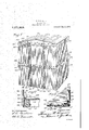
gis-Figure 1 a Vperspeceene end-of the body opta ycar tive; View,r
1 of ordinary ywood construction, with the "frosting sheets removed therefrom; Fig. 2 is t. an'enlarged detail, being substantially a seci tion taken on line22 `of Fig; Fig. is lan enlarged `detail;` being substantially a sectiontakenen lineB-' of Figl. l
Referring to the several figures of the f drawingsin which corresponding parts are `indicated by thesane `reference characters,"
lindicate's the end sill, 1l the side sill, `l2
p the beltraihl the side plate, 14 the end i i plate, `l5 the ridgepoldand 1G the .pnrlins of a car of ordinary wood construction. As
` he readily vlinderstood the frameworn RAILWAY-can.
`of the car comprising the parts name dis .- securely braced. in the ordinary manne'r so lasto provide a maximum of, rigiditybe-- tween the npper iframe comprising the-sideff.:` plates i3 and theend plates 14 andthe y lower frame comprising the side sills 11 and 18 being used in the usual manner for this. .i
be necessary to further describe it herein.
The ycar is provided on its sides with vertically-extending side sheathing 19 and at y.its ends with vertically-extending end sheathing 20. A deck 21 is provided by the use of laterally-extending flooring boards inasmuch as this construction iis 1* i well known in the art, it is not believed to y est` extending between the side sills 11 and suitably supported intermediately in any `appro-` priate manner. Grain-strips 22, of any suit- 4 able type, are used at the juncture between the side sheathing and the deck 21. Anend fascia 23 is provided covering the upper` `ends of the endl sheathing boards 20, i
Corning now to my improved strengtheni Ving means, 24 indicates a strip of 'pressed V steel extending in horizontal position across the end of the car opposite the belt rail 12,4 i'
f the ends of said .strip 2 4 being turned for f Ward along the sides of the car where theyv are secured in position by means of bolts 25.
26-27 indicate strengthening tormed of pressed stoel extending across-the `-end of the cur in vertical position opposite the end posts y18, the loivei-"ends of said strips strips 26--27 being secured to the end sill 10 i by means of bolts 28. At the points where the strips 26--27 extend across the horizon tally-extending strip 24, said 'strips 26-27 are offset outwardV so as to fit snugly against said strip and against the end of the car.v At their upper ends the strips 26-27 are also oset to tit snugly about the fasciaf23.' As shown clearly in Fig. l, eacho` the strips 2li-L27 is provided with a strengthening rib or corrugation 29 pressed therein longitudis nally thereof, said ribs 29 being fadedjat their upper ends into the offset portionsof the upper ends of the strips. Tlfie'` strip 24 is provided with strengthening ribs or corrugations SSO extending between the strips` .2G-27 and from said strips 264-27 ,toward the ends ofthe strip 24;. T e strips 265-27 are secured to the strip 24 and to t e end of the car by means of bolts 31 whic inthe so). end sills 10,-#corner posts 1'( and end posts 'r xrail 12 as shown in Fig. 3.
'ff 32 indicates a strengthening strip of pressed steel extending across the fascia 23, 'jhaving its ends turned forward along the sides of the car where it is secured in position by bolts 33 passing vthrough the side plates 13'. At the points Where the strip 32' extends across the upper ends of the strips 2(5*27 the strip 32 is offset to iit snugl,
about said ends and against the fascia 2g, bolts 34 being used for securing said strips to the end plate 14. The strip 32 has pressed therein longitudinally thereof a strengthening rib or corrugation 35 by which the strip is given the maximum longitudinal strength. vAs will be seen from an inspection of Fig. l, at the points Where the strips 26-27 are offset about the strip 24 and at the points where the strip 32 is offset about the strips 2G-27, the offset, in the construction showngd y 1s pressed in the bearing faces only of such" strips, leaving the outer edges of the strengthening ribs smooth and uniform.
By the Ause of a plurality of strengthening strips as shown provided with strengthening ribs pressed therein, With such strips firmly secured in place by pins or bolts passing through the end and side plates, the belt rail, and the side and end sills, respectively,
v a very strong construction is obtained capable of withstanding exceedingly heavy stresses Without undue Wear and tear upon the structure, the strengthening ribs being so disposed as to preventunder normal conditions of use anyundue bulging outward or other straining of the ends of the (car.
. Thatwhich I claim as my invention, and desire to secure by Letters Patent, is,-
1. In a device `for strengthen-ing the end of a car, the combination of a metal strip secured across the outer face of the car end and provided With a strengthening rib pressed in the strip longitudinally thereof, and a second metal strip secured across the outer face of the car end at an angle to said first-named strip and extending under the said first-named strip vand under the strengthening rib thereof, said second strip being provided with strengthening ribs pressed therein longitudinally of said strip at opposite sides of its point of contact .With said first-named strip.
. 2. In al device for strengthening the end` of a car, the combination of a metal strip secured across the outer-face of the car end' and provided with a strengthening rib pressed in the strip longitudinally thereof,
- and a second metal strip secured across the outer face of the car end at an angle to said first-named strip and extending under thesaid ,first-named. strip and under the strengthening rib thereof, said second strip being provided with strengthening ribs pressed therein longitudinally of said opposite sides of its point of contact with said first-named strip,.and saidfirst-namedstrip having an offset pressed in the bearing face thereof to fit snugly over said second strip.
3. In a device for strengtheningv the end of a car, the combination of a metal strip' secured in a horizontal positlon across the end of the car, and another metal strip secured in Vertical position across the outer face of the car end and across said horizontally-extending strip, said second-named strip being provided with a vertically-extending strengthening rib pressed therein, and said iirstr-named stripv being provided with horizontally-extending strengthening ribs pressed therein at opposite sides of said second-named strip, and means for securing said strips together at their crossing point independently of the said ribs.
l. In a device for strengthening the end of a car, the combination of a metal strip secured across the outer face of the car end, and a plurality of other metal strips each secured acrossthe outer face of the car end and the outer face of said first-named strip and each provided with a strengthening rib pressed therein longitudinally of the rstrip across said first-named strip, said firstnamed strip being provided with strengthening ribs pressed therein longitudinally'of the strip both between said second-named strips and also from\ said second-named strips'toward the ends of the first-named strip.
. 5. In a device for ,strengthening the end of a car, the combination of a metal strip secured in horizontal position across the end of the car, another metal strip secured in vertical position across the outer face ofthe car Ae'nd and across said horizontally-ex-' tending strip, and a third metal strip secured across the upper portion of said car endland across the upper end of said second1 named stripfsaid third-named strip being provided with a strengthening rib pressed therein exte dingfacross said second-named strip, said second-named strip being provided With `a strengthening rib pressed therein extending, across said first-named strip, and said Erst-named strip beingprovided with strengthening ribs pressed therein at opposite si'des of said second-named strip. y l
6. In a device for strengthening the end of a car, the combination'of a metal vstrip secured in horizontal position across the end of the car and having its ends turned and extended forward along the sides of the car opposite the belt rail, another metal strip secured in vertical position acr'ossnthe outer face of the car end and across said horizontally-extending strip, a third meta-l strip secured across the upper portion of said car y' \end and 'across the upper end of said secondn its ends turned `and extending forward Q along the sides opposite the side plates ol' the ear, and means l'or securing;r said several metal strips together at the points where the) cross each other.'
7. In :i derive l'or strengthening the end JilE a ear, lln` combination olanletal strip se- ,cured in horinontal position across the end of the ear and havingr its ends turned and `extended forward along the sides ol'l the ear `opposite the belt rail, another metal strip aufA serured in vertical position across the outer l'aee ot the rar end and across said horizontall\"extendin r stri ra third metal stri i sen l a i cured across the uppertportion ot' said ear `end and across the upper end olf said secondnamed strip, said third-named strip having its `ends 'turned and extending `forward alongr the sides opposite the side plates of the ear, and means lor .securing said several metal strips together at the points where they cross eaeh other, eaeh ofsaid metal strips being provided with longitudinallyextendingr strengthening ribs pressed thererin for substantially its 'full length across the end ot' the ear except that at the point where one of said strips crosses under another strip the strengthening rib. of tne under. strip s faded out.
tu. In a device for strengthening the end ot' a ear, the combination of a. metal strip se-` eured in horizontal position across the end ot the ear and having its ends turned and extended forward along the sides of the car opposite the belt rail,'a1iother metal strip secured in vertical position across the outer `l'aee of the ear end and across said horizontally-extending strip, a third metal strip seeured across the upper portion of said car end and across the upper end of said secondnamed strip, said third-named strip having its ends turned and extending forward along the sides opposite the side plates of the ear;` means forseenring said several ,metal strips together .at the points where they eross eaeh other, means for securing the Vforwardly-esternling ends ot'. said first-named strip to the belt rail, and means for securing the forwardly-extending ends ofsaid third strip to the side plates of the ear.
Witnesses:
W. II. DEBUSK, W. A. FURNNER.
Priority Applications (1)
| Application Number | Priority Date | Filing Date | Title |
|---|---|---|---|
| US87543514A US1171663A (en) | 1914-12-04 | 1914-12-04 | Railway-car. |
Applications Claiming Priority (1)
| Application Number | Priority Date | Filing Date | Title |
|---|---|---|---|
| US87543514A US1171663A (en) | 1914-12-04 | 1914-12-04 | Railway-car. |
Publications (1)
| Publication Number | Publication Date |
|---|---|
| US1171663A true US1171663A (en) | 1916-02-15 |
Family
ID=3239673
Family Applications (1)
| Application Number | Title | Priority Date | Filing Date |
|---|---|---|---|
| US87543514A Expired - Lifetime US1171663A (en) | 1914-12-04 | 1914-12-04 | Railway-car. |
Country Status (1)
| Country | Link |
|---|---|
| US (1) | US1171663A (en) |
-
1914
- 1914-12-04 US US87543514A patent/US1171663A/en not_active Expired - Lifetime
Similar Documents
| Publication | Publication Date | Title |
|---|---|---|
| US831654A (en) | Side construction for cars. | |
| US1171663A (en) | Railway-car. | |
| US2217110A (en) | Railway car construction | |
| US1639264A (en) | Wall structure for railway cars | |
| USRE15193E (en) | murphy | |
| US1037049A (en) | Underframe for railway-cars. | |
| US1496872A (en) | Railway-car end wall | |
| US784665A (en) | Car-frame. | |
| US1773397A (en) | Metallic wall plate | |
| US1186493A (en) | Sheet-metal end structure for railway-cars. | |
| US1202746A (en) | Underframe for railway-cars. | |
| US1398644A (en) | Corrugated-sheet-metal car end | |
| US926416A (en) | Car-body. | |
| US1067784A (en) | Hopper-car. | |
| US1248792A (en) | Car end construction. | |
| US1398645A (en) | Vertically-reinforced sheet-metal car end | |
| US1555971A (en) | End structure for railway cars | |
| US1642571A (en) | Cak end | |
| US2602407A (en) | Hatch construction for railway car roofs | |
| US541415A (en) | baiee | |
| US1156259A (en) | Underframe-reinforcement. | |
| US847503A (en) | Car construction. | |
| US1082974A (en) | Car-roof. | |
| US842869A (en) | Car construction. | |
| US1673456A (en) | Corrugated wall plate |