US11712848B2 - Modifying a building space in an apparatus for powder bed additive manufacturing a three-dimensional object - Google Patents

Modifying a building space in an apparatus for powder bed additive manufacturing a three-dimensional object Download PDF

Info

Publication number
US11712848B2
US11712848B2 US16/585,442 US201916585442A US11712848B2 US 11712848 B2 US11712848 B2 US 11712848B2 US 201916585442 A US201916585442 A US 201916585442A US 11712848 B2 US11712848 B2 US 11712848B2
Authority
US
United States
Prior art keywords
build
feed
container
cover
piston
Prior art date
Legal status (The legal status is an assumption and is not a legal conclusion. Google has not performed a legal analysis and makes no representation as to the accuracy of the status listed.)
Active, expires
Application number
US16/585,442
Other versions
US20200101666A1 (en
Inventor
Ankit Saharan
Erling Richard LaSalle
Current Assignee (The listed assignees may be inaccurate. Google has not performed a legal analysis and makes no representation or warranty as to the accuracy of the list.)
EOS of North America Inc
Original Assignee
EOS of North America Inc
Priority date (The priority date is an assumption and is not a legal conclusion. Google has not performed a legal analysis and makes no representation as to the accuracy of the date listed.)
Filing date
Publication date
Application filed by EOS of North America Inc filed Critical EOS of North America Inc
Priority to US16/585,442 priority Critical patent/US11712848B2/en
Assigned to EOS OF NORTH AMERICA, INC. reassignment EOS OF NORTH AMERICA, INC. ASSIGNMENT OF ASSIGNORS INTEREST (SEE DOCUMENT FOR DETAILS). Assignors: LASALLE, ERLING RICHARD, SAHARAN, ANKIT, DR.
Publication of US20200101666A1 publication Critical patent/US20200101666A1/en
Application granted granted Critical
Publication of US11712848B2 publication Critical patent/US11712848B2/en
Active legal-status Critical Current
Adjusted expiration legal-status Critical

Links

Images

Classifications

    • BPERFORMING OPERATIONS; TRANSPORTING
    • B29WORKING OF PLASTICS; WORKING OF SUBSTANCES IN A PLASTIC STATE IN GENERAL
    • B29CSHAPING OR JOINING OF PLASTICS; SHAPING OF MATERIAL IN A PLASTIC STATE, NOT OTHERWISE PROVIDED FOR; AFTER-TREATMENT OF THE SHAPED PRODUCTS, e.g. REPAIRING
    • B29C64/00Additive manufacturing, i.e. manufacturing of three-dimensional [3D] objects by additive deposition, additive agglomeration or additive layering, e.g. by 3D printing, stereolithography or selective laser sintering
    • B29C64/20Apparatus for additive manufacturing; Details thereof or accessories therefor
    • B29C64/245Platforms or substrates
    • BPERFORMING OPERATIONS; TRANSPORTING
    • B29WORKING OF PLASTICS; WORKING OF SUBSTANCES IN A PLASTIC STATE IN GENERAL
    • B29CSHAPING OR JOINING OF PLASTICS; SHAPING OF MATERIAL IN A PLASTIC STATE, NOT OTHERWISE PROVIDED FOR; AFTER-TREATMENT OF THE SHAPED PRODUCTS, e.g. REPAIRING
    • B29C64/00Additive manufacturing, i.e. manufacturing of three-dimensional [3D] objects by additive deposition, additive agglomeration or additive layering, e.g. by 3D printing, stereolithography or selective laser sintering
    • B29C64/20Apparatus for additive manufacturing; Details thereof or accessories therefor
    • B29C64/205Means for applying layers
    • BPERFORMING OPERATIONS; TRANSPORTING
    • B29WORKING OF PLASTICS; WORKING OF SUBSTANCES IN A PLASTIC STATE IN GENERAL
    • B29CSHAPING OR JOINING OF PLASTICS; SHAPING OF MATERIAL IN A PLASTIC STATE, NOT OTHERWISE PROVIDED FOR; AFTER-TREATMENT OF THE SHAPED PRODUCTS, e.g. REPAIRING
    • B29C64/00Additive manufacturing, i.e. manufacturing of three-dimensional [3D] objects by additive deposition, additive agglomeration or additive layering, e.g. by 3D printing, stereolithography or selective laser sintering
    • B29C64/20Apparatus for additive manufacturing; Details thereof or accessories therefor
    • B29C64/227Driving means
    • B29C64/232Driving means for motion along the axis orthogonal to the plane of a layer
    • BPERFORMING OPERATIONS; TRANSPORTING
    • B29WORKING OF PLASTICS; WORKING OF SUBSTANCES IN A PLASTIC STATE IN GENERAL
    • B29CSHAPING OR JOINING OF PLASTICS; SHAPING OF MATERIAL IN A PLASTIC STATE, NOT OTHERWISE PROVIDED FOR; AFTER-TREATMENT OF THE SHAPED PRODUCTS, e.g. REPAIRING
    • B29C64/00Additive manufacturing, i.e. manufacturing of three-dimensional [3D] objects by additive deposition, additive agglomeration or additive layering, e.g. by 3D printing, stereolithography or selective laser sintering
    • B29C64/20Apparatus for additive manufacturing; Details thereof or accessories therefor
    • B29C64/25Housings, e.g. machine housings
    • BPERFORMING OPERATIONS; TRANSPORTING
    • B29WORKING OF PLASTICS; WORKING OF SUBSTANCES IN A PLASTIC STATE IN GENERAL
    • B29CSHAPING OR JOINING OF PLASTICS; SHAPING OF MATERIAL IN A PLASTIC STATE, NOT OTHERWISE PROVIDED FOR; AFTER-TREATMENT OF THE SHAPED PRODUCTS, e.g. REPAIRING
    • B29C64/00Additive manufacturing, i.e. manufacturing of three-dimensional [3D] objects by additive deposition, additive agglomeration or additive layering, e.g. by 3D printing, stereolithography or selective laser sintering
    • B29C64/20Apparatus for additive manufacturing; Details thereof or accessories therefor
    • B29C64/255Enclosures for the building material, e.g. powder containers
    • BPERFORMING OPERATIONS; TRANSPORTING
    • B29WORKING OF PLASTICS; WORKING OF SUBSTANCES IN A PLASTIC STATE IN GENERAL
    • B29CSHAPING OR JOINING OF PLASTICS; SHAPING OF MATERIAL IN A PLASTIC STATE, NOT OTHERWISE PROVIDED FOR; AFTER-TREATMENT OF THE SHAPED PRODUCTS, e.g. REPAIRING
    • B29C64/00Additive manufacturing, i.e. manufacturing of three-dimensional [3D] objects by additive deposition, additive agglomeration or additive layering, e.g. by 3D printing, stereolithography or selective laser sintering
    • B29C64/30Auxiliary operations or equipment
    • B29C64/307Handling of material to be used in additive manufacturing
    • B29C64/321Feeding
    • BPERFORMING OPERATIONS; TRANSPORTING
    • B33ADDITIVE MANUFACTURING TECHNOLOGY
    • B33YADDITIVE MANUFACTURING, i.e. MANUFACTURING OF THREE-DIMENSIONAL [3-D] OBJECTS BY ADDITIVE DEPOSITION, ADDITIVE AGGLOMERATION OR ADDITIVE LAYERING, e.g. BY 3-D PRINTING, STEREOLITHOGRAPHY OR SELECTIVE LASER SINTERING
    • B33Y10/00Processes of additive manufacturing
    • BPERFORMING OPERATIONS; TRANSPORTING
    • B29WORKING OF PLASTICS; WORKING OF SUBSTANCES IN A PLASTIC STATE IN GENERAL
    • B29CSHAPING OR JOINING OF PLASTICS; SHAPING OF MATERIAL IN A PLASTIC STATE, NOT OTHERWISE PROVIDED FOR; AFTER-TREATMENT OF THE SHAPED PRODUCTS, e.g. REPAIRING
    • B29C64/00Additive manufacturing, i.e. manufacturing of three-dimensional [3D] objects by additive deposition, additive agglomeration or additive layering, e.g. by 3D printing, stereolithography or selective laser sintering
    • B29C64/10Processes of additive manufacturing
    • B29C64/141Processes of additive manufacturing using only solid materials
    • B29C64/153Processes of additive manufacturing using only solid materials using layers of powder being selectively joined, e.g. by selective laser sintering or melting
    • BPERFORMING OPERATIONS; TRANSPORTING
    • B33ADDITIVE MANUFACTURING TECHNOLOGY
    • B33YADDITIVE MANUFACTURING, i.e. MANUFACTURING OF THREE-DIMENSIONAL [3-D] OBJECTS BY ADDITIVE DEPOSITION, ADDITIVE AGGLOMERATION OR ADDITIVE LAYERING, e.g. BY 3-D PRINTING, STEREOLITHOGRAPHY OR SELECTIVE LASER SINTERING
    • B33Y30/00Apparatus for additive manufacturing; Details thereof or accessories therefor
    • BPERFORMING OPERATIONS; TRANSPORTING
    • B33ADDITIVE MANUFACTURING TECHNOLOGY
    • B33YADDITIVE MANUFACTURING, i.e. MANUFACTURING OF THREE-DIMENSIONAL [3-D] OBJECTS BY ADDITIVE DEPOSITION, ADDITIVE AGGLOMERATION OR ADDITIVE LAYERING, e.g. BY 3-D PRINTING, STEREOLITHOGRAPHY OR SELECTIVE LASER SINTERING
    • B33Y40/00Auxiliary operations or equipment, e.g. for material handling
    • YGENERAL TAGGING OF NEW TECHNOLOGICAL DEVELOPMENTS; GENERAL TAGGING OF CROSS-SECTIONAL TECHNOLOGIES SPANNING OVER SEVERAL SECTIONS OF THE IPC; TECHNICAL SUBJECTS COVERED BY FORMER USPC CROSS-REFERENCE ART COLLECTIONS [XRACs] AND DIGESTS
    • Y02TECHNOLOGIES OR APPLICATIONS FOR MITIGATION OR ADAPTATION AGAINST CLIMATE CHANGE
    • Y02PCLIMATE CHANGE MITIGATION TECHNOLOGIES IN THE PRODUCTION OR PROCESSING OF GOODS
    • Y02P10/00Technologies related to metal processing
    • Y02P10/25Process efficiency

Definitions

  • the invention relates to additive manufacture where an object is built up in layerwise fashion using a powder or similar fluent material, and more particularly to quickly modifying a building space of an apparatus for manufacturing three-dimensional objects by layerwise solidification of a powdery building material at locations corresponding to the object in the respective layers, so that a smaller area of the building space can be effectively and efficiently utilized in a build operation.
  • Machines for manufacturing three-dimensional objects by layerwise solidification of a powdery building material may have a building area size of 250 ⁇ 250 mm, the EOSINT M270 being one example. Due to the size of this building space, such devices may be larger than necessary for manufacturing small objects, which do not require such a large build area. A larger than necessary amount of a powdery material may therefore be used for making smaller objects, wasting much of the powdery material. The economic efficiency of the machine is thereby reduced when manufacturing smaller objects.
  • the presently disclosed embodiments broadly comprises a device for modifying a build container and a related feed container of a powder bed fusion additive manufacture apparatus.
  • This device reduces the size and surface area of the pre-existing build container, and may also do so for the feed container.
  • a retrofit for the additive manufacture apparatus is particularly advantageous and accomplished by the invention. The area being actively used for building an object by layerwise manufacture is thereby reduced.
  • the “standard” or pre-existing additive manufacture apparatus has a build platform vertically movable in the build container and extending between sidewalls of the build container.
  • the unmodified build container has an open top defining the size and surface area of the build container, and a feed platform vertically movable in a feed container between sidewalls of the feed container, the feed container having an open top defining the size and surface of the feed container.
  • a build piston having a top presenting a build surface upon which an object is built and a bottom is provided.
  • the build surface thereby presented by the build piston has a horizontal area which is smaller than that of the build container surface area.
  • a build piston attachment mechanism releasably affixes the bottom of the build piston to the build platform.
  • a build cover is sized to fit over the top of the unmodified build container.
  • the build cover can have an aperture in which the top of the build piston is receivable, and a shaft depending from the aperture within which the build piston vertically moves.
  • the shaft has sidewalls which are sealingly and slideably engaged by the piston.
  • a build cover attachment mechanism releasably affixes the build cover in place on the build container.
  • the device may further include a feed piston having a top presenting a feed surface which is smaller than that of the surface of the feed container.
  • the feed piston is locatable on the feed platform.
  • a feed cover is sized to fit over the top of the feed container.
  • the feed cover can have an aperture in which the top of the feed piston is receivable, and a shaft depending from the aperture within which the feed piston vertically moves.
  • the shaft has sidewalls which are sealingly and slideably engaged by the feed piston.
  • a feed cover attachment mechanism which may be the same as that for the build piston, releasably affixes the feed cover in place on the build container.
  • the build container and the feed container each present a top edge surrounding the top of the respective container, the respective cover overlying and resting upon the top edge.
  • the cover attachment mechanism can include quick release clamps which engage with the container sidewalls.
  • FIG. 1 schematically illustrates a typical AM apparatus using a powder material as the build material
  • FIG. 2 is a perspective view of a standard build area modified by an embodiment of the invention
  • FIG. 3 is a view similar to that of FIG. 2 with two covers in place;
  • FIG. 4 is a slightly exploded perspective view of a device for modifying the build area
  • FIG. 5 is a perspective view similar to that of FIG. 4 of the assembled device for modifying the build area
  • FIG. 6 A is a somewhat schematic view showing modified build and feed areas at the start of the build process
  • FIG. 6 B is a schematic view of the arrangement of FIG. 6 a but in side elevation;
  • FIG. 7 A is a somewhat schematic view showing the modified build and feed areas at the conclusion of the build process
  • FIG. 7 B is a schematic view of the arrangement of FIG. 7 a but in side elevation;
  • FIG. 8 is a bottom plan view of a build platform slightly modified for attachment of a piston cylinder
  • FIG. 9 is a bottom plan view of a piston cylinder showing attachment holes
  • FIG. 10 is a top perspective view of a piston cylinder
  • FIG. 11 is a view like that of FIG. 10 with the build plate in place;
  • FIG. 12 shows an attachment clamp for a cover
  • FIG. 13 illustrates how the attachment clamp works
  • FIG. 1 shows a relatively “standard” type laser sintering apparatus as an example of an apparatus for layerwise manufacturing a three-dimensional object by means of a generative manufacturing method.
  • SLS selective laser sintering
  • the apparatus generally includes a frame 1 , which opens on the top and forms a building chamber, and which includes therein a support in the shape of a building platform 2 which is moveable in the vertical direction and supports the three-dimensional object 3 to be manufactured to define a building field.
  • the building platform 2 is adjusted in the vertical direction such that the layer of the object 3 , which is to be solidified, lies within a building plane 4 (shown extending between the lead lines 4 ).
  • an application device 5 e.g., a blade, roller, sweeper, spreader etc., is provided for applying a powdery building material over the surface of the build area, which can be solidified by electromagnetic radiation, e.g. a laser.
  • An irradiation system includes a laser 6 as a source of the electromagnetic radiation. Further components of the irradiation system are a deflection means 8 , e.g., a scanner, by which a laser beam 7 generated by the laser 6 is deflected to an injection window 9 from a process chamber 10 and focused to a predetermined point within the building plane 4 . Further, a control unit 11 is provided, by which the components of the device are controlled in a coordinated manner for performing the building process. The control unit 11 is operated amongst others in accordance with computer-aided design (“CAD”) data of the object to be manufactured. The additive manufacturing apparatus further includes a gas circulation and gas preparing system which is not shown. The foregoing components are typical, and well known in the art.
  • CAD computer-aided design
  • a powdery material is stored in the storage and metering container 12 , which is the powder supply for the build.
  • the material is moved upwardly and into position for transfer over the building field 4 by the application device 5 via a powder platform 14 .
  • the powder material is provided in a container or build supply which is adjacent the build area.
  • the spreader 5 then passes into the now-raised pile or supply of powder, to push it across the build surface 4 , thereby making a fresh layer of unsolidified powder ready for the next cross section to be made.
  • any powder and/or powder mixture suitable for the laser sintering method may be used.
  • Such powders include for example synthetic powders such as polyamide or polystyrene, Polyethyr ether ketone (“PEEK”), metal powders such as high quality steel powders or other metal powders which are adapted to the respective purpose, in particular alloys, as well as synthetic coated sand or ceramic powders.
  • the application device 5 is moved over the building field and applies a powder layer in a predetermined thickness.
  • the overflow of powder is deposited in an overflow container 13 .
  • the cross section of the object 3 in the respective layer is irradiated by the laser beam 7 , and the powder is solidified according to the cross section, fusing with the previous layer underneath.
  • FIG. 2 shows a view of a building area 4 of a standard powder bed fusion additive manufacturing apparatus of the foregoing type which has been retrofitted by an embodiment of the presently disclosed embodiments to modify the building space, including the powder feed 12 for the building space.
  • the modification can be a reduction in the active build area, with a concomitant reduction in the adjacent powder supply.
  • the term “retrofittable” can mean that the apparatus is operable without partitioning the regular building space, using a retrofit kit or assembly which is quickly emplaced on the existing equipment with little modification of the regular building space. The retrofit kit is therefore readily removable when the building space is to be returned to its original condition.
  • the advantage to the retrofittable nature of the device is the relatively quick manner in which the building space can be modified.
  • FIGS. 2 and 3 show a part piston element or cylinder 20 for the reduced build assembly which has been attached to the standard build plate or platform 2 (used in the normal build mode for the full build area). Adjacent is the complimentary feed powder piston element or cylinder 24 , which is likewise attached to the standard feed plate or platform 14 , or it can simply be located on the feed platform without any rigid affixation, as it will be positioned for use in the depending sleeve or shaft of the cover (described hereafter). These standard part and powder plates will function in the usual manner, except now each has its respective reduced-size piston thereon. Those pistons 20 , 24 are aligned in covers 28 , 30 which have apertures 52 , 54 (e.g., see FIGS.
  • the covers have depending shafts or sleeves 29 , 31 which are integral to the covers, extending downwardly from the apertures 50 , 52 .
  • the pistons fit within the respective shafts, with the seal 38 forming a slidable seal between the top plate 20 b , 24 b and the sidewall of the shafts 29 , 31 . This contains powder within a telescoping arrangement.
  • the part piston 20 has a cylindrical body portion 20 a and a build plate 20 b at the top thereof.
  • the feed piston 24 has a like cylindrical body portion 24 a with a feed plate 24 b at the top thereof (see FIG. 6 B ).
  • a seal 38 here made of felt, is provided around the build/feed plate, to seal against the inside wall of the respective cover 28 , 30 (see FIG. 10 ).
  • the felt seals against the sidewalls of the shafts 29 , 31 as a gasket.
  • the feed piston 24 is constructed in a similar manner.
  • the felt material is simply an example and any sealing material would be suitable.
  • An attachment of the part/feed plate to its respective cylinder is made using screws or bolts 40 , for instance (e.g., FIG. 11 ).
  • the pistons 20 , 24 can be made in advance of attachment to the machine.
  • FIGS. 8 and 9 show how the piston cylinders are attached to the standard build/feed plates.
  • the latter have been modified to have holes 44 , here countersunk, to receive M6 screws 46 or the like through the bottom. Those screws 46 fit into threaded holes 48 provided in the cylinder bottoms, thus attaching the pistons to the standard size build plate.
  • Two dowel pins can also be provided that go in dowel holes shown in FIGS. 8 & 9 . These dowel pins may be used to allow more precise location and calibration of parts.
  • the reduced area build piston 20 is placed in the fully raised position within the build chamber. This is the level point of the start of the build process.
  • the reduced area feed piston 24 is placed in the lowermost position for the build (see also FIG. 6 A ).
  • the covers are then put in place.
  • FIGS. 5 , 12 and 13 details the cover attachment process.
  • These covers 28 , 30 have fixture clamps, here MITEE-BITETM type clamps 60 , which operate with a cam action, illustrated in FIG. 13 .
  • This kind of clamp has a rotatable part that rotates upon a pin, screw or the like that anchors the clamp to a surface, and has an offset element that can then be brought into engagement with an adjacent recess, wall or other structure.
  • the clamps 60 are located in wells 61 formed in the covers. The clamps press flat against the side wall of the M290 when engaged.
  • the covers have a shoulder 64 which overlies the edge 66 of the standard build chamber, so that it can be simply placed thereon.
  • the shoulder 64 aligns the plate in the center of the side walls of the standard build chamber.
  • the clamps 60 are then rotated to cam the washer associated therewith and fix the cover onto the build chamber sidewalls, thus quickly and easily putting the covers in place.
  • the reduced feed assembly has the piston 24 offset relative to the center, bringing the feed closer to the reduced build area.
  • Feed powder is then added to fill the feed container portion (i.e., the inside of the shaft 31 associated with the feed piston, the latter being in the lowermost position for the start of the build) (see, for example, FIG. 6 A ).
  • the additive manufacturing process proceeds with the retrofitted reduced build area, of course with the programming modified to accommodate the changed dimension of the build and powder feed areas. This is illustrated in FIGS. 6 A, 6 B, 7 A and 7 B .
  • FIGS. 6 A and 6 B show the start of the build
  • FIGS. 7 A and 7 B show the end positions of the build.
  • the manufacturing process is performed in an analogous manner to the previously described manufacturing process of the unmodified build area.
  • the control unit 11 is of course programmed for the now-modified and smaller building area being actively used.

Abstract

A standard powder bed fusion additive manufacture apparatus is provided with a device to modify the building space, including the powder feed for the building space, yielding a reduction in the active build area, with a concomitant reduction in the adjacent powder supply. A retrofit kit or assembly which is quickly emplaced on the existing equipment with little modification of the regular building space is provided, and is therefore readily removable when the building space is to be returned to its original condition. One advantage is the relatively quick manner in which the building space can be modified. A reduced area build piston is slideably received in a shaft depending from a cover that is emplaceable on the unmodified build area. The build piston moves with the pre-existing build platform. A like arrangement is provided for the feed container.

Description

FIELD OF THE INVENTION
The invention relates to additive manufacture where an object is built up in layerwise fashion using a powder or similar fluent material, and more particularly to quickly modifying a building space of an apparatus for manufacturing three-dimensional objects by layerwise solidification of a powdery building material at locations corresponding to the object in the respective layers, so that a smaller area of the building space can be effectively and efficiently utilized in a build operation.
BACKGROUND
Machines for manufacturing three-dimensional objects by layerwise solidification of a powdery building material, for example in a laser sintering machine, may have a building area size of 250×250 mm, the EOSINT M270 being one example. Due to the size of this building space, such devices may be larger than necessary for manufacturing small objects, which do not require such a large build area. A larger than necessary amount of a powdery material may therefore be used for making smaller objects, wasting much of the powdery material. The economic efficiency of the machine is thereby reduced when manufacturing smaller objects.
SUMMARY OF THE DISCLOSURE
It is an object of the present invention to provide an apparatus for reducing the active building area of a machine having a larger standard build area, and concomitantly reducing the powder feed area, and to do so with a retrofit that can be quickly put in place and removed so as to return the machine back to the standard build area.
For example, the presently disclosed embodiments broadly comprises a device for modifying a build container and a related feed container of a powder bed fusion additive manufacture apparatus. This device reduces the size and surface area of the pre-existing build container, and may also do so for the feed container. A retrofit for the additive manufacture apparatus is particularly advantageous and accomplished by the invention. The area being actively used for building an object by layerwise manufacture is thereby reduced.
The “standard” or pre-existing additive manufacture apparatus has a build platform vertically movable in the build container and extending between sidewalls of the build container. The unmodified build container has an open top defining the size and surface area of the build container, and a feed platform vertically movable in a feed container between sidewalls of the feed container, the feed container having an open top defining the size and surface of the feed container. In one form of the present invention, a build piston having a top presenting a build surface upon which an object is built and a bottom is provided. The build surface thereby presented by the build piston has a horizontal area which is smaller than that of the build container surface area. A build piston attachment mechanism releasably affixes the bottom of the build piston to the build platform.
A build cover is sized to fit over the top of the unmodified build container. The build cover can have an aperture in which the top of the build piston is receivable, and a shaft depending from the aperture within which the build piston vertically moves. The shaft has sidewalls which are sealingly and slideably engaged by the piston. A build cover attachment mechanism releasably affixes the build cover in place on the build container.
The device may further include a feed piston having a top presenting a feed surface which is smaller than that of the surface of the feed container. The feed piston is locatable on the feed platform. A feed cover is sized to fit over the top of the feed container. The feed cover can have an aperture in which the top of the feed piston is receivable, and a shaft depending from the aperture within which the feed piston vertically moves. The shaft has sidewalls which are sealingly and slideably engaged by the feed piston. A feed cover attachment mechanism, which may be the same as that for the build piston, releasably affixes the feed cover in place on the build container.
In a preferred form of the invention, the build container and the feed container each present a top edge surrounding the top of the respective container, the respective cover overlying and resting upon the top edge. Further, the cover attachment mechanism can include quick release clamps which engage with the container sidewalls.
The above advantages and other advantages and objects of the present disclosure will be made further apparent and understood upon consideration of the following exemplary description, taken in conjunction with the drawings, in which:
BRIEF DESCRIPTION OF THE DRAWINGS
FIG. 1 schematically illustrates a typical AM apparatus using a powder material as the build material;
FIG. 2 is a perspective view of a standard build area modified by an embodiment of the invention;
FIG. 3 is a view similar to that of FIG. 2 with two covers in place;
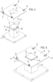
FIG. 4 is a slightly exploded perspective view of a device for modifying the build area;
FIG. 5 is a perspective view similar to that of FIG. 4 of the assembled device for modifying the build area;
FIG. 6A is a somewhat schematic view showing modified build and feed areas at the start of the build process;
FIG. 6B is a schematic view of the arrangement of FIG. 6 a but in side elevation;
FIG. 7A is a somewhat schematic view showing the modified build and feed areas at the conclusion of the build process;
FIG. 7B is a schematic view of the arrangement of FIG. 7 a but in side elevation;
FIG. 8 is a bottom plan view of a build platform slightly modified for attachment of a piston cylinder;
FIG. 9 is a bottom plan view of a piston cylinder showing attachment holes;
FIG. 10 is a top perspective view of a piston cylinder;
FIG. 11 is a view like that of FIG. 10 with the build plate in place;
FIG. 12 shows an attachment clamp for a cover;
FIG. 13 illustrates how the attachment clamp works;
DETAILED DESCRIPTION OF AN EMBODIMENT OF THE INVENTION
While this invention is susceptible of embodiments in many different forms, there is shown in the drawings, and will herein be described in detail, a preferred embodiment of the invention with the understanding that the present disclosure is to be considered as an exemplification of the principles of the invention and is not intended to limit the broad aspect of the invention to embodiments illustrated. As used herein, the term “the invention” is not intended to limit the scope of the claimed invention and is instead a term used to discuss exemplary embodiments of the invention for explanatory purposes only.
FIG. 1 shows a relatively “standard” type laser sintering apparatus as an example of an apparatus for layerwise manufacturing a three-dimensional object by means of a generative manufacturing method. It is understood that other terminology for describing this kind of additive manufacture is powder bed fusion, and selective laser sintering (“SLS”), where a powder (or similar fluent material) is spread over a build surface of a build area in the apparatus, and cross sections of an object (previously determined and reduced to a build file) are then fused, melted, and sintered one on top of the other to thereby unite to the previous layer and thereby generate the object (the build). The apparatus generally includes a frame 1, which opens on the top and forms a building chamber, and which includes therein a support in the shape of a building platform 2 which is moveable in the vertical direction and supports the three-dimensional object 3 to be manufactured to define a building field. The building platform 2 is adjusted in the vertical direction such that the layer of the object 3, which is to be solidified, lies within a building plane 4 (shown extending between the lead lines 4). Further, an application device 5 e.g., a blade, roller, sweeper, spreader etc., is provided for applying a powdery building material over the surface of the build area, which can be solidified by electromagnetic radiation, e.g. a laser.
An irradiation system includes a laser 6 as a source of the electromagnetic radiation. Further components of the irradiation system are a deflection means 8, e.g., a scanner, by which a laser beam 7 generated by the laser 6 is deflected to an injection window 9 from a process chamber 10 and focused to a predetermined point within the building plane 4. Further, a control unit 11 is provided, by which the components of the device are controlled in a coordinated manner for performing the building process. The control unit 11 is operated amongst others in accordance with computer-aided design (“CAD”) data of the object to be manufactured. The additive manufacturing apparatus further includes a gas circulation and gas preparing system which is not shown. The foregoing components are typical, and well known in the art.
A powdery material is stored in the storage and metering container 12, which is the powder supply for the build. The material is moved upwardly and into position for transfer over the building field 4 by the application device 5 via a powder platform 14. In the illustrated embodiment, the powder material is provided in a container or build supply which is adjacent the build area. As the build platform 2 is gradually moved downwardly in the build process, the powder material in the powder supply container is moved upwardly by the powder platform 14. The spreader 5 then passes into the now-raised pile or supply of powder, to push it across the build surface 4, thereby making a fresh layer of unsolidified powder ready for the next cross section to be made.
Regarding the powdery material, any powder and/or powder mixture suitable for the laser sintering method may be used. Such powders include for example synthetic powders such as polyamide or polystyrene, Polyethyr ether ketone (“PEEK”), metal powders such as high quality steel powders or other metal powders which are adapted to the respective purpose, in particular alloys, as well as synthetic coated sand or ceramic powders.
During operation of the laser sintering device, the application device 5 is moved over the building field and applies a powder layer in a predetermined thickness. The overflow of powder is deposited in an overflow container 13. Thereafter, the cross section of the object 3 in the respective layer is irradiated by the laser beam 7, and the powder is solidified according to the cross section, fusing with the previous layer underneath.
FIG. 2 shows a view of a building area 4 of a standard powder bed fusion additive manufacturing apparatus of the foregoing type which has been retrofitted by an embodiment of the presently disclosed embodiments to modify the building space, including the powder feed 12 for the building space. Here, the modification can be a reduction in the active build area, with a concomitant reduction in the adjacent powder supply. In at least some embodiments, the term “retrofittable” can mean that the apparatus is operable without partitioning the regular building space, using a retrofit kit or assembly which is quickly emplaced on the existing equipment with little modification of the regular building space. The retrofit kit is therefore readily removable when the building space is to be returned to its original condition. In some embodiments the advantage to the retrofittable nature of the device is the relatively quick manner in which the building space can be modified.
FIGS. 2 and 3 show a part piston element or cylinder 20 for the reduced build assembly which has been attached to the standard build plate or platform 2 (used in the normal build mode for the full build area). Adjacent is the complimentary feed powder piston element or cylinder 24, which is likewise attached to the standard feed plate or platform 14, or it can simply be located on the feed platform without any rigid affixation, as it will be positioned for use in the depending sleeve or shaft of the cover (described hereafter). These standard part and powder plates will function in the usual manner, except now each has its respective reduced-size piston thereon. Those pistons 20, 24 are aligned in covers 28, 30 which have apertures 52, 54 (e.g., see FIGS. 6 a and 6 b ) sized to the circumferential shape of the top of the respective piston. The covers have depending shafts or sleeves 29, 31 which are integral to the covers, extending downwardly from the apertures 50, 52. The pistons fit within the respective shafts, with the seal 38 forming a slidable seal between the top plate 20 b, 24 b and the sidewall of the shafts 29,31. This contains powder within a telescoping arrangement.
Looking at FIGS. 4 and 5 , the part piston 20 has a cylindrical body portion 20 a and a build plate 20 b at the top thereof. The feed piston 24 has a like cylindrical body portion 24 a with a feed plate 24 b at the top thereof (see FIG. 6B). A seal 38, here made of felt, is provided around the build/feed plate, to seal against the inside wall of the respective cover 28, 30 (see FIG. 10 ). The felt seals against the sidewalls of the shafts 29,31 as a gasket. It will be understood that the feed piston 24 is constructed in a similar manner. As further understood, the felt material is simply an example and any sealing material would be suitable. An attachment of the part/feed plate to its respective cylinder is made using screws or bolts 40, for instance (e.g., FIG. 11 ). The pistons 20, 24 can be made in advance of attachment to the machine.
FIGS. 8 and 9 show how the piston cylinders are attached to the standard build/feed plates. The latter have been modified to have holes 44, here countersunk, to receive M6 screws 46 or the like through the bottom. Those screws 46 fit into threaded holes 48 provided in the cylinder bottoms, thus attaching the pistons to the standard size build plate. Two dowel pins can also be provided that go in dowel holes shown in FIGS. 8 & 9 . These dowel pins may be used to allow more precise location and calibration of parts.
Turning to FIG. 3 for instance, the reduced area build piston 20 is placed in the fully raised position within the build chamber. This is the level point of the start of the build process. The reduced area feed piston 24 is placed in the lowermost position for the build (see also FIG. 6A). The covers are then put in place.
FIGS. 5, 12 and 13 details the cover attachment process. These covers 28, 30 have fixture clamps, here MITEE-BITE™ type clamps 60, which operate with a cam action, illustrated in FIG. 13 . This kind of clamp has a rotatable part that rotates upon a pin, screw or the like that anchors the clamp to a surface, and has an offset element that can then be brought into engagement with an adjacent recess, wall or other structure. The clamps 60 are located in wells 61 formed in the covers. The clamps press flat against the side wall of the M290 when engaged. The covers have a shoulder 64 which overlies the edge 66 of the standard build chamber, so that it can be simply placed thereon. The shoulder 64 aligns the plate in the center of the side walls of the standard build chamber. The clamps 60 are then rotated to cam the washer associated therewith and fix the cover onto the build chamber sidewalls, thus quickly and easily putting the covers in place. It will be noted that the reduced feed assembly has the piston 24 offset relative to the center, bringing the feed closer to the reduced build area.
Feed powder is then added to fill the feed container portion (i.e., the inside of the shaft 31 associated with the feed piston, the latter being in the lowermost position for the start of the build) (see, for example, FIG. 6A). The additive manufacturing process proceeds with the retrofitted reduced build area, of course with the programming modified to accommodate the changed dimension of the build and powder feed areas. This is illustrated in FIGS. 6A, 6B, 7A and 7B. FIGS. 6A and 6B show the start of the build, and FIGS. 7A and 7B show the end positions of the build.
The manufacturing process is performed in an analogous manner to the previously described manufacturing process of the unmodified build area. The control unit 11 is of course programmed for the now-modified and smaller building area being actively used.
Thus, while the invention has been described in relation to a particular embodiment, the matter set forth in the foregoing description and accompanying drawings is offered by way of illustration only and not as a limitation. While a particular embodiment has been shown and described, it will be apparent to those skilled in the art that changes and modifications may be made without departing from the broader aspects of the inventors' contribution. The actual scope of the protection sought is intended to be defined in claims as allowed, when viewed in their proper perspective based on the prior art.

Claims (10)

What is claimed is:
1. A device for modifying a build container of a powder bed fusion additive manufacture apparatus to reduce a size and surface area of the build container being actively used for building an object by layerwise manufacture, the additive manufacture apparatus having a build platform vertically movable in the build container and extending between sidewalls of the build container, the build container having an open top defining the size and surface area of the build container, the device comprising:
a build piston having a top presenting a build surface upon which the object is built and a bottom, the build surface having a horizontal area which is smaller than that of the build container surface area;
a build piston attachment mechanism releasably affixing the bottom of the build piston to the build platform;
a build cover sized to fit over the top of the build container, the build cover having an aperture in which the top of the build piston is receivable, and a shaft depending from the aperture within which the build piston vertically moves, the shaft having sidewalls which are sealingly and slideably engaged by the piston;
a build cover attachment mechanism releasably affixing the build cover in place on the build container,
wherein the build container presents a top edge surrounding the top of the build container, the cover overlying and resting upon the top edge, the build cover attachment mechanism comprising quick release clamps which engage with the build container sidewalls,
and further wherein the quick release clamps each comprise an element rotatably mounted on the cover so as to present a portion of the clamp accessible on a top of the cover which can be rotated to extend an element of the clamp outboard from the cover when rotated to contact one of the build container sidewalls upon rotation in a static fit to fix the cover removably in place.
2. The device of claim 1, wherein the build container sidewall includes a recess which receives the element of the quick release clamp therein to engage with the build container sidewall.
3. The device of claim 1, wherein the manufacture apparatus further includes:
a feed container for powder material used in building the object, and a feed platform vertically movable in the feed container and extending between sidewalls of the feed container, the feed container having an open top defining a size and surface of the feed container, the device for modifying further including a feed piston having a top presenting a feed surface which is smaller than that of the surface of the feed container, the feed piston being locatable on the feed platform;
a feed cover sized to fit over the top of the feed container, the feed cover having an aperture in which the top of the feed piston is receivable, and a shaft depending from the aperture within which the feed piston vertically moves, the shaft having sidewalls which are sealingly and slideably engaged by the feed piston; and
a feed cover attachment mechanism releasably affixing the feed cover in place on the build container.
4. The device of claim 3, wherein the feed container presents a top edge surrounding the top of the feed container, the cover overlying and resting upon the top edge, the feed cover attachment mechanism comprising quick release clamps which engage with the feed container sidewalls,
the build container sidewalls include recesses within which the element engages upon rotation to place part of the element within one of the recesses, the element engaging within the recess in a static fit to fix the cover removably in place.
5. The device of claim 1, wherein the build piston further includes a build plate which is attached to the top of the build piston, and the build plate thereby functioning as the build surface upon which the object is built.
6. The device of claim 3, wherein the feed piston further includes a feed plate which is attached to the top of the feed piston, and the feed plate thereby functioning as the feed surface upon which material to be used in the build process is carried.
7. A retrofit device for modifying a build container and a related feed container of a powder bed fusion additive manufacture apparatus to reduce a size and surface area of the build container and the feed container being actively used for building an object by layerwise manufacture, the additive manufacture apparatus having a build platform vertically movable in the build container and extending between sidewalls of the build container, the build container having an open top defining the size and surface area of the build container, and a feed platform vertically movable in the feed container between sidewalls of the feed container, the feed container having an open top defining a size and surface of the feed container, the retrofit device comprising:
a build piston having a top presenting a build surface upon which the object is built and a bottom, the build surface having a horizontal area which is smaller than that of the build container surface area;
a build piston attachment mechanism releasably affixing the bottom of the build piston to the build platform;
a build cover sized to fit over the top of the build container, the build cover having an aperture in which the top of the build piston is receivable, and a shaft depending from the aperture within which the build piston vertically moves, the shaft having sidewalls which are sealingly and slideably engaged by the piston;
a build cover attachment mechanism releasably affixing the build cover in place on the build container;
a feed piston having a top presenting a feed surface which is smaller than that of the surface of the feed container, the feed piston being locatable on the feed platform;
a feed cover sized to fit over the top of the feed container, the feed cover having an aperture in which the top of the feed piston is receivable, and a shaft depending from the aperture within which the feed piston vertically moves, the shaft having sidewalls which are sealingly and slideably engaged by the feed piston; and
a feed cover attachment mechanism releasably affixing the feed cover in place on the build container,
wherein the build container and the feed container each present a top edge surrounding the top of the respective container, the respective cover overlying and resting upon the top edge, the cover attachment mechanism comprising quick release clamps which engage with the container sidewalls,
the quick release clamps each present a portion of the clamp accessible on a top of the cover which can be rotated to extend an element of the clamp outboard from the cover when rotated, the element engaging with the sidewall in a static fit to fix the cover removably in place.
8. A device for modifying a build container of a powder bed fusion additive manufacture apparatus to reduce a size and surface area of the build container being actively used for building an object by layerwise manufacture, the additive manufacture apparatus having a build platform vertically movable in the build container and which extends between sidewalls of the build container, the build container having an open top defining the size and surface area of the build container, the device comprising:
a build piston having a top presenting a build surface upon which an object is built, and a build piston bottom, the build surface of the build piston having a horizontal area which is smaller than that of the build container surface area;
a build piston attachment mechanism releasably affixing the bottom of the build piston to the build platform;
a build cover sized to fit over the top of the build container, the build cover having an aperture in which the top of the build piston is receivable, and a shaft depending from the aperture within which the build piston vertically moves, the shaft having sidewalls which are sealingly and slideably engaged along sidewalls of the piston; and
at least one build cover attachment mechanism releasably affixing the build cover in place on the build container with the build piston received within the build cover shaft, whereby the surface area of the build container being actively used for building an object is reduced to an area of the build surface of the build piston,
wherein the build container presents a top edge shoulder surrounding the top of the build container, the cover overlying and resting upon the shoulder, the build cover attachment mechanism comprising quick release clamps on at least two opposite sides of the cover which engage with the container sidewalls, the quick release clamps each comprise a portion accessible on a top surface of the cover which is engaged in use to extend an element outboard from the cover when rotated, the container sidewalls having a part which an element engages upon rotation placing part of the element, the element engaging in a static fit to fix the cover removably in place.
9. The device of claim 8, wherein the quick release clamps each comprise an element rotatably mounted on the cover to extend outboard from the cover when rotated, the container sidewalls including recesses within which an element engages upon rotation to place part of the element within the recess, the element engaging within the recess in a static fit to fix the cover removably in place.
10. The device of claim 8, wherein the manufacture apparatus further includes:
a feed container for powder material used in building the object, and a feed platform vertically movable in the feed container and extending between sidewalls of the feed container, the feed container having an open top defining the size and surface of the feed container, the device for modifying further including a feed piston having a top presenting a feed surface which is smaller than that of a surface of the feed container, the feed piston being locatable on the feed platform; and
a feed cover sized to fit over the top of the feed container, the feed cover having a feed cover aperture in which the top of the feed piston is receivable, and a feed cover shaft depending from the feed cover aperture within which the feed piston vertically moves, the shaft having sidewalls which are sealingly and slideably engaged along sidewalls of the feed piston, and a feed cover attachment mechanism releasably affixing the feed cover in place on the build container, whereby the surface area of the feed container being actively used in building an object is reduced to an area of the feed piston top,
wherein the feed container presents a top edge shoulder surrounding the top of the feed container, the cover overlying and resting upon the feed container shoulder, the feed cover attachment mechanism comprising quick release clamps which engage with the feed container sidewalls, the quick release clamps each comprise a portion that is freely accessible on a surface of the cover which when engaged has an element that extends outboard from the feed cover when rotated, the element engaging with an adjacent sidewall in a static fit to fix the feed cover removably in place.
US16/585,442 2018-09-27 2019-09-27 Modifying a building space in an apparatus for powder bed additive manufacturing a three-dimensional object Active 2042-02-17 US11712848B2 (en)

Priority Applications (1)

Application Number Priority Date Filing Date Title
US16/585,442 US11712848B2 (en) 2018-09-27 2019-09-27 Modifying a building space in an apparatus for powder bed additive manufacturing a three-dimensional object

Applications Claiming Priority (2)

Application Number Priority Date Filing Date Title
US201862737548P 2018-09-27 2018-09-27
US16/585,442 US11712848B2 (en) 2018-09-27 2019-09-27 Modifying a building space in an apparatus for powder bed additive manufacturing a three-dimensional object

Publications (2)

Publication Number Publication Date
US20200101666A1 US20200101666A1 (en) 2020-04-02
US11712848B2 true US11712848B2 (en) 2023-08-01

Family

ID=69947092

Family Applications (1)

Application Number Title Priority Date Filing Date
US16/585,442 Active 2042-02-17 US11712848B2 (en) 2018-09-27 2019-09-27 Modifying a building space in an apparatus for powder bed additive manufacturing a three-dimensional object

Country Status (1)

Country Link
US (1) US11712848B2 (en)

Families Citing this family (2)

* Cited by examiner, † Cited by third party
Publication number Priority date Publication date Assignee Title
EP4169640A1 (en) * 2021-10-22 2023-04-26 Incus GmbH Apparatus, modular system and stereolithographic additive manufacturing method
JP7279234B1 (en) * 2022-04-27 2023-05-22 株式会社ソディック Additive manufacturing machines and small area manufacturing units for additive manufacturing machines

Citations (5)

* Cited by examiner, † Cited by third party
Publication number Priority date Publication date Assignee Title
US4695030A (en) * 1985-09-03 1987-09-22 Fischer Jay P Quick release clamp
US20060032838A1 (en) * 2004-08-10 2006-02-16 Muylaert Neal W Selective laser sintering reduced volume feed mechanism
US20070026099A1 (en) * 2005-07-26 2007-02-01 Aspect Inc. Powder sinter layered manufacturing apparatus
US20110252618A1 (en) * 2010-04-17 2011-10-20 Evonik Degussa Gmbh Apparatus for reducing the size of the lower construction chamber of a laser sintering installation
US20190126544A1 (en) * 2016-11-29 2019-05-02 Hewlett-Packard Development Company, L.P. Accessory for three-dimensional printing

Patent Citations (5)

* Cited by examiner, † Cited by third party
Publication number Priority date Publication date Assignee Title
US4695030A (en) * 1985-09-03 1987-09-22 Fischer Jay P Quick release clamp
US20060032838A1 (en) * 2004-08-10 2006-02-16 Muylaert Neal W Selective laser sintering reduced volume feed mechanism
US20070026099A1 (en) * 2005-07-26 2007-02-01 Aspect Inc. Powder sinter layered manufacturing apparatus
US20110252618A1 (en) * 2010-04-17 2011-10-20 Evonik Degussa Gmbh Apparatus for reducing the size of the lower construction chamber of a laser sintering installation
US20190126544A1 (en) * 2016-11-29 2019-05-02 Hewlett-Packard Development Company, L.P. Accessory for three-dimensional printing

Also Published As

Publication number Publication date
US20200101666A1 (en) 2020-04-02

Similar Documents

Publication Publication Date Title
US8845319B2 (en) Means for modifying a building space and device for manufacturing a three-dimensional object having means for modifying a building space
US11712848B2 (en) Modifying a building space in an apparatus for powder bed additive manufacturing a three-dimensional object
RU2631793C1 (en) Layering device for 3d printer
EP1925431B1 (en) Container for a device for layerwise manufacturing of a three dimensional object
US20200147885A1 (en) Supplying build material
US7153463B2 (en) Device for treating powder for a device which produces a three-dimensional object device for producing a three-dimensional object and method for the production thereof
US20060108712A1 (en) Device and method for producing a three-dimensional object by means of a generative production method
DE102006013489A1 (en) Apparatus and method for aligning a removable building chamber within a service chamber
JP6188108B1 (en) Coating apparatus construction, three-dimensional printer and method of applying two layers of particulate construction material
KR101676606B1 (en) Powder supply apparatus for Three-dimensional printer
RU2424904C2 (en) Device and method for layer-by-layer production of 3d object
EP1925434B1 (en) Apparatus for layered manufacture of three dimensional objects and method for calibrating its optical system
US20140348969A1 (en) Powder dispensing apparatus and method
CN107087400B (en) Machine and method for powder-based additive manufacturing
DE102006055052A1 (en) Apparatus for layering a three-dimensional object
US10780636B2 (en) Recoating unit, recoating method, device and method for additive manufacturing of a three-dimensional object
US20190091921A1 (en) Recoating Unit, Device and Method for Producing a Three-Dimensional Object
EP3263338A2 (en) Coating unit, coating method, method and device for generating a three-dimensional object
EP1963078A1 (en) Device and method for building up a three-dimensional object layer by layer
EP3693103A1 (en) Powder supply device and three-dimensional laminate modeling device
EP3349969A1 (en) Array of printhead modules for additive manufacturing system
EP1925430A1 (en) Apparatus for layered production of a three-dimensional object and method of fitting and withdrawing a container
DE102006055053A1 (en) Apparatus for layering a three-dimensional object
CN104057617A (en) Scraper system of laser sintering 3D (three-dimensional) printing machine
DE102006055054A1 (en) Apparatus for layering a three-dimensional object

Legal Events

Date Code Title Description
FEPP Fee payment procedure

Free format text: ENTITY STATUS SET TO UNDISCOUNTED (ORIGINAL EVENT CODE: BIG.); ENTITY STATUS OF PATENT OWNER: LARGE ENTITY

AS Assignment

Owner name: EOS OF NORTH AMERICA, INC., MICHIGAN

Free format text: ASSIGNMENT OF ASSIGNORS INTEREST;ASSIGNORS:SAHARAN, ANKIT, DR.;LASALLE, ERLING RICHARD;REEL/FRAME:050781/0965

Effective date: 20191003

STPP Information on status: patent application and granting procedure in general

Free format text: DOCKETED NEW CASE - READY FOR EXAMINATION

STPP Information on status: patent application and granting procedure in general

Free format text: NON FINAL ACTION MAILED

STPP Information on status: patent application and granting procedure in general

Free format text: PUBLICATIONS -- ISSUE FEE PAYMENT VERIFIED

STCF Information on status: patent grant

Free format text: PATENTED CASE