US11712648B2 - Water-treating ceramic filter module - Google Patents
Water-treating ceramic filter module Download PDFInfo
- Publication number
- US11712648B2 US11712648B2 US16/962,656 US201916962656A US11712648B2 US 11712648 B2 US11712648 B2 US 11712648B2 US 201916962656 A US201916962656 A US 201916962656A US 11712648 B2 US11712648 B2 US 11712648B2
- Authority
- US
- United States
- Prior art keywords
- water
- flow paths
- filter module
- ceramic filter
- treating ceramic
- Prior art date
- Legal status (The legal status is an assumption and is not a legal conclusion. Google has not performed a legal analysis and makes no representation as to the accuracy of the status listed.)
- Active, expires
Links
- 239000000919 ceramic Substances 0.000 title claims abstract description 108
- XLYOFNOQVPJJNP-UHFFFAOYSA-N water Substances O XLYOFNOQVPJJNP-UHFFFAOYSA-N 0.000 claims abstract description 104
- 210000002421 cell wall Anatomy 0.000 claims abstract description 41
- 230000000149 penetrating effect Effects 0.000 claims abstract description 24
- 238000007599 discharging Methods 0.000 claims abstract description 5
- 238000004891 communication Methods 0.000 claims abstract description 4
- 239000000463 material Substances 0.000 claims description 25
- 239000013013 elastic material Substances 0.000 claims description 10
- 229920002379 silicone rubber Polymers 0.000 claims description 8
- 239000004945 silicone rubber Substances 0.000 claims description 8
- 229920000459 Nitrile rubber Polymers 0.000 claims description 7
- 229920002943 EPDM rubber Polymers 0.000 claims description 6
- 229920001973 fluoroelastomer Polymers 0.000 claims description 6
- 239000012670 alkaline solution Substances 0.000 claims description 3
- 239000012528 membrane Substances 0.000 description 30
- 238000001223 reverse osmosis Methods 0.000 description 29
- 238000001179 sorption measurement Methods 0.000 description 23
- 239000011368 organic material Substances 0.000 description 19
- 239000002245 particle Substances 0.000 description 19
- 239000011148 porous material Substances 0.000 description 18
- VYPSYNLAJGMNEJ-UHFFFAOYSA-N Silicium dioxide Chemical compound O=[Si]=O VYPSYNLAJGMNEJ-UHFFFAOYSA-N 0.000 description 10
- 230000000052 comparative effect Effects 0.000 description 10
- -1 SUS304 Chemical class 0.000 description 9
- 238000011001 backwashing Methods 0.000 description 9
- 239000000356 contaminant Substances 0.000 description 9
- 230000002093 peripheral effect Effects 0.000 description 8
- 238000007789 sealing Methods 0.000 description 7
- PNEYBMLMFCGWSK-UHFFFAOYSA-N aluminium oxide Inorganic materials [O-2].[O-2].[O-2].[Al+3].[Al+3] PNEYBMLMFCGWSK-UHFFFAOYSA-N 0.000 description 6
- 229910052878 cordierite Inorganic materials 0.000 description 5
- JSKIRARMQDRGJZ-UHFFFAOYSA-N dimagnesium dioxido-bis[(1-oxido-3-oxo-2,4,6,8,9-pentaoxa-1,3-disila-5,7-dialuminabicyclo[3.3.1]nonan-7-yl)oxy]silane Chemical compound [Mg++].[Mg++].[O-][Si]([O-])(O[Al]1O[Al]2O[Si](=O)O[Si]([O-])(O1)O2)O[Al]1O[Al]2O[Si](=O)O[Si]([O-])(O1)O2 JSKIRARMQDRGJZ-UHFFFAOYSA-N 0.000 description 5
- 238000004519 manufacturing process Methods 0.000 description 5
- 238000011144 upstream manufacturing Methods 0.000 description 5
- CPLXHLVBOLITMK-UHFFFAOYSA-N Magnesium oxide Chemical compound [Mg]=O CPLXHLVBOLITMK-UHFFFAOYSA-N 0.000 description 4
- 239000004698 Polyethylene Substances 0.000 description 4
- 229910052751 metal Inorganic materials 0.000 description 4
- 239000002184 metal Substances 0.000 description 4
- 150000002739 metals Chemical class 0.000 description 4
- 229920000573 polyethylene Polymers 0.000 description 4
- 239000011248 coating agent Substances 0.000 description 3
- 238000000576 coating method Methods 0.000 description 3
- 239000008119 colloidal silica Substances 0.000 description 3
- 238000001914 filtration Methods 0.000 description 3
- 229910044991 metal oxide Inorganic materials 0.000 description 3
- 150000004706 metal oxides Chemical class 0.000 description 3
- 239000000843 powder Substances 0.000 description 3
- 238000000746 purification Methods 0.000 description 3
- 229920005989 resin Polymers 0.000 description 3
- 239000011347 resin Substances 0.000 description 3
- 238000000926 separation method Methods 0.000 description 3
- 230000035939 shock Effects 0.000 description 3
- 239000000377 silicon dioxide Substances 0.000 description 3
- GWEVSGVZZGPLCZ-UHFFFAOYSA-N Titan oxide Chemical compound O=[Ti]=O GWEVSGVZZGPLCZ-UHFFFAOYSA-N 0.000 description 2
- XLOMVQKBTHCTTD-UHFFFAOYSA-N Zinc monoxide Chemical compound [Zn]=O XLOMVQKBTHCTTD-UHFFFAOYSA-N 0.000 description 2
- 210000004027 cell Anatomy 0.000 description 2
- 238000004140 cleaning Methods 0.000 description 2
- 238000005260 corrosion Methods 0.000 description 2
- 230000007797 corrosion Effects 0.000 description 2
- 238000010586 diagram Methods 0.000 description 2
- 238000009826 distribution Methods 0.000 description 2
- 230000000694 effects Effects 0.000 description 2
- 230000001747 exhibiting effect Effects 0.000 description 2
- 239000007788 liquid Substances 0.000 description 2
- 239000000395 magnesium oxide Substances 0.000 description 2
- 239000013535 sea water Substances 0.000 description 2
- 239000002002 slurry Substances 0.000 description 2
- 238000012360 testing method Methods 0.000 description 2
- 239000005995 Aluminium silicate Substances 0.000 description 1
- 241000531908 Aramides Species 0.000 description 1
- QPLDLSVMHZLSFG-UHFFFAOYSA-N Copper oxide Chemical compound [Cu]=O QPLDLSVMHZLSFG-UHFFFAOYSA-N 0.000 description 1
- 239000005751 Copper oxide Substances 0.000 description 1
- 239000004952 Polyamide Substances 0.000 description 1
- 239000004743 Polypropylene Substances 0.000 description 1
- 239000004793 Polystyrene Substances 0.000 description 1
- 229910001069 Ti alloy Inorganic materials 0.000 description 1
- 239000011358 absorbing material Substances 0.000 description 1
- 238000009825 accumulation Methods 0.000 description 1
- WNROFYMDJYEPJX-UHFFFAOYSA-K aluminium hydroxide Chemical compound [OH-].[OH-].[OH-].[Al+3] WNROFYMDJYEPJX-UHFFFAOYSA-K 0.000 description 1
- 235000012211 aluminium silicate Nutrition 0.000 description 1
- 239000004760 aramid Substances 0.000 description 1
- 229920003235 aromatic polyamide Polymers 0.000 description 1
- 229920002678 cellulose Polymers 0.000 description 1
- 235000010980 cellulose Nutrition 0.000 description 1
- 229910010293 ceramic material Inorganic materials 0.000 description 1
- 239000000701 coagulant Substances 0.000 description 1
- 229910052681 coesite Inorganic materials 0.000 description 1
- 238000011109 contamination Methods 0.000 description 1
- 229910000431 copper oxide Inorganic materials 0.000 description 1
- 229910052593 corundum Inorganic materials 0.000 description 1
- 229910052906 cristobalite Inorganic materials 0.000 description 1
- 230000001186 cumulative effect Effects 0.000 description 1
- 238000000354 decomposition reaction Methods 0.000 description 1
- 238000010612 desalination reaction Methods 0.000 description 1
- 230000002542 deteriorative effect Effects 0.000 description 1
- 238000011161 development Methods 0.000 description 1
- 230000018109 developmental process Effects 0.000 description 1
- 239000003657 drainage water Substances 0.000 description 1
- 238000011049 filling Methods 0.000 description 1
- 230000005484 gravity Effects 0.000 description 1
- 239000001866 hydroxypropyl methyl cellulose Substances 0.000 description 1
- 235000010979 hydroxypropyl methyl cellulose Nutrition 0.000 description 1
- 229920003088 hydroxypropyl methyl cellulose Polymers 0.000 description 1
- UFVKGYZPFZQRLF-UHFFFAOYSA-N hydroxypropyl methyl cellulose Chemical compound OC1C(O)C(OC)OC(CO)C1OC1C(O)C(O)C(OC2C(C(O)C(OC3C(C(O)C(O)C(CO)O3)O)C(CO)O2)O)C(CO)O1 UFVKGYZPFZQRLF-UHFFFAOYSA-N 0.000 description 1
- NLYAJNPCOHFWQQ-UHFFFAOYSA-N kaolin Chemical compound O.O.O=[Al]O[Si](=O)O[Si](=O)O[Al]=O NLYAJNPCOHFWQQ-UHFFFAOYSA-N 0.000 description 1
- 238000012423 maintenance Methods 0.000 description 1
- QSHDDOUJBYECFT-UHFFFAOYSA-N mercury Chemical compound [Hg] QSHDDOUJBYECFT-UHFFFAOYSA-N 0.000 description 1
- 229910052753 mercury Inorganic materials 0.000 description 1
- 238000000034 method Methods 0.000 description 1
- 229920000609 methyl cellulose Polymers 0.000 description 1
- 239000001923 methylcellulose Substances 0.000 description 1
- 235000010981 methylcellulose Nutrition 0.000 description 1
- 239000003094 microcapsule Substances 0.000 description 1
- 239000000203 mixture Substances 0.000 description 1
- 238000000465 moulding Methods 0.000 description 1
- 229920001778 nylon Polymers 0.000 description 1
- 230000000737 periodic effect Effects 0.000 description 1
- 229920002647 polyamide Polymers 0.000 description 1
- 229920000139 polyethylene terephthalate Polymers 0.000 description 1
- 239000005020 polyethylene terephthalate Substances 0.000 description 1
- 239000002861 polymer material Substances 0.000 description 1
- 229920001155 polypropylene Polymers 0.000 description 1
- 229920002223 polystyrene Polymers 0.000 description 1
- 239000004800 polyvinyl chloride Substances 0.000 description 1
- 230000002028 premature Effects 0.000 description 1
- 238000011084 recovery Methods 0.000 description 1
- 230000008929 regeneration Effects 0.000 description 1
- 238000011069 regeneration method Methods 0.000 description 1
- 238000011160 research Methods 0.000 description 1
- 150000003839 salts Chemical class 0.000 description 1
- 239000004576 sand Substances 0.000 description 1
- 238000004062 sedimentation Methods 0.000 description 1
- 239000004065 semiconductor Substances 0.000 description 1
- 239000010865 sewage Substances 0.000 description 1
- 238000005245 sintering Methods 0.000 description 1
- 238000000638 solvent extraction Methods 0.000 description 1
- 125000006850 spacer group Chemical group 0.000 description 1
- 239000010935 stainless steel Substances 0.000 description 1
- 229910001220 stainless steel Inorganic materials 0.000 description 1
- 229910052682 stishovite Inorganic materials 0.000 description 1
- 239000000126 substance Substances 0.000 description 1
- 230000003746 surface roughness Effects 0.000 description 1
- 239000000454 talc Substances 0.000 description 1
- 229910052623 talc Inorganic materials 0.000 description 1
- 239000008399 tap water Substances 0.000 description 1
- 235000020679 tap water Nutrition 0.000 description 1
- 229910052905 tridymite Inorganic materials 0.000 description 1
- 239000002699 waste material Substances 0.000 description 1
- 229910001845 yogo sapphire Inorganic materials 0.000 description 1
- 239000011787 zinc oxide Substances 0.000 description 1
Images


Classifications
-
- B—PERFORMING OPERATIONS; TRANSPORTING
- B01—PHYSICAL OR CHEMICAL PROCESSES OR APPARATUS IN GENERAL
- B01D—SEPARATION
- B01D39/00—Filtering material for liquid or gaseous fluids
- B01D39/14—Other self-supporting filtering material ; Other filtering material
- B01D39/20—Other self-supporting filtering material ; Other filtering material of inorganic material, e.g. asbestos paper, metallic filtering material of non-woven wires
- B01D39/2068—Other inorganic materials, e.g. ceramics
-
- B—PERFORMING OPERATIONS; TRANSPORTING
- B01—PHYSICAL OR CHEMICAL PROCESSES OR APPARATUS IN GENERAL
- B01D—SEPARATION
- B01D63/00—Apparatus in general for separation processes using semi-permeable membranes
- B01D63/06—Tubular membrane modules
- B01D63/066—Tubular membrane modules with a porous block having membrane coated passages
-
- B—PERFORMING OPERATIONS; TRANSPORTING
- B01—PHYSICAL OR CHEMICAL PROCESSES OR APPARATUS IN GENERAL
- B01D—SEPARATION
- B01D29/00—Filters with filtering elements stationary during filtration, e.g. pressure or suction filters, not covered by groups B01D24/00 - B01D27/00; Filtering elements therefor
- B01D29/11—Filters with filtering elements stationary during filtration, e.g. pressure or suction filters, not covered by groups B01D24/00 - B01D27/00; Filtering elements therefor with bag, cage, hose, tube, sleeve or like filtering elements
- B01D29/31—Self-supporting filtering elements
- B01D29/33—Self-supporting filtering elements arranged for inward flow filtration
- B01D29/336—Self-supporting filtering elements arranged for inward flow filtration open-ended, the arrival of the mixture to be filtered and the discharge of the concentrated mixture are situated on both opposite sides of the filtering element
-
- B—PERFORMING OPERATIONS; TRANSPORTING
- B01—PHYSICAL OR CHEMICAL PROCESSES OR APPARATUS IN GENERAL
- B01D—SEPARATION
- B01D35/00—Filtering devices having features not specifically covered by groups B01D24/00 - B01D33/00, or for applications not specifically covered by groups B01D24/00 - B01D33/00; Auxiliary devices for filtration; Filter housing constructions
- B01D35/30—Filter housing constructions
-
- B—PERFORMING OPERATIONS; TRANSPORTING
- B01—PHYSICAL OR CHEMICAL PROCESSES OR APPARATUS IN GENERAL
- B01J—CHEMICAL OR PHYSICAL PROCESSES, e.g. CATALYSIS OR COLLOID CHEMISTRY; THEIR RELEVANT APPARATUS
- B01J20/00—Solid sorbent compositions or filter aid compositions; Sorbents for chromatography; Processes for preparing, regenerating or reactivating thereof
- B01J20/02—Solid sorbent compositions or filter aid compositions; Sorbents for chromatography; Processes for preparing, regenerating or reactivating thereof comprising inorganic material
-
- B—PERFORMING OPERATIONS; TRANSPORTING
- B01—PHYSICAL OR CHEMICAL PROCESSES OR APPARATUS IN GENERAL
- B01J—CHEMICAL OR PHYSICAL PROCESSES, e.g. CATALYSIS OR COLLOID CHEMISTRY; THEIR RELEVANT APPARATUS
- B01J20/00—Solid sorbent compositions or filter aid compositions; Sorbents for chromatography; Processes for preparing, regenerating or reactivating thereof
- B01J20/28—Solid sorbent compositions or filter aid compositions; Sorbents for chromatography; Processes for preparing, regenerating or reactivating thereof characterised by their form or physical properties
- B01J20/28014—Solid sorbent compositions or filter aid compositions; Sorbents for chromatography; Processes for preparing, regenerating or reactivating thereof characterised by their form or physical properties characterised by their form
- B01J20/28042—Shaped bodies; Monolithic structures
- B01J20/28045—Honeycomb or cellular structures; Solid foams or sponges
-
- C—CHEMISTRY; METALLURGY
- C02—TREATMENT OF WATER, WASTE WATER, SEWAGE, OR SLUDGE
- C02F—TREATMENT OF WATER, WASTE WATER, SEWAGE, OR SLUDGE
- C02F1/00—Treatment of water, waste water, or sewage
- C02F1/28—Treatment of water, waste water, or sewage by sorption
- C02F1/281—Treatment of water, waste water, or sewage by sorption using inorganic sorbents
-
- B—PERFORMING OPERATIONS; TRANSPORTING
- B01—PHYSICAL OR CHEMICAL PROCESSES OR APPARATUS IN GENERAL
- B01D—SEPARATION
- B01D2201/00—Details relating to filtering apparatus
- B01D2201/40—Special measures for connecting different parts of the filter
- B01D2201/4038—Special measures for connecting different parts of the filter for connecting at least two filtering elements together
-
- B—PERFORMING OPERATIONS; TRANSPORTING
- B01—PHYSICAL OR CHEMICAL PROCESSES OR APPARATUS IN GENERAL
- B01D—SEPARATION
- B01D2201/00—Details relating to filtering apparatus
- B01D2201/62—Honeycomb-like
-
- B—PERFORMING OPERATIONS; TRANSPORTING
- B01—PHYSICAL OR CHEMICAL PROCESSES OR APPARATUS IN GENERAL
- B01D—SEPARATION
- B01D2311/00—Details relating to membrane separation process operations and control
- B01D2311/26—Further operations combined with membrane separation processes
- B01D2311/2626—Absorption or adsorption
-
- B—PERFORMING OPERATIONS; TRANSPORTING
- B01—PHYSICAL OR CHEMICAL PROCESSES OR APPARATUS IN GENERAL
- B01D—SEPARATION
- B01D2313/00—Details relating to membrane modules or apparatus
- B01D2313/02—Specific tightening or locking mechanisms
- B01D2313/025—Specific membrane holders
-
- B—PERFORMING OPERATIONS; TRANSPORTING
- B01—PHYSICAL OR CHEMICAL PROCESSES OR APPARATUS IN GENERAL
- B01D—SEPARATION
- B01D2313/00—Details relating to membrane modules or apparatus
- B01D2313/06—External membrane module supporting or fixing means
-
- B—PERFORMING OPERATIONS; TRANSPORTING
- B01—PHYSICAL OR CHEMICAL PROCESSES OR APPARATUS IN GENERAL
- B01D—SEPARATION
- B01D2313/00—Details relating to membrane modules or apparatus
- B01D2313/08—Flow guidance means within the module or the apparatus
-
- B—PERFORMING OPERATIONS; TRANSPORTING
- B01—PHYSICAL OR CHEMICAL PROCESSES OR APPARATUS IN GENERAL
- B01D—SEPARATION
- B01D2315/00—Details relating to the membrane module operation
- B01D2315/08—Fully permeating type; Dead-end filtration
-
- B—PERFORMING OPERATIONS; TRANSPORTING
- B01—PHYSICAL OR CHEMICAL PROCESSES OR APPARATUS IN GENERAL
- B01D—SEPARATION
- B01D2319/00—Membrane assemblies within one housing
- B01D2319/02—Elements in series
- B01D2319/022—Reject series
-
- B—PERFORMING OPERATIONS; TRANSPORTING
- B01—PHYSICAL OR CHEMICAL PROCESSES OR APPARATUS IN GENERAL
- B01D—SEPARATION
- B01D61/00—Processes of separation using semi-permeable membranes, e.g. dialysis, osmosis or ultrafiltration; Apparatus, accessories or auxiliary operations specially adapted therefor
- B01D61/02—Reverse osmosis; Hyperfiltration ; Nanofiltration
- B01D61/025—Reverse osmosis; Hyperfiltration
-
- B—PERFORMING OPERATIONS; TRANSPORTING
- B01—PHYSICAL OR CHEMICAL PROCESSES OR APPARATUS IN GENERAL
- B01D—SEPARATION
- B01D61/00—Processes of separation using semi-permeable membranes, e.g. dialysis, osmosis or ultrafiltration; Apparatus, accessories or auxiliary operations specially adapted therefor
- B01D61/02—Reverse osmosis; Hyperfiltration ; Nanofiltration
- B01D61/04—Feed pretreatment
-
- C—CHEMISTRY; METALLURGY
- C02—TREATMENT OF WATER, WASTE WATER, SEWAGE, OR SLUDGE
- C02F—TREATMENT OF WATER, WASTE WATER, SEWAGE, OR SLUDGE
- C02F1/00—Treatment of water, waste water, or sewage
- C02F1/44—Treatment of water, waste water, or sewage by dialysis, osmosis or reverse osmosis
- C02F1/441—Treatment of water, waste water, or sewage by dialysis, osmosis or reverse osmosis by reverse osmosis
-
- C—CHEMISTRY; METALLURGY
- C02—TREATMENT OF WATER, WASTE WATER, SEWAGE, OR SLUDGE
- C02F—TREATMENT OF WATER, WASTE WATER, SEWAGE, OR SLUDGE
- C02F2101/00—Nature of the contaminant
- C02F2101/30—Organic compounds
-
- Y—GENERAL TAGGING OF NEW TECHNOLOGICAL DEVELOPMENTS; GENERAL TAGGING OF CROSS-SECTIONAL TECHNOLOGIES SPANNING OVER SEVERAL SECTIONS OF THE IPC; TECHNICAL SUBJECTS COVERED BY FORMER USPC CROSS-REFERENCE ART COLLECTIONS [XRACs] AND DIGESTS
- Y02—TECHNOLOGIES OR APPLICATIONS FOR MITIGATION OR ADAPTATION AGAINST CLIMATE CHANGE
- Y02A—TECHNOLOGIES FOR ADAPTATION TO CLIMATE CHANGE
- Y02A20/00—Water conservation; Efficient water supply; Efficient water use
- Y02A20/124—Water desalination
- Y02A20/131—Reverse-osmosis
Definitions
- the present invention relates to a water-treating ceramic filter module for removing contaminant by adsorption.
- a reverse osmosis membrane is a type of separation membranes, needing the removal of the accumulated contaminant by periodically flowing a cleaning liquid therethrough.
- a reverse osmosis membrane module is periodically replaced. The periodic replacement of the reverse osmosis membrane module stops a water treatment operation for a long period of time, resulting in a low operation rate.
- reverse osmosis membrane module cannot be regenerated, it should be replaced by a new reverse osmosis membrane module, increasing the cost of expendables for reverse osmosis membranes, the treatment cost of wastes, etc., thereby resulting in increased running cost per a unit amount of water treated.
- Proposed to increase the replacement life of a separation membrane is the arrangement of an adsorption member upstream of the reverse osmosis membrane to conduct pretreatment, by which contaminants such as organic materials, etc. deteriorating the performance of the separation membrane are removed by adsorption in advance from water to be treated.
- Reference 1 JP 2012-91151 A discloses a structure for adsorbing organic materials in water to be treated, comprising an outer wall, pluralities of flow paths inside the outer wall, and cell walls partitioning the flow paths, the cell walls having pores communicating adjacent flow paths. With the inlet and outlet ends of each flow path alternately closed by ceramic plugs, the water to be treated flowing from the flow paths open at the inlet end to the absorbing structure passes through communicating pores of the cell walls to enter adjacent flow paths (flow paths open at the exit end), and exits from the exit end. It is also disclosed that while the water to be treated passes through the communicating pores formed in the cell walls, organic materials are removed from the water by adsorption by an absorbing polymer material formed on the cell walls. Such an absorbing structure is more advantageous than using absorbing material particles per se, in the easiness of maintenance operation such as replacement, etc., enabling cost reduction.
- the absorbing structure described in Reference 1 should be made bigger, or pluralities of absorbing structures should be used.
- a bigger absorbing structure needs a new production facility, and the use of pluralities of absorbing structures increases the number of housings, disadvantageous in cost.
- Reference 2 JP 6216847 B discloses a reverse osmosis treatment apparatus comprising a first pressure vessel for primarily treating water, and a second pressure vessel for secondarily treating the primarily treated water, pluralities of reverse osmosis membrane elements being arranged in series in the first and second pressure vessels, and the number of reverse osmosis membrane elements in the first pressure vessel being smaller than the number of reverse osmosis membrane elements in the second pressure vessel.
- a reverse osmosis membrane elements are arranged in series, reverse osmosis membranes on the supply side of the water to be treated are easily contaminated, resulting in a higher frequency of their replacement.
- an object of the present invention is to provide a water-treating ceramic filter module having a filter unit comprising pluralities of adsorption structures without increasing their sizes to have improved efficiency with the reduced replacement frequency of adsorption structures.
- the inventors have found that by connecting pluralities of ceramic honeycomb structures as adsorption structures in series via connecting members, with corresponding flow paths of the ceramic honeycomb structures communicating with each other, to constitute a filter unit having pluralities of communicating flow paths, and by constituting the communicating flow paths of the filter unit by those closed only at ends to which water to be treated is supplied and those closed only at ends from which the treated water is discharged, a water-treating ceramic filter module comprising the ceramic honeycomb structures acting as an integral ceramic honeycomb filter can be obtained.
- the present invention has been completed based on such finding.
- the water-treating ceramic filter module of the present invention comprises a filter unit, and a housing containing the filter unit;
- the filter unit comprising pluralities of cylindrical honeycomb structures each having pluralities of flow paths partitioned by porous ceramic cell walls and extending in one direction, and sheet-shaped connecting members connecting the honeycomb structures in series in the flow path direction;
- each of the connecting members having pluralities of penetrating holes for achieving the communication of the corresponding flow paths of adjacent honeycomb structures, to constitute pluralities of communicating flow paths;
- the communicating flow paths being composed of first communicating flow paths plugged only at one-side end, and second communicating flow paths plugged only at the other-side end;
- the housing having an inlet on the side of the one-side end for receiving water to be treated from outside, and an outlet on the side of the other-side end for discharging the treated water.
- the first communicating flow paths and the second communicating flow paths are preferably adjacent to each other.
- the connecting member preferably has projections on both surfaces, which are fit into particular flow paths open on the end surfaces of the adjacent honeycomb structures to connect the adjacent honeycomb structures.
- the projections of the connecting members are preferably tapered.
- the connecting member preferably has a belt-like region having the projections but free of the penetrating holes on both surfaces.
- the distance between adjacent penetrating holes of the connecting member is preferably equal to or less than the thickness of the cell walls of the honeycomb structure.
- each connecting member preferably has the same shape as that of the honeycomb structure when viewed in the longitudinal direction.
- the connecting members are preferably made of an elastic material.
- the elastic material forming the connecting members is preferably at least one selected from the group consisting of silicone rubber, fluororubber, ethylene-propylene-diene rubber, and nitrile-butadiene rubber.
- the filter unit preferably comprises a first plugging member having pluralities of plugs closing only the first communicating flow paths at the one-side end, and a second plugging member having pluralities of plugs closing only the second communicating flow paths at the other-side end.
- the first plugging member has holes for permitting the water to be treated to flow at positions corresponding to the second communicating flow paths
- the second plugging member has holes for permitting the treated water to flow at positions corresponding to the first communicating flow paths
- the first and second plugging members are preferably sheets having the same shape as that of the honeycomb structure when viewed in the longitudinal direction.
- each of the holes of the first and second plugging members preferably has an area equal to or larger than the opening area of each corresponding flow path of the honeycomb structure.
- the first and second plugging members are preferably made of elastic materials.
- the elastic material forming the first and second plugging members is preferably at least one selected from the group consisting of silicone rubber, fluororubber, ethylene-propylene-diene rubber, and nitrile-butadiene rubber.
- the housing is preferably made of a material resistant to aqueous alkaline solutions.
- the water-treating ceramic filter module of the present invention has a structure in which pluralities of honeycomb structures are connected in series with their corresponding flow paths communicating, the adsorbing performance of pluralities of honeycomb structures can be uniformly utilized from the supply side of water to be treated to the discharge side, resulting in increased efficiency of the filter. Accordingly, organic materials, etc. contained in water to be treated are not predominantly adsorbed in a honeycomb structure on the inlet side, avoiding premature decrease in adsorption performance, and thus increasing the usable period of the filter. Also, it has a smaller number of housings and pipes than in a structure in which honeycomb structures are arranged with distances, achieving production cost reduction.
- FIG. 1 is a schematic cross-sectional view showing an example of the water-treating ceramic filter modules of the present invention.
- FIG. 2 is a schematic cross-sectional view showing a filter unit in the water-treating ceramic filter module of the present invention shown in FIG. 1 .
- FIG. 3 ( a ) is a center-axis-including schematic cross-sectional view showing an example of honeycomb structures used in the water-treating ceramic filter module of the present invention.
- FIG. 3 ( b ) is a schematic view showing the honeycomb structure of FIG. 3 ( a ) when viewed in the longitudinal direction.
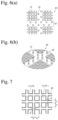
- FIG. 4 ( a ) is a front view schematically showing an example of connecting members used in the water-treating ceramic filter module of the present invention.
- FIG. 4 ( b ) is a plan view schematically showing the connecting member of FIG. 4 ( a ) .
- FIG. 5 ( a ) is an enlarged front view schematically showing a portion A in FIG. 4 ( a ) .
- FIG. 5 ( b ) is a cross-sectional view taken along the line C-C in FIG. 5 ( a ) .
- FIG. 6 ( a ) is an enlarged front view schematically showing a center portion of FIG. 4 ( a ) .
- FIG. 6 ( b ) is a perspective view of FIG. 6 ( a ) .
- FIG. 7 is a front view showing a connecting member attached to the honeycomb structure from the connecting member side.
- FIG. 8 is a schematic cross-sectional view showing a connecting portion of adjacent honeycomb structures in the filter unit.
- FIG. 9 ( a ) is a front view schematically showing an example of plugging members used in the water-treating ceramic filter module of the present invention.
- FIG. 9 ( b ) is a plan view schematically showing the plugging member of FIG. 9 ( a ) .
- FIG. 10 ( a ) is an enlarged front view schematically showing a portion B in FIG. 9 ( a ) .
- FIG. 10 ( b ) is a cross-sectional view taken along the line D-D in FIG. 10 ( a ) .
- FIG. 10 ( c ) is a perspective view of FIG. 10 ( a ) .
- FIG. 11 is a schematic cross-sectional view showing a plugging member attached to the honeycomb structure.
- FIG. 12 is a schematic view showing an example of fixing members used in the water-treating ceramic filter module of the present invention.
- FIG. 13 is a flow diagram schematically showing a water treatment facility comprising the water-treating ceramic filter module of the present invention.
- FIG. 14 is a schematic cross-sectional view showing the water-treating ceramic filter module of Comparative Example 1.
- FIG. 13 A water treatment facility to which the water-treating ceramic filter module of the present invention is applicable is first explained referring to FIG. 13 .
- the water-treating ceramic filter module 100 of the present invention is used, for example, in a water treatment facility 200 shown in the flow diagram of FIG. 13 .
- the water treatment facility 200 comprises the water-treating ceramic filter module 100 of the present invention, a water tank 201 storing water treated in the water-treating ceramic filter module 100 , a water-supplying pump 202 for supplying water from the water tank 201 , and a reverse osmosis membrane module 203 comprising reverse osmosis membranes 204 for removing separable materials from water supplied by the water-supplying pump 202 .
- the water-treating ceramic filter module 100 of the present invention conducts an upstream pretreatment step of selectively and efficiently adsorbing and removing organic materials, etc., which would contaminate the reverse osmosis membranes 204 in the downstream reverse osmosis membrane module 203 .
- the primarily treated water supplied to the water-treating ceramic filter module 100 of the present invention passes through the filter unit 101 comprising porous ceramic honeycomb structures inside the filter module 100 to remove these dissolved organic materials, etc. by adsorption, and then is stored in the water tank 201 temporally.
- the primarily treated water stored in the water tank 201 in a predetermined amount is supplied to and passes through the reverse osmosis membranes 204 , by which it is divided to permeating water with dissolved organic materials, etc. removed, and concentrated water in which the dissolved organic materials, etc. are concentrated.
- the water-treating ceramic filter module 100 of the present invention preliminarily removes the dissolved organic materials, etc. from the primarily treated water by adsorption to avoid the contamination of the reverse osmosis membranes 204 , thereby expanding the replacement life of the reverse osmosis membranes 204 .
- the water-treating ceramic filter module 100 of the present invention can be widely used in water treatment facilities comprising reverse osmosis membranes for the desalination of seawater, the production of pure water used in the production of precise electronic devices such as semiconductors, etc., the advanced treatment of tap water, the regeneration of drainage water and sewage water (including those not using microbes), etc.
- the water-treating ceramic filter module 100 of the present invention comprises a filter unit 101 , and a housing 110 containing the filter unit 101 ;
- the filter unit 101 being composed of pluralities of cylindrical honeycomb structures 11 , 11 ′, 11 ′′ having pluralities of flow paths 13 , 13 ′, 13 ′′ partitioned by porous ceramic cell walls 12 , 12 ′, 12 ′′ and extending in one direction (hereinafter referred to as “porous honeycomb structures” or “honeycomb structures”), and sheet-shaped connecting members 20 connecting pluralities of honeycomb structures 11 , 11 ′, 11 ′′ in series in the flow path direction; each connecting member 20 having pluralities of penetrating holes for the communication of corresponding flow paths 13 , 13 ′, 13 ′′ in adjacent honeycomb structures 11 , 11 ′, 11 ′′ to constitute pluralities of communicating flow paths 103 ;
- the communicating flow paths 103 being composed of
- the water-treating ceramic filter module 100 of the present invention uses the filter unit 101 constituted by pluralities of honeycomb structures 11 , 11 ′, 11 ′′ arranged in series in the flow path direction.
- the filter unit 101 in FIG. 2 has three honeycomb structures 11 , 11 ′, 11 ′′, the present invention is not restricted thereto.
- the filter unit may be constituted by two honeycomb structures, or four honeycomb structures or more.
- the honeycomb structures constituting the filter unit may have the same or different lengths in the flow path direction.
- the filter unit 101 comprises, in addition to the honeycomb structures 11 , 11 ′, 11 ′′, connecting members 20 connecting adjacent honeycomb structures 11 and 11 ′, and 11 ′ and 11 ′′, such that their corresponding flow paths are communicating with each other.
- the flow paths 13 , 13 ′, 13 ′′ constitute communicating flow paths 103 via the connecting members 20 .
- the filter unit 101 shown in FIG. 2 further comprises a first plugging member 30 b closing the one-side ends 101 a of the first communicating flow paths 103 b from which the treated water exits, and a second plugging member 30 a closing the other-side ends 101 b of the second communicating flow paths 103 a into which the water to be treated is introduced.
- these plugging members 30 first and second plugging members 30 b , 30 a ) may not be used.
- a peripheral (side) surface of the filter unit 101 may be surrounded by a water-impermeable member (not shown).
- the filter unit can have increased adsorption capacity without making each honeycomb structure bigger, thereby providing a water-treating ceramic filter module having improved efficiency by reducing the frequency of replacing adsorption structures.
- the filter unit 101 comprises the connecting members 20 connecting adjacent honeycomb structures (honeycomb structures 11 and 11 ′, and honeycomb structures 11 ′ and 11 ′′ in FIG. 2 ), such that their corresponding flow paths are communicating with each other.
- the corresponding flow paths of the honeycomb structures 11 , 11 ′, 11 ′′ constitute communicating flow paths 103 extending from the one-side end 101 a to the other-side end 101 b .
- FIGS. 4 ( a ) and 4 ( b ) show an example of the connecting members 20
- FIGS. 5 ( a ) and 5 ( b ) enlargedly show a portion A of the connecting member 20 of FIG. 4 ( a )
- Each connecting member 20 is a sheet-shaped member having the same shape as that of the honeycomb structure 11 when viewed in the direction of the flow paths 13 (the longitudinal direction), which comprises penetrating holes 21 arranged at positions corresponding to predetermined flow paths 13 of the honeycomb structure 11 , and projections 22 arranged on both sides to be fit into particular flow paths 13 .
- the projections 22 are fit into the corresponding flow paths 13 , to facilitate the positioning of the penetrating holes 21 of the connecting member 20 to the flow paths 13 of the honeycomb structure 11 .
- the projections 22 are preferably tapered for easy fitting into the flow paths 13 .
- the projections 22 are preferably arranged on both sides of the belt-like region 23 free from penetrating holes 21 , further preferably in a staggering pattern, thereby making easier the positioning of the penetrating holes 21 of the connecting member 20 to the flow paths 13 of the honeycomb structure 11 . Because there are no penetrating holes 21 in the belt-like region 23 , the flow paths are shut in this region, providing no communicating flow paths 103 . Because water does not flow in the flow paths not constituting the communicating flow paths 103 , the cell walls forming such flow paths do not contribute to the removal of the dissolved organic materials, etc. by adsorption. To have as many communicating flow paths 103 contributing to the purification of water as possible, the belt-like region 23 is preferably as narrow as possible in such a range as to secure enough positioning precision.
- the projections 22 are arranged in a staggering pattern in a cross-shaped belt-like region 23 passing a center of the connecting member 20 .
- the cross-shaped belt-like region 23 passing a center of the connecting member 20 provides good balance between the assured positioning of the penetrating holes 21 of the connecting member 20 to the flow paths 13 of the honeycomb structure 11 , and the distribution of the communicating flow paths 103 when viewed in the longitudinal direction of the filter unit 101 , though the shape of the belt-like region 23 is not restricted to a cross but may have any shape.
- the projections 22 are arranged in a staggering pattern. Namely, the projections 22 are arranged in two lines in the longitudinal direction of the belt-like region 23 , with intervals of the projections 22 in each line as wide as two times those of the penetrating holes 21 , such that the projections 22 in each line are arranged alternately in the width direction (transverse direction) of the belt-like region 23 .
- Such arrangement of the projections 22 makes positioning easy in the fitting of the projections 22 into the flow paths 13 .
- FIG. 7 is a front view showing the connecting member 20 attached to the honeycomb structure 11 from the side of the connecting member 20 .
- the honeycomb structure 11 shown in FIG. 7 has lattice-patterned cell walls 12 , providing square flow paths 13 when viewed in the longitudinal direction.
- Each penetrating hole 21 of the connecting member 20 preferably has an area equal to or larger than the opening area of each flow path 13 of the honeycomb structure 11 , such that the penetrating hole 21 does not hinder the flow of water.
- the distance d′ between adjacent penetrating holes 21 and 21 of the connecting member 20 is preferably equal to or less than the thickness d of the cell walls 12 of the honeycomb structure 11 .
- FIG. 8 is a schematic cross-sectional view showing adjacent honeycomb structures 11 and 11 ′ connected via the connecting member 20 in the filter unit. Because the honeycomb structures 11 and 11 ′ have the same shape, communicating flow paths 103 are formed by connecting their corresponding flow paths 13 , 13 ′. However, flow paths 13 , 13 ′ facing the belt-like region 23 are shut by the belt-like region 23 , failing to constitute communicating flow paths 103 .
- the connecting member 20 is preferably made of elastic materials (materials having a large elastic range) easily filling small surface roughness of the honeycomb structures 11 , 11 ′, 11 ′′, for example, at least one of silicone rubber, fluororubber, ethylene-propylene-diene rubber, and nitrile-butadiene rubber, though not restrictive. It may be formed by corrosion-resistant metals such as SUS304, SUS316, SUS316L, MAT21 (registered trademarks), etc.
- Water introduced through the inlet 112 a of the water-treating ceramic filter module 100 flows through the filter unit 101 with the dissolved organic materials, etc. removed, and exits from the outlet 113 a . While water passes through the filter unit 101 , the organic materials, etc. dissolved in water are removed by adsorption onto surfaces of pores inside the porous ceramic cell walls 12 , 12 ′, 12 ′′.
- part of the communicating flow paths 103 in the filter unit 101 are composed of first communicating flow paths 103 b closed only at the one-side end 101 a , and second communicating flow paths 103 a closed only at the other-side end 101 b.
- water to be treated does not enter the first communicating flow paths 103 b closed at the one-side end 101 a , but flows into the second communicating flow paths 103 a open at the one-side end 101 a .
- the second communicating flow paths 103 a are plugged at the other-side end 101 b , the water inevitably flows through the cell walls 12 , 12 ′, 12 ′′ to the first communicating flow paths 103 b open at the other-side end 101 b .
- the second communicating flow paths 103 a are preferably adjacent to the first communicating flow paths 103 b.
- FIGS. 9 ( a ) and 9 ( b ) show an example of the plugging members 30 (first plugging member 30 b and second plugging member 30 a ), and FIGS. 10 ( a ), 10 ( b ) and 10 ( c ) enlargedly show a portion B of the plugging member 30 of FIG. 9 ( a ) .
- the plugging member 30 comprises penetrating holes 31 and plugs 32 aligned with the flow paths 13 , 13 ′′ of the honeycomb structures 11 , 11 ′′. As shown in FIG.
- the filter unit 101 preferably comprises the first plugging member 30 b having pluralities of plugs 32 for closing the first communicating flow paths 103 b at the one-side end 101 a , and the second plugging member 30 a having pluralities of plugs 32 for closing the second communicating flow paths 103 a at the other-side end 101 b .
- the first plugging member 30 b has water-flowable holes 31 at positions corresponding to the second communicating flow paths 103 a
- the second plugging member 30 a has water-flowable holes 31 at positions corresponding to the first communicating flow paths 103 b.
- the first and second plugging members 30 b , 30 a need only be different, such that when they are oppositely attached to the filter unit 101 at the one-side end 101 a (the water to be treated is supplied) and the other-side end 101 b (the treated water exits), respectively, both ends of individual communicating flow paths 103 are not closed by their plugs 32 .
- the plugging member 30 at the one-side end 101 a which is the first plugging member 30 b , comprises the plugs 32 closing the one-side ends 101 a of the first communicating flow paths 103 b , and holes (inlet holes) 31 aligned with the second communicating flow paths 103 a
- the plugging member 30 at the other-side end 101 b which is the second plugging member 30 a , comprises the plugs 32 closing the other-side ends 101 b of the second communicating flow paths 103 a and holes (outlet holes) 31 aligned with the first communicating flow paths 103 b .
- both ends of the filter unit 101 are easily plugged to constitute the first communicating flow paths 103 b and the second communicating flow paths 103 a .
- honeycomb structures 11 , 11 ′′ having plugged portions in advance need not be used, and all honeycomb structures 11 , 11 ′, 11 ′′ constituting the filter unit 101 can be free of plugged portions, making it unnecessary to use honeycomb structures with different shapes, thereby achieving standardization and thus suppressing production cost.
- first plugging member 30 b is attached to the one-side end 101 a of the filter unit 101
- the structure and operation of the first plugging member 30 b will be explained below.
- the second plugging member 30 a is attached to the other-side end 101 b of the filter unit 101 , thereby omitting its explanation.
- the holes 31 and the plugs 32 are aligned with the flow paths 13 open on the one-side end 101 a of the honeycomb structure 11 .
- the plugs 32 are fit into the corresponding flow paths 13 , facilitating the positioning of the holes 31 of the first plugging member 30 b to the flow paths 13 of the honeycomb structure 11 to close the flow paths 13 corresponding to the plugs 32 .
- the plugs 32 are preferably tapered for easy fitting into the flow paths 13 .
- FIG. 11 is a cross-sectional view showing the first plugging member 30 b attached to the honeycomb structure 11 .
- the flow paths 13 are closed by the plugs 32 , constituting the first communicating flow paths 103 b .
- each hole 31 of the first plugging member 30 b preferably has an area equal to or larger than the opening area of each corresponding flow path 13 of the honeycomb structure 11 .
- the first plugging member 30 b and the second plugging member 30 a may be different as long as their plugs 32 do not close both ends of individual communicating flow paths 103 as described above, and other portions of them may be the same.
- the plugging member 30 shown in FIGS. 9 - 11 is preferably a sheet having the same shape as that of the honeycomb structure 11 when viewed in the longitudinal direction. This shape further facilitates the positioning of the holes 31 of the plugging member 30 to the flow paths 13 , though this shape is not necessarily restrictive.
- the plugging member 30 may have any thickness, and is not restricted to a sheet shape.
- the plugging members 30 are preferably made of elastic materials (materials having a large elastic range) easily deformable along the surfaces of the honeycomb structures 11 , 11 ′′, for example, at least one of silicone rubber, fluororubber, ethylene-propylene-diene rubber, and nitrile-butadiene rubber, though not restrictive. It may be formed by corrosion-resistant metals such as SUS304, SUS316, SUS316L, MAT21 (registered trademarks), etc.
- each honeycomb structure 11 ( 11 ′, 11 ′′) constituting the filter unit 101 has a cylindrical shape having pluralities of flow paths 13 ( 13 ′, 13 ′′) partitioned by porous ceramic cell walls 12 ( 12 ′, 12 ′′).
- the honeycomb structure 11 ( 11 ′, 11 ′′) has a honeycomb shape having pluralities of longitudinally extending flow paths 13 ( 13 ′, 13 ′′).
- Porous ceramic materials include cordierite, alumina, silica, magnesia, titania, etc. Though not restrictive as long as porous honeycomb structures can be formed, easily moldable cordierite or alumina having a small thermal expansion coefficient is preferable.
- the honeycomb structure 11 ( 11 ′, 11 ′′) may comprise an outer peripheral (side) wall obtained by sintering a coating material containing cordierite particles and colloidal silica, etc.
- the pores formed in the cell walls 12 ( 12 ′, 12 ′′) have a median pore diameter of preferably 1-50 ⁇ m, more preferably 5-30 ⁇ m, and further preferably 10-20 ⁇ m.
- the median pore diameter is a pore diameter at a pore volume corresponding to 50% of the total pore volume, in a curve exhibiting the relation between pore diameter and cumulative pore volume in the cell walls.
- the cell walls 12 ( 12 ′, 12 ′′) preferably have porosity of 25-70%.
- porosity of the cell walls 12 ( 12 ′, 12 ′′) is 25% or more, an adsorbing material described below can easily be carried by the cell walls without closing the communicating pores.
- the porosity of the cell walls 12 ( 12 ′, 12 ′′) is 70% or less, the cell walls 12 ( 12 ′, 12 ′′) have such mechanical strength that they are not broken by water pressure or shock in assembling into the housing.
- the cell walls 12 ( 12 ′, 12 ′′) of the honeycomb structure 11 are preferably in a lattice pattern when viewed in the longitudinal direction.
- FIG. 3 shows a honeycomb structure 11 having lattice-shaped cell walls 12 forming square flow paths 13 when viewed in the longitudinal direction.
- the cell walls 12 ( 12 ′, 12 ′′) preferably have thickness d of 0.1-2 mm, and a ratio d/w of the thickness d to the width w of flow paths 13 ( 13 ′, 13 ′′) formed by the cell walls 12 ( 12 ′, 12 ′′) preferably meets the relation of 0.25 ⁇ d/w ⁇ 1.25.
- the cell walls 12 ( 12 ′, 12 ′′) When the thickness of the cell walls 12 ( 12 ′, 12 ′′) is 0.1 mm or more, and/or when 0.25 ⁇ d/w is met, the cell walls 12 ( 12 ′, 12 ′′) have such mechanical strength that they are not broken by water pressure or shock in assembling into the housing. Also, because of sufficiently long communicating pores, metal oxide particles, etc. exhibiting sufficient adsorption performance can be carried. When the thickness of the cell walls 12 ( 12 ′, 12 ′′) is 2 mm or less, and/or when d/w ⁇ 1.25 is met, pressure necessary for permeating water can be low, enabling the water treatment with high energy efficiency.
- the honeycomb structure 11 shown in FIGS. 3 ( a ), 3 ( b ) and 7 has square flow paths 13 ( 13 ′, 13 ′′) when viewed in the longitudinal direction.
- Each flow path 13 ( 13 ′, 13 ′′) is preferably in a square shape having a width (length of one side) w of 0.5-8 mm when viewed in the longitudinal direction.
- the width (length of one side) w of the flow paths 13 ( 13 ′, 13 ′′) is 0.5 mm or more, foreign matter other than the dissolved organic materials, etc. unlikely clogs the openings of the second communicating flow paths 103 a of the filter unit 101 , slowing down performance decrease.
- each flow path 13 ( 13 ′, 13 ′′) when viewed in the longitudinal direction is not restricted to be square as shown in FIG. 3 ( b ) , but may be in any other shapes such as tetragon (rectangle, etc.), triangle, hexagon, etc., or their combinations.
- the cell walls 12 may carry an adsorbing material for improving adsorption performance.
- the adsorbing materials include the above ceramics (metal oxides), as well as resins such as nylons, aramides, polyamides, celluloses, polyethylene, etc., and these materials are selected for objects to be removed because of adsorption selectivity.
- the metal oxide particles include particles of ⁇ -alumina, ⁇ -alumina, zinc oxide, copper oxide, etc.
- the thickness of the adsorbing material carried is on such a level as not undesirably lowering the water pressure, preferably an average thickness of 1/10 or less of the median pore diameter of cell walls. The average thickness is determined by dividing a volume calculated from the amount (weight) and specific gravity of the adsorbing material carried, by the specific surface area of the honeycomb structure measured by a mercury porosimeter, etc.
- the housing 110 constituting the water-treating ceramic filter module 100 of the present invention comprises a filter container 111 receiving the filter unit 101 , a funnel-shaped inlet part 112 arranged on the supply side of the water to be treated, and a funnel-shaped exit part 113 arranged on the side of discharging the treated water.
- the water to be treated which is supplied through the inlet 112 a of the inlet part 112 evenly expands toward the one-side end 101 a of the filter unit 101 due to the funnel shape of the inlet part 112 , flows into the second communicating flow paths 103 a , and passes through the communicating pores (not shown) of the cell walls 12 , 12 ′, 12 ′′ to enter the first communicating flow paths 103 b .
- the dissolved organic materials, etc. are removed to provide the treated water.
- the treated water passing through the first communicating flow paths 103 b and exiting from the other-side end 101 b is converged by the funnel shape of the exit part 113 , and then discharged from the outlet 113 a.
- the flanges 111 b of the filter container 111 are fixed to the flanges 112 b , 113 b of the inlet and exit parts 112 , 113 by bolts, etc. (not shown), to constitute an integral housing 110 .
- the filter container 111 is preferably in a cylinder shape having substantially the same length as that of the filter unit 101 , and necessary and sufficient inner shape and size (viewed in the longitudinal direction) for containing the filter unit 101 .
- the housing 110 is preferably made of materials resistant to seawater and aqueous alkaline solutions, such as metals such as SUS304, SUS316, etc., resins such as hard polyvinyl chloride (PVC), polyethylene (PE), etc.
- the filter container 111 , the inlet part 112 and the exit part 113 may be made of the same or different materials.
- the inlet and exit parts 112 , 113 and the filter container 111 are fixed to press the filter unit 101 in the flow path direction, thereby tightly attaching the connecting members and the plugging members to the honeycomb structure to secure water tightness inside the housing 110 .
- ring members 115 are preferably disposed between the flanges 111 b and 112 b , and 111 b and 113 b , to provide higher water tightness.
- the flange 112 b of the inlet part 112 and the flange 113 b of the exit part 113 extend from positions slightly inside the filter container 111 , overlapping peripheral portions of the one-side and other-side ends 101 a , 101 b of the filter unit 101 , with sealing members 114 disposed between these peripheral portions and the flanges 112 b , 113 b .
- the sealing members 114 more preferably increase water tightness, and surely fix the filter unit 101 inside the housing 110 .
- the water-treating filter module 100 may further comprise fixing members 40 shown in FIG. 12 .
- the fixing member 40 is attached to an outer surface of each plugging member 30 mounted to the filter unit 101 , to push the plugging member 30 .
- the fixing members 40 prevent the plugging members 30 from detaching by water pressure, and increase the attachment tightness of the plugging members 30 to the honeycomb structures 11 , 11 ′′, thereby preventing water leak from the communicating flow paths 103 plugged by the plugging members 30 , particularly from the second communicating flow paths 103 a , into which the water to be treated is introduced, to the other-side end 101 b .
- the fixing members 40 may be made of any material, as long as they prevent the plugging members 30 from detaching by water pressure, are strong enough to avoid easy deformation and substantially insoluble in water.
- resins such as polyethylene, polypropylene, polyethylene terephthalate, polystyrene, etc., and metals such as stainless steel, titanium alloys, etc. can be used.
- Powders of kaolin, talc, silica, aluminum hydroxide and alumina were mixed to obtain a cordierite-forming powder having a chemical composition comprising 50% by mass of SiO 2 , 36% by mass of Al 2 O 3 , and 14% by mass of MgO.
- This cordierite-forming powder was mixed with methyl cellulose and hydroxypropyl methyl cellulose as molding aids, and thermally expandable microcapsule as a pore-forming material, and sufficiently blended with a proper amount of ion-exchanged water to prepare a material extrusion-moldable to a honeycomb structure.
- the moldable material was extruded to form a honeycomb-structure green body, which was dried, machined to remove its peripheral portion, and sintered at 1400° C. for 24 hours to obtain a sintered cylindrical honeycomb structure.
- An outer peripheral surface of the sintered honeycomb structure was coated with a coating material containing cordierite particles and colloidal silica, dried and then sintered, to obtain a cylindrical porous ceramic honeycomb structure of 127 mm in outer diameter and 152.4 mm in length, which had square flow paths of 0.76 mm in cell wall thickness and 2.75 mm in cell pitch when viewed in the longitudinal direction.
- Three honeycomb structures 11 , 11 ′, 11 ′′, two connecting members 20 each of which was a silicone rubber sheet of 127 mm in diameter and 2.0 mm in thickness having a region in which penetrating holes 21 of 2.0 mm in each side were provided at a pitch of 2.75 mm, and a belt-like region 23 in which projections 22 of 1.4 mm in diameter and 2.0 mm in height were arranged in a staggering pattern [see FIGS.
- first and second plugging members 30 b , 30 a each of which was a silicone rubber sheet of 127 mm in diameter and 3.0 mm in thickness, and had holes 31 of 2.0 mm in each side and plugs 32 of 2.0 mm in height alternately arranged at a pitch of 2.75 mm in a staggering pattern [see FIGS. 9 ( a ) and 9 ( b ) ] were prepared. As shown in FIG.
- the honeycomb structures 11 , 11 ′, 11 ′′ were connected in series via the connecting members 20 , and the first plugging member 30 b was attached to the one-side end 101 a of the honeycomb structure 11 , and the second plugging member 30 a was attached to the other-side end 101 b of the honeycomb structure 11 ′′, to produce a filter unit 101 comprising first communicating flow paths 103 b penetrating to the other-side end 101 b and plugged only at the one-side end 101 a , and second communicating flow paths 103 a penetrating to the one-side end 101 a and plugged only at the other-side end 101 b.
- a filter container 111 of SUS304 having an outer diameter of 137 mm and a length of 467.2 mm, funnel-shaped inlet and exit parts 112 , 113 of SUS304 each having an outer diameter of 137 mm, ring-shaped sealing members 114 of a nitrile-butadiene rubber each having a thickness of 4.0 mm, and fixing members 40 were assembled in the housing 110 as described below, to produce the water-treating ceramic filter module 100 of the present invention shown in FIG. 1 .
- the filter container 111 was arranged to cover the side surface of the filter unit 101 , and the flange 111 b of the filter unit 101 and the flange 112 b of the inlet part 112 were fixed by bolts and nuts.
- the fixing members 40 and the sealing members 114 were successively placed on the filter unit 101 , and the flange 111 b of the filter unit 101 and the flange 113 b of the exit part 113 were fixed by bolts and nuts to obtain a water-treating ceramic filter module 100 .
- the artificial contaminated water was circulated through the water-treating ceramic filter module 100 of Example 1, by a method of introducing it into the inlet 112 a , discharging it from the outlet 113 a , and introducing it into the inlet 112 a again. Circulation was stopped when the turbidity of the circulated artificial contaminated water reached the same level as that of the tapped water, and the filter unit 101 was taken out and disassembled to measure the amount and distribution of SiC particles captured in each honeycomb structure 11 , 11 ′, 11 ′′.
- a plugging slurry of a cordierite-forming material was charged into flow path end portions of a sintered honeycomb structure produced in the same manner as in Example 1, such that inlet and exit end portions of the flow paths were alternately plugged. Thereafter, the plugging material slurry was dried and sintered. After forming the plugs, an outer peripheral surface of the ceramic honeycomb structure was coated with a coating material containing cordierite particles and colloidal silica, dried, and sintered to obtain a cylindrical porous ceramic honeycomb filter of 127 mm in outer diameter and 152.4 mm in length, which had square flow paths of 0.76 mm in cell wall thickness and 2.75 mm in cell pitch when viewed in the longitudinal direction.
- the water-treating ceramic filter module 300 of Comparative Example 1 differs from the water-treating ceramic filter module 100 of Example 1, in that each of three porous ceramic honeycomb filters 301 , 301 ′, 301 ′′ is alternately plugged in inlet and exit end portions of the flow paths, and that all porous ceramic honeycomb filters 301 , 301 ′, 301 ′′ are separated from each other. Accordingly, The water-treating ceramic filter module 300 of Comparative Example 1 does not have communicating flow paths 103 penetrating all of the three filters, unlike the filter unit 101 of Example 1.
- porous ceramic honeycomb filters 301 , 301 ′, 301 ′′ When the performance is not fully recovered by repeated backwashing, the replacement of porous ceramic honeycomb filters 301 , 301 ′, 301 ′′ is needed. Long continuous use could not be achieved by the water-treating ceramic filter module 300 of Comparative Example 1, because the porous ceramic honeycomb filter 301 on the supply side of water to be treated should be frequently replaced.
- the water-treating ceramic filter module 100 of Example 1 needed only less frequent backwashing, and easily recovered performance by one backwashing operation, thereby reducing the number of replacement operations of the filter unit 101 . Accordingly, it enjoyed higher efficiency, maintaining the performance for a long period of time.
Landscapes
- Chemical & Material Sciences (AREA)
- Chemical Kinetics & Catalysis (AREA)
- Organic Chemistry (AREA)
- Inorganic Chemistry (AREA)
- Analytical Chemistry (AREA)
- Engineering & Computer Science (AREA)
- Life Sciences & Earth Sciences (AREA)
- Environmental & Geological Engineering (AREA)
- Water Supply & Treatment (AREA)
- Hydrology & Water Resources (AREA)
- Ceramic Engineering (AREA)
- Geology (AREA)
- Filtering Materials (AREA)
- Separation Using Semi-Permeable Membranes (AREA)
- Water Treatment By Sorption (AREA)
Abstract
Description
- 100: Water-treating ceramic filter module
- 101: Filter unit
- 101 a: One-side end
- 101 b: The other-side end
- 103: Communicating flow path
- 103 a: Second communicating flow path
- 103 b: First communicating flow path
- 11, 11′, 11″: Honeycomb structure
- 12, 12′, 12″: Cell wall
- 13, 13′, 13″: Flow path
- 20: Connecting member
- 21: Penetrating hole
- 22: Projection
- 23: Belt-like region
- 24: Peripheral portion
- 30: Plugging member
- 30 a: Second plugging member
- 30 b: First plugging member
- 31: Hole
- 32: Plug
- 40: Fixing member
- 110: Housing
- 111: Filter container
- 112: Inlet part
- 113: Exit part
- 112 a: Inlet
- 113 a: Outlet
- 111 b, 112 b, 113 b: Flange
- 114: Sealing member
- 115: Ring member
- 200: Water treatment facility
- 201: Water tank
- 202: Water-supplying pump
- 203: Reverse osmosis membrane module
- 204: Reverse osmosis membrane
- 300: Water-treating ceramic filter module
- 301, 301′, 301″: Porous ceramic honeycomb filter
- 310: Housing
- 311: Filter container
- 312: Inlet part
- 313: Exit part
- 312 a: Inlet
- 313 a: Outlet
- 314: Sealing member
- 315: Ring member
Claims (14)
Applications Claiming Priority (3)
| Application Number | Priority Date | Filing Date | Title |
|---|---|---|---|
| JP2018-017302 | 2018-02-02 | ||
| JP2018017302 | 2018-02-02 | ||
| PCT/JP2019/003923 WO2019151522A1 (en) | 2018-02-02 | 2019-02-04 | Ceramic filter module for water treatment |
Publications (2)
| Publication Number | Publication Date |
|---|---|
| US20200346149A1 US20200346149A1 (en) | 2020-11-05 |
| US11712648B2 true US11712648B2 (en) | 2023-08-01 |
Family
ID=67479282
Family Applications (1)
| Application Number | Title | Priority Date | Filing Date |
|---|---|---|---|
| US16/962,656 Active 2040-05-09 US11712648B2 (en) | 2018-02-02 | 2019-02-04 | Water-treating ceramic filter module |
Country Status (5)
| Country | Link |
|---|---|
| US (1) | US11712648B2 (en) |
| EP (1) | EP3718974B1 (en) |
| JP (1) | JP7259768B2 (en) |
| ES (1) | ES2983730T3 (en) |
| WO (1) | WO2019151522A1 (en) |
Families Citing this family (3)
| Publication number | Priority date | Publication date | Assignee | Title |
|---|---|---|---|---|
| US11819787B2 (en) * | 2018-06-12 | 2023-11-21 | Proterial, Ltd. | Water-treating ceramic filter unit |
| JP7547903B2 (en) * | 2020-09-29 | 2024-09-10 | 株式会社プロテリアル | Joint member, filter unit using said joint member, and ceramic filter module for water treatment having said filter unit |
| CN120268251B (en) * | 2025-05-22 | 2026-02-27 | 浙江泓元新材料有限公司 | Recrystallized silicon carbide honeycomb ceramic film for water treatment and preparation method thereof |
Citations (17)
| Publication number | Priority date | Publication date | Assignee | Title |
|---|---|---|---|---|
| JPS6320012A (en) | 1986-07-15 | 1988-01-27 | Ngk Insulators Ltd | Filter device |
| JPS63201623U (en) | 1987-06-12 | 1988-12-26 | ||
| US4830749A (en) | 1986-07-15 | 1989-05-16 | Ngk Insulators, Ltd. | Liquid waste filtering apparatus |
| US5194154A (en) | 1991-12-05 | 1993-03-16 | The Dow Chemical Company | Structure for filter or heat exchanger, composed of a fused single crystal acicular ceramic |
| WO1993011087A1 (en) | 1991-12-05 | 1993-06-10 | The Dow Chemical Company | Structure for a filter or a heat exchanger and a method for making the structure |
| JP2001205108A (en) | 2000-01-24 | 2001-07-31 | Toyota Motor Corp | Particulate filter |
| JP2003117335A (en) | 2001-10-10 | 2003-04-22 | Kobe Steel Ltd | Housing container for honeycomb filter |
| JP2004075522A (en) | 2002-06-17 | 2004-03-11 | Hitachi Metals Ltd | Ceramic honeycomb structure |
| US20040161373A1 (en) | 2003-02-18 | 2004-08-19 | Ngk Insulators, Ltd. | Honeycomb filter and exhaust gas purification system |
| JP2006150276A (en) | 2004-11-30 | 2006-06-15 | Hitachi Metals Ltd | Honeycomb filter |
| US20090202402A1 (en) | 2008-02-13 | 2009-08-13 | Ibiden Co., Ltd. | Honeycomb structure, exhaust gas purifying apparatus and method for manufacturing honeycomb structure |
| JP2012091151A (en) | 2010-10-29 | 2012-05-17 | Hitachi Ltd | Adsorption structure, adsorption module, and method for producing the same |
| JP2013223827A (en) | 2012-04-20 | 2013-10-31 | Kubota Corp | Membrane element |
| JP2015054802A (en) | 2013-09-13 | 2015-03-23 | 株式会社クボタ | Method for producing ceramic structure, method for producing membrane element, joining material and method for producing the joining material |
| JP2016198742A (en) | 2015-04-13 | 2016-12-01 | 日立金属株式会社 | Solution processing system, solution processing apparatus, and solution processing method |
| JP6216847B2 (en) | 2016-08-22 | 2017-10-18 | 株式会社日立製作所 | Reverse osmosis processing equipment |
| JP2018183745A (en) | 2017-04-26 | 2018-11-22 | 日立金属株式会社 | Adsorption structure, adsorption structure unit and manufacturing method thereof |
Family Cites Families (1)
| Publication number | Priority date | Publication date | Assignee | Title |
|---|---|---|---|---|
| JPS5634523A (en) | 1979-08-27 | 1981-04-06 | Shin Meiwa Ind Co Ltd | Emergency stop device for driven object of concrete mixer truck |
-
2019
- 2019-02-04 EP EP19748175.7A patent/EP3718974B1/en active Active
- 2019-02-04 JP JP2019569635A patent/JP7259768B2/en active Active
- 2019-02-04 WO PCT/JP2019/003923 patent/WO2019151522A1/en not_active Ceased
- 2019-02-04 US US16/962,656 patent/US11712648B2/en active Active
- 2019-02-04 ES ES19748175T patent/ES2983730T3/en active Active
Patent Citations (20)
| Publication number | Priority date | Publication date | Assignee | Title |
|---|---|---|---|---|
| JPS6320012A (en) | 1986-07-15 | 1988-01-27 | Ngk Insulators Ltd | Filter device |
| US4830749A (en) | 1986-07-15 | 1989-05-16 | Ngk Insulators, Ltd. | Liquid waste filtering apparatus |
| JPS63201623U (en) | 1987-06-12 | 1988-12-26 | ||
| US5194154A (en) | 1991-12-05 | 1993-03-16 | The Dow Chemical Company | Structure for filter or heat exchanger, composed of a fused single crystal acicular ceramic |
| WO1993011087A1 (en) | 1991-12-05 | 1993-06-10 | The Dow Chemical Company | Structure for a filter or a heat exchanger and a method for making the structure |
| JP2001205108A (en) | 2000-01-24 | 2001-07-31 | Toyota Motor Corp | Particulate filter |
| JP2003117335A (en) | 2001-10-10 | 2003-04-22 | Kobe Steel Ltd | Housing container for honeycomb filter |
| JP2004075522A (en) | 2002-06-17 | 2004-03-11 | Hitachi Metals Ltd | Ceramic honeycomb structure |
| US20040161373A1 (en) | 2003-02-18 | 2004-08-19 | Ngk Insulators, Ltd. | Honeycomb filter and exhaust gas purification system |
| JP2004251137A (en) | 2003-02-18 | 2004-09-09 | Ngk Insulators Ltd | Honeycomb filter and exhaust emission control system |
| JP2006150276A (en) | 2004-11-30 | 2006-06-15 | Hitachi Metals Ltd | Honeycomb filter |
| US20090202402A1 (en) | 2008-02-13 | 2009-08-13 | Ibiden Co., Ltd. | Honeycomb structure, exhaust gas purifying apparatus and method for manufacturing honeycomb structure |
| US20120168995A1 (en) | 2008-02-13 | 2012-07-05 | Ibiden Co., Ltd. | Method for manufacturing honeycomb structure |
| JP2012091151A (en) | 2010-10-29 | 2012-05-17 | Hitachi Ltd | Adsorption structure, adsorption module, and method for producing the same |
| JP2013223827A (en) | 2012-04-20 | 2013-10-31 | Kubota Corp | Membrane element |
| JP2015054802A (en) | 2013-09-13 | 2015-03-23 | 株式会社クボタ | Method for producing ceramic structure, method for producing membrane element, joining material and method for producing the joining material |
| JP2016198742A (en) | 2015-04-13 | 2016-12-01 | 日立金属株式会社 | Solution processing system, solution processing apparatus, and solution processing method |
| JP6216847B2 (en) | 2016-08-22 | 2017-10-18 | 株式会社日立製作所 | Reverse osmosis processing equipment |
| JP2018183745A (en) | 2017-04-26 | 2018-11-22 | 日立金属株式会社 | Adsorption structure, adsorption structure unit and manufacturing method thereof |
| US20200048110A1 (en) | 2017-04-26 | 2020-02-13 | Hitachi Metals, Ltd. | Adsorption structure, adsorption structure unit, and method for manufacturing same |
Non-Patent Citations (4)
| Title |
|---|
| Communication dated Feb. 15, 2021, from the European Patent Office in EP Application No. 19748175.7. |
| English Machine Translation of JP2015054802A (Year: 2015). * |
| International Search Report for PCT/JP2019/003923 dated Apr. 23, 2019 [PCT/ISA/210]. |
| Notice of Reasons for Refusal dated Sep. 13, 2022 from the Japan Patent Office in Japanese Application No. 2019-569635. |
Also Published As
| Publication number | Publication date |
|---|---|
| US20200346149A1 (en) | 2020-11-05 |
| EP3718974B1 (en) | 2024-04-03 |
| ES2983730T3 (en) | 2024-10-24 |
| EP3718974A1 (en) | 2020-10-07 |
| JPWO2019151522A1 (en) | 2021-01-14 |
| JP7259768B2 (en) | 2023-04-18 |
| WO2019151522A1 (en) | 2019-08-08 |
| EP3718974A4 (en) | 2021-03-17 |
Similar Documents
| Publication | Publication Date | Title |
|---|---|---|
| US11712648B2 (en) | Water-treating ceramic filter module | |
| KR101048461B1 (en) | Filtration device | |
| EP3805162A1 (en) | Device for purifying scrubber drainage water, method for same, and salinity gradient power system | |
| JP2004261649A (en) | Filter and filter module | |
| EP3808708B1 (en) | Ceramic filter unit for water treatment | |
| US11547971B2 (en) | Ceramic filter membrane module | |
| EP3617157B1 (en) | Adsorption structure unit and method for manufacturing same | |
| JP7547903B2 (en) | Joint member, filter unit using said joint member, and ceramic filter module for water treatment having said filter unit | |
| JP5581086B2 (en) | Ceramic filter module | |
| JP2005270811A (en) | Filter | |
| JP4264017B2 (en) | Filter | |
| JP2005270810A (en) | Filter apparatus | |
| WO2007004263A1 (en) | Filter | |
| CN207356708U (en) | A kind of multimedium ceramic membrane filter system for the processing of lead-acid accumulator spent acid | |
| CN112897725A (en) | Filtering system and filtering device | |
| RU2661215C1 (en) | Water cartridge filtering unit for water treating | |
| KR102944018B1 (en) | Self-cleaning water purification filtration device utilizing a non-powered rotary cleaning module | |
| CN214693565U (en) | Novel filtering device | |
| CN202046921U (en) | Novel industrial waste water treatment reactor | |
| JP4271066B2 (en) | Filtration device and header for filtration device | |
| KR20070025918A (en) | Filtration | |
| CN112876000A (en) | Novel filtering process | |
| WO2007004261A1 (en) | Filter | |
| JP2009023264A (en) | Concrete mixer | |
| WO2007004264A1 (en) | Filtration device and header for filtration device |
Legal Events
| Date | Code | Title | Description |
|---|---|---|---|
| AS | Assignment |
Owner name: HITACHI METALS, LTD., JAPAN Free format text: ASSIGNMENT OF ASSIGNORS INTEREST;ASSIGNORS:KATAYAMA, YOSHIO;NAKANO, KEIKO;SIGNING DATES FROM 20200323 TO 20200327;REEL/FRAME:053230/0477 |
|
| FEPP | Fee payment procedure |
Free format text: ENTITY STATUS SET TO UNDISCOUNTED (ORIGINAL EVENT CODE: BIG.); ENTITY STATUS OF PATENT OWNER: LARGE ENTITY |
|
| STPP | Information on status: patent application and granting procedure in general |
Free format text: DOCKETED NEW CASE - READY FOR EXAMINATION |
|
| STPP | Information on status: patent application and granting procedure in general |
Free format text: NON FINAL ACTION MAILED |
|
| AS | Assignment |
Owner name: PROTERIAL, LTD., JAPAN Free format text: CHANGE OF NAME;ASSIGNOR:HITACHI METALS, LTD.;REEL/FRAME:063875/0550 Effective date: 20230112 |
|
| AS | Assignment |
Owner name: HITACHI METALS, LTD., JAPAN Free format text: CHANGE OF ADDRESS;ASSIGNOR:HITACHI METALS, LTD.;REEL/FRAME:063877/0864 Effective date: 20220705 |
|
| STPP | Information on status: patent application and granting procedure in general |
Free format text: PUBLICATIONS -- ISSUE FEE PAYMENT VERIFIED |
|
| STCF | Information on status: patent grant |
Free format text: PATENTED CASE |