US11708953B2 - Headlight optical element, headlight module, vehicle headlight and vehicle - Google Patents
Headlight optical element, headlight module, vehicle headlight and vehicle Download PDFInfo
- Publication number
- US11708953B2 US11708953B2 US16/965,178 US201916965178A US11708953B2 US 11708953 B2 US11708953 B2 US 11708953B2 US 201916965178 A US201916965178 A US 201916965178A US 11708953 B2 US11708953 B2 US 11708953B2
- Authority
- US
- United States
- Prior art keywords
- light
- headlight
- optical element
- ball
- transmitting portion
- Prior art date
- Legal status (The legal status is an assumption and is not a legal conclusion. Google has not performed a legal analysis and makes no representation as to the accuracy of the status listed.)
- Active, expires
Links
- 230000003287 optical effect Effects 0.000 title claims abstract description 115
- 230000002093 peripheral effect Effects 0.000 claims description 13
- 230000008033 biological extinction Effects 0.000 claims description 9
- 238000000576 coating method Methods 0.000 claims description 9
- 230000007246 mechanism Effects 0.000 claims description 9
- 239000011248 coating agent Substances 0.000 claims 1
- 238000004519 manufacturing process Methods 0.000 description 13
- 239000000243 solution Substances 0.000 description 13
- 238000002310 reflectometry Methods 0.000 description 11
- 238000010586 diagram Methods 0.000 description 9
- 239000011159 matrix material Substances 0.000 description 9
- 238000012545 processing Methods 0.000 description 5
- VYPSYNLAJGMNEJ-UHFFFAOYSA-N Silicium dioxide Chemical compound O=[Si]=O VYPSYNLAJGMNEJ-UHFFFAOYSA-N 0.000 description 4
- 239000000463 material Substances 0.000 description 4
- 238000000034 method Methods 0.000 description 4
- 230000008569 process Effects 0.000 description 4
- 238000013461 design Methods 0.000 description 3
- 230000000694 effects Effects 0.000 description 3
- 239000000741 silica gel Substances 0.000 description 3
- 229910002027 silica gel Inorganic materials 0.000 description 3
- 230000009286 beneficial effect Effects 0.000 description 2
- 230000005540 biological transmission Effects 0.000 description 2
- 238000011161 development Methods 0.000 description 2
- 238000009792 diffusion process Methods 0.000 description 2
- 238000012986 modification Methods 0.000 description 2
- 230000004048 modification Effects 0.000 description 2
- 239000003973 paint Substances 0.000 description 2
- 229920003023 plastic Polymers 0.000 description 2
- 239000011358 absorbing material Substances 0.000 description 1
- 239000003637 basic solution Substances 0.000 description 1
- 238000005056 compaction Methods 0.000 description 1
- 238000010276 construction Methods 0.000 description 1
- 230000007547 defect Effects 0.000 description 1
- 239000006185 dispersion Substances 0.000 description 1
- 238000005516 engineering process Methods 0.000 description 1
- 239000011521 glass Substances 0.000 description 1
- 238000001746 injection moulding Methods 0.000 description 1
- 230000010354 integration Effects 0.000 description 1
- 230000003993 interaction Effects 0.000 description 1
- 239000010985 leather Substances 0.000 description 1
- 239000004033 plastic Substances 0.000 description 1
- 229920003229 poly(methyl methacrylate) Polymers 0.000 description 1
- 239000004926 polymethyl methacrylate Substances 0.000 description 1
- 230000009467 reduction Effects 0.000 description 1
- 230000000007 visual effect Effects 0.000 description 1
Images


Classifications
-
- F—MECHANICAL ENGINEERING; LIGHTING; HEATING; WEAPONS; BLASTING
- F21—LIGHTING
- F21S—NON-PORTABLE LIGHTING DEVICES; SYSTEMS THEREOF; VEHICLE LIGHTING DEVICES SPECIALLY ADAPTED FOR VEHICLE EXTERIORS
- F21S41/00—Illuminating devices specially adapted for vehicle exteriors, e.g. headlamps
- F21S41/10—Illuminating devices specially adapted for vehicle exteriors, e.g. headlamps characterised by the light source
- F21S41/19—Attachment of light sources or lamp holders
- F21S41/192—Details of lamp holders, terminals or connectors
-
- F—MECHANICAL ENGINEERING; LIGHTING; HEATING; WEAPONS; BLASTING
- F21—LIGHTING
- F21S—NON-PORTABLE LIGHTING DEVICES; SYSTEMS THEREOF; VEHICLE LIGHTING DEVICES SPECIALLY ADAPTED FOR VEHICLE EXTERIORS
- F21S41/00—Illuminating devices specially adapted for vehicle exteriors, e.g. headlamps
- F21S41/10—Illuminating devices specially adapted for vehicle exteriors, e.g. headlamps characterised by the light source
- F21S41/14—Illuminating devices specially adapted for vehicle exteriors, e.g. headlamps characterised by the light source characterised by the type of light source
- F21S41/141—Light emitting diodes [LED]
- F21S41/143—Light emitting diodes [LED] the main emission direction of the LED being parallel to the optical axis of the illuminating device
-
- F—MECHANICAL ENGINEERING; LIGHTING; HEATING; WEAPONS; BLASTING
- F21—LIGHTING
- F21S—NON-PORTABLE LIGHTING DEVICES; SYSTEMS THEREOF; VEHICLE LIGHTING DEVICES SPECIALLY ADAPTED FOR VEHICLE EXTERIORS
- F21S41/00—Illuminating devices specially adapted for vehicle exteriors, e.g. headlamps
-
- B—PERFORMING OPERATIONS; TRANSPORTING
- B60—VEHICLES IN GENERAL
- B60Q—ARRANGEMENT OF SIGNALLING OR LIGHTING DEVICES, THE MOUNTING OR SUPPORTING THEREOF OR CIRCUITS THEREFOR, FOR VEHICLES IN GENERAL
- B60Q1/00—Arrangement of optical signalling or lighting devices, the mounting or supporting thereof or circuits therefor
- B60Q1/02—Arrangement of optical signalling or lighting devices, the mounting or supporting thereof or circuits therefor the devices being primarily intended to illuminate the way ahead or to illuminate other areas of way or environments
- B60Q1/04—Arrangement of optical signalling or lighting devices, the mounting or supporting thereof or circuits therefor the devices being primarily intended to illuminate the way ahead or to illuminate other areas of way or environments the devices being headlights
- B60Q1/0408—Arrangement of optical signalling or lighting devices, the mounting or supporting thereof or circuits therefor the devices being primarily intended to illuminate the way ahead or to illuminate other areas of way or environments the devices being headlights built into the vehicle body, e.g. details concerning the mounting of the headlamps on the vehicle body
-
- B—PERFORMING OPERATIONS; TRANSPORTING
- B60—VEHICLES IN GENERAL
- B60Q—ARRANGEMENT OF SIGNALLING OR LIGHTING DEVICES, THE MOUNTING OR SUPPORTING THEREOF OR CIRCUITS THEREFOR, FOR VEHICLES IN GENERAL
- B60Q1/00—Arrangement of optical signalling or lighting devices, the mounting or supporting thereof or circuits therefor
- B60Q1/02—Arrangement of optical signalling or lighting devices, the mounting or supporting thereof or circuits therefor the devices being primarily intended to illuminate the way ahead or to illuminate other areas of way or environments
- B60Q1/04—Arrangement of optical signalling or lighting devices, the mounting or supporting thereof or circuits therefor the devices being primarily intended to illuminate the way ahead or to illuminate other areas of way or environments the devices being headlights
- B60Q1/06—Arrangement of optical signalling or lighting devices, the mounting or supporting thereof or circuits therefor the devices being primarily intended to illuminate the way ahead or to illuminate other areas of way or environments the devices being headlights adjustable, e.g. remotely-controlled from inside vehicle
- B60Q1/068—Arrangement of optical signalling or lighting devices, the mounting or supporting thereof or circuits therefor the devices being primarily intended to illuminate the way ahead or to illuminate other areas of way or environments the devices being headlights adjustable, e.g. remotely-controlled from inside vehicle by mechanical means
- B60Q1/0683—Adjustable by rotation of a screw
- B60Q1/0686—Adjustable by rotation of a screw using a position indicator mounted on the headlight and permanently attached thereto
-
- B—PERFORMING OPERATIONS; TRANSPORTING
- B60—VEHICLES IN GENERAL
- B60Q—ARRANGEMENT OF SIGNALLING OR LIGHTING DEVICES, THE MOUNTING OR SUPPORTING THEREOF OR CIRCUITS THEREFOR, FOR VEHICLES IN GENERAL
- B60Q1/00—Arrangement of optical signalling or lighting devices, the mounting or supporting thereof or circuits therefor
- B60Q1/02—Arrangement of optical signalling or lighting devices, the mounting or supporting thereof or circuits therefor the devices being primarily intended to illuminate the way ahead or to illuminate other areas of way or environments
- B60Q1/04—Arrangement of optical signalling or lighting devices, the mounting or supporting thereof or circuits therefor the devices being primarily intended to illuminate the way ahead or to illuminate other areas of way or environments the devices being headlights
- B60Q1/14—Arrangement of optical signalling or lighting devices, the mounting or supporting thereof or circuits therefor the devices being primarily intended to illuminate the way ahead or to illuminate other areas of way or environments the devices being headlights having dimming means
- B60Q1/1415—Dimming circuits
- B60Q1/1423—Automatic dimming circuits, i.e. switching between high beam and low beam due to change of ambient light or light level in road traffic
-
- F—MECHANICAL ENGINEERING; LIGHTING; HEATING; WEAPONS; BLASTING
- F21—LIGHTING
- F21S—NON-PORTABLE LIGHTING DEVICES; SYSTEMS THEREOF; VEHICLE LIGHTING DEVICES SPECIALLY ADAPTED FOR VEHICLE EXTERIORS
- F21S41/00—Illuminating devices specially adapted for vehicle exteriors, e.g. headlamps
- F21S41/10—Illuminating devices specially adapted for vehicle exteriors, e.g. headlamps characterised by the light source
- F21S41/14—Illuminating devices specially adapted for vehicle exteriors, e.g. headlamps characterised by the light source characterised by the type of light source
- F21S41/141—Light emitting diodes [LED]
- F21S41/151—Light emitting diodes [LED] arranged in one or more lines
- F21S41/153—Light emitting diodes [LED] arranged in one or more lines arranged in a matrix
-
- F—MECHANICAL ENGINEERING; LIGHTING; HEATING; WEAPONS; BLASTING
- F21—LIGHTING
- F21S—NON-PORTABLE LIGHTING DEVICES; SYSTEMS THEREOF; VEHICLE LIGHTING DEVICES SPECIALLY ADAPTED FOR VEHICLE EXTERIORS
- F21S41/00—Illuminating devices specially adapted for vehicle exteriors, e.g. headlamps
- F21S41/20—Illuminating devices specially adapted for vehicle exteriors, e.g. headlamps characterised by refractors, transparent cover plates, light guides or filters
- F21S41/24—Light guides
-
- F—MECHANICAL ENGINEERING; LIGHTING; HEATING; WEAPONS; BLASTING
- F21—LIGHTING
- F21S—NON-PORTABLE LIGHTING DEVICES; SYSTEMS THEREOF; VEHICLE LIGHTING DEVICES SPECIALLY ADAPTED FOR VEHICLE EXTERIORS
- F21S41/00—Illuminating devices specially adapted for vehicle exteriors, e.g. headlamps
- F21S41/20—Illuminating devices specially adapted for vehicle exteriors, e.g. headlamps characterised by refractors, transparent cover plates, light guides or filters
- F21S41/25—Projection lenses
- F21S41/27—Thick lenses
-
- F—MECHANICAL ENGINEERING; LIGHTING; HEATING; WEAPONS; BLASTING
- F21—LIGHTING
- F21S—NON-PORTABLE LIGHTING DEVICES; SYSTEMS THEREOF; VEHICLE LIGHTING DEVICES SPECIALLY ADAPTED FOR VEHICLE EXTERIORS
- F21S41/00—Illuminating devices specially adapted for vehicle exteriors, e.g. headlamps
- F21S41/20—Illuminating devices specially adapted for vehicle exteriors, e.g. headlamps characterised by refractors, transparent cover plates, light guides or filters
- F21S41/29—Attachment thereof
- F21S41/295—Attachment thereof specially adapted to projection lenses
-
- F—MECHANICAL ENGINEERING; LIGHTING; HEATING; WEAPONS; BLASTING
- F21—LIGHTING
- F21S—NON-PORTABLE LIGHTING DEVICES; SYSTEMS THEREOF; VEHICLE LIGHTING DEVICES SPECIALLY ADAPTED FOR VEHICLE EXTERIORS
- F21S41/00—Illuminating devices specially adapted for vehicle exteriors, e.g. headlamps
- F21S41/30—Illuminating devices specially adapted for vehicle exteriors, e.g. headlamps characterised by reflectors
- F21S41/32—Optical layout thereof
- F21S41/322—Optical layout thereof the reflector using total internal reflection
-
- F—MECHANICAL ENGINEERING; LIGHTING; HEATING; WEAPONS; BLASTING
- F21—LIGHTING
- F21S—NON-PORTABLE LIGHTING DEVICES; SYSTEMS THEREOF; VEHICLE LIGHTING DEVICES SPECIALLY ADAPTED FOR VEHICLE EXTERIORS
- F21S41/00—Illuminating devices specially adapted for vehicle exteriors, e.g. headlamps
- F21S41/30—Illuminating devices specially adapted for vehicle exteriors, e.g. headlamps characterised by reflectors
- F21S41/37—Illuminating devices specially adapted for vehicle exteriors, e.g. headlamps characterised by reflectors characterised by their material, surface treatment or coatings
-
- F—MECHANICAL ENGINEERING; LIGHTING; HEATING; WEAPONS; BLASTING
- F21—LIGHTING
- F21S—NON-PORTABLE LIGHTING DEVICES; SYSTEMS THEREOF; VEHICLE LIGHTING DEVICES SPECIALLY ADAPTED FOR VEHICLE EXTERIORS
- F21S41/00—Illuminating devices specially adapted for vehicle exteriors, e.g. headlamps
- F21S41/40—Illuminating devices specially adapted for vehicle exteriors, e.g. headlamps characterised by screens, non-reflecting members, light-shielding members or fixed shades
- F21S41/43—Illuminating devices specially adapted for vehicle exteriors, e.g. headlamps characterised by screens, non-reflecting members, light-shielding members or fixed shades characterised by the shape thereof
-
- F—MECHANICAL ENGINEERING; LIGHTING; HEATING; WEAPONS; BLASTING
- F21—LIGHTING
- F21S—NON-PORTABLE LIGHTING DEVICES; SYSTEMS THEREOF; VEHICLE LIGHTING DEVICES SPECIALLY ADAPTED FOR VEHICLE EXTERIORS
- F21S41/00—Illuminating devices specially adapted for vehicle exteriors, e.g. headlamps
- F21S41/40—Illuminating devices specially adapted for vehicle exteriors, e.g. headlamps characterised by screens, non-reflecting members, light-shielding members or fixed shades
- F21S41/47—Attachment thereof
-
- F—MECHANICAL ENGINEERING; LIGHTING; HEATING; WEAPONS; BLASTING
- F21—LIGHTING
- F21S—NON-PORTABLE LIGHTING DEVICES; SYSTEMS THEREOF; VEHICLE LIGHTING DEVICES SPECIALLY ADAPTED FOR VEHICLE EXTERIORS
- F21S45/00—Arrangements within vehicle lighting devices specially adapted for vehicle exteriors, for purposes other than emission or distribution of light
- F21S45/40—Cooling of lighting devices
- F21S45/47—Passive cooling, e.g. using fins, thermal conductive elements or openings
-
- F—MECHANICAL ENGINEERING; LIGHTING; HEATING; WEAPONS; BLASTING
- F21—LIGHTING
- F21W—INDEXING SCHEME ASSOCIATED WITH SUBCLASSES F21K, F21L, F21S and F21V, RELATING TO USES OR APPLICATIONS OF LIGHTING DEVICES OR SYSTEMS
- F21W2102/00—Exterior vehicle lighting devices for illuminating purposes
- F21W2102/10—Arrangement or contour of the emitted light
- F21W2102/13—Arrangement or contour of the emitted light for high-beam region or low-beam region
-
- F—MECHANICAL ENGINEERING; LIGHTING; HEATING; WEAPONS; BLASTING
- F21—LIGHTING
- F21W—INDEXING SCHEME ASSOCIATED WITH SUBCLASSES F21K, F21L, F21S and F21V, RELATING TO USES OR APPLICATIONS OF LIGHTING DEVICES OR SYSTEMS
- F21W2102/00—Exterior vehicle lighting devices for illuminating purposes
- F21W2102/20—Illuminance distribution within the emitted light
-
- F—MECHANICAL ENGINEERING; LIGHTING; HEATING; WEAPONS; BLASTING
- F21—LIGHTING
- F21W—INDEXING SCHEME ASSOCIATED WITH SUBCLASSES F21K, F21L, F21S and F21V, RELATING TO USES OR APPLICATIONS OF LIGHTING DEVICES OR SYSTEMS
- F21W2107/00—Use or application of lighting devices on or in particular types of vehicles
- F21W2107/10—Use or application of lighting devices on or in particular types of vehicles for land vehicles
Definitions
- the present disclosure relates to vehicle lighting devices, in particular to a headlight optical element, and also relates to a headlight module, a vehicle headlight and a vehicle.
- a general matrix headlight module is provided with various optical elements.
- all the optical elements are usually complicated in structure design and cannot be integrally formed easily, and the optical elements can only be processed and mounted separately, so that the problems of complicated mounting, large sizes of headlights and high manufacturing cost are caused.
- the Chinese patent for invention with the application number being CN109611780A discloses a motor vehicle high beam lighting module, wherein a condenser is a primary optical element of the module, a lens is a secondary optical element of the module, and the above condenser is composed of a plurality of collimation units, an emergent path of light is controlled through the collimation units, and therefore, the structure of the condenser is complicated, and separate production is reasonable.
- the Chinese patent for invention with the application number being CN109357235A discloses a matrix headlight system based on inverted LED white light chips.
- Each inverted LED white light chip is provided with a reflector correspondingly; a light guide column is arranged above each inverted LED white light chip correspondingly; light rays emitted by the corresponding inverted LED white light chips are gathered by the reflectors; and after the light rays are shaped by the corresponding light guide columns, rectangular light spots can be formed and then emitted through the lens.
- the reflectors, the light guide columns and the lens are matched with each other.
- matrix headlights are often large and expensive.
- the matrix headlights are required to achieve an ADB function, the structures of the headlights need to be further simplified and the cost of the headlights needs to be reduced on the basis of the ADB function, and therefore, the price of the matrix headlights is more acceptable to the public.
- the first technical problem needing to be solved by the present disclosure is to provide a headlight optical element.
- the headlight optical element is not only small in size, but also high in optical precision, accurate in light pattern, convenient to mount and low in cost.
- the second technical problem needing to be solved by the present disclosure is to provide a headlight module.
- the headlight module is not only small in size, but also high in optical precision, accurate in light pattern, simple in light adjusting, few in components, easy to mount and low in manufacturing cost and processing cost.
- the third technical problem needing to be solved by the present disclosure is to provide a vehicle headlight.
- the vehicle headlight is small in size, high in optical precision, accurate in light pattern, simple in light adjusting, few in components, easy to mount, low in manufacturing cost and processing cost and diversified in light pattern superposition modes.
- the fourth technical problem needing to be solved by the present disclosure is to provide a vehicle.
- the vehicle is small in vehicle headlight size, high in optical precision, accurate in light pattern, simple in light adjusting, few in components, easy to mount and low in manufacturing cost and processing cost.
- the present disclosure provides a headlight optical element which includes a light incident portion, a light transmitting portion and a light emergent portion which are connected in sequence.
- the light incident portion includes a plurality of light incident surfaces connected in sequence in a left-right direction.
- the light incident surfaces are curved surfaces protruding backwards.
- Light emergent surfaces are curved surfaces protruding forwards.
- a contour of a front end surface of the light transmitting portion is located within a contour of a rear end portion of the light emergent portion, and thus a mounting surface can be formed on a rear end surface of the light emergent portion.
- a left side surface and a right side surface of the light transmitting portion extend forwards in an optical axis direction and then get closer to the optical axis direction.
- heights of longitudinal sections of an upper side surface and a lower side surface of the light transmitting portion in the optical axis direction are gradually increased.
- side surfaces of four sides of the light emergent portion get closer to the optical axis direction from back to front, and therefore light rays can be completely reflected to side surfaces of the light transmitting portion.
- extinction coatings or light shielding members are arranged on a surface of the light transmitting portion.
- the headlight optical element is integrally formed.
- the present disclosure provides a headlight module which includes a bracket, a circuit board provided with light sources, and a radiator, and further includes the headlight optical element according to any one of the technical solutions in the first aspect.
- the light transmitting portion of the headlight optical element is arranged in an accommodating cavity formed by the bracket, one end of the bracket is fixedly connected with the circuit board and the radiator sequentially, and the other end of the bracket is connected with the mounting surface of the light emergent portion.
- the bracket is of an integrated structure or a detachable structure so as to form the accommodating cavity for accommodating the light transmitting portion.
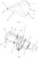
- the headlight module further includes a light adjusting mechanism, and the light adjusting mechanism includes a first ball-headed screw, a second ball-headed screw, a third ball-headed screw, a fixing frame and ball-headed nuts corresponding to the ball-headed screws; the fixing frame and the radiator are connected through the ball-headed screws, wherein the line of centers of ball heads of the first ball-headed screw and the second ball-headed screw extends in a left-right direction, and the line of centers of ball heads of the second ball-headed screw and the third ball-headed screw extends in an up-down direction.
- the present disclosure provides a vehicle headlight which includes the headlight module according to any one of the technical solutions in the second aspect, and the headlight module is arranged longitudinally or horizontally or obliquely.
- the present disclosure provides a vehicle including the vehicle headlight according to any one of the technical solutions in the third aspect.
- the size is small.
- the headlight optical element only the corresponding light sources are required to output the required light pattern, optical elements at various levels required in traditional technical solutions are integrated, and thus the size is small;
- mounting is simple. In addition to the light sources, there is only one headlight optical element. During mounting, it is only necessary to ensure the position precision between the headlight optical element and the light sources, a complicated optical system does not need to be adjusted, and thus the mounting process is simple;
- the optical system has high precision. Only one headlight optical element needs to be arranged, separated primary optical element and lens do not need to be arranged, the structure of the headlight optical element is not complicated, the manufacturing precision of the headlight optical element is easy to guarantee. In the case that the manufacturing precision of the headlight optical element meets the requirement, during assembly, only the relative position precision of one optical element and the light sources needs to be ensured, and the relative position precision between a plurality of optical elements and the light sources does not need to be met, so that the optical system has high precision;
- stray light is greatly eliminated.
- arranging extinction coatings around the light transmitting portion or by arranging the peripheral side surfaces of the light transmitting portion as a low-reflectivity structure with a quite low reflectivity, arranging light shielding members, and meanwhile, arranging the peripheral side surfaces of the light emergent portion as total reflection surfaces light rays cannot be emitted from the side surfaces of the headlight optical element, meanwhile, only a small part of light rays is emitted after being reflected by the side surfaces, the stray light is basically eliminated, and the quality of the light pattern is ensured.
- FIG. 1 is one of structural schematic diagrams of an embodiment of a headlight optical element according to the present disclosure
- FIG. 2 is a structural schematic diagram of light incident surfaces and light emergent surfaces of an embodiment of a headlight optical element according to the present disclosure
- FIG. 3 is a second structural schematic diagram of an embodiment of a headlight optical element according to the present disclosure.
- FIG. 4 is a transverse sectional view of an embodiment of a headlight optical element according to the present disclosure and a schematic diagram of a light path of an embodiment of a headlight optical element according to the present disclosure;
- FIG. 5 is a longitudinal sectional view of an embodiment of a headlight optical element according to the present disclosure and a schematic diagram of a light path of an embodiment of a headlight optical element according to the present disclosure;
- FIG. 6 is an exploded structural schematic view of an embodiment of a headlight module according to the present disclosure.
- FIG. 7 is a structural schematic diagram of an embodiment of a headlight module according to the present disclosure.
- FIG. 8 is a structural schematic diagram of another embodiment of a headlight module according to the present disclosure.
- FIG. 9 is a transverse sectional view of an embodiment of a headlight module according to the present disclosure.
- FIG. 10 is a longitudinal sectional view of an embodiment of a headlight module according to the present disclosure.
- FIG. 11 is a structural schematic diagram of another embodiment of a headlight module according to the present disclosure.
- FIG. 12 is a structural schematic diagram of another embodiment of a headlight optical element according to the present disclosure.
- connection should be understood in a broad sense, unless it is specifically stated and defined otherwise, for example, the connection may mean fixed connection or detachable connection or integral connection; the connection may mean direct connection or indirect connection through an intermediate medium; and the connection may mean internal connection of two elements or interaction between two elements.
- connection may mean fixed connection or detachable connection or integral connection; the connection may mean direct connection or indirect connection through an intermediate medium; and the connection may mean internal connection of two elements or interaction between two elements.
- front indicates the end where a light emergent portion is located
- rear refers to the end where a light incident portion is located
- left refers to the left side in the light emergent direction
- right refers to the right side in the light emergent direction
- up refers to the up side in the light emergent direction
- down refers to the lower side in the light emergent direction.
- a headlight optical element in the basic technical solutions of the present disclosure includes a light incident portion 11 , a light transmitting portion 12 and a light emergent portion 13 which are connected in sequence.
- the light incident portion 11 includes a plurality of light incident surfaces 14 connected in sequence in the left-right direction.
- the light incident surfaces 14 are curved surfaces protruding backwards.
- Light emergent surfaces 15 are curved surfaces protruding forwards.
- a focal point of each light incident surface 14 protruding backwards in the optical axis direction corresponds to a light source 2 .
- Light rays enter the light emergent portion 13 through the light transmitting portion 12 after being collected by the light incident portion 11 , and then are projected forwards through the light emergent portion 13 .
- the light emergent portion 13 can be arranged as a latticed structure for facilitating light adjusting.
- the latticed structure is formed by connecting a plurality of protruding curved surfaces, and a light diffusion direction can be controlled by adjusting the sizes of lattices. Generally, the larger the area of a single lattice, the more obvious the light diffusion.
- the proper lattice area can be chosen according to actual needs for processing, the uniformity of the emergent light pattern is improved, and dispersion is weakened.
- a contour of a front end surface of the light transmitting portion 12 is located within a contour of a rear end portion of the light emergent portion 13 , so that a mounting surface 16 can be formed on a rear end surface of the light emergent portion 13 .
- the mounting surface 16 can be matched with a mounting bracket 3 , thus, the appearance of the headlight module is more beautiful, and mounting is more convenient, in addition, a part of the light rays can be prevented from being emitted to the peripheral side surfaces of the light emergent portion 13 , so that the situation that the part of light rays is emitted from the peripheral side surfaces of the light emergent portion 13 or reflected to the light emergent surfaces 15 of the light emergent portion 13 through the peripheral side surfaces of the light emergent portion 13 to form stray light is avoided.
- a left side surface and a right side surface of the light transmitting portion 12 extend forwards in the optical axis direction and then get closer to the optical axis direction so as to form a low-reflectivity structure.
- part of light rays is usually emitted directly from the side surfaces of the headlight optical element 1 or reflected by the side surfaces and then refracted by the light emergent surfaces 15 of the light emergent portion 13 to form lots of stray light, and consequently the optical performance of the headlight light pattern is affected.
- the light transmitting portion 12 is configured as the above low-reflectivity structure, and incident angles of light rays incident to the left side surface and the right side surface of the light transmitting portion 12 are small, so that the reflectivity of the left side surface and the right side surface of the light transmitting portion 12 is quite low.
- the possibility that the stray light is formed by the light rays which are emitted to the left side surface and the right side surface of the light transmitting portion 12 are reflected to the light emergent surfaces 15 of the light emergent portion 13 is effectively reduced.
- heights of longitudinal sections of an upper side surface and a lower side surface of the light transmitting portion 12 in the optical axis direction are gradually increased to form a triangular-like structure. Since the light incident surfaces 14 of the light incident portion 11 are connected in a row in the left-right direction, the size of the rear end of the headlight optical element 1 in the up-down direction can be smaller, the material cost is reduced, and further the size of the headlight optical element 1 is further reduced.
- no light is emitted to the upper side surface and the lower side surface of the light transmitting portion 12 substantially, and therefore stray light reflected from the upper side surface and the lower side surface of the light transmitting portion 12 to the light emergent surfaces 15 of the light emergent portion 13 scarcely exists.
- the structure of the above light transmitting portion 12 can block part of light rays emitted to the peripheral side surfaces of the light emergent portion 13 , so that light rays emitted to the peripheral side surfaces of the light emergent portion 13 can be totally reflected. Further, the peripheral side surfaces of the light emergent portion 13 get closer to the optical axis direction from back to front so as to totally reflect the light rays totally reflected by the peripheral side surfaces to the opposite side surfaces of the light emergent portion 13 through the light emergent surfaces 15 of the light emergent portion 13 and finally totally reflect the light rays to the side surfaces of the light transmitting portion 12 . As shown in FIG.
- the light transmitting portion 12 with the above longitudinal sections emits most of light rays of light sources 2 directly through the light emergent surfaces 15 of the light emergent portion 13 , and a small part of light rays is emitted to the side surfaces of the light emergent portion 13 .
- the upper (lower) side surface of the light emergent portion 13 is arranged obliquely, so that the light rays totally reflected to the light emergent surfaces 15 through the upper (lower) surface of the light emergent portion 13 can be totally reflected to the lower (upper) side surface of the light emergent portion 13 , and then be totally reflected to the upper (lower) side surface of the light transmitting portion 12 through the lower (upper) side surface of the light emergent portion 13 , and since the incident angle is small, basically no light ray is reflected by the light emergent portion 13 to the light emergent surfaces 15 to avoid forming the stray light. As shown in FIG.
- the side surfaces of the above light transmitting portion 12 are unnecessarily arranged as a low-reflectivity structure, only extinction coatings need to be arranged on the peripheral side surfaces of the light transmitting portion 12 , and reflection and transmission of light rays from the side surfaces of the light transmitting portion 12 can be reduced through the extinction coatings.
- the extinction coatings can be coated with matte black paint, or surfaces of the extinction coatings can be provided with leather grains and coated with ordinary black paint.
- the light transmitting portion 12 is not limited to the above structure.
- the light transmitting portion 12 can also be arranged in a rectangular or cylindrical shape.
- the above triangle-like structure, the low-reflectivity structure and common geometric structures such as a rectangle and a cylinder are optionally combined, and the extinction coatings or the light shielding members are arranged on the surfaces of the light transmitting portion 12 for eliminating the stray light.
- the headlight optical element 1 is integrally formed and may be made of transparent plastic, silica gel or glass.
- the plastic may be PMMA or PC.
- the light incident portion 11 , the light transmitting portion 12 and the light emergent portion 13 of the headlight optical element 1 provided by the present disclosure are simple in structure and can meet the technical requirement of integral forming.
- the headlight optical element 1 is integrally formed, the relative position precision of the light incident portion 11 and the light emergent portion 13 is ensured, the mounting structure and the mounting process are simplified, and the manufacturing cost is reduced.
- the headlight optical element 1 in a preferred embodiment of the present disclosure is integrally formed, and includes a light incident portion 11 , a light transmitting portion 12 and a light emergent portion 13 which are connected in sequence.
- the light incident portion 11 includes a plurality of light incident surfaces 14 sequentially connected in the left-right direction.
- the light incident surfaces 14 are curved surfaces protruding backwards, and light emergent surfaces 15 are curved surfaces protruding forwards, wherein the light emergent surfaces 15 of the light emergent portion 13 can be arranged as a latticed structure for facilitating light adjusting.
- the contour of the front end surface of the light transmitting portion 12 is located within the contour of the rear end portion of the light emergent portion 13 , so that a mounting surface 16 can be formed on the rear end surface of the light emergent portion 13 .
- the mounting surface 16 is matched with a bracket 3 of a headlight module.
- the left side surface and the right side surface of the light transmitting portion 12 extend forwards in the optical axis direction, and then get closer to the optical axis direction, so as to a low-reflectivity structure.
- the heights of the longitudinal sections of the upper side surface and the lower side surface of the light transmitting portion 12 in the optical axis direction are gradually increased, so as to form a triangle-like structure, and light shielding members are arranged on the peripheral side surfaces of the light transmitting portion 12 so as to prevent light rays from being emitted from the side surfaces of the light transmitting portion 12 to the outside.
- the structures of the light incident portion 11 , the light transmitting portion 12 and the light emergent portion 13 of the headlight optical element 1 are relatively simple, so that the headlight optical element 1 can be integrally formed possibly.
- the headlight optical element 1 is quite simple in structure, can be applied to matrix headlights like the above headlight optical elements, is matched with a control system and other headlight components for achieving the ADB function, and meanwhile, has the advantages of small size, low cost, convenient mounting and accurate light pattern.
- a headlight module disclosed by the present disclosure includes a bracket 3 , a circuit board 4 provided with light sources 2 , and a radiator 5 , and further includes the headlight optical element 1 according to any one of the above technical solutions.
- a light transmitting portion 12 of the headlight optical element 1 is arranged in an accommodating cavity formed by the bracket 3 .
- One end of the bracket 3 is fixedly connected with the circuit board 4 and the radiator 5 in sequence, and the other end of the bracket 3 is connected with a mounting surface 16 of a light emergent portion 13 .
- the light sources 2 correspond to focal points of light incident surfaces protruding backwards. Each light source 2 can be independently turned on and off, wherein LED light sources may be used as the light sources 2 .
- One end of the bracket 3 is fixedly connected with the circuit board 4 and the radiator 5 in sequence through threaded connecting members 8 .
- positioning pins 7 are further arranged on the mounting bracket 3 , and correspondingly, the circuit board 4 and the radiator 5 are provided with positioning holes matched with the positioning pins 7 .
- the other end of the bracket 3 can be fixed to the mounting surface 16 through silica gel.
- the headlight module has a simple structure and fewer mounting parts. During the mounting process, only the positions of the light sources 2 relative to the headlight optical element 1 need to be ensured, so that the light adjusting difficulty is low.
- the bracket 3 is of an integrated structure or a detachable structure so as to form the accommodating cavity for accommodating the light transmitting portion 12 .
- the bracket 3 can be matched with the above headlight optical element 1 in structure. If the light transmitting portion 12 of the headlight optical element 1 is of a rectangular or cylindrical structure and other structures, the bracket 3 may be of an integrated structure and can sleeve the light transmitting portion; if the light transmitting portion 12 of the headlight optical element 1 cannot be directly sleeved easily due to the structure, the bracket 3 may be of a detachable structure, as shown in FIG.
- the accommodating cavity of the bracket 3 and the light transmitting portion 12 are matched in shape, the bracket 3 wraps the light transmitting portion 12 after being assembled, and then the detachable bracket 3 is fixed through the threaded connecting members 8 for stably supporting the headlight optical element 1 .
- the bracket 3 can play the role of light shielding members, and the cost for arranging extinction coatings is saved through the bracket 3 made of a lighttight material.
- the above bracket 3 and the headlight optical element 1 can be made into a one-piece member so as to reduce the number of parts and facilitate assembly.
- the one-piece member can be formed by bicolor injection molding.
- An outer side part of the bracket 3 is made of a light-absorbing material. The part of the bracket 3 can prevent light rays incident to the surfaces of the bracket 3 from being emitted out from the side surface, and meanwhile, through the headlight optical element 1 with the low-reflectivity side surfaces, stray light which is reflected by the side surfaces of the light transmitting portion 12 and then emitted out by the light emergent surfaces 15 of the light emergent portion 13 can be greatly reduced, wherein a black PC material may be used as a light-absorbing part material.
- the headlight module further includes a light adjusting mechanism 6 .
- the light adjusting mechanism 6 includes a first ball-headed screw 61 , a second ball-headed screw 62 , a third ball-headed screw 63 , a fixing frame 65 and ball-headed nuts 64 corresponding to the ball-headed screws respectively; the fixing frame 65 and the radiator 5 are connected through the ball-headed screws, wherein the line of centers of ball heads of the first ball-headed screw 61 and the second ball-headed screw 62 extends in the left-right direction, and the line of centers of ball heads of the second ball-headed screw 62 and the third ball-headed screw 63 extends in the up-down direction.
- the light adjusting principle is as follows: by rotating the third ball-headed screw 63 , the third ball-headed screw 63 can move back and forth, at this time, the first ball-headed screw 61 and the second ball-headed screw 62 are fixed, and the above headlight module can rotate with the line of centers of ball heads of the first ball-headed screw 61 and the second ball-headed screw 62 as the axis, so that up-down light adjusting is achieved; by rotating the first ball-headed screw 61 , the first ball-headed screw 61 can move back and forth, at this time, the second ball-headed screw 62 and the third ball-headed screw 63 are fixed, and the above headlight module can rotate with the line of centers of ball heads of the second ball-headed screw 62 and the third ball-headed screw 63 as the axis, so that left-right light adjusting is achieved. Through the light adjusting mechanism 6 , the light adjusting difficulty of the headlight module is further lowered.
- a headlight module in a preferred embodiment of the present disclosure includes a bracket 3 , a circuit board 4 provided with light sources 2 , a radiator 5 , and the headlight optical element 1 according to any one of the above technical solutions.
- the detachable separated type bracket 3 is fixed through screws after tightly wrapping a light transmitting portion 12 of the headlight optical element 1 .
- Positioning pins 7 on the bracket 3 are inserted into positioning holes in the circuit board 4 and the radiator 5 for preliminary positioning.
- One end of the bracket 3 is fixedly connected with the circuit board 4 and the radiator 5 in sequence through threaded connecting members 8 , and the other end of the bracket 3 is connected with a mounting surface 15 of the headlight optical element 1 through silica gel.
- the headlight module further includes a light adjusting mechanism 6 .
- One ends of three ball-headed screws are mounted on the radiator 5 through ball-headed nuts 64 , and the other ends of the three ball-headed screws are connected with a fixing frame 65 .
- the light adjusting function is achieved by adjusting the ball-headed screws.
- the headlight module has fewer parts, and is high in compaction, high in integration degree and small in overall volume; as only the relative position relation of the headlight optical element 1 and the light sources 2 needs to be ensured, mounting is more convenient; as only one headlight optical element 1 needs to be arranged, the structure of the headlight optical element 1 is not complicated, and the manufacturing precision of the headlight optical element 1 is easy to guarantee, an optical system has high precision; and as the headlight module has simple parts and structure, as well as small part number, so that the manufacturing cost is low.
- a vehicle headlight disclosed by the present disclosure includes the headlight module according to any one of the above technical solutions.
- the headlight module is arranged longitudinally or horizontally or obliquely so as to meet different headlight modeling requirements.
- the on-board system automatically and individually controls LED light sources in the headlight module to be turned on and off, a high beam lighting area is subdivided into a plurality of lighting areas, and when the on-board sensor system detects oncoming vehicles on an opposite lane of a road, the LED light sources in the corresponding areas are turned off, so that dazzling caused by high beams is effectively prevented, and a good lighting effect on other areas of the road is achieved.
- the bracket 3 of the headlight module is only arranged around the light transmitting portion 12 , only the light emergent portion 13 is exposed, and the transparency and attractiveness of the exposed portion of the headlight are ensured.
- a vehicle disclosed by the present disclosure includes the vehicle headlight according to any one of the above technical solutions, and adopts the technical solutions of the above embodiments, and therefore the vehicle has at least the beneficial effects achieved by the technical solutions of the above embodiments.
Landscapes
- Engineering & Computer Science (AREA)
- General Engineering & Computer Science (AREA)
- Physics & Mathematics (AREA)
- Microelectronics & Electronic Packaging (AREA)
- Optics & Photonics (AREA)
- Mechanical Engineering (AREA)
- Mathematical Physics (AREA)
- Non-Portable Lighting Devices Or Systems Thereof (AREA)
- Lighting Device Outwards From Vehicle And Optical Signal (AREA)
- Planar Illumination Modules (AREA)
Abstract
The present disclosure relates to vehicle lighting devices, and discloses a headlight optical element. The headlight optical element includes a light incident portion, a light transmitting portion and a light emergent portion which are connected in sequence, wherein the light incident portion includes a plurality of light incident surfaces connected sequentially in a left-right direction; the light incident surfaces are curved surfaces protruding backwards in the optical axis direction; and light emergent surfaces are curved surfaces protruding forwards in the optical axis direction. In addition, the present disclosure further discloses a headlight module, a vehicle headlight and a vehicle. The headlight optical element provided by the present disclosure is small in size, high in optical precision, accurate in light pattern, convenient to mount and low in cost.
Description
This application is a 35 USC § 371 national stage of international application No. PCT/CN2019/105936, which was filed Sep. 16, 2019, claims priority to Chinese Application No. 201910488336.X, filed on Jun. 5, 2019; Chinese Application No. 201920859938.7, filed on Jun. 5, 2019; Chinese Application No. 201910730411.9, filed on Aug. 8, 2019; and Chinese Application No. 201910780214.8, filed on Aug. 22, 2019, and is entitled “HEADLIGHT OPTICAL ELEMENT, HEADLIGHT MODULE, VEHICLE HEADLIGHT AND VEHICLE,” all of which are incorporated herein by reference as if fully set forth.
The present disclosure relates to vehicle lighting devices, in particular to a headlight optical element, and also relates to a headlight module, a vehicle headlight and a vehicle.
For driving at night, the importance of vehicle lighting systems, especially headlights, is self-evident. When vehicles are running at a high speed, drivers may lose control of the vehicles due to dazzling high beams, and consequently unpredictable danger occurs. Vehicle headlights need to not only provide the drivers with a wide range of vision and good visual conditions, but also affect other road participants as little as possible without dazzling other road participants. With the development of technologies, matrix LED headlights have become one of future development trends for the vehicle headlights. Light sources of matrix LED high beams are composed of a plurality of LEDs which are arranged in an array pattern according to certain modes. Depending on positions of the vehicles and pedestrians in the field of vision in front of the vehicles, LEDs in the corresponding areas of the matrix LED headlights can be turned off, and thus dazzling of pedestrians or oncoming drivers is avoided.
In the prior art, a general matrix headlight module is provided with various optical elements. In order to ensure a light utilization rate and control a light pattern, all the optical elements are usually complicated in structure design and cannot be integrally formed easily, and the optical elements can only be processed and mounted separately, so that the problems of complicated mounting, large sizes of headlights and high manufacturing cost are caused. The Chinese patent for invention with the application number being CN109611780A discloses a motor vehicle high beam lighting module, wherein a condenser is a primary optical element of the module, a lens is a secondary optical element of the module, and the above condenser is composed of a plurality of collimation units, an emergent path of light is controlled through the collimation units, and therefore, the structure of the condenser is complicated, and separate production is reasonable. The Chinese patent for invention with the application number being CN109357235A discloses a matrix headlight system based on inverted LED white light chips. Each inverted LED white light chip is provided with a reflector correspondingly; a light guide column is arranged above each inverted LED white light chip correspondingly; light rays emitted by the corresponding inverted LED white light chips are gathered by the reflectors; and after the light rays are shaped by the corresponding light guide columns, rectangular light spots can be formed and then emitted through the lens. The reflectors, the light guide columns and the lens are matched with each other. Although the structures of the reflectors, the light guide columns and the lens are simple, the reflectors, the light guide columns and the lens cannot be integrally formed easily, and still need to be mounted separately.
Due to the fact that corresponding mounting brackets need to be arranged for separately mounting the optical elements, the structure of a headlight module is complicated, and the size of the headlight module is increased while the cost of the headlight module is increased. In the above Chinese patent for invention with the application number being CN109611780A, the mounting structure and mounting process of the headlight module are specifically described. Since the relative position precision between the various optical elements needs to be ensured so as to ensure the optical performance of the headlight, the manufacturing precision of the optical elements and the positioning and mounting precision of the headlight module are quite high. Therefore, special mounting structures such as mounting grooves and positioning grooves and special components for mounting the various optical elements, such as positioning columns, pressure plates and mounting brackets are needed, and the manufacturing cost is increased.
As mentioned above, in order to pursue a precise light pattern and diversified light pattern superposition modes, matrix headlights are often large and expensive. However, the matrix headlights are required to achieve an ADB function, the structures of the headlights need to be further simplified and the cost of the headlights needs to be reduced on the basis of the ADB function, and therefore, the price of the matrix headlights is more acceptable to the public.
In view of the above defects of the prior art, it is necessary to design a novel headlight optical element.
The first technical problem needing to be solved by the present disclosure is to provide a headlight optical element. The headlight optical element is not only small in size, but also high in optical precision, accurate in light pattern, convenient to mount and low in cost.
The second technical problem needing to be solved by the present disclosure is to provide a headlight module. The headlight module is not only small in size, but also high in optical precision, accurate in light pattern, simple in light adjusting, few in components, easy to mount and low in manufacturing cost and processing cost.
The third technical problem needing to be solved by the present disclosure is to provide a vehicle headlight. The vehicle headlight is small in size, high in optical precision, accurate in light pattern, simple in light adjusting, few in components, easy to mount, low in manufacturing cost and processing cost and diversified in light pattern superposition modes.
The fourth technical problem needing to be solved by the present disclosure is to provide a vehicle. The vehicle is small in vehicle headlight size, high in optical precision, accurate in light pattern, simple in light adjusting, few in components, easy to mount and low in manufacturing cost and processing cost.
In order to achieve the above objects, in the first aspect, the present disclosure provides a headlight optical element which includes a light incident portion, a light transmitting portion and a light emergent portion which are connected in sequence. The light incident portion includes a plurality of light incident surfaces connected in sequence in a left-right direction. The light incident surfaces are curved surfaces protruding backwards. Light emergent surfaces are curved surfaces protruding forwards.
Preferably, a contour of a front end surface of the light transmitting portion is located within a contour of a rear end portion of the light emergent portion, and thus a mounting surface can be formed on a rear end surface of the light emergent portion.
Preferably, a left side surface and a right side surface of the light transmitting portion extend forwards in an optical axis direction and then get closer to the optical axis direction.
As a preferred structural form of the present disclosure, heights of longitudinal sections of an upper side surface and a lower side surface of the light transmitting portion in the optical axis direction are gradually increased.
As a preferred structural form of the present disclosure, side surfaces of four sides of the light emergent portion get closer to the optical axis direction from back to front, and therefore light rays can be completely reflected to side surfaces of the light transmitting portion.
Preferably, extinction coatings or light shielding members are arranged on a surface of the light transmitting portion.
Specifically, the headlight optical element is integrally formed.
In the second aspect, the present disclosure provides a headlight module which includes a bracket, a circuit board provided with light sources, and a radiator, and further includes the headlight optical element according to any one of the technical solutions in the first aspect. The light transmitting portion of the headlight optical element is arranged in an accommodating cavity formed by the bracket, one end of the bracket is fixedly connected with the circuit board and the radiator sequentially, and the other end of the bracket is connected with the mounting surface of the light emergent portion.
Preferably, the bracket is of an integrated structure or a detachable structure so as to form the accommodating cavity for accommodating the light transmitting portion.
As a specific structural form, the headlight module further includes a light adjusting mechanism, and the light adjusting mechanism includes a first ball-headed screw, a second ball-headed screw, a third ball-headed screw, a fixing frame and ball-headed nuts corresponding to the ball-headed screws; the fixing frame and the radiator are connected through the ball-headed screws, wherein the line of centers of ball heads of the first ball-headed screw and the second ball-headed screw extends in a left-right direction, and the line of centers of ball heads of the second ball-headed screw and the third ball-headed screw extends in an up-down direction.
In the third aspect, the present disclosure provides a vehicle headlight which includes the headlight module according to any one of the technical solutions in the second aspect, and the headlight module is arranged longitudinally or horizontally or obliquely.
In the fourth aspect, the present disclosure provides a vehicle including the vehicle headlight according to any one of the technical solutions in the third aspect.
Through the basic technical solutions of the present disclosure, embodiments have the following beneficial effects:
1. the size is small. As the headlight optical element, only the corresponding light sources are required to output the required light pattern, optical elements at various levels required in traditional technical solutions are integrated, and thus the size is small;
2. mounting is simple. In addition to the light sources, there is only one headlight optical element. During mounting, it is only necessary to ensure the position precision between the headlight optical element and the light sources, a complicated optical system does not need to be adjusted, and thus the mounting process is simple;
3. the optical system has high precision. Only one headlight optical element needs to be arranged, separated primary optical element and lens do not need to be arranged, the structure of the headlight optical element is not complicated, the manufacturing precision of the headlight optical element is easy to guarantee. In the case that the manufacturing precision of the headlight optical element meets the requirement, during assembly, only the relative position precision of one optical element and the light sources needs to be ensured, and the relative position precision between a plurality of optical elements and the light sources does not need to be met, so that the optical system has high precision;
4. light adjusting difficulty is low. Only the relative position precision between one headlight optical element and the light sources needs to be ensured, compared with complicated optical systems which require much light adjusting design in the prior art, the optical system is low in light adjusting difficulty;
5. the costs are low. The structure is simple, the number of parts is small, and thus the manufacturing cost and the processing cost are low.
In addition, in preferred embodiments of the present disclosure, stray light is greatly eliminated. By arranging extinction coatings around the light transmitting portion or by arranging the peripheral side surfaces of the light transmitting portion as a low-reflectivity structure with a quite low reflectivity, arranging light shielding members, and meanwhile, arranging the peripheral side surfaces of the light emergent portion as total reflection surfaces, light rays cannot be emitted from the side surfaces of the headlight optical element, meanwhile, only a small part of light rays is emitted after being reflected by the side surfaces, the stray light is basically eliminated, and the quality of the light pattern is ensured.
The other advantages of the present disclosure and the technical effects of the preferred embodiments will be further described in the following specific embodiments.
- 1. Headlight optical element
- 12. Light transmitting portion
- 14. Light incident surfaces
- 16. Mounting surface
- 2. Light sources
- 4. Circuit board
- 6. Light adjusting mechanism
- 62. Second ball-headed screw
- 64. Ball-headed nuts
- 7. Positioning pins
- 11. Light incident portion
- 13. Light emergent portion
- 15. Light emergent surfaces
- 3. Bracket
- 5. Radiator
- 61. First ball-headed screw
- 63. Third ball-headed screw
- 65. Fixing frame
- 8. Threaded connecting members
Hereunder the embodiments of the present disclosure will be described in detail, with reference to the accompanying drawings. It should be appreciated that the embodiments described here are only provided to describe and explain the present disclosure, but shall not be deemed as constituting any limitation to the present disclosure.
It should be noted that in the description of the present disclosure, the term “connection” should be understood in a broad sense, unless it is specifically stated and defined otherwise, for example, the connection may mean fixed connection or detachable connection or integral connection; the connection may mean direct connection or indirect connection through an intermediate medium; and the connection may mean internal connection of two elements or interaction between two elements. For ordinary those skilled in the art, the specific meanings of the above term in the present disclosure can be understood according to specific situations.
It should be understood that in the light emergent direction, “front” indicates the end where a light emergent portion is located, “rear” refers to the end where a light incident portion is located, “left” refers to the left side in the light emergent direction, and “right” refers to the right side in the light emergent direction, “up” refers to the up side in the light emergent direction, and “down” refers to the lower side in the light emergent direction. The terms are based on the orientation or position relationship shown in the drawings, and are only for the convenience of describing the present disclosure and simplifying the description, rather than indicating or implying that the device or element referred to may have a specific orientation, construction and operation in a specific orientation, and therefore the terms should not be construed as a limitation on the present disclosure.
Referring to FIGS. 1-3 , a headlight optical element in the basic technical solutions of the present disclosure includes a light incident portion 11, a light transmitting portion 12 and a light emergent portion 13 which are connected in sequence. The light incident portion 11 includes a plurality of light incident surfaces 14 connected in sequence in the left-right direction. The light incident surfaces 14 are curved surfaces protruding backwards. Light emergent surfaces 15 are curved surfaces protruding forwards.
In the above basic solutions, a focal point of each light incident surface 14 protruding backwards in the optical axis direction corresponds to a light source 2. Light rays enter the light emergent portion 13 through the light transmitting portion 12 after being collected by the light incident portion 11, and then are projected forwards through the light emergent portion 13. The light emergent portion 13 can be arranged as a latticed structure for facilitating light adjusting. The latticed structure is formed by connecting a plurality of protruding curved surfaces, and a light diffusion direction can be controlled by adjusting the sizes of lattices. Generally, the larger the area of a single lattice, the more obvious the light diffusion. The proper lattice area can be chosen according to actual needs for processing, the uniformity of the emergent light pattern is improved, and dispersion is weakened.
Preferably, a contour of a front end surface of the light transmitting portion 12 is located within a contour of a rear end portion of the light emergent portion 13, so that a mounting surface 16 can be formed on a rear end surface of the light emergent portion 13. Referring to FIG. 3 , FIG. 6 and FIG. 7 , when the headlight optical element 1 is mounted inside a headlight module, the mounting surface 16 can be matched with a mounting bracket 3, thus, the appearance of the headlight module is more beautiful, and mounting is more convenient, in addition, a part of the light rays can be prevented from being emitted to the peripheral side surfaces of the light emergent portion 13, so that the situation that the part of light rays is emitted from the peripheral side surfaces of the light emergent portion 13 or reflected to the light emergent surfaces 15 of the light emergent portion 13 through the peripheral side surfaces of the light emergent portion 13 to form stray light is avoided.
As a preferred structural form, referring to FIG. 4 , a left side surface and a right side surface of the light transmitting portion 12 extend forwards in the optical axis direction and then get closer to the optical axis direction so as to form a low-reflectivity structure. In the light transmission process, part of light rays is usually emitted directly from the side surfaces of the headlight optical element 1 or reflected by the side surfaces and then refracted by the light emergent surfaces 15 of the light emergent portion 13 to form lots of stray light, and consequently the optical performance of the headlight light pattern is affected. According to the present disclosure, the light transmitting portion 12 is configured as the above low-reflectivity structure, and incident angles of light rays incident to the left side surface and the right side surface of the light transmitting portion 12 are small, so that the reflectivity of the left side surface and the right side surface of the light transmitting portion 12 is quite low. The possibility that the stray light is formed by the light rays which are emitted to the left side surface and the right side surface of the light transmitting portion 12 are reflected to the light emergent surfaces 15 of the light emergent portion 13 is effectively reduced.
As another preferred structural form, referring to FIG. 5 , heights of longitudinal sections of an upper side surface and a lower side surface of the light transmitting portion 12 in the optical axis direction are gradually increased to form a triangular-like structure. Since the light incident surfaces 14 of the light incident portion 11 are connected in a row in the left-right direction, the size of the rear end of the headlight optical element 1 in the up-down direction can be smaller, the material cost is reduced, and further the size of the headlight optical element 1 is further reduced. In the preferred structure, no light is emitted to the upper side surface and the lower side surface of the light transmitting portion 12 substantially, and therefore stray light reflected from the upper side surface and the lower side surface of the light transmitting portion 12 to the light emergent surfaces 15 of the light emergent portion 13 scarcely exists.
The structure of the above light transmitting portion 12 can block part of light rays emitted to the peripheral side surfaces of the light emergent portion 13, so that light rays emitted to the peripheral side surfaces of the light emergent portion 13 can be totally reflected. Further, the peripheral side surfaces of the light emergent portion 13 get closer to the optical axis direction from back to front so as to totally reflect the light rays totally reflected by the peripheral side surfaces to the opposite side surfaces of the light emergent portion 13 through the light emergent surfaces 15 of the light emergent portion 13 and finally totally reflect the light rays to the side surfaces of the light transmitting portion 12. As shown in FIG. 5 , the light transmitting portion 12 with the above longitudinal sections emits most of light rays of light sources 2 directly through the light emergent surfaces 15 of the light emergent portion 13, and a small part of light rays is emitted to the side surfaces of the light emergent portion 13. The upper (lower) side surface of the light emergent portion 13 is arranged obliquely, so that the light rays totally reflected to the light emergent surfaces 15 through the upper (lower) surface of the light emergent portion 13 can be totally reflected to the lower (upper) side surface of the light emergent portion 13, and then be totally reflected to the upper (lower) side surface of the light transmitting portion 12 through the lower (upper) side surface of the light emergent portion 13, and since the incident angle is small, basically no light ray is reflected by the light emergent portion 13 to the light emergent surfaces 15 to avoid forming the stray light. As shown in FIG. 4 , through the light transmitting portion 12 with the above transverse section, most of light rays of light sources 2 is directly emitted by the light emergent surfaces 15 of the light emergent portion 13, and a part of the light rays is emitted to the side surfaces of the light emergent portion 12, incident angles of light rays incident to the left side surface and right side surface of the light transmitting portion 12 are small, so that the side surface reflectivity is quite low, and the light rays emitted to the left side surface and the right side surface of the light transmitting portion 12 cannot be reflected into the light emergent portion 13; a part of light rays is emitted to the side surfaces of the light emergent portion 13, the left (right) side surface of the light emergent portion 13 is arranged obliquely, thus, the light rays totally reflected by the left (right) surface of the light emergent portion 13 to the light emergent surfaces 15 can be totally reflected to the right (left) side surface of the light emergent portion 13 and then totally reflected by the right (left) side surface of the light emergent portion 13 to the left (right) side surface of the light transmitting portion 12, and since the reflectivity of the left side surface and the right side surface of the light transmitting portion 12 is extremely low, basically no light ray is reflected by the left and right side surfaces of the light transmitting portion 12 to the light emergent surface 15 to avoid forming the stray light.
However, stray light refracted to the outside by the side surfaces of the light transmitting portion 12 cannot be effectively eliminated through the structure, and light shielding members can be arranged on the peripheral side surfaces of the light transmitting portion 12 to prevent light rays from being emitted to the outside. Alternatively, the side surfaces of the above light transmitting portion 12 are unnecessarily arranged as a low-reflectivity structure, only extinction coatings need to be arranged on the peripheral side surfaces of the light transmitting portion 12, and reflection and transmission of light rays from the side surfaces of the light transmitting portion 12 can be reduced through the extinction coatings. The extinction coatings can be coated with matte black paint, or surfaces of the extinction coatings can be provided with leather grains and coated with ordinary black paint.
It should be noted that the light transmitting portion 12 is not limited to the above structure. In order to meet the requirements of the headlight appearance or to further simplify the structure of the headlight optical element 1 for cost reduction, the light transmitting portion 12 can also be arranged in a rectangular or cylindrical shape. Alternatively, the above triangle-like structure, the low-reflectivity structure and common geometric structures such as a rectangle and a cylinder are optionally combined, and the extinction coatings or the light shielding members are arranged on the surfaces of the light transmitting portion 12 for eliminating the stray light.
Preferably, the headlight optical element 1 is integrally formed and may be made of transparent plastic, silica gel or glass. The plastic may be PMMA or PC. The light incident portion 11, the light transmitting portion 12 and the light emergent portion 13 of the headlight optical element 1 provided by the present disclosure are simple in structure and can meet the technical requirement of integral forming. The headlight optical element 1 is integrally formed, the relative position precision of the light incident portion 11 and the light emergent portion 13 is ensured, the mounting structure and the mounting process are simplified, and the manufacturing cost is reduced.
Referring to FIGS. 1-5 , the headlight optical element 1 in a preferred embodiment of the present disclosure is integrally formed, and includes a light incident portion 11, a light transmitting portion 12 and a light emergent portion 13 which are connected in sequence. The light incident portion 11 includes a plurality of light incident surfaces 14 sequentially connected in the left-right direction. The light incident surfaces 14 are curved surfaces protruding backwards, and light emergent surfaces 15 are curved surfaces protruding forwards, wherein the light emergent surfaces 15 of the light emergent portion 13 can be arranged as a latticed structure for facilitating light adjusting. The contour of the front end surface of the light transmitting portion 12 is located within the contour of the rear end portion of the light emergent portion 13, so that a mounting surface 16 can be formed on the rear end surface of the light emergent portion 13. The mounting surface 16 is matched with a bracket 3 of a headlight module. The left side surface and the right side surface of the light transmitting portion 12 extend forwards in the optical axis direction, and then get closer to the optical axis direction, so as to a low-reflectivity structure. The heights of the longitudinal sections of the upper side surface and the lower side surface of the light transmitting portion 12 in the optical axis direction are gradually increased, so as to form a triangle-like structure, and light shielding members are arranged on the peripheral side surfaces of the light transmitting portion 12 so as to prevent light rays from being emitted from the side surfaces of the light transmitting portion 12 to the outside.
In the preferred embodiment, the structures of the light incident portion 11, the light transmitting portion 12 and the light emergent portion 13 of the headlight optical element 1 are relatively simple, so that the headlight optical element 1 can be integrally formed possibly. Compared with optical elements which adopt matched reflectors and light guide columns or condensers with complicated mounting structures or other modes for obtaining the accurate and clear light pattern in the prior art, the headlight optical element 1 is quite simple in structure, can be applied to matrix headlights like the above headlight optical elements, is matched with a control system and other headlight components for achieving the ADB function, and meanwhile, has the advantages of small size, low cost, convenient mounting and accurate light pattern.
A headlight module disclosed by the present disclosure, referring to FIG. 6 , includes a bracket 3, a circuit board 4 provided with light sources 2, and a radiator 5, and further includes the headlight optical element 1 according to any one of the above technical solutions. A light transmitting portion 12 of the headlight optical element 1 is arranged in an accommodating cavity formed by the bracket 3. One end of the bracket 3 is fixedly connected with the circuit board 4 and the radiator 5 in sequence, and the other end of the bracket 3 is connected with a mounting surface 16 of a light emergent portion 13.
The light sources 2 correspond to focal points of light incident surfaces protruding backwards. Each light source 2 can be independently turned on and off, wherein LED light sources may be used as the light sources 2. One end of the bracket 3 is fixedly connected with the circuit board 4 and the radiator 5 in sequence through threaded connecting members 8. In order to facilitate positioning, positioning pins 7 are further arranged on the mounting bracket 3, and correspondingly, the circuit board 4 and the radiator 5 are provided with positioning holes matched with the positioning pins 7. The other end of the bracket 3 can be fixed to the mounting surface 16 through silica gel. The headlight module has a simple structure and fewer mounting parts. During the mounting process, only the positions of the light sources 2 relative to the headlight optical element 1 need to be ensured, so that the light adjusting difficulty is low.
Specifically, the bracket 3 is of an integrated structure or a detachable structure so as to form the accommodating cavity for accommodating the light transmitting portion 12. The bracket 3 can be matched with the above headlight optical element 1 in structure. If the light transmitting portion 12 of the headlight optical element 1 is of a rectangular or cylindrical structure and other structures, the bracket 3 may be of an integrated structure and can sleeve the light transmitting portion; if the light transmitting portion 12 of the headlight optical element 1 cannot be directly sleeved easily due to the structure, the bracket 3 may be of a detachable structure, as shown in FIG. 8 , the accommodating cavity of the bracket 3 and the light transmitting portion 12 are matched in shape, the bracket 3 wraps the light transmitting portion 12 after being assembled, and then the detachable bracket 3 is fixed through the threaded connecting members 8 for stably supporting the headlight optical element 1. In order to prevent light rays from being emitted around the light transmitting portion 12, the bracket 3 can play the role of light shielding members, and the cost for arranging extinction coatings is saved through the bracket 3 made of a lighttight material. Further, referring to FIGS. 11 and 12 , the above bracket 3 and the headlight optical element 1 can be made into a one-piece member so as to reduce the number of parts and facilitate assembly. In order to achieve the same effect of eliminating stray light, the one-piece member can be formed by bicolor injection molding. An outer side part of the bracket 3 is made of a light-absorbing material. The part of the bracket 3 can prevent light rays incident to the surfaces of the bracket 3 from being emitted out from the side surface, and meanwhile, through the headlight optical element 1 with the low-reflectivity side surfaces, stray light which is reflected by the side surfaces of the light transmitting portion 12 and then emitted out by the light emergent surfaces 15 of the light emergent portion 13 can be greatly reduced, wherein a black PC material may be used as a light-absorbing part material.
The headlight module further includes a light adjusting mechanism 6. The light adjusting mechanism 6 includes a first ball-headed screw 61, a second ball-headed screw 62, a third ball-headed screw 63, a fixing frame 65 and ball-headed nuts 64 corresponding to the ball-headed screws respectively; the fixing frame 65 and the radiator 5 are connected through the ball-headed screws, wherein the line of centers of ball heads of the first ball-headed screw 61 and the second ball-headed screw 62 extends in the left-right direction, and the line of centers of ball heads of the second ball-headed screw 62 and the third ball-headed screw 63 extends in the up-down direction. The light adjusting principle is as follows: by rotating the third ball-headed screw 63, the third ball-headed screw 63 can move back and forth, at this time, the first ball-headed screw 61 and the second ball-headed screw 62 are fixed, and the above headlight module can rotate with the line of centers of ball heads of the first ball-headed screw 61 and the second ball-headed screw 62 as the axis, so that up-down light adjusting is achieved; by rotating the first ball-headed screw 61, the first ball-headed screw 61 can move back and forth, at this time, the second ball-headed screw 62 and the third ball-headed screw 63 are fixed, and the above headlight module can rotate with the line of centers of ball heads of the second ball-headed screw 62 and the third ball-headed screw 63 as the axis, so that left-right light adjusting is achieved. Through the light adjusting mechanism 6, the light adjusting difficulty of the headlight module is further lowered.
Referring to FIGS. 6-10 , a headlight module in a preferred embodiment of the present disclosure includes a bracket 3, a circuit board 4 provided with light sources 2, a radiator 5, and the headlight optical element 1 according to any one of the above technical solutions. The detachable separated type bracket 3 is fixed through screws after tightly wrapping a light transmitting portion 12 of the headlight optical element 1. Positioning pins 7 on the bracket 3 are inserted into positioning holes in the circuit board 4 and the radiator 5 for preliminary positioning. One end of the bracket 3 is fixedly connected with the circuit board 4 and the radiator 5 in sequence through threaded connecting members 8, and the other end of the bracket 3 is connected with a mounting surface 15 of the headlight optical element 1 through silica gel. The headlight module further includes a light adjusting mechanism 6. One ends of three ball-headed screws are mounted on the radiator 5 through ball-headed nuts 64, and the other ends of the three ball-headed screws are connected with a fixing frame 65. The light adjusting function is achieved by adjusting the ball-headed screws. In this way, by virtue of the headlight optical element 1 of the present disclosure, the headlight module has fewer parts, and is high in compaction, high in integration degree and small in overall volume; as only the relative position relation of the headlight optical element 1 and the light sources 2 needs to be ensured, mounting is more convenient; as only one headlight optical element 1 needs to be arranged, the structure of the headlight optical element 1 is not complicated, and the manufacturing precision of the headlight optical element 1 is easy to guarantee, an optical system has high precision; and as the headlight module has simple parts and structure, as well as small part number, so that the manufacturing cost is low.
A vehicle headlight disclosed by the present disclosure includes the headlight module according to any one of the above technical solutions. The headlight module is arranged longitudinally or horizontally or obliquely so as to meet different headlight modeling requirements. In cooperation with an on-board sensor system, the on-board system automatically and individually controls LED light sources in the headlight module to be turned on and off, a high beam lighting area is subdivided into a plurality of lighting areas, and when the on-board sensor system detects oncoming vehicles on an opposite lane of a road, the LED light sources in the corresponding areas are turned off, so that dazzling caused by high beams is effectively prevented, and a good lighting effect on other areas of the road is achieved. Meanwhile, the bracket 3 of the headlight module is only arranged around the light transmitting portion 12, only the light emergent portion 13 is exposed, and the transparency and attractiveness of the exposed portion of the headlight are ensured.
A vehicle disclosed by the present disclosure includes the vehicle headlight according to any one of the above technical solutions, and adopts the technical solutions of the above embodiments, and therefore the vehicle has at least the beneficial effects achieved by the technical solutions of the above embodiments.
While the preferred embodiments of the present disclosure are described above in details with reference to the accompanying drawings, the present disclosure is not limited thereto. Within the scope of the technical conception of the present disclosure, a variety of simple modifications can be made to the technical solutions of the present disclosure, including combinations of specific technical features in any proper manner. In order to avoid unnecessary repetition, various possible combinations are not described separately in the present disclosure. However, the simple modifications and combinations may also be regarded as the content disclosed by the present disclosure, and fall into the protection scope of the present disclosure.
Claims (10)
1. A headlight optical element comprising a light incident portion, a light transmitting portion and a light emergent portion which are connected in sequence, wherein the light incident portion comprises a plurality of light incident surfaces connected sequentially in a left-right direction; the light incident surfaces are curved surfaces protruding backwards; and a light emergent surface of the light emergent portion is a curved surface protruding forwards; a left side surface and a right side surface of the light transmitting portion extend forwards in an optical axis direction and then get closer to the optical axis; and heights of longitudinal sections of an upper side surface and a lower side surface of the light transmitting portion in the optical axis direction are gradually increased.
2. The headlight optical element according to claim 1 , wherein a contour of a front end surface of the light transmitting portion is located in the scope of a contour of a rear end portion of the light emergent portion, so that a mounting surface is formed on a rear end surface of the light emergent portion.
3. The headlight optical element according to claim 1 , wherein peripheral side surfaces of the light emergent portion get closer to an optical axis direction from back to front so as to totally reflect light rays to side surfaces of the light transmitting portion.
4. The headlight optical element according to claim 1 , wherein surfaces of the light transmitting portion are provided with an extinction coating or a light shielding member.
5. The headlight optical element according to claim 1 , wherein the headlight optical element is integrally formed.
6. A headlight module comprising a bracket, a circuit board provided with light sources and a radiator, and further comprising the headlight optical element according to any one of claim 1 , wherein the light transmitting portion of the headlight optical element is arranged in an accommodating cavity formed by the bracket, one end of the bracket is fixedly connected with the circuit board and the radiator in sequence, and the other end of the bracket is connected with a mounting surface of the light emergent portion.
7. The headlight module according to claim 6 , wherein the bracket is of an integrated structure or a detachable structure so as to form an accommodating cavity for accommodating the light transmitting portion.
8. The headlight module according to claim 6 , wherein further comprising a light adjusting mechanism, the light adjusting mechanism comprises a first ball-headed screw, a second ball-headed screw, a third ball-headed screw, a fixing frame and ball-headed nuts corresponding to the ball-headed screws respectively; the fixing frame and the radiator are connected through the ball-headed screws, a line of centers of ball heads of the first ball-headed screw and the second ball-headed screw extends in a left-right direction, and a line of centers of ball heads of the second ball-headed screw and the third ball-headed screw extends in an up-down direction.
9. A vehicle headlight comprising at least one headlight module according to claim 6 , wherein the headlight module is distributed longitudinally or horizontally or obliquely.
10. A vehicle comprising the vehicle headlight according to claim 9 .
Applications Claiming Priority (9)
| Application Number | Priority Date | Filing Date | Title |
|---|---|---|---|
| CN201920859938.7 | 2019-06-05 | ||
| CN201920859938 | 2019-06-05 | ||
| CN201910488336 | 2019-06-05 | ||
| CN201910488336.X | 2019-06-05 | ||
| CN201910730411.9 | 2019-08-08 | ||
| CN201910730411 | 2019-08-08 | ||
| CN201910780214.8 | 2019-08-22 | ||
| CN201910780214.8A CN111503590B (en) | 2019-06-05 | 2019-08-22 | Headlight optical element, headlight module, vehicle headlamp and vehicle |
| PCT/CN2019/105936 WO2020244087A1 (en) | 2019-06-05 | 2019-09-16 | Vehicle lamp optical element, vehicle lamp module, vehicle headlamp, and vehicle |
Publications (2)
| Publication Number | Publication Date |
|---|---|
| US20230160550A1 US20230160550A1 (en) | 2023-05-25 |
| US11708953B2 true US11708953B2 (en) | 2023-07-25 |
Family
ID=69919893
Family Applications (6)
| Application Number | Title | Priority Date | Filing Date |
|---|---|---|---|
| US17/616,678 Active 2040-07-17 US12085246B2 (en) | 2019-06-05 | 2019-09-05 | Vehicle headlamp and vehicle |
| US16/965,178 Active 2041-04-05 US11708953B2 (en) | 2019-06-05 | 2019-09-16 | Headlight optical element, headlight module, vehicle headlight and vehicle |
| US17/046,582 Active 2040-12-31 US11674653B2 (en) | 2019-06-05 | 2019-09-27 | Headlight optical element, headlight module, vehicle headlight and vehicle |
| US17/596,007 Active 2040-03-24 US12013092B2 (en) | 2019-06-05 | 2020-01-08 | Automotive lamp optical element and automotive headlamp |
| US17/596,008 Active 2040-03-03 US11879608B2 (en) | 2019-06-05 | 2020-01-08 | Automotive lamp optical element, automotive lamp module, and vehicle |
| US17/419,595 Active 2040-07-25 US11674654B2 (en) | 2019-06-05 | 2020-04-17 | Vehicle light optical element, vehicle light module, vehicle headlight, and vehicle |
Family Applications Before (1)
| Application Number | Title | Priority Date | Filing Date |
|---|---|---|---|
| US17/616,678 Active 2040-07-17 US12085246B2 (en) | 2019-06-05 | 2019-09-05 | Vehicle headlamp and vehicle |
Family Applications After (4)
| Application Number | Title | Priority Date | Filing Date |
|---|---|---|---|
| US17/046,582 Active 2040-12-31 US11674653B2 (en) | 2019-06-05 | 2019-09-27 | Headlight optical element, headlight module, vehicle headlight and vehicle |
| US17/596,007 Active 2040-03-24 US12013092B2 (en) | 2019-06-05 | 2020-01-08 | Automotive lamp optical element and automotive headlamp |
| US17/596,008 Active 2040-03-03 US11879608B2 (en) | 2019-06-05 | 2020-01-08 | Automotive lamp optical element, automotive lamp module, and vehicle |
| US17/419,595 Active 2040-07-25 US11674654B2 (en) | 2019-06-05 | 2020-04-17 | Vehicle light optical element, vehicle light module, vehicle headlight, and vehicle |
Country Status (6)
| Country | Link |
|---|---|
| US (6) | US12085246B2 (en) |
| EP (2) | EP3982033B1 (en) |
| JP (4) | JP7330272B2 (en) |
| CN (9) | CN112050162A (en) |
| DE (2) | DE112019005799B4 (en) |
| WO (6) | WO2020244079A1 (en) |
Families Citing this family (17)
| Publication number | Priority date | Publication date | Assignee | Title |
|---|---|---|---|---|
| CN210740255U (en) * | 2019-06-05 | 2020-06-12 | 华域视觉科技(上海)有限公司 | Car light optical element, car light module, vehicle headlamp and vehicle |
| CN112050162A (en) * | 2019-06-05 | 2020-12-08 | 华域视觉科技(上海)有限公司 | Car light optical element, car light module and vehicle |
| CN211822197U (en) * | 2020-01-21 | 2020-10-30 | 华域视觉科技(上海)有限公司 | Headlamp module, headlamp and vehicle |
| CN113958921A (en) * | 2020-12-29 | 2022-01-21 | 华域视觉科技(上海)有限公司 | Lighting module, lighting device and vehicle |
| DE112021003257T5 (en) * | 2020-06-16 | 2023-05-04 | Idemitsu Kosan Co., Ltd. | Interior component for vehicle lamp |
| CN112781002B (en) * | 2020-07-17 | 2025-07-25 | 华域视觉科技(上海)有限公司 | Vehicle high beam module, vehicle head lamp and vehicle |
| CN112797368A (en) * | 2020-09-08 | 2021-05-14 | 华域视觉科技(上海)有限公司 | A vehicle headlamp optical system, vehicle headlamp and vehicle |
| CN113266797A (en) * | 2020-11-16 | 2021-08-17 | 华域视觉科技(上海)有限公司 | High-beam and low-beam integrated car lamp optical element, car lamp module, car lamp and car |
| CN214038234U (en) * | 2020-11-27 | 2021-08-24 | 华域视觉科技(上海)有限公司 | High beam optical assembly, high beam lighting unit, car lamp and vehicle |
| CN214038235U (en) | 2020-11-27 | 2021-08-24 | 华域视觉科技(上海)有限公司 | High beam optical element, high beam illumination unit, and vehicle |
| CN113418172B (en) * | 2020-12-09 | 2025-06-13 | 华域视觉科技(上海)有限公司 | A low beam optical element, a vehicle light module, a vehicle lighting device and a vehicle |
| CZ202272A3 (en) * | 2022-02-15 | 2023-08-23 | Hella Autotechnik Nova, S.R.O. | Headlight for a car |
| TWI826309B (en) * | 2023-04-21 | 2023-12-11 | 矜輝實業有限公司 | Structure of car lamp |
| TWI826310B (en) * | 2023-04-21 | 2023-12-11 | 矜輝實業有限公司 | Composite surface light-guiding car lamp lens |
| CN116518325B (en) * | 2023-04-25 | 2025-11-28 | 马瑞利汽车零部件(芜湖)有限公司 | Optical system for car lamp and car |
| CN116624801A (en) * | 2023-04-25 | 2023-08-22 | 马瑞利汽车零部件(芜湖)有限公司 | Auto lamp thick-walled outer lens, processing method and system |
| TWI870272B (en) * | 2024-03-27 | 2025-01-11 | 福安工業股份有限公司 | Vehicle optical lens |
Citations (12)
| Publication number | Priority date | Publication date | Assignee | Title |
|---|---|---|---|---|
| CN1654880A (en) | 2004-02-10 | 2005-08-17 | 株式会社小糸制作所 | Vehicle lamp unit |
| US20170130923A1 (en) | 2014-07-25 | 2017-05-11 | Stanley Electric Co., Ltd. | Vehicle lamp |
| CN206419848U (en) | 2016-12-23 | 2017-08-18 | 市光法雷奥(佛山)汽车照明系统有限公司 | Light-emitting device and illuminating module for motor vehicles |
| CN107388151A (en) | 2016-05-17 | 2017-11-24 | 株式会社小糸制作所 | Lamps apparatus for vehicle |
| CN107435836A (en) | 2016-05-31 | 2017-12-05 | 隆达电子股份有限公司 | Light source system |
| CN107740995A (en) | 2017-10-25 | 2018-02-27 | 上海小糸车灯有限公司 | A kind of LED total reflection lens, LED light conductors and automobile lamp |
| US20180087745A1 (en) * | 2016-09-26 | 2018-03-29 | Valeo Vision | Bi-function lighting module made of transparent material |
| CN207661691U (en) | 2017-12-11 | 2018-07-27 | 堤维西交通工业股份有限公司 | headlights |
| CN207975591U (en) | 2018-03-08 | 2018-10-16 | 北京车和家信息技术有限公司 | Light-strip, car light and vehicle for car light |
| CN109357235A (en) | 2018-09-25 | 2019-02-19 | 河海大学常州校区 | A matrix car lamp system based on flip-chip LED white light chip |
| CN109611780A (en) | 2019-01-29 | 2019-04-12 | 华域视觉科技(上海)有限公司 | Motor vehicle high beam lighting module and lamp |
| US10345612B2 (en) * | 2015-08-06 | 2019-07-09 | Valeo Vision | Transparent material light-emitting module with two reflection faces |
Family Cites Families (91)
| Publication number | Priority date | Publication date | Assignee | Title |
|---|---|---|---|---|
| JPH03133004A (en) * | 1989-10-18 | 1991-06-06 | Mitsubishi Motors Corp | Inner lens and its manufacture |
| US5614788A (en) * | 1995-01-31 | 1997-03-25 | Autosmart Light Switches, Inc. | Automated ambient condition responsive daytime running light system |
| JPH0917210A (en) * | 1995-06-28 | 1997-01-17 | Koito Mfg Co Ltd | Optical axis adjusting structure for vehicle lamp and assembly method thereof |
| FR2792710B1 (en) | 1999-04-23 | 2001-08-03 | Valeo Vision | PROJECTOR ASSEMBLY FOR A MOTOR VEHICLE CAPABLE OF TRANSMITTING A SELECTIVELY ENRICHED CUTTING BEAM |
| DE19946297A1 (en) | 1999-09-28 | 2001-04-12 | Philips Corp Intellectual Pty | Light bulb |
| US6527411B1 (en) | 2000-08-01 | 2003-03-04 | Visteon Corporation | Collimating lamp |
| JP4047186B2 (en) * | 2003-02-10 | 2008-02-13 | 株式会社小糸製作所 | Vehicle headlamp and optical unit |
| DE102004056252A1 (en) | 2004-10-29 | 2006-05-04 | Osram Opto Semiconductors Gmbh | Lighting device, vehicle headlight and method for producing a lighting device |
| JP4211736B2 (en) * | 2004-11-10 | 2009-01-21 | 市光工業株式会社 | Vehicle lighting |
| JP4413839B2 (en) | 2005-09-13 | 2010-02-10 | 株式会社小糸製作所 | Vehicle headlamp lamp unit |
| DE102006039705A1 (en) * | 2006-08-18 | 2008-02-28 | Schott Ag | Lens attachment for a headlight |
| DE102006053020A1 (en) | 2006-11-10 | 2008-05-15 | Hella Kgaa Hueck & Co. | Lens for vehicle headlight, has lens body with light input face for feeding light emitted by light source, where arc-shaped light output face is provided for decoupling of light |
| CN201050708Y (en) * | 2007-04-30 | 2008-04-23 | 秦硕 | Tape form light source production device |
| CN101311769A (en) | 2007-05-24 | 2008-11-26 | 创盟科技股份有限公司 | Reflective imaging system |
| CN101109495A (en) * | 2007-09-03 | 2008-01-23 | 力帆实业(集团)有限公司 | Optical axis adjustable headlights for automobiles |
| JP5168551B2 (en) * | 2008-03-26 | 2013-03-21 | スタンレー電気株式会社 | Projection lens for lamp, optical unit for vehicle, and lamp for vehicle |
| DE102009053581B3 (en) | 2009-10-05 | 2011-03-03 | Automotive Lighting Reutlingen Gmbh | Light module for a lighting device of a motor vehicle |
| DE102010023360A1 (en) | 2009-10-05 | 2011-04-07 | Automotive Lighting Reutlingen Gmbh | For producing different light distributions vehicle headlights equipped with semiconductor light sources |
| CN201561363U (en) | 2009-10-26 | 2010-08-25 | 上海小糸车灯有限公司 | Assembly structure of LED illumination vehicle lamp high-low lamp switching device |
| JP4991001B2 (en) * | 2009-12-28 | 2012-08-01 | シャープ株式会社 | Lighting device |
| TW201122560A (en) * | 2009-12-30 | 2011-07-01 | Genius Electronic Optical Co Ltd | Light guide lens and bicycle headlight using the same. |
| AT511760B1 (en) * | 2011-08-08 | 2013-12-15 | Zizala Lichtsysteme Gmbh | LED LIGHT SOURCE MODULE FOR A LED MOTOR VEHICLE HEADLIGHT AND LED MOTOR VEHICLE HEADLAMP AND HEADLAMP SYSTEM |
| JP2013037963A (en) | 2011-08-10 | 2013-02-21 | Koito Mfg Co Ltd | Vehicular lamp |
| DE102011085315A1 (en) | 2011-10-27 | 2013-05-02 | Automotive Lighting Reutlingen Gmbh | Headlamp projection module for a motor vehicle |
| AT512590B1 (en) * | 2012-03-12 | 2013-11-15 | Zizala Lichtsysteme Gmbh | Light guide element for a laser vehicle headlight and vehicle headlights |
| DE102013006707B4 (en) * | 2012-05-26 | 2025-11-27 | Docter Optics Se | Headlight lens for a vehicle headlight |
| US9217552B2 (en) | 2012-07-27 | 2015-12-22 | Sharp Kabushiki Kaisha | Illumination device |
| DE102012213845B4 (en) | 2012-08-03 | 2015-05-28 | Automotive Lighting Reutlingen Gmbh | Light guide and light module |
| DE102012021797A1 (en) | 2012-11-08 | 2014-05-08 | Docter Optics Se | Headlight lens for motor vehicle headlight, has pressed blank, particularly single-piece body, which is made from transparent material, where light incident surface and optically effective light emitting surface are provided |
| DE102012220457B4 (en) * | 2012-11-09 | 2023-05-25 | Plastic Omnium Lighting Systems Gmbh | LIGHTING EQUIPMENT |
| DE102013013995B4 (en) | 2013-01-23 | 2023-06-07 | Docter Optics Se | Headlight lens for a vehicle headlight |
| JP6164518B2 (en) * | 2013-03-18 | 2017-07-19 | スタンレー電気株式会社 | Vehicle headlamp |
| JP5847105B2 (en) | 2013-03-22 | 2016-01-20 | 株式会社小糸製作所 | Vehicle lighting |
| US20160084462A1 (en) | 2013-04-26 | 2016-03-24 | Mitsubishi Electric Corporation | Vehicle headlight module, vehicle headlight unit, and vehicle headlight device |
| CN203464209U (en) | 2013-04-26 | 2014-03-05 | 周路珍 | LED head lamp employing air-flow heat-dissipating device for dissipation heat |
| FR3012867A1 (en) * | 2013-11-07 | 2015-05-08 | Valeo Vision | PRIMARY OPTICAL ELEMENT, LIGHT MODULE AND PROJECTOR FOR MOTOR VEHICLE |
| JP6268476B2 (en) | 2014-03-14 | 2018-01-31 | スタンレー電気株式会社 | Lens body and vehicle lamp |
| JP6214446B2 (en) | 2014-03-26 | 2017-10-18 | 三菱電機株式会社 | Automotive headlamp |
| EP3333477B1 (en) * | 2014-05-23 | 2024-07-03 | Stanley Electric Co., Ltd. | Lens body, vehicle lighting feature |
| JP2016006729A (en) * | 2014-06-20 | 2016-01-14 | スタンレー電気株式会社 | Vehicular lighting |
| JP6083011B2 (en) | 2014-06-27 | 2017-02-22 | パナソニックIpマネジメント株式会社 | Lighting device |
| CN204005632U (en) | 2014-07-01 | 2014-12-10 | 上海汽车集团股份有限公司 | A kind of automobile-used dipped headlights |
| JP6330247B2 (en) | 2014-07-25 | 2018-05-30 | スタンレー電気株式会社 | Lens body and vehicle lamp |
| FR3028004B1 (en) | 2014-10-30 | 2019-08-02 | Aml Systems | SEMI-ELLIPTICAL PROJECTOR COMPRISING A RADIATOR |
| DE102014116517B4 (en) | 2014-11-12 | 2022-04-28 | Dr. Ing. H.C. F. Porsche Aktiengesellschaft | lighting device |
| CN204387890U (en) | 2014-11-28 | 2015-06-10 | 广州市雷腾照明科技有限公司 | A kind of headlamp |
| US9873372B2 (en) * | 2014-12-19 | 2018-01-23 | Sl Corporation | Adaptive driving beam headlamp for vehicle |
| FR3039630A1 (en) * | 2015-07-28 | 2017-02-03 | Valeo Vision | LIGHTING SYSTEM FOR MOTOR VEHICLE PROJECTOR |
| AT517699B1 (en) * | 2015-09-17 | 2017-04-15 | Zkw Group Gmbh | Light source arrangement in a pixel light light module |
| FR3041738B1 (en) * | 2015-09-28 | 2020-01-17 | Valeo Vision | PRIMARY OPTICAL ELEMENT FOR LIGHT MODULE OF MOTOR VEHICLE |
| DE102016006605A1 (en) * | 2015-10-07 | 2017-04-13 | Docter Optics Se | Headlight lens for a vehicle headlight |
| CN105444085B (en) | 2015-12-14 | 2018-05-04 | 成都恒坤光电科技有限公司 | A kind of light collection device and headlamp with shade |
| FR3048060B1 (en) | 2016-02-22 | 2019-04-05 | Valeo Vision | LIGHT BEAM PROJECTION DEVICE WITH LIGHT SOURCE SUBMATHES, LIGHTING MODULE AND PROJECTOR PROVIDED WITH SUCH A DEVICE |
| FR3050010B1 (en) * | 2016-04-11 | 2018-04-27 | Valeo Vision | COMPACT LIGHT EMITTING MODULE, DEVICE AND PROJECTOR THEREOF FOR MOTOR VEHICLE |
| CN205640631U (en) | 2016-04-26 | 2016-10-12 | 曹红曲 | Car passing lamp lighting components and car passing lamp |
| AT518557B1 (en) * | 2016-04-29 | 2018-04-15 | Zkw Group Gmbh | Lighting unit for a motor vehicle headlight for generating a light beam with cut-off line |
| JP6767716B2 (en) | 2016-05-26 | 2020-10-14 | パナソニックIpマネジメント株式会社 | Vehicle headlights and vehicles using them |
| DE102016006604A1 (en) * | 2016-06-02 | 2017-12-07 | Docter Optics Se | Headlight lens for a vehicle headlight |
| US10119676B2 (en) | 2016-06-10 | 2018-11-06 | Osram Gmbh | Lighting device, corresponding lamp and method |
| JP6671012B2 (en) * | 2016-07-15 | 2020-03-25 | パナソニックIpマネジメント株式会社 | Vehicle headlights |
| CN206001356U (en) | 2016-07-29 | 2017-03-08 | 浙江金驹汽车零部件有限公司 | A kind of LED illumination module of distance-light unification |
| CN205991413U (en) * | 2016-08-04 | 2017-03-01 | 上海小糸车灯有限公司 | A kind of dipped beam car light module |
| JP6941927B2 (en) | 2016-09-28 | 2021-09-29 | マクセルフロンティア株式会社 | Vehicle headlight device |
| FR3056694B1 (en) * | 2016-09-29 | 2020-06-19 | Valeo Vision | LIGHTING DEVICE FOR A MOTOR VEHICLE COMPRISING A LIGHT GUIDE |
| US10563832B2 (en) * | 2016-09-30 | 2020-02-18 | H.A. Automotive Systems, Inc. | Condenser for low-beam vehicle light module |
| JP6840993B2 (en) * | 2016-10-25 | 2021-03-10 | 市光工業株式会社 | Vehicle lighting |
| JP6818542B2 (en) * | 2016-12-26 | 2021-01-20 | スタンレー電気株式会社 | Lens holding structure and vehicle lighting equipment |
| DE112017006796B4 (en) | 2017-01-12 | 2022-05-19 | Hasco Vision Technology Co., Ltd. | TRANSPARENT PHOTOCONDUCTOR WITH LIGHT SHIELDING FUNCTION AND APPLICATION THEREOF |
| JP6840606B2 (en) * | 2017-04-14 | 2021-03-10 | スタンレー電気株式会社 | Lens body and vehicle lighting equipment |
| KR101907372B1 (en) * | 2017-04-26 | 2018-10-12 | 현대모비스 주식회사 | Head lamp apparatus |
| DE102017208241A1 (en) * | 2017-05-16 | 2018-11-22 | Osram Gmbh | LIGHT GUIDE FOR PRODUCING A PRESENT LIGHT IMAGE OF A PIXEL OF A MATRIX LIGHT |
| JP6757909B2 (en) * | 2017-06-05 | 2020-09-23 | パナソニックIpマネジメント株式会社 | Lighting equipment and vehicle headlights |
| CN208041995U (en) * | 2017-06-28 | 2018-11-02 | 上海小糸车灯有限公司 | A kind of dipped beam car light module |
| US10408408B2 (en) | 2017-08-24 | 2019-09-10 | Ford Global Technologies, Llc | Automotive headlamp with S-polarizer filter to reduce glare |
| CN207527498U (en) | 2017-09-14 | 2018-06-22 | 上海小糸车灯有限公司 | A kind of collimation lens and its automobile-used optics module |
| CN107893963B (en) * | 2017-11-15 | 2024-05-03 | 华域视觉科技(上海)有限公司 | Light optical system for vehicle |
| CN208107967U (en) | 2018-04-13 | 2018-11-16 | 华域视觉科技(上海)有限公司 | Far and near photosystem and car light based on light guide |
| CN108518645A (en) | 2018-05-14 | 2018-09-11 | 铠龙东方汽车有限公司 | A kind of front fog lamp of automobile reducing veiling glare |
| JP6590996B1 (en) | 2018-06-01 | 2019-10-16 | 株式会社小糸製作所 | Vehicle lighting |
| FR3081969B1 (en) * | 2018-06-01 | 2021-12-31 | Valeo Vision | LIGHT MODULE FOR A MOTOR VEHICLE, AND LIGHTING AND/OR SIGNALING DEVICE PROVIDED WITH SUCH A MODULE |
| CN208846328U (en) | 2018-07-24 | 2019-05-10 | 常州九鼎车业股份有限公司 | Headlight for vehicles assembly |
| FR3084755B1 (en) * | 2018-08-02 | 2020-12-18 | Valeo Vision | OPTICAL PART INCLUDING A BLOCK WITH A BENDING DIOPTER FOR TWO BEAMS |
| CN208871529U (en) | 2018-08-03 | 2019-05-17 | 常熟理工学院 | A kind of car headlamp unit |
| CN109268774A (en) | 2018-10-25 | 2019-01-25 | 华域视觉科技(上海)有限公司 | A kind of double matrix form illumination module and its auxiliary lighting method |
| CN208804624U (en) | 2018-11-15 | 2019-04-30 | 浙江嘀视科技有限公司 | A kind of double optical lens and car light |
| CN109539168A (en) | 2019-01-11 | 2019-03-29 | 华域视觉科技(上海)有限公司 | Distance light brightness reinforcing device, LED module unit, car light, automobile |
| CN109654448B (en) | 2019-02-28 | 2021-11-23 | 华域视觉科技(上海)有限公司 | Car lamp reflecting surface and machining method thereof, car lamp reflecting mirror, car lamp module and car |
| JP6919860B2 (en) | 2019-03-19 | 2021-08-18 | 丸茂電機株式会社 | Lamps for wall irradiation and lighting equipment using them |
| CN210373264U (en) * | 2019-05-22 | 2020-04-21 | 华域视觉科技(上海)有限公司 | Car light optical element, car light illumination module, car light and vehicle |
| CN112050162A (en) * | 2019-06-05 | 2020-12-08 | 华域视觉科技(上海)有限公司 | Car light optical element, car light module and vehicle |
| US11781733B2 (en) * | 2019-06-05 | 2023-10-10 | Hasco Vision Technology Co., Ltd. | Vehicle lamp optical element, vehicle lamp module, vehicle headlamp and vehicle |
-
2019
- 2019-08-22 CN CN201910780623.8A patent/CN112050162A/en active Pending
- 2019-08-22 CN CN201921372161.8U patent/CN210219607U/en active Active
- 2019-08-22 CN CN201921377564.1U patent/CN210891432U/en active Active
- 2019-08-22 CN CN201910780200.6A patent/CN111396824B/en active Active
- 2019-08-22 CN CN201910780214.8A patent/CN111503590B/en active Active
- 2019-08-22 CN CN201921371967.5U patent/CN210462847U/en active Active
- 2019-08-22 CN CN201921377675.2U patent/CN210740254U/en not_active Withdrawn - After Issue
- 2019-08-22 CN CN201921373179.XU patent/CN210219602U/en active Active
- 2019-09-05 WO PCT/CN2019/104580 patent/WO2020244079A1/en not_active Ceased
- 2019-09-05 US US17/616,678 patent/US12085246B2/en active Active
- 2019-09-16 JP JP2021525808A patent/JP7330272B2/en active Active
- 2019-09-16 WO PCT/CN2019/105936 patent/WO2020244087A1/en not_active Ceased
- 2019-09-16 US US16/965,178 patent/US11708953B2/en active Active
- 2019-09-16 DE DE112019005799.5T patent/DE112019005799B4/en active Active
- 2019-09-27 US US17/046,582 patent/US11674653B2/en active Active
- 2019-09-27 WO PCT/CN2019/108398 patent/WO2020244103A1/en not_active Ceased
- 2019-09-27 JP JP2020556812A patent/JP7082682B2/en active Active
- 2019-09-27 DE DE112019001743.8T patent/DE112019001743B4/en active Active
-
2020
- 2020-01-08 JP JP2021571902A patent/JP7340041B2/en active Active
- 2020-01-08 JP JP2021571600A patent/JP7326488B2/en active Active
- 2020-01-08 EP EP20817827.7A patent/EP3982033B1/en active Active
- 2020-01-08 US US17/596,007 patent/US12013092B2/en active Active
- 2020-01-08 EP EP20819385.4A patent/EP3982035B1/en active Active
- 2020-01-08 WO PCT/CN2020/070935 patent/WO2020244229A1/en not_active Ceased
- 2020-01-08 WO PCT/CN2020/070867 patent/WO2020244228A1/en not_active Ceased
- 2020-01-08 US US17/596,008 patent/US11879608B2/en active Active
- 2020-04-17 WO PCT/CN2020/085405 patent/WO2020244316A1/en not_active Ceased
- 2020-04-17 CN CN202090000359.8U patent/CN217540606U/en active Active
- 2020-04-17 US US17/419,595 patent/US11674654B2/en active Active
Patent Citations (12)
| Publication number | Priority date | Publication date | Assignee | Title |
|---|---|---|---|---|
| CN1654880A (en) | 2004-02-10 | 2005-08-17 | 株式会社小糸制作所 | Vehicle lamp unit |
| US20170130923A1 (en) | 2014-07-25 | 2017-05-11 | Stanley Electric Co., Ltd. | Vehicle lamp |
| US10345612B2 (en) * | 2015-08-06 | 2019-07-09 | Valeo Vision | Transparent material light-emitting module with two reflection faces |
| CN107388151A (en) | 2016-05-17 | 2017-11-24 | 株式会社小糸制作所 | Lamps apparatus for vehicle |
| CN107435836A (en) | 2016-05-31 | 2017-12-05 | 隆达电子股份有限公司 | Light source system |
| US20180087745A1 (en) * | 2016-09-26 | 2018-03-29 | Valeo Vision | Bi-function lighting module made of transparent material |
| CN206419848U (en) | 2016-12-23 | 2017-08-18 | 市光法雷奥(佛山)汽车照明系统有限公司 | Light-emitting device and illuminating module for motor vehicles |
| CN107740995A (en) | 2017-10-25 | 2018-02-27 | 上海小糸车灯有限公司 | A kind of LED total reflection lens, LED light conductors and automobile lamp |
| CN207661691U (en) | 2017-12-11 | 2018-07-27 | 堤维西交通工业股份有限公司 | headlights |
| CN207975591U (en) | 2018-03-08 | 2018-10-16 | 北京车和家信息技术有限公司 | Light-strip, car light and vehicle for car light |
| CN109357235A (en) | 2018-09-25 | 2019-02-19 | 河海大学常州校区 | A matrix car lamp system based on flip-chip LED white light chip |
| CN109611780A (en) | 2019-01-29 | 2019-04-12 | 华域视觉科技(上海)有限公司 | Motor vehicle high beam lighting module and lamp |
Also Published As
Similar Documents
| Publication | Publication Date | Title |
|---|---|---|
| US11708953B2 (en) | Headlight optical element, headlight module, vehicle headlight and vehicle | |
| JP6516495B2 (en) | Vehicle lamp | |
| US4704661A (en) | Faceted reflector for headlamps | |
| CN211694711U (en) | Vehicle lighting optics, vehicle lighting devices, lamps and vehicles | |
| CN102759056B (en) | Vehicular lamp | |
| US20070242463A1 (en) | Lighting Device | |
| JP2009289750A (en) | Side-mounted light emitting diode module for automobile rear combination lamp | |
| US6857769B2 (en) | Lighting or indicating device for a motor vehicle | |
| EP3988836B1 (en) | Optical element, vehicle lamp module, vehicle lamp, and vehicle | |
| US11306891B1 (en) | Vehicle light optical element, vehicle light module, vehicle headlight and vehicle | |
| CN112135997B (en) | Matrix car light optical device, car light and vehicle | |
| CN210219616U (en) | Miniature car lamp lighting module subassembly | |
| CN216644082U (en) | Optical system, car light module, car light and vehicle | |
| CN210319819U (en) | Car light module, car light and vehicle | |
| CN210373267U (en) | Car light module, car light and vehicle | |
| WO2021103755A1 (en) | Vehicle lamp module, vehicle headlamp, and vehicle | |
| CN213955212U (en) | LED high-low beam and laser auxiliary high beam integrated module | |
| CN210166610U (en) | Direct light-compensating lamp suitable for road monitoring of cantilever beam installation | |
| CN222798746U (en) | Optical module and vehicle | |
| CN118640425A (en) | Wide-angle multifunctional optical system and vehicle | |
| CN119844727A (en) | Lens, dipped beam module and car light |
Legal Events
| Date | Code | Title | Description |
|---|---|---|---|
| FEPP | Fee payment procedure |
Free format text: ENTITY STATUS SET TO UNDISCOUNTED (ORIGINAL EVENT CODE: BIG.); ENTITY STATUS OF PATENT OWNER: LARGE ENTITY |
|
| AS | Assignment |
Owner name: HASCO VISION TECHNOLOGY CO., LTD, CHINA Free format text: ASSIGNMENT OF ASSIGNORS INTEREST;ASSIGNORS:ZHANG, DAPAN;QIU, ZHIPING;ZHU, HE;AND OTHERS;REEL/FRAME:054094/0647 Effective date: 20200721 |
|
| STPP | Information on status: patent application and granting procedure in general |
Free format text: PUBLICATIONS -- ISSUE FEE PAYMENT VERIFIED |
|
| STCF | Information on status: patent grant |
Free format text: PATENTED CASE |