US11684282B2 - Systems and methods for evaluating blood circulation and early detection of cardiovascular issues - Google Patents
Systems and methods for evaluating blood circulation and early detection of cardiovascular issues Download PDFInfo
- Publication number
- US11684282B2 US11684282B2 US15/887,951 US201815887951A US11684282B2 US 11684282 B2 US11684282 B2 US 11684282B2 US 201815887951 A US201815887951 A US 201815887951A US 11684282 B2 US11684282 B2 US 11684282B2
- Authority
- US
- United States
- Prior art keywords
- patient
- circulation
- rating
- thermal exchange
- blood
- Prior art date
- Legal status (The legal status is an assumption and is not a legal conclusion. Google has not performed a legal analysis and makes no representation as to the accuracy of the status listed.)
- Active, expires
Links
- 230000017531 blood circulation Effects 0.000 title claims abstract description 20
- 238000000034 method Methods 0.000 title abstract description 17
- 230000002526 effect on cardiovascular system Effects 0.000 title description 11
- 238000001514 detection method Methods 0.000 title description 3
- 230000004087 circulation Effects 0.000 claims abstract description 65
- 210000004369 blood Anatomy 0.000 claims abstract description 48
- 239000008280 blood Substances 0.000 claims abstract description 48
- 238000005259 measurement Methods 0.000 claims abstract description 38
- 238000012546 transfer Methods 0.000 claims abstract description 28
- 210000003363 arteriovenous anastomosis Anatomy 0.000 claims abstract description 20
- 238000011156 evaluation Methods 0.000 claims abstract description 18
- 241000282412 Homo Species 0.000 claims 2
- 238000010521 absorption reaction Methods 0.000 claims 1
- 230000036996 cardiovascular health Effects 0.000 claims 1
- 230000036772 blood pressure Effects 0.000 abstract description 15
- 230000001225 therapeutic effect Effects 0.000 abstract description 5
- 230000000926 neurological effect Effects 0.000 abstract description 4
- 230000001363 autoimmune Effects 0.000 abstract description 2
- 238000004891 communication Methods 0.000 abstract description 2
- 230000002124 endocrine Effects 0.000 abstract description 2
- 230000001926 lymphatic effect Effects 0.000 abstract description 2
- 208000024891 symptom Diseases 0.000 abstract 1
- 238000011282 treatment Methods 0.000 description 30
- 238000013480 data collection Methods 0.000 description 24
- 230000007246 mechanism Effects 0.000 description 11
- 238000007789 sealing Methods 0.000 description 9
- 230000024883 vasodilation Effects 0.000 description 7
- 210000004204 blood vessel Anatomy 0.000 description 5
- 238000013479 data entry Methods 0.000 description 5
- 230000037000 normothermia Effects 0.000 description 5
- 229920003023 plastic Polymers 0.000 description 5
- 238000002560 therapeutic procedure Methods 0.000 description 5
- 230000002792 vascular Effects 0.000 description 5
- 230000005540 biological transmission Effects 0.000 description 4
- 230000008878 coupling Effects 0.000 description 4
- 238000010168 coupling process Methods 0.000 description 4
- 238000005859 coupling reaction Methods 0.000 description 4
- 238000005516 engineering process Methods 0.000 description 4
- 230000006870 function Effects 0.000 description 4
- 239000004033 plastic Substances 0.000 description 4
- 230000002207 retinal effect Effects 0.000 description 4
- 230000000007 visual effect Effects 0.000 description 4
- QVGXLLKOCUKJST-UHFFFAOYSA-N atomic oxygen Chemical compound [O] QVGXLLKOCUKJST-UHFFFAOYSA-N 0.000 description 3
- 230000008859 change Effects 0.000 description 3
- 229910001092 metal group alloy Inorganic materials 0.000 description 3
- 229910052760 oxygen Inorganic materials 0.000 description 3
- 239000001301 oxygen Substances 0.000 description 3
- 238000005086 pumping Methods 0.000 description 3
- 210000001525 retina Anatomy 0.000 description 3
- 206010052428 Wound Diseases 0.000 description 2
- 208000027418 Wounds and injury Diseases 0.000 description 2
- 229910052782 aluminium Inorganic materials 0.000 description 2
- XAGFODPZIPBFFR-UHFFFAOYSA-N aluminium Chemical compound [Al] XAGFODPZIPBFFR-UHFFFAOYSA-N 0.000 description 2
- 238000004458 analytical method Methods 0.000 description 2
- 206010003119 arrhythmia Diseases 0.000 description 2
- 230000008901 benefit Effects 0.000 description 2
- 230000036760 body temperature Effects 0.000 description 2
- 230000001684 chronic effect Effects 0.000 description 2
- 238000001816 cooling Methods 0.000 description 2
- 239000003814 drug Substances 0.000 description 2
- 229940079593 drug Drugs 0.000 description 2
- 230000007613 environmental effect Effects 0.000 description 2
- 239000012530 fluid Substances 0.000 description 2
- 230000036541 health Effects 0.000 description 2
- 238000010438 heat treatment Methods 0.000 description 2
- 230000002631 hypothermal effect Effects 0.000 description 2
- 229910052751 metal Inorganic materials 0.000 description 2
- 239000002184 metal Substances 0.000 description 2
- 238000012986 modification Methods 0.000 description 2
- 230000004048 modification Effects 0.000 description 2
- 238000012544 monitoring process Methods 0.000 description 2
- 208000010125 myocardial infarction Diseases 0.000 description 2
- 230000000474 nursing effect Effects 0.000 description 2
- -1 polyethylene Polymers 0.000 description 2
- 238000002203 pretreatment Methods 0.000 description 2
- 230000001105 regulatory effect Effects 0.000 description 2
- 230000028016 temperature homeostasis Effects 0.000 description 2
- 206010008479 Chest Pain Diseases 0.000 description 1
- 206010019233 Headaches Diseases 0.000 description 1
- 208000010496 Heart Arrest Diseases 0.000 description 1
- 241000124008 Mammalia Species 0.000 description 1
- 208000019695 Migraine disease Diseases 0.000 description 1
- 206010027603 Migraine headaches Diseases 0.000 description 1
- 206010028813 Nausea Diseases 0.000 description 1
- 239000004698 Polyethylene Substances 0.000 description 1
- 208000001871 Tachycardia Diseases 0.000 description 1
- 206010047139 Vasoconstriction Diseases 0.000 description 1
- 206010047700 Vomiting Diseases 0.000 description 1
- 230000001154 acute effect Effects 0.000 description 1
- 238000003491 array Methods 0.000 description 1
- 230000002567 autonomic effect Effects 0.000 description 1
- 230000009286 beneficial effect Effects 0.000 description 1
- 210000000748 cardiovascular system Anatomy 0.000 description 1
- 230000001276 controlling effect Effects 0.000 description 1
- 238000007405 data analysis Methods 0.000 description 1
- 206010012601 diabetes mellitus Diseases 0.000 description 1
- 230000010339 dilation Effects 0.000 description 1
- 208000002173 dizziness Diseases 0.000 description 1
- 239000012636 effector Substances 0.000 description 1
- 230000000694 effects Effects 0.000 description 1
- 229920001971 elastomer Polymers 0.000 description 1
- 231100000869 headache Toxicity 0.000 description 1
- 230000035876 healing Effects 0.000 description 1
- 230000006872 improvement Effects 0.000 description 1
- 238000001746 injection moulding Methods 0.000 description 1
- 230000001788 irregular Effects 0.000 description 1
- 239000004816 latex Substances 0.000 description 1
- 229920000126 latex Polymers 0.000 description 1
- 239000000463 material Substances 0.000 description 1
- 230000004089 microcirculation Effects 0.000 description 1
- 230000003387 muscular Effects 0.000 description 1
- 230000008693 nausea Effects 0.000 description 1
- 150000002825 nitriles Chemical class 0.000 description 1
- 210000005259 peripheral blood Anatomy 0.000 description 1
- 239000011886 peripheral blood Substances 0.000 description 1
- 229920001084 poly(chloroprene) Polymers 0.000 description 1
- 239000004417 polycarbonate Substances 0.000 description 1
- 229920000515 polycarbonate Polymers 0.000 description 1
- 229920000573 polyethylene Polymers 0.000 description 1
- 229920000642 polymer Polymers 0.000 description 1
- 229920002635 polyurethane Polymers 0.000 description 1
- 239000004814 polyurethane Substances 0.000 description 1
- 229920000915 polyvinyl chloride Polymers 0.000 description 1
- 239000004800 polyvinyl chloride Substances 0.000 description 1
- 230000008569 process Effects 0.000 description 1
- 238000011084 recovery Methods 0.000 description 1
- 230000004044 response Effects 0.000 description 1
- 239000003566 sealing material Substances 0.000 description 1
- 238000001356 surgical procedure Methods 0.000 description 1
- 230000006794 tachycardia Effects 0.000 description 1
- 210000001994 temporal artery Anatomy 0.000 description 1
- 230000001331 thermoregulatory effect Effects 0.000 description 1
- 210000005166 vasculature Anatomy 0.000 description 1
- 230000025033 vasoconstriction Effects 0.000 description 1
- 230000008673 vomiting Effects 0.000 description 1
Images


Classifications
-
- A—HUMAN NECESSITIES
- A61—MEDICAL OR VETERINARY SCIENCE; HYGIENE
- A61B—DIAGNOSIS; SURGERY; IDENTIFICATION
- A61B5/00—Measuring for diagnostic purposes; Identification of persons
- A61B5/02—Detecting, measuring or recording for evaluating the cardiovascular system, e.g. pulse, heart rate, blood pressure or blood flow
- A61B5/026—Measuring blood flow
-
- A—HUMAN NECESSITIES
- A61—MEDICAL OR VETERINARY SCIENCE; HYGIENE
- A61B—DIAGNOSIS; SURGERY; IDENTIFICATION
- A61B5/00—Measuring for diagnostic purposes; Identification of persons
- A61B5/02—Detecting, measuring or recording for evaluating the cardiovascular system, e.g. pulse, heart rate, blood pressure or blood flow
- A61B5/02007—Evaluating blood vessel condition, e.g. elasticity, compliance
-
- A—HUMAN NECESSITIES
- A61—MEDICAL OR VETERINARY SCIENCE; HYGIENE
- A61B—DIAGNOSIS; SURGERY; IDENTIFICATION
- A61B5/00—Measuring for diagnostic purposes; Identification of persons
- A61B5/02—Detecting, measuring or recording for evaluating the cardiovascular system, e.g. pulse, heart rate, blood pressure or blood flow
- A61B5/0205—Simultaneously evaluating both cardiovascular conditions and different types of body conditions, e.g. heart and respiratory condition
- A61B5/02055—Simultaneously evaluating both cardiovascular condition and temperature
-
- A—HUMAN NECESSITIES
- A61—MEDICAL OR VETERINARY SCIENCE; HYGIENE
- A61B—DIAGNOSIS; SURGERY; IDENTIFICATION
- A61B5/00—Measuring for diagnostic purposes; Identification of persons
- A61B5/02—Detecting, measuring or recording for evaluating the cardiovascular system, e.g. pulse, heart rate, blood pressure or blood flow
- A61B5/026—Measuring blood flow
- A61B5/0295—Measuring blood flow using plethysmography, i.e. measuring the variations in the volume of a body part as modified by the circulation of blood therethrough, e.g. impedance plethysmography
-
- A—HUMAN NECESSITIES
- A61—MEDICAL OR VETERINARY SCIENCE; HYGIENE
- A61B—DIAGNOSIS; SURGERY; IDENTIFICATION
- A61B5/00—Measuring for diagnostic purposes; Identification of persons
- A61B5/68—Arrangements of detecting, measuring or recording means, e.g. sensors, in relation to patient
- A61B5/6801—Arrangements of detecting, measuring or recording means, e.g. sensors, in relation to patient specially adapted to be attached to or worn on the body surface
- A61B5/6813—Specially adapted to be attached to a specific body part
- A61B5/6825—Hand
- A61B5/6826—Finger
-
- A—HUMAN NECESSITIES
- A61—MEDICAL OR VETERINARY SCIENCE; HYGIENE
- A61B—DIAGNOSIS; SURGERY; IDENTIFICATION
- A61B5/00—Measuring for diagnostic purposes; Identification of persons
- A61B5/68—Arrangements of detecting, measuring or recording means, e.g. sensors, in relation to patient
- A61B5/6801—Arrangements of detecting, measuring or recording means, e.g. sensors, in relation to patient specially adapted to be attached to or worn on the body surface
- A61B5/683—Means for maintaining contact with the body
- A61B5/6834—Means for maintaining contact with the body using vacuum
-
- A—HUMAN NECESSITIES
- A61—MEDICAL OR VETERINARY SCIENCE; HYGIENE
- A61B—DIAGNOSIS; SURGERY; IDENTIFICATION
- A61B5/00—Measuring for diagnostic purposes; Identification of persons
- A61B5/72—Signal processing specially adapted for physiological signals or for diagnostic purposes
- A61B5/7271—Specific aspects of physiological measurement analysis
- A61B5/7278—Artificial waveform generation or derivation, e.g. synthesizing signals from measured signals
-
- A—HUMAN NECESSITIES
- A61—MEDICAL OR VETERINARY SCIENCE; HYGIENE
- A61B—DIAGNOSIS; SURGERY; IDENTIFICATION
- A61B5/00—Measuring for diagnostic purposes; Identification of persons
- A61B5/01—Measuring temperature of body parts ; Diagnostic temperature sensing, e.g. for malignant or inflamed tissue
-
- A—HUMAN NECESSITIES
- A61—MEDICAL OR VETERINARY SCIENCE; HYGIENE
- A61B—DIAGNOSIS; SURGERY; IDENTIFICATION
- A61B5/00—Measuring for diagnostic purposes; Identification of persons
- A61B5/117—Identification of persons
- A61B5/1171—Identification of persons based on the shapes or appearances of their bodies or parts thereof
-
- A—HUMAN NECESSITIES
- A61—MEDICAL OR VETERINARY SCIENCE; HYGIENE
- A61B—DIAGNOSIS; SURGERY; IDENTIFICATION
- A61B5/00—Measuring for diagnostic purposes; Identification of persons
- A61B5/68—Arrangements of detecting, measuring or recording means, e.g. sensors, in relation to patient
- A61B5/6801—Arrangements of detecting, measuring or recording means, e.g. sensors, in relation to patient specially adapted to be attached to or worn on the body surface
- A61B5/683—Means for maintaining contact with the body
- A61B5/6838—Clamps or clips
-
- A—HUMAN NECESSITIES
- A61—MEDICAL OR VETERINARY SCIENCE; HYGIENE
- A61B—DIAGNOSIS; SURGERY; IDENTIFICATION
- A61B5/00—Measuring for diagnostic purposes; Identification of persons
- A61B5/72—Signal processing specially adapted for physiological signals or for diagnostic purposes
- A61B5/7271—Specific aspects of physiological measurement analysis
- A61B5/7275—Determining trends in physiological measurement data; Predicting development of a medical condition based on physiological measurements, e.g. determining a risk factor
-
- G—PHYSICS
- G01—MEASURING; TESTING
- G01N—INVESTIGATING OR ANALYSING MATERIALS BY DETERMINING THEIR CHEMICAL OR PHYSICAL PROPERTIES
- G01N2800/00—Detection or diagnosis of diseases
- G01N2800/50—Determining the risk of developing a disease
Definitions
- the present disclosure relates generally to therapeutic manipulation of mammalian thermoregulation.
- thermoregulatory system The body temperature of mammals is normally tightly controlled by an autonomic regulatory system referred to herein as the thermoregulatory system.
- a primary effector of this regulatory system is blood flow to specialized skin areas where heat from the body core may be dissipated to the environment. Normally, when body and/or environmental temperatures are high, the dilation of certain blood vessels favors high blood flow to these skin areas, and as environmental and/or body temperatures fall, vasoconstriction reduces blood flow to these skin areas and minimizes heat loss to the environment.
- vasodilation and heat transfer may exert positive therapeutic benefits in remote regions of the body. For example, manipulating heat transfer across the skin may change the core temperature of the mammalian body in response. Unfortunately, it may be difficult to induce such changes to an extent sufficient for therapy, given the human body's refined ability to thermoregulate to maintain temperature homeostasis or normothermia.
- normothermia By applying heat and subatmospheric (negative) pressure to a hypothermic individual's skin, normothermia may be achieved (see, e.g., Grahn et al., “Recovery from mild hypothermia can be accelerated by mechanically distending blood vessels in the hand,” J. Appl Physiol. (1998) 85(5):1643-8).
- Other therapeutic applications for cooling the skin to achieve normothermia have also been described in U.S. Pat. No. 7,182,776 to Grahn.
- cardiovascular issues such as cardiac arrhythmias, e.g., tachycardia, which may lead to stroke, myocardial infarction, and even death. Every year, billions of dollars are spent on evaluations, treatment, and drugs to mitigate or detect cardiovascular issues. Such drugs suffer from a variety of drawbacks including cost and side effects such as dizziness, headache, nausea, vomiting, chest pain, and irregular heartbeat. In addition, signs of cardiovascular issues may be overlooked, preventing the patient from seeking necessary medical attention before it is too late. Needless and expensive doctor's office and hospital evaluation visits tie up valuable medical resources.
- a blood evaluation system designed primarily for home or medical office use to analyze a user's blood circulation in an easy-to-use, noninvasive manner.
- the blood evaluation system may store patient-specific treatment information for reviewing at a later time alongside current and previous treatment information such that negative trends, if any, may be detected early on.
- the blood circulation analysis may be used to predict cardiovascular issues, e.g., cardiac arrhythmias, cardiac arrest, or myocardial infarction, based on the detected negative trends such that medical attention may be sought before the patient's cardiovascular system is jeopardized.
- the blood evaluation system may alert the user's doctor and/or the user (e.g., a visual/audible alert suggesting a doctor's visit) before the patient's health suffers further.
- the blood evaluation system includes an appendage chamber, a thermal exchange member, and a pressure source.
- the appendage chamber is sized and shaped to accept a human appendage, e.g., hand or foot, containing an arteriovenous anastomosis (AVA).
- the thermal exchange member is disposed within the appendage chamber and configured to selectively heat or cool blood flowing through the AVA.
- the pressure source is coupled to the appendage chamber and configured to apply negative pressure within the appendage chamber.
- the system may include a non-transitory computer readable medium having instructions that, when executed by a processor, cause the processor to estimate a blood volume of a patient based on patient information comprising at least one of patient height, weight, age, gender, or fitness, apply and monitor thermal energy transfer to the appendage within the appendage chamber using the thermal exchange member, calculate a patient circulation rating based on the estimated blood volume and thermal energy transfer over a specific time period and/or at various locations throughout the body, compare the patient circulation rating with a baseline healthy circulation rating, and send an alert if the patient circulation rating falls outside a predetermined range.
- the system may include a display configured to display the patient circulation rating.
- the baseline circulation rating may be selected from a database stored within a memory of the processor based on the patient's estimated blood volume.
- the processor may also be configured to compare the currently measured patient circulation rating with one or more previously stored patient circulation ratings for the same patient based on patient identity to determine whether there is a negative trend. Accordingly, the processor may send an alert if a negative trend is determined.
- the system may include a measurement device collection operatively coupled to the processor, the measurement device collection configured to measure patient information comprising at least one of patient height, weight, temperature, pulse, and/or blood pressure.
- the measurement device collection may include an ocular surface temperature sensor and/or one or more biometric patches.
- the measurement device collection may be operatively coupled to a data collection hub configured to generate a signal indicative of the measured patient information and transmit, e.g., wirelessly, the signal to the processor.
- the measurement device collection may also independently transmit patient information to the processor.
- the data collection hub is also configured to generate a signal indicative of an estimated blood volume based on the measured patient information, such that the processor is configured to calculate the patient circulation rating based on the signal indicative of estimated blood volume and thermal energy transfer over a specific time period and/or at various locations throughout the body.
- the system may further include a biometric patch for measuring temperature, wherein the processor is further programmed to direct a thermal exchange member to heat or cool to a temperature responsive to biometric patch data.
- the measurement device collection may be operatively coupled to a patient identifier configured to determine a patient identity.
- the patient identifier may include a retinal scanner configured to receive a patient retina blood vessel pattern to determine patient identity, and/or a data entry interface or RFID reader configured to receive user input to determine patient identity.
- a method for evaluating blood circulation of a patient includes determining a patient identity, measuring patient information comprising at least one of patient height, weight, age, gender, or fitness, estimating a blood volume of the patient based on the measured patient information, applying and monitoring thermal energy transfer to an appendage of the patient, calculating a patient circulation rating based on the estimated blood volume and monitored thermal energy transfer over a specific time period and/or at various locations throughout the body, comparing the patient circulation rating with a baseline healthy circulation rating, and sending an alert if the patient circulation rating falls outside a predetermined range.
- the method may also include displaying the patient circulation rating.
- the method includes comparing the currently measured patient circulation rating with one or more previously stored patient circulation ratings for the same patient based on the patient identity to determine whether there is a negative trend, and sending an alert if the negative trend is determined.
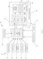
- FIGS. 1 A and 1 B are a schematic view of exemplary blood evaluation systems constructed in accordance with one aspect of the present invention
- FIG. 2 is a perspective, partially exploded view of the exemplary thermal exchange device of FIGS. 1 A and 1 B .
- FIG. 3 is a flowchart depicting an exemplary method for evaluating blood circulation in accordance with the methods of the present invention.
- FIG. 4 is an empirically derived three-dimensional surface corresponding to preferred values of patient circulation ratings based on measured patient information.
- FIG. 5 is a two-dimensional graph depicting an alternative representation of an empirically derived database of baseline circulation ratings as a function of patient information.
- FIG. 6 is a graph illustrating energy transfer between the treatment hand and the non-treatment hand of a patient.
- the present invention provides systems and methods for applying thermal energy to a human at normothermia to increase microcirculation, while evaluating blood circulation to monitor patient receptiveness to the treatment and to predict cardiovascular issues.
- the methods and apparatus of the present invention are expected to also provide beneficial results in treating a number of common ailments, including improved healing of acute and chronic wounds, and relief from neurological and hormone-relating ailments as described in U.S. Pat. Nos. 8,679,170, 9,066,781, 9,192,509, and 9,687,385 to Muehlbauer, assigned to the assignee of the present invention, the entire contents of each of which are incorporated herein by reference.
- a blood circulation evaluation system includes a measurement device collection and a thermal exchange device.
- the measurement device collection preferably has one or more measurement devices.
- the one or more measurement devices identifies the patient, measures patient information, e.g., height, weight, temperature, pulse, and/or blood pressure, and generates and transmits one or more signals indicative of the patient information to the thermal exchange device.
- the thermal exchange device may be constructed as described in any of the aforementioned Muehlbauer patents and applications.
- the thermal exchange device provides a negative pressure environment that assists in maintaining vasodilation and enhances the transfer to energy to an arteriovenous anastomosis (AVA) vascular area of the palm of a human hand.
- AVA vascular area may experience vasodilation from pre-treatment hyper-normothermia and/or heat delivered to the area from the thermal exchange member during treatment. This vasodilation increases the heat exchange between the thermal exchange member and the circulatory system by increasing blood flow and/or volume within the palm AVA's.
- An appendage chamber e.g., box enclosure, clamshell, glove-like, boot-like, or sleeve-like chamber, may be used to provide a negative pressure environment while providing heating or cooling to an appendage using a thermal exchange system. While embodiments of the invention will be described further below with respect to a chamber sized and shaped to receive a hand, it is recognized that the appendage chamber may be adapted for use with other appendages containing an AVA suitable for the vasodilation methods described herein, such as vasculatures in the foot.
- the thermal exchange device may also monitor the thermal energy transfer to the AVA vascular area and/or one or more separate measurement devices, and evaluate and store patient treatment information for early detection of cardiovascular issues.
- Blood evaluation system 100 includes thermal exchange device 200 and measurement device collection 101 .
- Blood evaluation system 100 also may include patient identifier 108 , biometric patch 120 , and oximeter 122 .
- Thermal exchange device 200 includes thermal exchange member 204 , control panel 206 , display 214 , alert mechanism 278 , and programmable controller 270 having processor 272 , receiver 274 , and memory 276 .
- Measurement device collection 101 may include a wheelchair base sized and shaped to permit a wheelchair to be positioned thereon.
- Measurement device collection 101 may include, separately or together in a common housing, height recorder 102 , temperature sensor 104 , weight scale 106 , pulse sensor 116 , and/or blood pressure sensor 118 , each in electrical communication with thermal exchange device 200 via data collection hub 110 .
- one or more of the devices of measurement device collection 101 may be coupled together and share a common housing, separate from the other devices of measurement device collection 101 .
- Data collection hub 110 may be electrically coupled to the devices of measurement device collection 101 , patient identifier 108 , biometric patch 120 , and oximeter 122 directly or wirelessly.
- data collection hub 110 may include a network of servers accessible over the Internet, e.g., cloud computing.
- height recorder 102 may have its own respective signal generator and transmitter for generating one or more signals indicative of the measured/input data, and transmitting the signal(s) wirelessly to data collection hub 110 .
- Data collection hub 110 may include signal generator 112 and transmitter 114 , and may be electrically coupled to, and designed to receive data from the devices of measurement device collection 100 , biometric patch 120 , and/or oximeter 122 .
- Data collection hub 110 may be programmed to estimate the patient's blood volume based on the collected patient data and to generate a signal indicative of the estimated blood volume.
- Patient data may include the patient's fitness level, e.g., whether the patient is muscular, thin, normal, or obese.
- Data collection hub 110 is designed to communicate the signal(s) to thermal exchange device 200 .
- Patient identifier 108 is designed to determine the identity of the patient and to electronically transmit information indicative of the patient's identity to data collection hub 110 .
- patient identifier 108 may include a retinal scanner designed to receive a patient retina blood vessel pattern to determine patient identity. The retinal scanner may be incorporated within eye goggles as part of measurement device collection 101 .
- patient identifier 108 may include a data entry interface configured to receive user input to determine patient identity, e.g., the patient may enter identifying information such as a name, fitness level or identification number directly into the data entry interface of patient identifier 108 .
- Patient identifier 108 alternatively may include a scanner that reads a bar code or QR code assigned to a patient that is maintained on the patient's paper file or an RFID transmitter on a patient-attached hospital bracelet. Upon determination of the patient's identity, patient identifier 108 may electronically transmit information indicative of the patient's identity to data collection hub 110 , where it is temporarily stored pending further transmission, as described below.
- Height recorder 102 is designed to digitally record a height of a patient and to electronically transmit information indicative of the patient's recorded height to data collection hub 110 .
- Height recorder 102 may be constructed using digital distance measurement technology or using measurement technology known in the art, e.g., a smartphone.
- Temperature sensor 104 is designed to measure temperature of a patient and to electronically transmit information indicative of the patient's measured temperature to data collection hub 110 .
- temperature sensor 104 may include an infrared ocular sensor for measuring ocular surface temperature of the patient. The infrared ocular sensor may be incorporated within eye goggles as part of measurement device collection 101 .
- temperature sensor 104 may include an infrared tympanic temperature sensor.
- Temperature sensor 104 may be constructed in accordance with digital temperature reading technology known in the art.
- Weight scale 106 is designed to measure a weight of a patient and to electronically transmit information indicative of the patient's measured weight to data collection hub 110 .
- Weight scale 106 may be constructed using digital measurement technology known in the art, e.g., as used in conventional analog and digital weight scales.
- pulse sensor 116 is designed to measure the pulse of the patient and to electronically transmit information indicative of the patient's recorded pulse to data collection hub 110
- blood pressure sensor 118 is designed to measure blood pressure of the patient and to electronically transmit information indicative of the patient's recorded blood pressure to data collection hub 110 .
- Biometric patch 120 is designed to measure skin temperature of the patient.
- biometric patch 120 may include one or more biometric patches (e.g., biometric patch by Qualcomm Life, Inc., San Diego, Calif.) that may be used to noninvasively measure patient skin temperature at a specific location, e.g., the palm of the non-treatment hand, and to electronically transmit information indicative of the patient's measured temperature to data collection hub 110 .
- Oximeter 122 is designed to noninvasively monitor a person's oxygen saturation at a specific location, e.g., on the non-treatment hand, and to electronically transmit information to data collection hub 110 for analysis.
- Signal generator 112 is configured to generate one or more signals indicative of the data received from height recorder 102 , temperature sensor 104 , weight scale 106 , patient identifier 108 , pulse sensor 116 , blood pressure sensor 118 , biometric patch 120 , and/or oximeter 122 .
- Transmitter 114 is configured to transmit, e.g., wirelessly, one or more signals to receiver 274 of processor 270 of thermal exchange device 200 .
- each device of measurement device collection 101 may individually include its own signal generator and transmitter such that each device generates a signal indicative of the recorded measurement and transmits the signal to programmable controller 270 of thermal exchange device 200 .
- the signals may be communicated to thermal exchange device 200 via a network of servers over the Internet, e.g., cloud computing.
- Programmable controller 270 may be electrically coupled to, and programmed to control, the components of thermal exchange device 200 described above, e.g., thermal exchange member 204 , control panel 206 , display 214 , and/or alert mechanism 278 .
- the programmable controller of thermal exchange device 200 may include processor 272 , e.g., one or more microprocessors, controllers, digital signal processors (DSPs), application specific integrated circuits (ASICs), field-programmable gate arrays (FPGAs), or equivalent discrete or integrated digital or analog logic circuitry, and the functions attributed to programmable controller 270 herein may be embodied as software, firmware, hardware, or any combination thereof.
- Programmable controller 270 may include memory 276 , e.g., non-transitory computer readable media, for storing data related to use of thermal exchange device 200 , such as user input, treatment times, treatment settings, detected errors, and the like.
- Memory 276 may store program instructions that, when executed by processor 272 of programmable controller 270 , cause programmable controller 270 and thermal exchange device 200 to provide the functionality ascribed to them herein, e.g., apply and monitor thermal energy transfer to an appendage of the patient within appendage chamber 202 using thermal energy member 204 .
- Memory 276 of programmable controller 270 may also store a database of patient identities, such that upon determination of patient identity using patient identifier 108 and receiving a signal indicative of the patient identity via receiver 274 , programmable controller 270 may evaluate and store patient treatment information based on patient identity.
- Each patient identity stored within memory 276 may contain information indicative of the patient's gender and/or age, and/or fitness level, previously inputted, e.g., via data entry interface of patient identifier 108 .
- Memory 276 of programmable controller 270 also may store software downloaded thereon or implemented as a program product for controlling thermal exchange device 200 and/or data analysis.
- the contents of memory 276 may further be stored on a tangible storage device such as machine-readable medium, e.g., tape, compact disk (CD), digital versatile disk (DVD), blu-ray disk (BD), external nonvolatile memory device, USB, cloud storage, or other tangible storage medium.
- Programmable controller 270 also may store in memory 276 therapy programs directed to treatment of specific maladies.
- therapy programs directed to treatment of specific maladies may include programs for increasing whole body circulation to address neurological ailments, such as migraine headaches, or circulatory issues, such as chronic wounds or reduced peripheral blood flow resulting from diabetes or immobility.
- Monitoring programs may also reside in programmable controller 270 wherein the duration and/or parameters of treatment, e.g., amount of heat transfer from thermal exchange member 204 , is determined by the change in temperature measured over time and/or at various locations throughout the body as indicated by thermal exchange device 200 and/or biometric patch 120 .
- thermal exchange device 200 may measure the time it takes to raise the temperature in the palm of the non-treatment hand of the patient by a delta of 12° F. as measured by biometric patch 120 , and then compare that time with that required by a healthy individual with similar physical characteristics as stored in a database of baseline healthy circulation ratings.
- thermal exchange device 200 may measure the time it takes to raise the temperature in the sole of the foot of the patient a delta of 10° F. as measured by biometric patch 120 , and then compare that time with that required by a healthy individual with similar physical characteristics as stored in a database of baseline healthy circulation ratings.
- thermal exchange device 200 may be used by a number of nursing home residents to provide relief from such ailments, and include preprogrammed therapeutic regimes (e.g., appropriate temperature adjustments for preselected durations) suitable for treating such residents.
- Preselected programs stored in thermal exchange device 200 may be loaded at the manufacturer, or generated using a suitable software program on a conventional personal computer and then uploaded to memory associated with programmable controller 270 via a data port, e.g., USB port or wirelessly via Bluetooth or WiFi.
- the data port further may be used to retrieve and/or store data on a tangible storage device related to use of thermal exchange device 200 , such as user input, treatment times, treatment settings, detected errors, and the like.
- Programmable controller 270 also may store in memory 276 patient treatment evaluation programs directed to evaluation of patient receptiveness to the treatment based on the monitored thermal energy transfer of the patient undergoing treatment or during surgery.
- memory 276 may store a database of baseline healthy circulation ratings and/or patient temperature data. Each baseline circulation rating is calculated based on the blood volume and thermal energy transfer over a specific time period and/or at various locations throughout the body of a healthy person using thermal exchange device 200 for a treatment period.
- Table 1 illustrates the baseline circulation ratings of healthy persons of age 56 and of age 57, each having a blood volume of 6100 mL, 6200 mL, 6300 mL, or 6400 mL, respectively.
- programmable controller 270 may be configured to monitor and store data indicative of thermal energy transfer of a patient using thermal exchange device 200 for a treatment period, calculate a circulation rating for the patient based on the patient's estimated blood volume and thermal energy transfer over a specific period and/or at various locations throughout the body, and compare the patient's circulation rating with the baseline circulation rating that corresponds with the patient based on the patient's estimated blood volume. For example, a patient having an estimated blood volume calculated from the patient data measured by height recorder 102 and weight scale 106 , and/or from age and/or gender based on the patient identity determined by patient identifier 108 , will have their patient circulation rating compared against the baseline circulation rating of a healthy person having the same or similar blood volume.
- Programmable controller 270 may be programmed to display the patient circulation rating via display 214 , and/or send an alert, e.g., visual or audio alert, to a user, e.g., the patient or a clinician, via alert mechanism 278 if the patient circulation rating is below a predetermined threshold.
- the patient circulation rating may be alphanumeric, e.g., a letter score on a scale of A-F or a numerical score on a scale of 0-1 or 1-100.
- Programmable controller 270 may also be programmed to analyze the patient's circulation ratings over time to detect negative trends, and to send and alert via alert mechanism 278 if a negative trend is detected. As such, system 100 may predict cardiovascular issues based on early detection of negative trends.
- Programmable controller 270 further may be programmed to send an alert, e.g., visual or audio alert, to a user, e.g., the patient or a clinician, via alert mechanism 278 if the patient's oxygen saturation measured by oximeter 122 falls outside a predetermined threshold, e.g., below 90% oxygen saturation, and/or if the patient's temperature at a specific location, e.g., temporal artery, measured by biometric patch 120 falls outside a predetermined threshold, e.g., below 96.8° F.
- a predetermined threshold e.g., below 90% oxygen saturation
- programmable controller 270 may be programmed to calculate and store patient-specific circulation ratings in memory 276 based on the patient identity determined using patient identifier 108 .
- Programmable controller 270 preferably also includes preprogrammed safety features, e.g., that shutdown the device if the apparatus sensors, such as temperature and negative pressure sensors disposed within thermal exchange device 200 , fail or become disconnected. Programmable controller 270 also may include an error circuit that displays error codes on display 214 .
- Programmable controller 270 may be programmed to direct thermal exchange member 204 to heat or cool to a temperature responsive to biometric patch data, user input at control panel 206 or to a preselected therapy regime.
- programmable controller 270 is programmed to heat thermal exchange member to a high, medium, or low temperature, e.g., 109.4° F., 108.4° F., or 107.4° F., respectively, based on user input received at control panel 206 .
- Programmable controller 270 further may include a clock application that directs thermal exchange member to heat or cool at the temperature for a time. e.g., 5, 10, 15, 20, 25, or 30 minutes, responsive to user input at control panel 206 or to a preselected therapy regime.
- system 100 ′ of FIG. 1 B includes measurement device collection 101 ′ and thermal exchange device 200 ′.
- Measurement device collection 101 ′ includes, separately or together in a common housing, height recorder 102 ′, temperature sensor 104 ′, weight scale 106 ′, pulse sensor 116 ′, and/or blood pressure sensor 118 ′
- thermal exchange device 200 ′ includes programmable controller 270 ′, thermal exchange member 204 ′, control panel 206 , alert mechanism 278 ′, and display 214 ′.
- System 100 ′ further may include patient identifier 108 ′, biometric patch 120 ′, and oximeter 122 ′.
- System 100 ′ of FIG. 1 B is distinct from system 100 of FIG. 1 A in that the data collection hub is integrated with programmable controller 270 ′ such that height recorder 102 ′, temperature sensor 104 ′, weight scale 106 ′, pulse sensor 116 ′, blood pressure sensor 118 ′, patient identifier 108 ′, biometric patch 120 ′, and oximeter 122 ′, each directly transmit signal(s) indicative of the measured/input data to receiver 274 ′ of programmable controller 270 ′.
- Thermal exchange device 200 may communicate with devices of measurement device collection 101 directly or via data collection hub 110 .
- thermal exchange device 200 includes thermal exchange member 204 , control panel 206 , display 214 , alert mechanism 278 , and programmable controller 270 having processor 272 , receiver 274 , and memory 276 .
- Thermal exchange device 200 further may include appendage chamber 202 , thermal exchange member 204 , and control panel 206 , and may be constructed as described in commonly assigned U.S. patent application Serial No. 2016/0022476, the entirety of which is hereby incorporated by reference.
- Appendage chamber 202 includes a housing sized and shaped to accept a human appendage containing an AVA such as a hand, for example, through appendage opening 208 , which may also facilitate a blood pressure and pulse sensor.
- appendage chamber 202 includes a durable and relatively rigid plastic or metal alloy, or combination thereof, of which individual components may be formed using conventional injection-molding or stamping processes.
- Appendage chamber 202 preferably includes pressure chamber insert (PCI) 210 that may be partially or fully transparent such that a user and/or physician may monitor the hand during treatment.
- PCI 210 includes a rigid, substantially transparent plastic or polymer, such as polycarbonate, which allows the user or care-giver to visualize placement of the hand within the chamber.
- Thermal exchange member 204 may be disposed within appendage chamber 202 and may include a plastic, biocompatible metal, such as aluminum, metal alloy, or the like. Thermal exchange member 204 is configured to selectively heat or cool blood flowing through the AVA of the appendage disposed within appendage chamber 202 .
- thermal exchange member 204 may be configured to be heated to approximately 107.4° F., 108.4° F., 109.4° F., between 107-110° F., between 105-112° F., or between 100-120° F., and may be configured to be cooled to approximately 60.8° F., between 60-62° F., between 58-64° F., or between 58-95° F.
- thermal exchange member 204 includes a Peltier device configured to heat and/or cool thermal exchange member 204 .
- Thermal exchange member 204 also may include suitable components for resistive heating such as a conductive wire configured to receive an electrical current and release heat.
- Thermal exchange member 204 may be shaped and sized to contact an appendage, for example, a palm of the hand.
- thermal exchange member 204 includes palm pad 212 (shown in FIG. 2 ) that extends outwardly from thermal exchange member 204 to promote enhanced contact with the palm.
- Control panel 206 is configured to provide a user interface for a user and/or clinician or care-giver to control operations of thermal exchange device 200 .
- Control panel 206 may include buttons, assorted lighting sources, e.g., LEDs, and/or a display, e.g., an LCD or LED readout, that may be a touch screen.
- Appendage chamber 202 may include a plurality of feet, e.g., feet coupled to a front portion of the base of appendage chamber 202 and feet coupled to a rear portion of the base of appendage chamber 202 .
- the plurality of feet may be configured to be adjusted to raise or lower a portion of appendage chamber 202 .
- the rear feet may be adjusted to increase the distance between the rear feet and the base of appendage chamber 202 , thereby raising the rear portion of thermal exchange device 200 .
- the rear feet are coupled to the base of appendage chamber 202 via a threaded male member that is screwed into a threaded female member in appendage chamber 202 to adjust the distance between the rear feet and the base of appendage chamber 202 .
- a user may adjust the rear feet such that appendage opening 208 is angled in a manner that the user may insert their hand into appendage opening 208 and comfortably rest their elbow on a surface, e.g., table, desk, or medical cart, holding thermal exchange device 200 .
- PCI 210 may include appendage opening 208 , cuff 240 , expandable cuff 242 , cuff seal 244 , PCI edges 246 , PCI base 248 , PCI base opening 250 , and positive pressure input 252 .
- Cuff 240 may include a plastic, biocompatible metal, such as aluminum, metal alloy, or the like and is shaped and sized to accept an appendage through appendage opening 208 .
- cuff 240 is elliptically shaped although, as would be understood by one of ordinary skill in the art, cuff 240 may take other shapes including a rectangle or a rectangle with rounded corners.
- Cuff 240 is coupled to expandable cuff 242 .
- Expandable cuff 242 is configured to expand to seal around an appendage placed within PCI 210 through appendage opening 208 .
- Expandable cuff 242 may include a rubber, such as latex, nitrile, or neoprene, and/or plastic, such as polyvinyl chloride, polyethylene, or polyurethane and may be between 1-20 mil thick, preferably about 2 mil.
- Cuff 240 may be coupled to the main body of PCI 210 via cuff seal 244 .
- Cuff seal 244 is configured to couple cuff 240 to the main body of PCI 210 , and may include a suitable sealing material such as tape.
- Cuff 240 optionally may be removable from PCI 210 .
- PCI 210 is configured to be removable from appendage chamber 202 .
- PCI 210 may be coupled to appendage chamber 202 by placing PCI edges 246 on chamber ledges 254 of appendage chamber 202 such that PCI base 248 contacts appendage chamber 202 , optionally at sealing gasket 258 , and thermal exchange member 204 is disposed within PCI base opening 250 .
- PCI positive pressure input 252 is configured to be disposed within chamber aperture 256 of appendage chamber 202 .
- control panel 206 includes display 214 , on/off button 216 , on/off LED 218 , ready symbol 220 , ready LED 222 , left button 224 , right button 226 , up button 228 , down button 230 , and accept button 232 .
- Thermal exchange device 200 further may include sealing gasket 258 that is configured to couple to PCI base 248 to maintain negative pressure within PCI 210 when PCI 210 is attached to appendage chamber 202 .
- Sealing gasket 258 is disposed within appendage chamber 202 .
- FIG. 2 depicts sealing gasket 258 coupled to the base of appendage chamber 202
- sealing gasket 258 may alternatively be coupled directly to PCI base 248 when PCI 210 is removed from appendage chamber 202 .
- sealing gasket 258 includes a deformable material that supports PCI base 248 when it contacts sealing gasket 258 to create an air-tight seal.
- sealing gasket 258 includes a groove that accepts PCI base 248 therein.
- Pressure source 262 and circuitry housing 264 having a programmable controller coupled thereto may be disposed within appendage chamber 202 .
- Pressure source 262 is a suitable device for pumping fluid, e.g., air, and for creating and maintaining negative pressure in appendage chamber 202 at a suitable pumping rate, e.g., greater than about 4 liters per minute.
- pressure source 262 is a diaphragm pump.
- Pressure source 262 may be configured to apply positive pressure to expand expandable cuff 242 to seal around an appendage placed therein by pumping a fluid into expandable cuff 242 .
- Pressure source also may be configured to apply negative pressure within appendage chamber 202 , including PCI 210 , and to create an air-tight seal between PCI base 248 and sealing gasket 258 when an appendage is placed therein.
- pressure source 262 includes a single motor-driven pump configured simultaneously to apply negative pressure to the appendage and to selectably apply positive pressure to expand expandable cuff 242 when the appendage is placed within appendage chamber 202 .
- the pump may simultaneously apply negative pressure within the appendage chamber and positive pressure within the cuff, may selectably apply negative pressure only, and/or may selectably apply positive pressure only.
- Cuff 242 may also contain sensors to monitor blood pressure and pulse.
- Pressure source 262 may include positive pressure connector 263 and negative pressure connector 265 .
- Positive pressure connector 263 includes a suitable coupling mechanism, illustratively a male protrusion, for coupling to a positive pressure line.
- Pressure source 262 may be coupled to expandable cuff 242 via the positive pressure line coupled between positive pressure connector 263 of pressure source 262 and PCI positive pressure input 252 .
- Negative pressure connector 265 includes a suitable coupling mechanism, illustratively a male protrusion, for coupling to a negative pressure line.
- Pressure source 262 may be coupled to appendage chamber 202 , including to PCI 210 , via the negative pressure line coupled between negative pressure connector 265 of pressure source 262 and a negative pressure opening beneath thermal exchange member 204 such that pressure source 262 may apply negative pressure within appendage chamber 202 , including within PCI 210 , through the negative pressure opening.
- pressure source 262 is a single motor-driven negative pressure pump
- exhaust from the pump may be used to selectably expand expandable cuff 242 via the positive pressure line while the pump applies negative pressure within appendage chamber 202 , including within PCI 210 , via the negative pressure line.
- pressure source 262 is configured to maintain the negative pressure within the appendage chamber between ⁇ 20 mmHg and ⁇ 40 mmHg or between ⁇ 1 mmHg and ⁇ 50 mmHg.
- Pressure source 262 assists in maintaining vasodilation and to enhance the transfer to energy to an arteriovenous anastomosis vascular area of the appendage, e.g., located in the palm of a hand.
- the arteriovenous anastomosis vascular area may experience vasodilation from pre-treatment hyper-normothermia and/or heat delivered to the area from thermal exchange member 204 during treatment.
- Appendage chamber 202 may include power interface 266 that connects to an AC or DC power source to power thermal exchange device 200 and/or charge at least one battery within appendage chamber 202 .
- thermal exchange device 200 is powered with at least one replaceable battery and power interface 266 may be omitted.
- Appendage chamber 202 may further include a plurality of vent holes 268 configured to expel heat resulting from operation of thermal exchange device 200 therethrough.
- thermal exchange device 200 The electronics of thermal exchange device 200 are coupled to control panel 206 , so that programmable controller 270 actuates thermal exchange device 200 in accordance with input commands or selection of pre-programmed therapy regimes input via control panel 206 .
- programmable controller 270 detects that left button 224 or right button 226 is pressed, programmable controller 270 directs thermal exchange member 204 to decrease or increase temperature, respectively.
- programmable controller 270 detects that up button 228 or down button 230 is pressed, programmable controller 270 directs a clock application to increase or decrease, respectively, a countdown timer for treatment.
- the identity of the patient is determined using patient identifier 108 .
- the patient identifier may identify the patient by, for example, scanning the patients' retina blood vessel pattern via a retinal scanner, receiving user input via a data entry interface, or by scanning a bar code or QR code.
- Patient identity may also include the patient's age and/or gender, which may be previously entered and stored in memory 276 for each patient.
- patient information including height, temperature, weight, pulse, fitness level, and/or blood pressure may be measured or input via height recorder 102 , temperature sensor 104 , weight scale 106 , patient identifier 108 , pulse sensor 116 , and/or blood pressure sensor 118 , respectively.
- Signal generator 112 of data collector hub 110 may generate a signal indicative of the measured patient information and transmit the signal to thermal exchange device 200 via transmitter 114 .
- the patient's blood volume is estimated based on the collected patient information.
- signal generator 112 may be programmed to estimate the patient's blood volume directly from the patient information received from height recorder 102 and weight scale 106 , and optionally the patient's age and/or gender and/or fitness based on the patient's identity received from patient identifier 108 , and generate a signal indicative of the estimated blood volume for transmission to thermal exchange device 200 via transmitter 114 to receiver 274 .
- programmable controller 270 may be programmed to cause processor 272 to estimate the patient's blood volume based on the signal indicative of the patient information received from data collection hub 110 , and optionally the patient's age and/or gender and/or fitness stored in memory 276 based on the patient's identity received from patient identifier 108 .
- thermal exchange device 200 directs thermal exchange device 200 to provide the functionality ascribed to them herein, e.g., apply and monitor thermal energy transfer to an appendage of the patient within appendage chamber 202 using thermal energy member 204 .
- thermal exchange device 200 may monitor the amount of heat transfer from thermal exchange member 204 , by measuring the change in temperature measured over time and/or at various locations throughout the body as indicated by biometric patch 120 .
- thermal exchange device 200 may measure the time it takes to raise the temperature of a specific location of the patient by a predetermined amount as measured by biometric patch 120 .
- the monitored thermal energy transfer may be stored in memory 276 .
- processor 272 of programmable controller 270 calculates a patient circulation rating based on the patient information measured during step 304 and the thermal energy transfer monitored and stored during steps 308 and/or 309 .
- the patient circulation rating may be calculated by dividing the thermal energy transfer (Joules/Infused), e.g., measured for two minutes after plateau for two minutes, by the estimated blood volume (milliliters).
- processor 272 of programmable controller 270 compares the patient circulation rating calculated during step 310 against a baseline circulation rating of a healthy person having the same or similar blood volume as the patient, the baseline circulation rating selected from an empirically derived database or graph of baseline circulation ratings stored within memory 276 , as described below with respect to FIG. 4 .
- the patient's current circulation rating may be compared to prior recorded levels for that patient to identify improvement (or lack thereof) between successive measurements.
- the patient circulation rating may be alphanumeric, and may be displayed via display 214 of thermal exchange device 200 .
- processor 272 of programmable controller 270 determines whether the patient circulation rating is within a predetermined threshold. For example, if the patient circulation rating is on a scale of 0-1, the predetermined threshold may be 0.65, or if the patient circulation rating is on a scale of 1-100, the predetermined threshold may be 65, or if the patient circulation rating is on a scale of A-F, the predetermined threshold may be a D. In one embodiment, the predetermined threshold may be calculated for each specific patient based on patient identity, measured patient information, and previous treatment data.
- processor 272 of programmable controller 270 may direct alert mechanism 278 to generate an alert, e.g., a visual and/or audible alert and/or external transmission e.g. wireless transmission. If processor 272 of programmable controller 270 determines that the patient circulation rating is within the predetermined threshold, at step 318 , programmable controller 270 may store the patient circulation rating within memory 276 based on the patient's identity.
- processor 272 of programmable controller 270 may compare a current patient circulation rating to previous circulation ratings for a given patient stored within memory 276 during step 318 , and determine whether there is a negative trend. If processor 272 of programmable controller 270 determines that there is a negative trend, method 300 proceeds to step 316 and generates an alert via alert mechanism 278 . In addition, programmable controller 270 may also cause display 214 to display diagnostics regarding the negative trend detected at step 320 . Accordingly, blood evaluation system 100 may predict cardiovascular issues based on the diagnostics. If processor 272 of programmable controller 270 does not determine that there is a negative trend, method 300 returns to step 308 and programmable controller 270 continues to direct thermal exchange device 200 to provide the functionality ascribed to them herein.
- FIG. 4 illustrates an empirically derived three-dimensional surface corresponding to preferred values of patient circulation ratings based on measured and/or inputted patient information, e.g., height, weight, age, gender, and fitness, for which a patient's blood volume may be estimated by either data collection hub 110 or processor 272 as described above.
- patient information e.g., height, weight, age, gender, and fitness
- a baseline value for a specific patient's blood circulation rating may be determined.
- FIG. 5 is a two-dimensional graph depicting an alternative representation of an empirically derived database of baseline circulation ratings as a function of patient information, e.g., body mass index (BMI), for which a patient's blood volume may be estimated by either data collection hub 110 or processor 272 as described above.
- BMI body mass index
- a patient's BMI may be calculated by either data collection hub 110 or processor 272 as a function of the patient's height and weight.
- a patient may be predicted to have an optimum blood circulation rating within a specified threshold, e.g., plus or minus 10% of the value of the curve specified in FIG. 5 for a specific BMI.
Landscapes
- Health & Medical Sciences (AREA)
- Life Sciences & Earth Sciences (AREA)
- Engineering & Computer Science (AREA)
- General Health & Medical Sciences (AREA)
- Veterinary Medicine (AREA)
- Biophysics (AREA)
- Biomedical Technology (AREA)
- Heart & Thoracic Surgery (AREA)
- Medical Informatics (AREA)
- Molecular Biology (AREA)
- Surgery (AREA)
- Animal Behavior & Ethology (AREA)
- Physics & Mathematics (AREA)
- Public Health (AREA)
- Pathology (AREA)
- Physiology (AREA)
- Cardiology (AREA)
- Hematology (AREA)
- Artificial Intelligence (AREA)
- Computer Vision & Pattern Recognition (AREA)
- Psychiatry (AREA)
- Signal Processing (AREA)
- Vascular Medicine (AREA)
- Pulmonology (AREA)
- Measuring And Recording Apparatus For Diagnosis (AREA)
Abstract
Description
| TABLE 1 | ||||
| Milliliters | At Plateau | Biometric Patch | AHI1- | |
| Blood Volume | Joules/Infused | Temperature | Normal | |
| Age | (V) | (J)2 | Increase3 | W/V |
| 56 | 6100 | 660 | Profile 1A | 0.1082 |
| 6200 | 672 | Profile 1B | 0.1084 | |
| 6300 | 684 | Profile 1C | 0.1086 | |
| 6400 | 694 | Profile 1D | 0.1088 | |
| 57 | 6100 | 657 | Profile 2A | 0.1077 |
| 6200 | 669 | Profile 2B | 0.1079 | |
| 6300 | 681 | Profile 2C | 0.1081 | |
| 6400 | 693 | Profile 2D | 0.1083 | |
| 1AHI = AVACEN Health Index | ||||
| 2Total energy infused over a specific time period, e.g., 2 minutes at 10-minute point | ||||
| 3Energy transfer between the treatment hand and the non-treatment hand (FIG. 6). | ||||
Claims (11)
Priority Applications (1)
| Application Number | Priority Date | Filing Date | Title |
|---|---|---|---|
| US15/887,951 US11684282B2 (en) | 2017-02-03 | 2018-02-02 | Systems and methods for evaluating blood circulation and early detection of cardiovascular issues |
Applications Claiming Priority (2)
| Application Number | Priority Date | Filing Date | Title |
|---|---|---|---|
| US201762454336P | 2017-02-03 | 2017-02-03 | |
| US15/887,951 US11684282B2 (en) | 2017-02-03 | 2018-02-02 | Systems and methods for evaluating blood circulation and early detection of cardiovascular issues |
Publications (2)
| Publication Number | Publication Date |
|---|---|
| US20180220898A1 US20180220898A1 (en) | 2018-08-09 |
| US11684282B2 true US11684282B2 (en) | 2023-06-27 |
Family
ID=61521810
Family Applications (1)
| Application Number | Title | Priority Date | Filing Date |
|---|---|---|---|
| US15/887,951 Active 2039-11-26 US11684282B2 (en) | 2017-02-03 | 2018-02-02 | Systems and methods for evaluating blood circulation and early detection of cardiovascular issues |
Country Status (2)
| Country | Link |
|---|---|
| US (1) | US11684282B2 (en) |
| WO (1) | WO2018144948A1 (en) |
Families Citing this family (3)
| Publication number | Priority date | Publication date | Assignee | Title |
|---|---|---|---|---|
| CN111904408B (en) * | 2019-05-07 | 2024-08-02 | 上海智全钧丰医疗科技有限公司 | Noninvasive microcirculation quantitative diagnosis system and quantitative processing method thereof |
| US11688508B2 (en) * | 2019-09-03 | 2023-06-27 | Edgewater Safety Systems, Inc. | Biometric status sensing media therapy system and methods of use |
| JP2021083482A (en) * | 2019-11-25 | 2021-06-03 | 株式会社村田製作所 | Device for measuring inside of oral cavity and system for measuring inside of oral cavity |
Citations (72)
| Publication number | Priority date | Publication date | Assignee | Title |
|---|---|---|---|---|
| US1399095A (en) | 1919-12-02 | 1921-12-06 | Sr Jean F Webb | Vacuo-thermic-body-treatment appliance |
| US1740624A (en) | 1927-06-25 | 1929-12-24 | Peter J Peel | Apparatus for the application of electric hydro-physio therapeutics |
| US2235138A (en) | 1938-04-28 | 1941-03-18 | Halton A Billetter | Therapeutical apparatus |
| US3859989A (en) | 1973-01-05 | 1975-01-14 | Theodore E Spielberg | Therapeutic cuff |
| US4329997A (en) | 1980-05-23 | 1982-05-18 | Yampert H Donn De | Cold/hot compression and elevation apparatus |
| US4735195A (en) | 1986-04-01 | 1988-04-05 | Blum Alvin S | Device encouraging periodic joint motion and muscle activity |
| US5027795A (en) | 1989-08-04 | 1991-07-02 | Kabushiki Kaisha Kato Haguruma Kogyosho | Massage machine for automobile |
| US5369807A (en) | 1993-03-17 | 1994-12-06 | Cho; Kurt N. | Therapeutic glove |
| US5425742A (en) | 1994-03-28 | 1995-06-20 | Patrick S. Quigley | Use of hollow hypobaric chambers on body parts for increasing blood flow, reducing pressure and decreasing pain |
| US5637076A (en) | 1992-05-26 | 1997-06-10 | Ergomedics, Inc. | Apparatus and method for continuous passive motion of the lumbar region |
| US5683438A (en) | 1995-03-10 | 1997-11-04 | Stanford University | Apparatus and method for core body warming of mammals experiencing hypothermia |
| US5688208A (en) | 1995-11-03 | 1997-11-18 | Plemmons; David | Limb exercise/therapy apparatus |
| US5693004A (en) | 1996-03-11 | 1997-12-02 | Lord Corporation | Controllable fluid rehabilitation device including a reservoir of fluid |
| US5733318A (en) | 1994-09-30 | 1998-03-31 | Augustine Medical, Inc. | Convertible thermal blanket |
| WO1998040039A1 (en) | 1997-03-10 | 1998-09-17 | Aquarius Medical Corporation | Improved apparatus and method for the core body warming of mammals experiencing hypothermia |
| EP0926980A2 (en) | 1996-07-30 | 1999-07-07 | Itamar Medical (C.M.) 1997 Ltd. | Method and apparatus for the non-invasive detection of medical conditions by monitoring peripheral arterial tone |
| US6149674A (en) | 1997-11-07 | 2000-11-21 | Hill-Rom, Inc. | Patient thermal regulation system |
| US6287252B1 (en) * | 1999-06-30 | 2001-09-11 | Monitrak | Patient monitor |
| US6315696B1 (en) | 1997-01-30 | 2001-11-13 | Robin Goldstein | Liquid immersion therapeutic device |
| US20010049546A1 (en) | 2000-02-08 | 2001-12-06 | Israel Dvoretzky | Multi-purpose drug and heat therapy treatment system |
| US6434423B1 (en) | 2000-05-08 | 2002-08-13 | Jesse Ross | High frequency electro magnetic field treatment of abnormalities |
| US20020151826A1 (en) | 1999-05-11 | 2002-10-17 | John S. Ramey | Massage apparatus and methods |
| US20030004083A1 (en) | 1998-07-29 | 2003-01-02 | The Procter & Gamble Company | Particulate compositions having a plasma-induced, graft polymerized, water-soluble coating and process for making same |
| WO2003007804A2 (en) | 2001-07-18 | 2003-01-30 | Porrata Group Llc | Apparatus and method for treating carpal tunnel syndrome |
| US20030040783A1 (en) | 1999-09-21 | 2003-02-27 | Salmon Andrew Paul Maxwell | Warming apparatus |
| US20030097163A1 (en) | 2001-11-21 | 2003-05-22 | Kane John R. | Apparatus and method for manipulating core body temperature |
| US6602277B2 (en) | 2000-06-09 | 2003-08-05 | The Board Of Trustees Of The Leland Stanford Junior University | Methods and devices for manipulating the themoregulatory status of a mammal |
| US6656208B2 (en) | 2000-04-20 | 2003-12-02 | The Board Of Trustees Of The Leland Stanford Junior University | Methods and devices for extracting thermal energy from the body core of a mammal |
| US6673099B2 (en) | 2000-06-09 | 2004-01-06 | The Board Of Trustees Of The Leland Stanford Junior University | Methods and devices for prevention of hypothermia in a mammal during prolonged exposure to extreme cold |
| US20040015127A1 (en) | 2001-06-22 | 2004-01-22 | Silver Brian H. | Breastshield with multi-pressure and expansible chamber construction, related breastpump and method |
| WO2004046551A1 (en) | 2002-11-20 | 2004-06-03 | Myotoku Ltd. | Positive and negative pressure supply device |
| US6752794B2 (en) | 2000-11-29 | 2004-06-22 | Hill-Rom Services, Inc. | Vacuum therapy and cleansing dressing for wounds |
| US20050051174A1 (en) | 2003-09-08 | 2005-03-10 | Emerson George P. | Insufflation-exsufflation system with percussive assist for removal of broncho-pulmonary secretions |
| WO2005030101A1 (en) | 2003-09-24 | 2005-04-07 | Dynatherm Medical, Inc. | Methods and apparatus for adjusting body core temperature |
| US20050103353A1 (en) | 2003-11-14 | 2005-05-19 | Grahn Dennis A. | Controlled heat transfer with mammalian bodies |
| US7169119B2 (en) | 2005-04-25 | 2007-01-30 | Chan Yung C | Arthritic hand or foot treatment apparatus |
| US20070123962A1 (en) | 2000-06-09 | 2007-05-31 | Grahn Dennis A | Methods and devices for manipulating the thermoregulatory status of a mammal |
| US20070240247A1 (en) | 2006-03-07 | 2007-10-18 | Beck Emily A | Antimicrobial protective hand device |
| US20080004549A1 (en) | 2006-06-12 | 2008-01-03 | Anderson Paul J | Negative pressure wound treatment device, and methods |
| US20080021531A1 (en) | 2003-09-24 | 2008-01-24 | Kane John R | Methods and apparatus for increasing blood circulation |
| US20080034466A1 (en) | 2004-12-29 | 2008-02-14 | Jean Zicarelli | Handwear item having a flexible impermeable liner |
| US20080077205A1 (en) | 2006-09-27 | 2008-03-27 | Gaymar Industries, Inc. | Cooling-normothermic-heating device with activated negative pressure system |
| US20080077201A1 (en) | 2006-09-26 | 2008-03-27 | Juniper Medical, Inc. | Cooling devices with flexible sensors |
| US20080132816A1 (en) | 2006-12-04 | 2008-06-05 | Kane John Roy | Methods and Apparatus for Adjusting Blood Circulation |
| US20080132976A1 (en) | 2006-12-04 | 2008-06-05 | Kane John Roy | Methods and apparatus for adjusting blood circulation |
| US20080208088A1 (en) | 2007-02-22 | 2008-08-28 | Gaymar Industries, Inc. | Negative pressure, compression therapy device |
| US20080249593A1 (en) | 2007-04-05 | 2008-10-09 | Cazzini Karl H | Negative/positive pressure, thermal energy therapy device |
| US20080300515A1 (en) | 2006-12-28 | 2008-12-04 | Mario Nozzarella | Focused Chest Compression System and Method of Using Same |
| US20090036959A1 (en) | 2002-12-31 | 2009-02-05 | Thermanor As | Device for applying a pulsating pressure to a local region of the body and the applications thereof |
| US20090043237A1 (en) * | 2003-10-08 | 2009-02-12 | Caridianbct, Inc. | Methods and devices for processing blood |
| US20090048649A1 (en) | 2007-08-16 | 2009-02-19 | Gaymar Industries, Inc. | Heat transfer device: seal and thermal energy contact units |
| US20090112298A1 (en) | 2007-10-31 | 2009-04-30 | Gaymar Industries, Inc. | High efficiency thermal energy transfer pad |
| US20090177184A1 (en) * | 2008-01-09 | 2009-07-09 | Christensen Scott A | Method and apparatus for improving venous access |
| US20090240191A1 (en) | 2007-11-07 | 2009-09-24 | Aoti, Inc. | Pressure compensating seal with positive feedback |
| US20100106230A1 (en) | 2008-10-29 | 2010-04-29 | Gaymar Industries, Inc. | Negative Pressure, Thermal Energy Transfer Device That Also Provides Positive Pressure to the Patient |
| US20100106199A1 (en) | 2008-06-16 | 2010-04-29 | Sawa Anna G U | Venting/pressure adjustment to aid in delivery of material into an anatomic region via a cannula |
| US20100152633A1 (en) | 2008-12-16 | 2010-06-17 | Thermanor As | Portable patient temperature adjustment apparatus and method |
| US20100152821A1 (en) | 2008-12-16 | 2010-06-17 | Thermanor As | Portable patient temperature adjustment apparatus and method |
| US20100262048A1 (en) | 2007-10-26 | 2010-10-14 | Youichi Shinomiya | Passive exercise machine |
| US20100280448A1 (en) | 2004-12-21 | 2010-11-04 | Nuk Usa Llc | Electric breast pump |
| US20110000484A1 (en) | 2009-07-02 | 2011-01-06 | Cook Incorporated | Vascular therapy using negative pressure |
| US20110071465A1 (en) | 2008-01-23 | 2011-03-24 | Deka Research & Development | Fluid volume determination for medical treatment system |
| US7972287B2 (en) | 2006-09-08 | 2011-07-05 | Gaymar Industries, Inc. | Heat transfer cuff |
| US20110172749A1 (en) | 2010-01-08 | 2011-07-14 | Christensen Scott A | Methods and apparatus for enhancing vascular access in an appendage to enhance therapeutic and interventional procedures |
| WO2012012683A1 (en) | 2010-07-23 | 2012-01-26 | Avacen, Inc. | Methods and apparatus for therapeutic application of thermal energy |
| US20120123322A1 (en) | 2010-07-07 | 2012-05-17 | Deka Products Limited Partnership | Medical treatment system and methods using a plurality of fluid lines |
| US20130165847A1 (en) | 2011-11-04 | 2013-06-27 | Deka Products Limited Partnership | Medical treatment system and methods using a plurality of fluid lines |
| US20130184638A1 (en) | 2008-01-23 | 2013-07-18 | Deka Products Limited Partnership | Medical treatment system and methods using a plurality of fluid lines |
| US8569566B2 (en) | 2003-10-28 | 2013-10-29 | Smith & Nephew, Plc | Wound cleansing apparatus in-situ |
| US20140257440A1 (en) * | 2013-03-11 | 2014-09-11 | Avacen, Inc | Methods and apparatus for therapeutic application of thermal energy including blood viscosity adjustment |
| WO2016025438A1 (en) | 2014-08-11 | 2016-02-18 | The Board Of Trustees Of The University Of Illinois | Epidermal devices for analysis of temperature and thermal transport characteristics |
| US9687385B2 (en) | 2013-03-11 | 2017-06-27 | Avacen, Inc. | Methods and apparatus for therapeutic application of thermal energy including blood viscosity adjustment |
-
2018
- 2018-02-02 US US15/887,951 patent/US11684282B2/en active Active
- 2018-02-02 WO PCT/US2018/016749 patent/WO2018144948A1/en not_active Ceased
Patent Citations (98)
| Publication number | Priority date | Publication date | Assignee | Title |
|---|---|---|---|---|
| US1399095A (en) | 1919-12-02 | 1921-12-06 | Sr Jean F Webb | Vacuo-thermic-body-treatment appliance |
| US1740624A (en) | 1927-06-25 | 1929-12-24 | Peter J Peel | Apparatus for the application of electric hydro-physio therapeutics |
| US2235138A (en) | 1938-04-28 | 1941-03-18 | Halton A Billetter | Therapeutical apparatus |
| US3859989A (en) | 1973-01-05 | 1975-01-14 | Theodore E Spielberg | Therapeutic cuff |
| US4329997A (en) | 1980-05-23 | 1982-05-18 | Yampert H Donn De | Cold/hot compression and elevation apparatus |
| US4735195A (en) | 1986-04-01 | 1988-04-05 | Blum Alvin S | Device encouraging periodic joint motion and muscle activity |
| US5027795A (en) | 1989-08-04 | 1991-07-02 | Kabushiki Kaisha Kato Haguruma Kogyosho | Massage machine for automobile |
| US5637076A (en) | 1992-05-26 | 1997-06-10 | Ergomedics, Inc. | Apparatus and method for continuous passive motion of the lumbar region |
| US5369807A (en) | 1993-03-17 | 1994-12-06 | Cho; Kurt N. | Therapeutic glove |
| US5425742A (en) | 1994-03-28 | 1995-06-20 | Patrick S. Quigley | Use of hollow hypobaric chambers on body parts for increasing blood flow, reducing pressure and decreasing pain |
| US5733318A (en) | 1994-09-30 | 1998-03-31 | Augustine Medical, Inc. | Convertible thermal blanket |
| US5683438A (en) | 1995-03-10 | 1997-11-04 | Stanford University | Apparatus and method for core body warming of mammals experiencing hypothermia |
| US5688208A (en) | 1995-11-03 | 1997-11-18 | Plemmons; David | Limb exercise/therapy apparatus |
| US5693004A (en) | 1996-03-11 | 1997-12-02 | Lord Corporation | Controllable fluid rehabilitation device including a reservoir of fluid |
| EP0926980A2 (en) | 1996-07-30 | 1999-07-07 | Itamar Medical (C.M.) 1997 Ltd. | Method and apparatus for the non-invasive detection of medical conditions by monitoring peripheral arterial tone |
| US6315696B1 (en) | 1997-01-30 | 2001-11-13 | Robin Goldstein | Liquid immersion therapeutic device |
| WO1998040039A1 (en) | 1997-03-10 | 1998-09-17 | Aquarius Medical Corporation | Improved apparatus and method for the core body warming of mammals experiencing hypothermia |
| US6149674A (en) | 1997-11-07 | 2000-11-21 | Hill-Rom, Inc. | Patient thermal regulation system |
| US20030004083A1 (en) | 1998-07-29 | 2003-01-02 | The Procter & Gamble Company | Particulate compositions having a plasma-induced, graft polymerized, water-soluble coating and process for making same |
| US20020151826A1 (en) | 1999-05-11 | 2002-10-17 | John S. Ramey | Massage apparatus and methods |
| US6287252B1 (en) * | 1999-06-30 | 2001-09-11 | Monitrak | Patient monitor |
| US20030040783A1 (en) | 1999-09-21 | 2003-02-27 | Salmon Andrew Paul Maxwell | Warming apparatus |
| US20010049546A1 (en) | 2000-02-08 | 2001-12-06 | Israel Dvoretzky | Multi-purpose drug and heat therapy treatment system |
| US6656208B2 (en) | 2000-04-20 | 2003-12-02 | The Board Of Trustees Of The Leland Stanford Junior University | Methods and devices for extracting thermal energy from the body core of a mammal |
| US20060111766A1 (en) | 2000-04-20 | 2006-05-25 | Grahn Dennis A | Methods and devices for extracting thermal energy from the body core of a mammal |
| US6974442B2 (en) | 2000-04-20 | 2005-12-13 | The Board Of Trustees Of The Leland Stanford Junior University | Methods and devices for extracting thermal energy from the body core of a mammal |
| US6434423B1 (en) | 2000-05-08 | 2002-08-13 | Jesse Ross | High frequency electro magnetic field treatment of abnormalities |
| US6966922B2 (en) | 2000-06-09 | 2005-11-22 | The Board Of Trustees Of The Leland Stanford Junior University | Methods and devices for prevention of hypothermia in a mammal during prolonged exposure to extreme cold |
| US6673099B2 (en) | 2000-06-09 | 2004-01-06 | The Board Of Trustees Of The Leland Stanford Junior University | Methods and devices for prevention of hypothermia in a mammal during prolonged exposure to extreme cold |
| US7862600B2 (en) | 2000-06-09 | 2011-01-04 | The Board Of Trustees Of The Leland Stanford Junior University | Methods and devices for prevention of hypothermia in a mammal during prolonged exposure to extreme cold |
| US6602277B2 (en) | 2000-06-09 | 2003-08-05 | The Board Of Trustees Of The Leland Stanford Junior University | Methods and devices for manipulating the themoregulatory status of a mammal |
| US7182776B2 (en) | 2000-06-09 | 2007-02-27 | The Board Of Trustees Of The Leland Stanford Junior University | Methods and devices for manipulating the thermoregulatory status of a mammal |
| US20070123962A1 (en) | 2000-06-09 | 2007-05-31 | Grahn Dennis A | Methods and devices for manipulating the thermoregulatory status of a mammal |
| US6752794B2 (en) | 2000-11-29 | 2004-06-22 | Hill-Rom Services, Inc. | Vacuum therapy and cleansing dressing for wounds |
| US20040015127A1 (en) | 2001-06-22 | 2004-01-22 | Silver Brian H. | Breastshield with multi-pressure and expansible chamber construction, related breastpump and method |
| US20070088250A1 (en) | 2001-06-22 | 2007-04-19 | Silver Brian H | Breastshield with multi-pressure and expansible chamber construction, related breastpump and method |
| WO2003007804A2 (en) | 2001-07-18 | 2003-01-30 | Porrata Group Llc | Apparatus and method for treating carpal tunnel syndrome |
| US6846322B2 (en) | 2001-11-21 | 2005-01-25 | Dynatherm Medical, Inc. | Apparatus and method for manipulating core body temperature |
| US20030097163A1 (en) | 2001-11-21 | 2003-05-22 | Kane John R. | Apparatus and method for manipulating core body temperature |
| WO2004046551A1 (en) | 2002-11-20 | 2004-06-03 | Myotoku Ltd. | Positive and negative pressure supply device |
| US20090036959A1 (en) | 2002-12-31 | 2009-02-05 | Thermanor As | Device for applying a pulsating pressure to a local region of the body and the applications thereof |
| US20050051174A1 (en) | 2003-09-08 | 2005-03-10 | Emerson George P. | Insufflation-exsufflation system with percussive assist for removal of broncho-pulmonary secretions |
| US7160316B2 (en) | 2003-09-24 | 2007-01-09 | Dynatherm Medical, Inc. | Methods and apparatus for adjusting body core temperature |
| US20070112400A1 (en) | 2003-09-24 | 2007-05-17 | Nathan Hamilton | Methods and apparatus for adjusting body core temperature |
| WO2005030101A1 (en) | 2003-09-24 | 2005-04-07 | Dynatherm Medical, Inc. | Methods and apparatus for adjusting body core temperature |
| US20080021531A1 (en) | 2003-09-24 | 2008-01-24 | Kane John R | Methods and apparatus for increasing blood circulation |
| US20090043237A1 (en) * | 2003-10-08 | 2009-02-12 | Caridianbct, Inc. | Methods and devices for processing blood |
| US8569566B2 (en) | 2003-10-28 | 2013-10-29 | Smith & Nephew, Plc | Wound cleansing apparatus in-situ |
| US20070060987A1 (en) | 2003-11-14 | 2007-03-15 | Grahn Dennis A | Controlled heat transfer with mammalian bodies |
| US7122047B2 (en) | 2003-11-14 | 2006-10-17 | The Board Of Trustees Of The Leland Stanford Junior University | Controlled heat transfer with mammalian bodies |
| US20050103353A1 (en) | 2003-11-14 | 2005-05-19 | Grahn Dennis A. | Controlled heat transfer with mammalian bodies |
| US20100280448A1 (en) | 2004-12-21 | 2010-11-04 | Nuk Usa Llc | Electric breast pump |
| US20080034466A1 (en) | 2004-12-29 | 2008-02-14 | Jean Zicarelli | Handwear item having a flexible impermeable liner |
| US7169119B2 (en) | 2005-04-25 | 2007-01-30 | Chan Yung C | Arthritic hand or foot treatment apparatus |
| US20070093730A1 (en) | 2005-04-25 | 2007-04-26 | Chan Yung C | Arthritic hand or foot treatment apparatus |
| US20070240247A1 (en) | 2006-03-07 | 2007-10-18 | Beck Emily A | Antimicrobial protective hand device |
| US20120095420A1 (en) | 2006-06-12 | 2012-04-19 | Wound Care Technologies, Inc. | Negative pressure wound treatment device, and methods |
| US20080004549A1 (en) | 2006-06-12 | 2008-01-03 | Anderson Paul J | Negative pressure wound treatment device, and methods |
| US7972287B2 (en) | 2006-09-08 | 2011-07-05 | Gaymar Industries, Inc. | Heat transfer cuff |
| US20080077201A1 (en) | 2006-09-26 | 2008-03-27 | Juniper Medical, Inc. | Cooling devices with flexible sensors |
| US20080077205A1 (en) | 2006-09-27 | 2008-03-27 | Gaymar Industries, Inc. | Cooling-normothermic-heating device with activated negative pressure system |
| US8603150B2 (en) | 2006-12-04 | 2013-12-10 | Carefusion 2200, Inc. | Methods and apparatus for adjusting blood circulation |
| JP2008155007A (en) | 2006-12-04 | 2008-07-10 | Dynatherm Medical Inc | Method and apparatus for adjusting blood circulation |
| US20080132976A1 (en) | 2006-12-04 | 2008-06-05 | Kane John Roy | Methods and apparatus for adjusting blood circulation |
| US20080132816A1 (en) | 2006-12-04 | 2008-06-05 | Kane John Roy | Methods and Apparatus for Adjusting Blood Circulation |
| US20080300515A1 (en) | 2006-12-28 | 2008-12-04 | Mario Nozzarella | Focused Chest Compression System and Method of Using Same |
| US20080208088A1 (en) | 2007-02-22 | 2008-08-28 | Gaymar Industries, Inc. | Negative pressure, compression therapy device |
| US8460355B2 (en) | 2007-04-05 | 2013-06-11 | Stryker Corporation | Negative/positive pressure, thermal energy therapy device |
| US20080249593A1 (en) | 2007-04-05 | 2008-10-09 | Cazzini Karl H | Negative/positive pressure, thermal energy therapy device |
| US20090048649A1 (en) | 2007-08-16 | 2009-02-19 | Gaymar Industries, Inc. | Heat transfer device: seal and thermal energy contact units |
| US20100262048A1 (en) | 2007-10-26 | 2010-10-14 | Youichi Shinomiya | Passive exercise machine |
| US20090112298A1 (en) | 2007-10-31 | 2009-04-30 | Gaymar Industries, Inc. | High efficiency thermal energy transfer pad |
| US20090240191A1 (en) | 2007-11-07 | 2009-09-24 | Aoti, Inc. | Pressure compensating seal with positive feedback |
| US20090177184A1 (en) * | 2008-01-09 | 2009-07-09 | Christensen Scott A | Method and apparatus for improving venous access |
| US20110071465A1 (en) | 2008-01-23 | 2011-03-24 | Deka Research & Development | Fluid volume determination for medical treatment system |
| US20110092894A1 (en) | 2008-01-23 | 2011-04-21 | Deka Research & Development | Pump cassette and methods for use in medical treatment system using a plurality of fluid lines |
| US20110098635A1 (en) | 2008-01-23 | 2011-04-28 | Deka Research & Development | Fluid flow occluder and methods of use for medical treatment systems |
| US20110106002A1 (en) | 2008-01-23 | 2011-05-05 | Deka Research & Development | Fluid line autoconnect apparatus and methods for medical treatment system |
| US20110125085A1 (en) | 2008-01-23 | 2011-05-26 | Deka Research & Development | Disposable components for fluid line autoconnect systems and methods |
| US20110092893A1 (en) | 2008-01-23 | 2011-04-21 | Deka Research & Development | Medical treatment system and methods using a plurality of fluid lines |
| US20130184638A1 (en) | 2008-01-23 | 2013-07-18 | Deka Products Limited Partnership | Medical treatment system and methods using a plurality of fluid lines |
| US20100106199A1 (en) | 2008-06-16 | 2010-04-29 | Sawa Anna G U | Venting/pressure adjustment to aid in delivery of material into an anatomic region via a cannula |
| US20100106230A1 (en) | 2008-10-29 | 2010-04-29 | Gaymar Industries, Inc. | Negative Pressure, Thermal Energy Transfer Device That Also Provides Positive Pressure to the Patient |
| US20100152633A1 (en) | 2008-12-16 | 2010-06-17 | Thermanor As | Portable patient temperature adjustment apparatus and method |
| US20100152821A1 (en) | 2008-12-16 | 2010-06-17 | Thermanor As | Portable patient temperature adjustment apparatus and method |
| US20110000484A1 (en) | 2009-07-02 | 2011-01-06 | Cook Incorporated | Vascular therapy using negative pressure |
| US20110172749A1 (en) | 2010-01-08 | 2011-07-14 | Christensen Scott A | Methods and apparatus for enhancing vascular access in an appendage to enhance therapeutic and interventional procedures |
| US20120123322A1 (en) | 2010-07-07 | 2012-05-17 | Deka Products Limited Partnership | Medical treatment system and methods using a plurality of fluid lines |
| US20120191022A1 (en) | 2010-07-23 | 2012-07-26 | Muehlbauer Thomas G | Methods and apparatus for therapeutic application of thermal energy |
| WO2012012683A1 (en) | 2010-07-23 | 2012-01-26 | Avacen, Inc. | Methods and apparatus for therapeutic application of thermal energy |
| US8679170B2 (en) | 2010-07-23 | 2014-03-25 | Avacen, Inc. | Methods and apparatus for therapeutic application of thermal energy |
| US9066781B2 (en) | 2010-07-23 | 2015-06-30 | Avacen, Inc. | Methods and apparatus for therapeutic application of thermal energy |
| US20130165847A1 (en) | 2011-11-04 | 2013-06-27 | Deka Products Limited Partnership | Medical treatment system and methods using a plurality of fluid lines |
| US20140257440A1 (en) * | 2013-03-11 | 2014-09-11 | Avacen, Inc | Methods and apparatus for therapeutic application of thermal energy including blood viscosity adjustment |
| US9192509B2 (en) | 2013-03-11 | 2015-11-24 | Avacen, Inc. | Methods and apparatus for therapeutic application of thermal energy including blood viscosity adjustment |
| US9687385B2 (en) | 2013-03-11 | 2017-06-27 | Avacen, Inc. | Methods and apparatus for therapeutic application of thermal energy including blood viscosity adjustment |
| US20170348142A1 (en) | 2013-03-11 | 2017-12-07 | Avacen, Inc. | Methods and apparatus for therapeutic application of thermal energy including blood viscosity adjustment |
| WO2016025438A1 (en) | 2014-08-11 | 2016-02-18 | The Board Of Trustees Of The University Of Illinois | Epidermal devices for analysis of temperature and thermal transport characteristics |
Non-Patent Citations (13)
| Title |
|---|
| Communication Relating to the Results of the Partial International Search dated Apr. 23, 2018 in Int'l PCT Patent Appl. Serial No. PCT/US2018/016749. |
| Grahn, et al., Recovery from mild hypothermia can be accelerated by mechanically distending blood vessels in the hand, J. Appl. Physiol., 85(5):1643-1648 (1998). |
| International Search Report & Written Opinion dated Jun. 21, 2018 in Int'l PCT Patent Appl. No. PCT/US2018/016749, 14 pages. |
| International Search Report dated Oct. 14, 2011, in Intl PCT Patent Appl. No. PCT/US2011/044949, 5 pages. |
| PCT International Search Report and Written Opinion dated Sep. 26, 2014 in Int'l PCT Patent Application No. PCT/US2014/021355. |
| Response to Written Opinion dated May 3, 2012 in Int'l PCT Patent Appl. No. PCT/US2011/044949, 4 pages. |
| Shrivastava, D., and Vaughan, J. T. (Jun. 5, 2009). "A Generic Bioheat Transfer Thermal Model for a Perfused Tissue." ASME. J Biomech Eng. Jul. 2009; 131(7): 074506. (Year: 2009). * |
| U.S. Appl. No. 13/188,900 / U.S. Pat. No. 8,679,170, filed Jul. 22, 2011 / Mar. 25, 2014. |
| U.S. Appl. No. 13/794,413 / U.S. Pat. No. 9,192,509, filed Mar. 11, 2013 / Nov. 24, 2015. |
| U.S. Appl. No. 14/206,935 / U.S. Pat. No. 9,066,781, filed Mar. 12, 2014 / Jun. 30, 2015. |
| U.S. Appl. No. 14/774,691 / U.S. Pat. No. 9,687,385, filed Mar. 6, 2014 / Jun. 27, 2017. |
| U.S. Appl. No. 15/630,862, filed Jun. 22, 2017. |
| Written Opinion dated Oct. 14, 2011 in Int'l PCT Patent Appl. No. PCT/US2011/044949, 7 pages. |
Also Published As
| Publication number | Publication date |
|---|---|
| US20180220898A1 (en) | 2018-08-09 |
| WO2018144948A1 (en) | 2018-08-09 |
Similar Documents
| Publication | Publication Date | Title |
|---|---|---|
| US9192509B2 (en) | Methods and apparatus for therapeutic application of thermal energy including blood viscosity adjustment | |
| US20260108206A1 (en) | Real-time tracking of cerebral hemodynamic response (rtchr) of a subject based on hemodynamic parameters | |
| US12484790B2 (en) | Method and apparatus for biological evaluation | |
| US11948681B2 (en) | Wearable sensor device and methods for analyzing a persons orientation and biometric data | |
| US11246747B2 (en) | Method and system to detect changes in a patient's endogenous temperature set-point during externally induced targeted temperature management | |
| CN108471986B (en) | Apparatus, system and method for health monitoring using circumference changes of body parts | |
| JP2022551988A5 (en) | ||
| US11684282B2 (en) | Systems and methods for evaluating blood circulation and early detection of cardiovascular issues | |
| WO2011113070A1 (en) | Systems, devices and methods for preventing, detecting, and treating pressure-induced ischemia, pressure ulcers, and other conditions | |
| WO2016207885A1 (en) | Jugular venous assessment | |
| WO2017218725A1 (en) | Systems, devices, and methods for monitoring a person using a wearable sensor and managing a turn schedule for the person | |
| CN216295019U (en) | Infrared thermotherapy device integrated with detection device | |
| US10537464B2 (en) | Methods and apparatus for therapeutic application of thermal energy including blood viscosity adjustment | |
| JP2015531055A (en) | Temperature control device for controlling body temperature | |
| US11449141B2 (en) | Systematic bilateral situational awareness tracking apparatus and method | |
| WO2014164717A1 (en) | Real-time tracking of cerebral hemodynamic response (rtchr) of a subject based on hemodynamic parameters | |
| US20200345242A1 (en) | Early Detection and Treatment of Vascular Dysfunction Using Stimulation Together with Capillary Blood Flow Monitoring | |
| HK1218382B (en) | Apparatus for therapeutic application of thermal energy including blood viscosity adjustment | |
| CN121667925A (en) | A traditional Chinese medicine heating device for muscle spasms in hemodialysis patients | |
| WO2024233255A1 (en) | Temperature safety systems and methods | |
| TWM474477U (en) | Irradiation warming device with monitoring and recording functions | |
| TWM471272U (en) | Intelligent moxibution treatment device |
Legal Events
| Date | Code | Title | Description |
|---|---|---|---|
| FEPP | Fee payment procedure |
Free format text: ENTITY STATUS SET TO UNDISCOUNTED (ORIGINAL EVENT CODE: BIG.); ENTITY STATUS OF PATENT OWNER: SMALL ENTITY |
|
| AS | Assignment |
Owner name: AVACEN MEDICAL, INC., CALIFORNIA Free format text: ASSIGNMENT OF ASSIGNORS INTEREST;ASSIGNORS:MUEHLBAUER, THOMAS G;GRAY, JEFFREY R;SIGNING DATES FROM 20180122 TO 20180128;REEL/FRAME:044835/0396 |
|
| FEPP | Fee payment procedure |
Free format text: ENTITY STATUS SET TO SMALL (ORIGINAL EVENT CODE: SMAL); ENTITY STATUS OF PATENT OWNER: SMALL ENTITY |
|
| STPP | Information on status: patent application and granting procedure in general |
Free format text: DOCKETED NEW CASE - READY FOR EXAMINATION |
|
| STPP | Information on status: patent application and granting procedure in general |
Free format text: NON FINAL ACTION MAILED |
|
| AS | Assignment |
Owner name: AVACEN, INC., CALIFORNIA Free format text: CHANGE OF NAME;ASSIGNOR:AVACEN MEDICAL, INC.;REEL/FRAME:053410/0069 Effective date: 20200203 |
|
| STPP | Information on status: patent application and granting procedure in general |
Free format text: RESPONSE TO NON-FINAL OFFICE ACTION ENTERED AND FORWARDED TO EXAMINER |
|
| STPP | Information on status: patent application and granting procedure in general |
Free format text: FINAL REJECTION MAILED |
|
| STPP | Information on status: patent application and granting procedure in general |
Free format text: DOCKETED NEW CASE - READY FOR EXAMINATION |
|
| STPP | Information on status: patent application and granting procedure in general |
Free format text: NON FINAL ACTION MAILED |
|
| STPP | Information on status: patent application and granting procedure in general |
Free format text: RESPONSE TO NON-FINAL OFFICE ACTION ENTERED AND FORWARDED TO EXAMINER |
|
| STPP | Information on status: patent application and granting procedure in general |
Free format text: FINAL REJECTION MAILED |
|
| STPP | Information on status: patent application and granting procedure in general |
Free format text: RESPONSE AFTER FINAL ACTION FORWARDED TO EXAMINER |
|
| STPP | Information on status: patent application and granting procedure in general |
Free format text: ADVISORY ACTION MAILED |
|
| STCF | Information on status: patent grant |
Free format text: PATENTED CASE |