US1168426A - Automatic air-hose coupling. - Google Patents
Automatic air-hose coupling. Download PDFInfo
- Publication number
- US1168426A US1168426A US4382615A US4382615A US1168426A US 1168426 A US1168426 A US 1168426A US 4382615 A US4382615 A US 4382615A US 4382615 A US4382615 A US 4382615A US 1168426 A US1168426 A US 1168426A
- Authority
- US
- United States
- Prior art keywords
- head
- hose coupling
- automatic air
- main arm
- casing
- Prior art date
- Legal status (The legal status is an assumption and is not a legal conclusion. Google has not performed a legal analysis and makes no representation as to the accuracy of the status listed.)
- Expired - Lifetime
Links
- 230000008878 coupling Effects 0.000 title description 8
- 238000010168 coupling process Methods 0.000 title description 8
- 238000005859 coupling reaction Methods 0.000 title description 8
- 239000012530 fluid Substances 0.000 description 3
- XQMVBICWFFHDNN-UHFFFAOYSA-N 5-amino-4-chloro-2-phenylpyridazin-3-one;(2-ethoxy-3,3-dimethyl-2h-1-benzofuran-5-yl) methanesulfonate Chemical compound O=C1C(Cl)=C(N)C=NN1C1=CC=CC=C1.C1=C(OS(C)(=O)=O)C=C2C(C)(C)C(OCC)OC2=C1 XQMVBICWFFHDNN-UHFFFAOYSA-N 0.000 description 1
- 208000036366 Sensation of pressure Diseases 0.000 description 1
- 238000010276 construction Methods 0.000 description 1
- 230000001105 regulatory effect Effects 0.000 description 1
Images
Classifications
-
- B—PERFORMING OPERATIONS; TRANSPORTING
- B61—RAILWAYS
- B61G—COUPLINGS; DRAUGHT AND BUFFING APPLIANCES
- B61G5/00—Couplings for special purposes not otherwise provided for
- B61G5/06—Couplings for special purposes not otherwise provided for for, or combined with, couplings or connectors for fluid conduits or electric cables
- B61G5/08—Couplings for special purposes not otherwise provided for for, or combined with, couplings or connectors for fluid conduits or electric cables for fluid conduits
Definitions
- the device fOlXilll'l the subject matter of this application is ac apted to be employed for automatically coupling the fluid pres sure pipes on a pair of railway vehicles.
- the invention aims to provide a novel form of coupling head, and to provide novel means for mounting the head yieldingly.
- FIG. 1 shows in vertical longitudinal section, portions of a pair of railway vehicles to which the couplers forming the subject matter of this application have been attached, parts appearing in elevation;
- Fig. 2 is a horizontal section delineating the coupling head and its casing;
- Figs. 3 and 4 are perspective views of the head.
- the numeral 1 indicates a car provided with a draw bar 2 constituting a support for the coupler forming the subject matter of this application.
- a box-like casing 3 located below the draw bar 2 and equipped with an upstanding lug which abuts against the lower face of the draw bar.
- U-bolts 16 or other suitable connecting elements unite the draw bar with the casing 3, the lugs 15, if desired being provided with lateral flanges 17 through which the U-bolts 16 pass.
- the casing 8 In its sides, the casing 8 is provided with openings 4 defining shoulders 5. Disposed within the casing 3 is a slidably mounted head (i. A com ression spring 7 abuts against the end 0 the head 6 and against the rear end of the casing 3, the head 6 being equipped with projections 18 of any desired .sort which, coacting with the shoulder 5,
- the head 6 is terminally bifurcated to form a tapered main arm 8, a tapered auxiliary arm 9, and a V-shaped seat 12 between the arms.
- the main arm 8 preferably is somewhat longer than the auxiliary arm 9.
- a V-shapcd notch 10 In the extremity of the arm 9 is formed a V-shapcd notch 10 defining pointed fingers 11.
- the inner face of the main arm 8 preferably is provided with a resilient gasket 19.
- Formed in the interior of the head 6 are one or more passages 20, opening laterally, as indicated at 21, through the gasket 19.
- the head 6 may be provided with as many passages 20 as is considered expedient, the number of passages being regulated by the number of different fluid pressure lines of communication.
- the pipes 25 pass laterally out of one of the openings 4 in the casing 3, as will be obvious from Fig. 1.
- the main arm 8 is shaped to be received 'in the seat 19. of an adjoining coupler and the V-shaped rib 14 on the one coupler is adapted to be received in the notch 10 of an adjoining coupler, the gaskets 19 on the couplers being forced into close and intimate contact, and a continuous drain pipe line being established through the mouths 21 of the passages 20, when a pair of couplers constructed in accordance with the present invention are brought togetherf
- the springs 7 serve to thrust the heads 6 forwardly, and to maintain the heads on the couplers of a pair of cars in contact and in cooperating relation.
- a head terminally bifurcated to form tapered main and auxiliary arms and to form a tapered seat thcrebetwcen the main arm being longer than the auxiliary arm.
- the auxiliary arm being terminally provided with a tapered notch, and the outer face of the main arm being provided with a tapered longitudinal rib, the main arm and the rib coacting with the seat to hold said mouths 10 being shaped to be received respectively in together.
Landscapes
- Engineering & Computer Science (AREA)
- Mechanical Engineering (AREA)
- Quick-Acting Or Multi-Walled Pipe Joints (AREA)
Description
J. ROY.
AUTOMATIC MR HOSE COUPLING.
APPLICATION FILED was. ms.
1,168,426; Patented Jan. 18, 1916.
Witnesses UNITED magnum OFFICE.
. JOHN ROY, 01 LOS ANGELES, CALIFORNIA.
AUTOMATIC AIR-HOSE COUPLING.
Specification of Letters Patent.
Patented Jan. 18, 1916.
T 0 all whom it may concern:
Be it known that I, JOHN ROY, a citizen of the United States, residing at Los Angeles, in the county of Los Angeles and State of California, have invented a new and useful Automatic Air-Hose Coupling, of which the following is a specification.
The device fOlXilll'l" the subject matter of this application is ac apted to be employed for automatically coupling the fluid pres sure pipes on a pair of railway vehicles.
The invention aims to provide a novel form of coupling head, and to provide novel means for mounting the head yieldingly.
It is within the province of the disclosure to improve generally and to enhance the utility of devices of that type to which the present invention appertains.
\Vith the above and other objects in view which will appear as the description proceeds, the invention resides in the combination and arrangement of parts and in the details of construction hereinafter described and claimed, it being understood that changes in the precise embodiment of the invention herein disclosed can be made within the scope of what is claimed, without departing from the spirit of the invention.
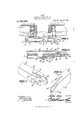
In the accompanying drawing:-Figure 1 shows in vertical longitudinal section, portions of a pair of railway vehicles to which the couplers forming the subject matter of this application have been attached, parts appearing in elevation; Fig. 2 is a horizontal section delineating the coupling head and its casing; Figs. 3 and 4 are perspective views of the head.
In the accompanying drawings, the numeral 1 indicates a car provided with a draw bar 2 constituting a support for the coupler forming the subject matter of this application.
In carrying out the present invention there is provided a box-like casing 3 located below the draw bar 2 and equipped with an upstanding lug which abuts against the lower face of the draw bar. U-bolts 16 or other suitable connecting elements unite the draw bar with the casing 3, the lugs 15, if desired being provided with lateral flanges 17 through which the U-bolts 16 pass.
In its sides, the casing 8 is provided with openings 4 defining shoulders 5. Disposed within the casing 3 is a slidably mounted head (i. A com ression spring 7 abuts against the end 0 the head 6 and against the rear end of the casing 3, the head 6 being equipped with projections 18 of any desired .sort which, coacting with the shoulder 5,
limit the outward movement of the head 6 under the action of the spring 7.
The head 6 is terminally bifurcated to form a tapered main arm 8, a tapered auxiliary arm 9, and a V-shaped seat 12 between the arms. The main arm 8 preferably is somewhat longer than the auxiliary arm 9. In the extremity of the arm 9 is formed a V-shapcd notch 10 defining pointed fingers 11. On the outer face of the main arm 8 there is a V-shapcd rib 14. The inner face of the main arm 8 preferably is provided with a resilient gasket 19. Formed in the interior of the head 6 are one or more passages 20, opening laterally, as indicated at 21, through the gasket 19. The rear ends of the passages 20 open as indicated at .23 laterally through the side wall of the head 6 and by means of suitable couplings 22 are connected with the fluid pressure pipes 25. It is to be understood that the head 6 may be provided with as many passages 20 as is considered expedient, the number of passages being regulated by the number of different fluid pressure lines of communication. The pipes 25 pass laterally out of one of the openings 4 in the casing 3, as will be obvious from Fig. 1.
The main arm 8 is shaped to be received 'in the seat 19. of an adjoining coupler and the V-shaped rib 14 on the one coupler is adapted to be received in the notch 10 of an adjoining coupler, the gaskets 19 on the couplers being forced into close and intimate contact, and a continuous drain pipe line being established through the mouths 21 of the passages 20, when a pair of couplers constructed in accordance with the present invention are brought togetherf Obviously, the springs 7 serve to thrust the heads 6 forwardly, and to maintain the heads on the couplers of a pair of cars in contact and in cooperating relation.
Having thus described the invention, what is claimed is In a coupler of the class described, a head terminally bifurcated to form tapered main and auxiliary arms and to form a tapered seat thcrebetwcen, the main arm being longer than the auxiliary arm. the auxiliary arm being terminally provided with a tapered notch, and the outer face of the main arm being provided with a tapered longitudinal rib, the main arm and the rib coacting with the seat to hold said mouths 10 being shaped to be received respectively in together.
the seat and in the notch of a hke coupler, In testimony that I claim the foregoing as the head hnving a )nssn e embodying a: my own, I have hereto ntiixed my signamouthwhich opens luterafily through the ture in the presence of two witnesses.
inner face of the main arm, the rib coacting JOHN ROY. with the notch to niine the mouths of two \Vitnesses: Y couplers when the same are brought into JOSEPH'B.1\ICCUE,
ooiipernting relation, and the main arm AXTAN DANIELSAN.
Copies 0! thin patent may be obtained for five cents each, by Midi-easing the Commissioner of Patents;
' Washington, D. O.
Priority Applications (1)
| Application Number | Priority Date | Filing Date | Title |
|---|---|---|---|
| US4382615A US1168426A (en) | 1915-08-05 | 1915-08-05 | Automatic air-hose coupling. |
Applications Claiming Priority (1)
| Application Number | Priority Date | Filing Date | Title |
|---|---|---|---|
| US4382615A US1168426A (en) | 1915-08-05 | 1915-08-05 | Automatic air-hose coupling. |
Publications (1)
| Publication Number | Publication Date |
|---|---|
| US1168426A true US1168426A (en) | 1916-01-18 |
Family
ID=3236443
Family Applications (1)
| Application Number | Title | Priority Date | Filing Date |
|---|---|---|---|
| US4382615A Expired - Lifetime US1168426A (en) | 1915-08-05 | 1915-08-05 | Automatic air-hose coupling. |
Country Status (1)
| Country | Link |
|---|---|
| US (1) | US1168426A (en) |
-
1915
- 1915-08-05 US US4382615A patent/US1168426A/en not_active Expired - Lifetime
Similar Documents
| Publication | Publication Date | Title |
|---|---|---|
| US1077417A (en) | Pipe-coupling. | |
| US968759A (en) | Guard for pipe-unions. | |
| US1168426A (en) | Automatic air-hose coupling. | |
| US1092673A (en) | Hose coupling or union. | |
| US1263574A (en) | Automatic hose-coupling. | |
| US693781A (en) | Dust-guard for hose-couplings. | |
| US2179854A (en) | Coupling unit | |
| US849466A (en) | Swivel check-valve. | |
| US755249A (en) | Pipe-coupling. | |
| US1092390A (en) | Flexible pipe-coupling. | |
| US223183A (en) | Improvement in couplings for hose and other pipes | |
| US123776A (en) | Improvement in couplings for st-eam or air brakes | |
| US881830A (en) | Hose-coupling. | |
| US1011727A (en) | Train-pipe coupling. | |
| US900132A (en) | Automatic air-hose coupling. | |
| US938183A (en) | Hose-coupling. | |
| US435800A (en) | Hose-coupling | |
| US1135893A (en) | Pipe-coupling. | |
| US1175600A (en) | Conduit-coupling. | |
| US443811A (en) | Coupling for railway-cars | |
| US1094115A (en) | Automatic line-coupling. | |
| US1095789A (en) | Pipe-coupling. | |
| US1089991A (en) | Car coupling and brake. | |
| US1820535A (en) | Hose coupler | |
| US999176A (en) | Train-pipe coupling. |