US11684113B2 - Footwear warming system and device - Google Patents
Footwear warming system and device Download PDFInfo
- Publication number
- US11684113B2 US11684113B2 US16/846,758 US202016846758A US11684113B2 US 11684113 B2 US11684113 B2 US 11684113B2 US 202016846758 A US202016846758 A US 202016846758A US 11684113 B2 US11684113 B2 US 11684113B2
- Authority
- US
- United States
- Prior art keywords
- footwear
- top segment
- heel portion
- spine
- retainer
- Prior art date
- Legal status (The legal status is an assumption and is not a legal conclusion. Google has not performed a legal analysis and makes no representation as to the accuracy of the status listed.)
- Active, expires
Links
- 238000010792 warming Methods 0.000 title claims abstract description 78
- 239000000463 material Substances 0.000 claims description 25
- 229920001084 poly(chloroprene) Polymers 0.000 claims description 7
- 239000011800 void material Substances 0.000 abstract description 6
- 239000007788 liquid Substances 0.000 abstract description 5
- XLYOFNOQVPJJNP-UHFFFAOYSA-N water Substances O XLYOFNOQVPJJNP-UHFFFAOYSA-N 0.000 abstract description 2
- 229920003023 plastic Polymers 0.000 description 8
- 230000000694 effects Effects 0.000 description 5
- 238000010438 heat treatment Methods 0.000 description 4
- 238000003780 insertion Methods 0.000 description 4
- 230000037431 insertion Effects 0.000 description 4
- 238000009413 insulation Methods 0.000 description 4
- 239000002184 metal Substances 0.000 description 4
- 238000000034 method Methods 0.000 description 4
- 238000001228 spectrum Methods 0.000 description 4
- 230000006378 damage Effects 0.000 description 1
- 230000003247 decreasing effect Effects 0.000 description 1
- 238000001035 drying Methods 0.000 description 1
- 239000012530 fluid Substances 0.000 description 1
- 210000003141 lower extremity Anatomy 0.000 description 1
- 230000037081 physical activity Effects 0.000 description 1
- 238000009877 rendering Methods 0.000 description 1
- 230000004083 survival effect Effects 0.000 description 1
Images


Classifications
-
- A—HUMAN NECESSITIES
- A43—FOOTWEAR
- A43B—CHARACTERISTIC FEATURES OF FOOTWEAR; PARTS OF FOOTWEAR
- A43B7/00—Footwear with health or hygienic arrangements
- A43B7/02—Footwear with health or hygienic arrangements with heating arrangements
-
- A—HUMAN NECESSITIES
- A43—FOOTWEAR
- A43B—CHARACTERISTIC FEATURES OF FOOTWEAR; PARTS OF FOOTWEAR
- A43B19/00—Shoe-shaped inserts; Inserts covering the instep
-
- A—HUMAN NECESSITIES
- A43—FOOTWEAR
- A43B—CHARACTERISTIC FEATURES OF FOOTWEAR; PARTS OF FOOTWEAR
- A43B5/00—Footwear for sporting purposes
- A43B5/04—Ski or like boots
- A43B5/0427—Ski or like boots characterised by type or construction details
-
- A—HUMAN NECESSITIES
- A43—FOOTWEAR
- A43B—CHARACTERISTIC FEATURES OF FOOTWEAR; PARTS OF FOOTWEAR
- A43B7/00—Footwear with health or hygienic arrangements
- A43B7/34—Footwear with health or hygienic arrangements with protection against heat or cold
-
- A—HUMAN NECESSITIES
- A43—FOOTWEAR
- A43B—CHARACTERISTIC FEATURES OF FOOTWEAR; PARTS OF FOOTWEAR
- A43B5/00—Footwear for sporting purposes
- A43B5/04—Ski or like boots
- A43B5/0405—Linings, paddings or insertions; Inner boots
Definitions
- the footwear warming device may be inserted into footwear and warm the footwear.
- the footwear warming system includes a device that can be inserted into the footwear.
- footwear Since the time when humans had to brave the cold weather, warm footwear has been key to comfort and survival. Footwear initially included fur and other types of insulation to help keep the wearer's feet warm because insulation helps keep feet warm in cold weather. However, when insulation is exposed to cold air (e.g., a foot is not inside the footwear) the footwear may be just as cold as footwear without insulation. Thus, footwear, particularly footwear used in cold weather activities, may be at an ambient cold temperature before being worn by a user, causing the user discomfort when installing footwear or during use of the footwear.
- a boot protects a larger portion of the lower extremities and therefore is a popular type of footwear for cold weather.
- the boot loses its main heat source. Ice and snow on the boot may melt in ambient conditions (e.g., indoors, or in other locations where people sleep overnight) causing the boot to get wet both internally and externally. This causes the boot to frequently be wet and cold when it is again needed. Few would argue that a boot is never more uncomfortable than when it is cold and wet in the morning.
- Boots of various kinds are used in many winter activities such as skiing and snowboarding. In many of these winter activities it is imperative that the boots are properly fit to the foot and that the boots, or boot inserts, are in good pliable condition. Winter activity boots are also prone to be coated in ice and snow and prone to not be warm enough to fit tightly to the foot. Due to the physical activity associated with the wearing of winter activity boots, comfort is a paramount concern to ensure that a user's foot is not injured (e.g., blisters or other foot ailments) due to a cold non-pliable boot.
- footwear warming devices which blow warm air into a boot, shoe, or other footwear.
- An opening of the footwear may be inserted over the warming device.
- the warming device is electrically powered to cause a filament within the warming device to increase in temperature while a fan blows air heated by the filament out of the device and into the footwear. This aids in warming and drying footwear.
- the relative heat level must be low so as to not catch the footwear on fire, which also results in a relatively long duration of time to fully dry and warm wet and cold footwear.
- this particular footwear warming device is not generally portable (batteries are typically an insufficient power source for such footwear warming devices) which means that only areas with electrical AC power can be used to warm footwear.
- Footwear warming devices typically cannot be used in vehicles which are, for example, on the way to a ski resort.
- a footwear warming device includes a body.
- the body has a top segment, a heel portion, and a toe projection.
- the body may extend vertically from the heel portion and horizontally from the heel portion toward the toe projection.
- the device further includes a retainer disposed about a circumference of the top segment of the body.
- the device further includes a cap disposed on the top segment of the body.
- the system includes a ski boot and a footwear warming device.
- the footwear warming device includes a body.
- the body has a top segment, a heel portion, and a toe projection.
- the body may extend vertically from the heel portion and horizontally from the heel portion toward the toe projection.
- the device further includes a retainer disposed about a circumference of the top segment of the body.
- the device further includes a cap disposed on the top segment of the body.
- FIG. 1 illustrates a side view of an embodiment of a footwear warming device.
- FIG. 2 illustrates a cross sectional view of an embodiment of a footwear warming system and device.
- FIG. 3 illustrates a top view of an embodiment of a footwear warming device.
- FIG. 4 illustrates a side view of an embodiment of a footwear warming device with inverted retainer.
- FIG. 1 illustrates a side view of an embodiment of a footwear warming device.
- Footwear warming device 100 may include cap 105 that attaches to top segment 130 of body 120 (also referred to as “body 120 ”). Cap 105 may be attached to the top segment 130 by a helical thread in a screw like manner. Cap 105 may also be secured to top segment 130 of body 120 by non-threaded friction. Cap 105 is generally made of a hard plastic material and opens to a hollow and watertight inside of body 120 . Footwear warming device 100 is made of material, such as neoprene or other similar materials, that may hold hot liquid securely with cap 105 secured to the top segment 130 of body 120 .
- Body 120 may be formed to a shape defined by a void within a footwear, such as a ski boot, so that the footwear warming device 100 contacts an entirety of an inside portion of the footwear.
- body 120 may be made of a form fitting material (e.g., neoprene) which fully fills a void in footwear.
- Body 120 may be generally angled and extend vertically from heel portion 135 with a toe projection that extends horizontally from heel portion 135 such that the angle between a bottom of heel 135 and spine 115 is up to 90° (e.g, perpendicular).
- an angle between a bottom of heel 135 and spine 115 is more preferably arranged in the range of 60° to 80° to allow body 120 to be more easily installed in and removed from footwear.
- the top segment 130 of body 120 may be encircled by a retainer 110 .
- Retainer 110 may fold down towards heel portion 135 of body 120 .
- Retainer 110 may be folded downwards over a top of a boot to hold footwear warming device 100 in place, especially when body 120 is filled with hot water.
- retainer 110 provides a bearing structure that rests on an opening of a boot, for example, to support footwear warming device 100 when installed within a boot such that footwear warming device 100 does not slide into the boot or fail to stay upright in the boot.
- Retainer 110 may also fold upwards to extend beyond the top segment 130 of body 120 to make footwear warming device 100 easily removable.
- Body 120 may optionally include finger holes or attached cordage through which fingers may be inserted to easily grip retainer 110 for removal of body 120 from footwear.
- Footwear warming device 100 may include a spine 115 that starts near cap 105 and goes down to heel portion 135 .
- Spine 115 may be implemented as a support that provides rigidity to body 120 such that spine 115 is more rigid than body 120 .
- the term rigidity encompasses a spectrum where more rigid elements of footwear warming device 100 are more capable of supporting their own weight than less rigid elements of footwear warming device 100 .
- Spine 115 may be more rigid than body 120 by forming spine 115 with metal, plastic, or other material, in a manner that makes spine 115 more able to maintain shape in an upright position.
- spine 115 bends around heel portion 135 towards toe projection 125 and ends at toe projection 125 .
- Spine 115 provides a rigid framework to facilitate insertion of footwear warming device 100 inside a boot, for example.
- Toe projection 125 fills a toe end of the footwear in which it is placed.
- FIG. 2 illustrates a cross sectional view of an embodiment of a footwear warming system and device 200 .
- Footwear warming device 200 may include cap 205 that attaches to top segment 230 of body 220 .
- Cap 205 may be attached to the top segment 230 by a helical thread in a screw like manner. Cap 205 may also be secured to top segment 230 of body 220 by non-threaded friction.
- Cap 205 is generally made of a hard plastic material and opens to a hollow inside of body 220 .
- Cap 205 may further incorporate a valve within body 220 which prevents a hot fluid from escaping (e.g., may be screwed into a screw in valve in the body).
- Footwear warming device 200 is made of material, such as neoprene or other similar materials, that may hold hot liquid securely with cap 205 secured to the top segment 230 of body 220 .
- Body 220 may be formed to a shape defined by a void within a boot, such as a ski boot, so that the footwear warming device 200 contacts an entirety of an inside portion of the boot.
- the top segment 230 of body 220 may be encircled by a retainer 210 .
- Retainer 210 may fold down towards heel portion 235 of body 220 .
- Retainer 210 may be folded downwards over a top of a boot to hold footwear warming device 200 in place.
- retainer 210 provides a bearing structure that rests on an opening of a boot, for example, to support footwear warming device 200 when installed within a boot such that footwear warming device 200 does not slide into the boot or fail to stay upright in the boot.
- Retainer 210 may also fold upwards to extend beyond the top segment 230 of body 220 to make footwear warming device 200 easily removable.
- Footwear warming device 200 may include a spine 215 that starts near cap 205 and extends down to heel portion 235 .
- Spine 215 may be implemented as a support that provides rigidity to body 220 such that spine 215 is more rigid than body 220 .
- the term rigidity encompasses a spectrum where more rigid elements of footwear warming device 200 are more capable of supporting their own weight than less rigid elements of footwear warming device 200 .
- Spine 215 may be more rigid than body 220 by forming spine 215 with metal, plastic, or other material, in a manner that makes spine 215 more able to maintain shape in an upright position.
- spine 215 bends around heel portion 235 towards toe projection 225 and ends at the toe portion.
- Spine 215 provides a rigid framework to facilitate insertion of footwear warming device 200 inside a boot, for example.
- Toe projection 225 fills a toe end of the footwear in which it is placed.
- FIG. 3 illustrates a top view of an embodiment of a footwear warming device 300 .
- Footwear warming device 300 may include cap 305 that attaches to top segment 330 of body 320 .
- Cap 305 may be attached to the top segment 330 by a helical thread in a screw like manner. Cap 305 may also be secured to top segment 330 of body 320 by non-threaded friction.
- Cap 305 is generally made of a hard plastic material and opens to a hollow inside of body 320 .
- Footwear warming device 300 is made as one or more pieces of watertight material, such as neoprene or other similar materials, that may hold hot liquid securely with cap 305 secured to the top segment 330 of body 320 .
- Body 320 may be formed to a shape defined by a void within a boot, such as a ski boot, so that the footwear warming device 300 contacts an entirety of an inside portion of the boot.
- the top segment 330 of body 320 may be encircled by a retainer 310 .
- Retainer 310 may fold down towards heel portion 335 of body 320 .
- Retainer 310 may be folded downwards over a top of a boot to hold footwear warming device 300 in place.
- retainer 310 provides a bearing structure that rests on an opening of a boot, for example, to support footwear warming device 300 when installed within a boot such that footwear warming device 300 does not slide into the boot or fail to stay upright in the boot.
- Retainer 310 may also fold upwards to extend beyond the top segment 330 of body 320 to make footwear warming device 300 easily removable.
- Footwear warming device 300 may include a spine 315 that starts near cap 305 and goes down to heel portion 335 .
- Spine 315 may be implemented as a support that provides rigidity to body 320 such that spine 315 is more rigid than body 320 .
- the term rigidity encompasses a spectrum where more rigid elements of footwear warming device 300 are more capable of supporting their own weight than less rigid elements of footwear warming device 300 .
- Spine 315 may be more rigid than body 320 by forming spine 315 with metal, plastic, or other material, in a manner that makes spine 315 more able to maintain shape in an upright position.
- spine 315 bends around heel portion 335 towards toe projection 325 and ends at or before the toe portion.
- Spine 315 provides a rigid framework to facilitate insertion of footwear warming device 300 inside a boot, for example.
- Toe projection 325 fills a toe end of the footwear in which it is placed.
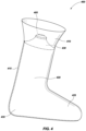
- FIG. 4 illustrates a side view of an embodiment of a footwear warming system and device with inverted retainer.
- Footwear warming device 400 may include cap 105 that attaches to top segment 430 of body 420 .
- Cap 405 may be attached to the top segment 430 by a helical thread in a screw like manner. Cap 405 may also be secured to top segment 430 of body 420 by non-threaded friction.
- Cap 405 is generally made of a hard plastic material and opens to a hollow inside of body 420 .
- Footwear warming device 400 is made of material, such as neoprene or other similar materials, that may hold hot liquid securely with cap 405 secured to the top segment 430 of body 420 .
- Body 420 may be formed to a shape defined by a void within a boot, such as a ski boot, so that the footwear warming device 400 contacts an entirety of an inside portion of the boot.
- the top segment 430 of body 420 may be encircled by a retainer 410 .
- Retainer 410 may fold down towards heel portion 435 of body 420 .
- Retainer 410 may be folded downwards over a top of a boot to hold footwear warming device 400 in place.
- retainer 410 provides a bearing structure that rests on an opening of a boot, for example, to support footwear warming device 400 when installed within a boot such that footwear warming device 400 does not slide into the boot or fail to stay upright in the boot.
- Retainer 410 may also fold upwards to extend beyond the top segment 430 of body 420 to make footwear warming device 400 easily removable.
- Footwear warming device 400 may include a spine 415 that starts near cap 405 and extends down to heel portion 435 .
- Spine 415 may be implemented as a support that provides rigidity to body 420 such that spine 415 is more rigid than body 420 .
- the term rigidity encompasses a spectrum where more rigid elements of footwear warming device 400 are more capable of supporting their own weight than less rigid elements of footwear warming device 400 .
- Spine 415 may be more rigid than body 420 by forming spine 415 with metal, plastic, or other material, in a manner that makes spine 415 more able to maintain shape in an upright position.
- spine 415 bends around heel portion 435 towards toe projection 425 and may end at the toe portion.
- Spine 415 provides a rigid framework to facilitate insertion of footwear warming device 400 inside a boot, for example.
- Toe projection 425 fills a toe end of the footwear in which it is placed.
Landscapes
- Health & Medical Sciences (AREA)
- General Health & Medical Sciences (AREA)
- Epidemiology (AREA)
- Public Health (AREA)
- Physical Education & Sports Medicine (AREA)
- Footwear And Its Accessory, Manufacturing Method And Apparatuses (AREA)
Abstract
Description
Claims (12)
Priority Applications (1)
| Application Number | Priority Date | Filing Date | Title |
|---|---|---|---|
| US16/846,758 US11684113B2 (en) | 2019-04-12 | 2020-04-13 | Footwear warming system and device |
Applications Claiming Priority (2)
| Application Number | Priority Date | Filing Date | Title |
|---|---|---|---|
| US201962833137P | 2019-04-12 | 2019-04-12 | |
| US16/846,758 US11684113B2 (en) | 2019-04-12 | 2020-04-13 | Footwear warming system and device |
Publications (2)
| Publication Number | Publication Date |
|---|---|
| US20200323303A1 US20200323303A1 (en) | 2020-10-15 |
| US11684113B2 true US11684113B2 (en) | 2023-06-27 |
Family
ID=72748414
Family Applications (1)
| Application Number | Title | Priority Date | Filing Date |
|---|---|---|---|
| US16/846,758 Active 2040-08-28 US11684113B2 (en) | 2019-04-12 | 2020-04-13 | Footwear warming system and device |
Country Status (1)
| Country | Link |
|---|---|
| US (1) | US11684113B2 (en) |
Citations (10)
| Publication number | Priority date | Publication date | Assignee | Title |
|---|---|---|---|---|
| US90197A (en) * | 1869-05-18 | Improved heating-shoe | ||
| GB190022071A (en) * | 1900-12-05 | 1901-02-23 | Walter Henry Duffin | Boot and Shoe Drier and Warmer. |
| US1199914A (en) * | 1916-03-06 | 1916-10-03 | Philip S Williams | Leg-warming boot. |
| US1257086A (en) * | 1917-04-03 | 1918-02-19 | Hart W Marcellus | Hot-water boot. |
| US1270666A (en) * | 1918-01-15 | 1918-06-25 | Edward Gouldar Smith | Shoe-drier. |
| US3823434A (en) * | 1973-04-23 | 1974-07-16 | B Krell | Shoe warmer |
| CN87205736U (en) * | 1987-03-27 | 1987-11-25 | 王斗 | Multipurpose hot water bag |
| CN2323736Y (en) * | 1997-05-13 | 1999-06-16 | 刘诒 | Shoe shape water bag shoe dryer |
| US20040010212A1 (en) * | 2002-04-01 | 2004-01-15 | Kuiper Hendrik Klaas | Therapeutic limb covering using hydrostatic pressure |
| US20050189344A1 (en) * | 2004-03-01 | 2005-09-01 | Chris Bachman | Boot/ski boot softener and warmer |
-
2020
- 2020-04-13 US US16/846,758 patent/US11684113B2/en active Active
Patent Citations (10)
| Publication number | Priority date | Publication date | Assignee | Title |
|---|---|---|---|---|
| US90197A (en) * | 1869-05-18 | Improved heating-shoe | ||
| GB190022071A (en) * | 1900-12-05 | 1901-02-23 | Walter Henry Duffin | Boot and Shoe Drier and Warmer. |
| US1199914A (en) * | 1916-03-06 | 1916-10-03 | Philip S Williams | Leg-warming boot. |
| US1257086A (en) * | 1917-04-03 | 1918-02-19 | Hart W Marcellus | Hot-water boot. |
| US1270666A (en) * | 1918-01-15 | 1918-06-25 | Edward Gouldar Smith | Shoe-drier. |
| US3823434A (en) * | 1973-04-23 | 1974-07-16 | B Krell | Shoe warmer |
| CN87205736U (en) * | 1987-03-27 | 1987-11-25 | 王斗 | Multipurpose hot water bag |
| CN2323736Y (en) * | 1997-05-13 | 1999-06-16 | 刘诒 | Shoe shape water bag shoe dryer |
| US20040010212A1 (en) * | 2002-04-01 | 2004-01-15 | Kuiper Hendrik Klaas | Therapeutic limb covering using hydrostatic pressure |
| US20050189344A1 (en) * | 2004-03-01 | 2005-09-01 | Chris Bachman | Boot/ski boot softener and warmer |
Non-Patent Citations (1)
| Title |
|---|
| HomeTop. HomeTop Premium Classic Rubber Hot Water Bottle, Great for Pain Relief, Hot and Cold Therapy. Retrieved from internet: http://www.amazon.com/HomeTop-Premium-Classic-Rubber-Therapy/dp/B00K3NZUPY/ref=sr_1_2?crid=23OAGATHL46BH&keywords=HomeTop%2BPremium%2BClassic%2BRubber%2BHot%2BWater%2BBottle% (Year: 2014). * |
Also Published As
| Publication number | Publication date |
|---|---|
| US20200323303A1 (en) | 2020-10-15 |
Similar Documents
| Publication | Publication Date | Title |
|---|---|---|
| US1257086A (en) | Hot-water boot. | |
| US3263679A (en) | Surgical foot cast and appliances therefor | |
| EP2838394B1 (en) | Wearable pedicure protection device | |
| US2703937A (en) | Ventilated boot | |
| US20100249685A1 (en) | Arch support wrap | |
| US20060201025A1 (en) | Heating insole | |
| US1199914A (en) | Leg-warming boot. | |
| EP3326481B1 (en) | Heating system for articles of footwear | |
| US11684113B2 (en) | Footwear warming system and device | |
| US20090054959A1 (en) | Therapeutic foot and leg warmer | |
| KR200449496Y1 (en) | shoes | |
| KR102478181B1 (en) | Fever shoe cover | |
| US20060248747A1 (en) | Heater for active wear boots | |
| JP2002209607A (en) | Insole inserted in shoes | |
| US7288110B1 (en) | Heater device for heating a user's hands and feet | |
| JP2009006043A (en) | Foot warmer | |
| KR20190000056U (en) | A shoes with a thermal insole and its thermal insole | |
| US20080052955A1 (en) | Waterproof Sock | |
| KR200370620Y1 (en) | Foot Heating Device | |
| JP4055743B2 (en) | Foot bath | |
| KR200489548Y1 (en) | Warming Shoes For Medical Needs Can Be Easy Putting On | |
| US20090260615A1 (en) | Warmer for Feet | |
| SK1442021U1 (en) | Thermotherapeutic device | |
| KR101784167B1 (en) | warmer shoes | |
| EP3991701A1 (en) | Thermotherapeutic device |
Legal Events
| Date | Code | Title | Description |
|---|---|---|---|
| AS | Assignment |
Owner name: MOUNTAIN VENTURE HOLDINGS, LLC, UTAH Free format text: ASSIGNMENT OF ASSIGNORS INTEREST;ASSIGNORS:BADGER, AUSTIN;BADGER, ROBERT JESSE TAYLOR;BADGER, JOHN;AND OTHERS;REEL/FRAME:052379/0934 Effective date: 20200413 |
|
| FEPP | Fee payment procedure |
Free format text: ENTITY STATUS SET TO UNDISCOUNTED (ORIGINAL EVENT CODE: BIG.); ENTITY STATUS OF PATENT OWNER: SMALL ENTITY |
|
| FEPP | Fee payment procedure |
Free format text: ENTITY STATUS SET TO SMALL (ORIGINAL EVENT CODE: SMAL); ENTITY STATUS OF PATENT OWNER: SMALL ENTITY |
|
| STPP | Information on status: patent application and granting procedure in general |
Free format text: APPLICATION DISPATCHED FROM PREEXAM, NOT YET DOCKETED |
|
| STPP | Information on status: patent application and granting procedure in general |
Free format text: DOCKETED NEW CASE - READY FOR EXAMINATION |
|
| STPP | Information on status: patent application and granting procedure in general |
Free format text: NON FINAL ACTION MAILED |
|
| STPP | Information on status: patent application and granting procedure in general |
Free format text: FINAL REJECTION MAILED |
|
| STPP | Information on status: patent application and granting procedure in general |
Free format text: DOCKETED NEW CASE - READY FOR EXAMINATION |
|
| STPP | Information on status: patent application and granting procedure in general |
Free format text: NON FINAL ACTION MAILED |
|
| STPP | Information on status: patent application and granting procedure in general |
Free format text: FINAL REJECTION MAILED |
|
| STCF | Information on status: patent grant |
Free format text: PATENTED CASE |