US11652261B2 - Cylindrical type secondary battery - Google Patents
Cylindrical type secondary battery Download PDFInfo
- Publication number
- US11652261B2 US11652261B2 US17/048,704 US201917048704A US11652261B2 US 11652261 B2 US11652261 B2 US 11652261B2 US 201917048704 A US201917048704 A US 201917048704A US 11652261 B2 US11652261 B2 US 11652261B2
- Authority
- US
- United States
- Prior art keywords
- separator
- metal layer
- electrode assembly
- tab
- negative electrode
- Prior art date
- Legal status (The legal status is an assumption and is not a legal conclusion. Google has not performed a legal analysis and makes no representation as to the accuracy of the status listed.)
- Active, expires
Links
Images


Classifications
-
- H—ELECTRICITY
- H01—ELECTRIC ELEMENTS
- H01M—PROCESSES OR MEANS, e.g. BATTERIES, FOR THE DIRECT CONVERSION OF CHEMICAL ENERGY INTO ELECTRICAL ENERGY
- H01M50/00—Constructional details or processes of manufacture of the non-active parts of electrochemical cells other than fuel cells, e.g. hybrid cells
- H01M50/50—Current conducting connections for cells or batteries
- H01M50/531—Electrode connections inside a battery casing
- H01M50/538—Connection of several leads or tabs of wound or folded electrode stacks
-
- H—ELECTRICITY
- H01—ELECTRIC ELEMENTS
- H01M—PROCESSES OR MEANS, e.g. BATTERIES, FOR THE DIRECT CONVERSION OF CHEMICAL ENERGY INTO ELECTRICAL ENERGY
- H01M50/00—Constructional details or processes of manufacture of the non-active parts of electrochemical cells other than fuel cells, e.g. hybrid cells
- H01M50/50—Current conducting connections for cells or batteries
- H01M50/531—Electrode connections inside a battery casing
- H01M50/533—Electrode connections inside a battery casing characterised by the shape of the leads or tabs
-
- H—ELECTRICITY
- H01—ELECTRIC ELEMENTS
- H01M—PROCESSES OR MEANS, e.g. BATTERIES, FOR THE DIRECT CONVERSION OF CHEMICAL ENERGY INTO ELECTRICAL ENERGY
- H01M10/00—Secondary cells; Manufacture thereof
- H01M10/04—Construction or manufacture in general
- H01M10/0422—Cells or battery with cylindrical casing
-
- H—ELECTRICITY
- H01—ELECTRIC ELEMENTS
- H01M—PROCESSES OR MEANS, e.g. BATTERIES, FOR THE DIRECT CONVERSION OF CHEMICAL ENERGY INTO ELECTRICAL ENERGY
- H01M10/00—Secondary cells; Manufacture thereof
- H01M10/04—Construction or manufacture in general
- H01M10/0431—Cells with wound or folded electrodes
-
- H—ELECTRICITY
- H01—ELECTRIC ELEMENTS
- H01M—PROCESSES OR MEANS, e.g. BATTERIES, FOR THE DIRECT CONVERSION OF CHEMICAL ENERGY INTO ELECTRICAL ENERGY
- H01M50/00—Constructional details or processes of manufacture of the non-active parts of electrochemical cells other than fuel cells, e.g. hybrid cells
- H01M50/40—Separators; Membranes; Diaphragms; Spacing elements inside cells
- H01M50/409—Separators, membranes or diaphragms characterised by the material
- H01M50/431—Inorganic material
-
- H—ELECTRICITY
- H01—ELECTRIC ELEMENTS
- H01M—PROCESSES OR MEANS, e.g. BATTERIES, FOR THE DIRECT CONVERSION OF CHEMICAL ENERGY INTO ELECTRICAL ENERGY
- H01M50/00—Constructional details or processes of manufacture of the non-active parts of electrochemical cells other than fuel cells, e.g. hybrid cells
- H01M50/40—Separators; Membranes; Diaphragms; Spacing elements inside cells
- H01M50/46—Separators, membranes or diaphragms characterised by their combination with electrodes
-
- H—ELECTRICITY
- H01—ELECTRIC ELEMENTS
- H01M—PROCESSES OR MEANS, e.g. BATTERIES, FOR THE DIRECT CONVERSION OF CHEMICAL ENERGY INTO ELECTRICAL ENERGY
- H01M50/00—Constructional details or processes of manufacture of the non-active parts of electrochemical cells other than fuel cells, e.g. hybrid cells
- H01M50/50—Current conducting connections for cells or batteries
- H01M50/531—Electrode connections inside a battery casing
- H01M50/536—Electrode connections inside a battery casing characterised by the method of fixing the leads to the electrodes, e.g. by welding
-
- H—ELECTRICITY
- H01—ELECTRIC ELEMENTS
- H01M—PROCESSES OR MEANS, e.g. BATTERIES, FOR THE DIRECT CONVERSION OF CHEMICAL ENERGY INTO ELECTRICAL ENERGY
- H01M50/00—Constructional details or processes of manufacture of the non-active parts of electrochemical cells other than fuel cells, e.g. hybrid cells
- H01M50/50—Current conducting connections for cells or batteries
- H01M50/572—Means for preventing undesired use or discharge
- H01M50/584—Means for preventing undesired use or discharge for preventing incorrect connections inside or outside the batteries
- H01M50/59—Means for preventing undesired use or discharge for preventing incorrect connections inside or outside the batteries characterised by the protection means
- H01M50/595—Tapes
-
- H—ELECTRICITY
- H01—ELECTRIC ELEMENTS
- H01M—PROCESSES OR MEANS, e.g. BATTERIES, FOR THE DIRECT CONVERSION OF CHEMICAL ENERGY INTO ELECTRICAL ENERGY
- H01M2220/00—Batteries for particular applications
- H01M2220/20—Batteries in motive systems, e.g. vehicle, ship, plane
-
- Y—GENERAL TAGGING OF NEW TECHNOLOGICAL DEVELOPMENTS; GENERAL TAGGING OF CROSS-SECTIONAL TECHNOLOGIES SPANNING OVER SEVERAL SECTIONS OF THE IPC; TECHNICAL SUBJECTS COVERED BY FORMER USPC CROSS-REFERENCE ART COLLECTIONS [XRACs] AND DIGESTS
- Y02—TECHNOLOGIES OR APPLICATIONS FOR MITIGATION OR ADAPTATION AGAINST CLIMATE CHANGE
- Y02E—REDUCTION OF GREENHOUSE GAS [GHG] EMISSIONS, RELATED TO ENERGY GENERATION, TRANSMISSION OR DISTRIBUTION
- Y02E60/00—Enabling technologies; Technologies with a potential or indirect contribution to GHG emissions mitigation
- Y02E60/10—Energy storage using batteries
-
- Y—GENERAL TAGGING OF NEW TECHNOLOGICAL DEVELOPMENTS; GENERAL TAGGING OF CROSS-SECTIONAL TECHNOLOGIES SPANNING OVER SEVERAL SECTIONS OF THE IPC; TECHNICAL SUBJECTS COVERED BY FORMER USPC CROSS-REFERENCE ART COLLECTIONS [XRACs] AND DIGESTS
- Y02—TECHNOLOGIES OR APPLICATIONS FOR MITIGATION OR ADAPTATION AGAINST CLIMATE CHANGE
- Y02P—CLIMATE CHANGE MITIGATION TECHNOLOGIES IN THE PRODUCTION OR PROCESSING OF GOODS
- Y02P70/00—Climate change mitigation technologies in the production process for final industrial or consumer products
- Y02P70/50—Manufacturing or production processes characterised by the final manufactured product
Definitions
- the present invention relates to a cylindrical type secondary battery, and more particularly, to a cylindrical type secondary battery having an improved heat radiation function.
- Such a secondary battery includes, for example, a nickel cadmium battery, a nickel hydrogen battery, a nickel zinc battery, and a lithium secondary battery.
- the lithium secondary battery compared with a nickel-based secondary battery, since memory effects hardly occur, is widely used in high-technology electronic devices due to its advantages such as free charging and discharging, a very low self-discharge rate, a high operating voltage, a high energy density per unit weight, and the like.
- a lithium secondary battery has a structure in which unit cells configured of a positive electrode, a negative electrode, and a separator interposed therebetween are stacked or wound, it is embedded in a case of a metal can or laminate sheet, and an electrolyte solution is injected or impregnated therein.
- An electrode assembly of a positive electrode/separator/negative electrode structure configuring the secondary battery is mainly divided into a jelly roll type (wound type) and a stack type (stacked type) according to its structure.
- the jelly roll type is a structure obtained by interposing a separator between long sheet-type positive and negative electrodes coated with an active material and then winding it
- a stack type is a structure in which a plurality of positive and negative electrodes with a predetermined size are sequentially stacked in a state in which a separator is interposed therebetween.
- the present invention has been made in an effort to provide a cylindrical type secondary battery that may reduce resistance and increase stability of a battery cell.
- An electrode assembly includes: a negative electrode sheet, a positive electrode sheet, an electrode tab attached to one of the negative electrode sheet or the positive electrode sheet, a separator defining at an outermost side of the electrode assembly and a metal layer disposed between the electrode tab and the separator.
- the metal layer may include an adhesive material.
- the electrode tab may include a tab body attached to the one of the negative electrode sheet or the positive electrode sheet and a protrusion extending from one end of the electrode assembly, and the protrusion may be welded to the metal layer.
- the tab body and the metal layer may be connected by the adhesive material.
- the electrode tab may be a negative electrode tab.
- the metal layer may be a plate shaped copper foil.
- the electrode tab and the metal layer may overlap at an end portion of the separator.
- the metal layer may be connected to the electrode tab and the separator by an adhesive layer formed of the adhesive material.
- the electrode assembly may further include an insulating tape fixing a boundary portion of the separator at an end of the separator.
- the insulating tape and the metal layer may not overlap.
- a device includes a cylindrical type secondary battery having the above-described electrode assembly as a power source.
- the jelly roll type of electrode assembly is fixed and a thickness of the negative electrode tab is increased to reduce resistance and diffuse heat generated when a high current is applied or when a short circuit occurs at the outside, thus it is possible to implement a cylindrical type secondary battery that may have increased stability and lifespan of a battery cell.
- FIG. 1 is an exploded perspective view showing a state before an electrode assembly according to an embodiment of the present invention is wound.
- FIG. 2 is a perspective view showing a state after the electrode assembly of FIG. 1 is wound.
- FIG. 3 is an enlarged partial plan view of a portion A of FIG. 2 .
- FIG. 4 is a view of the portion A viewed from an X direction of FIG. 2 .
- FIG. 5 is a partial plan view of an electrode assembly according to another embodiment of the present invention.
- FIG. 6 is a partial plan view of an electrode assembly according to another embodiment of the present invention.
- FIG. 7 is a cross-sectional view taken along line Y-Y′ of FIG. 6 .
- FIG. 8 is a perspective view showing an electrode assembly according to another embodiment of the present invention.
- the phrase “in a plan view” means viewing a target portion from the top
- the phrase “in a cross-sectional view” means viewing a cross-section formed by vertically cutting a target portion from the side.
- FIG. 1 is an exploded perspective view showing a state before an electrode assembly according to an embodiment of the present invention is wound.
- FIG. 2 is a perspective view showing a state after the electrode assembly of FIG. 1 is wound.
- a secondary battery includes an electrode assembly 100 including a negative electrode sheet 110 , a positive electrode sheet 120 , and a separator 130 .
- the electrode assembly 100 may have a jelly roll type of structure.
- the separator 130 is interposed between the negative electrode sheet 110 and the positive electrode sheet 120 , and may have a jelly roll structure formed in an order of the positive electrode sheet 120 , the separator 130 , and the negative electrode sheet 110 along a direction from a central portion thereof to the outside thereof, and one or more of the structures may be present.
- a separator 130 s is disposed at the outermost side of the electrode assembly 100 .
- Electrode tabs may be attached to the positive electrode sheet 120 and the negative electrode sheet 110 , respectively, and the electrode tabs include a negative electrode tab 140 attached to the negative electrode sheet 110 and a positive electrode tab 160 attached to the positive electrode sheet 120 .
- the negative electrode sheet 110 may be disposed adjacent to the separator 130 inside the separator 130 s disposed at the outermost portion of the electrode assembly 100 , and the negative electrode tab 140 may be attached to the negative electrode sheet 110 .
- a metal layer 145 may be formed between the negative electrode tab 140 and the separator 130 s disposed at the outermost side.
- the metal layer 145 contains an adhesive material.
- the adhesive material may contain an acrylic material.
- the metal layer 145 may be formed of a copper foil with a plate shape.
- the negative electrode tab 140 and the metal layer 145 may be disposed to overlap each other at an end portion of the separator 130 s disposed at the outermost side. In this case, the metal layer 145 may contact the negative electrode tab 140 and the separator 130 s disposed at the outermost side.
- the metal layer 145 may include a separate adhesive layer formed of an adhesive material to contact the negative electrode tab 140 and the separator 130 s through the adhesive layer.
- one or more positive and negative electrode tabs may be additionally attached for a high power model.
- the secondary battery of the high output and high capacity model when a large current flows within a short time due to high rate discharge, overcharge, an external short circuit, etc., a large amount of heat is generated in the electrode tab, particularly in the negative electrode tab 140 due to a current concentration. Since charging or discharging is continuously and repeatedly generated by an electrochemical reaction in the secondary battery, when the secondary battery becomes high in capacity, heat generation due to the charging and discharging is dramatically increased. Due to the heat generation, the separator 130 may be damaged to lead to an internal short circuit, which may lead to temperature variation inside the secondary battery, thereby resulting in deterioration of the secondary battery.
- the negative electrode tab 140 having particularly high resistance among internal components of the secondary battery, heat generation thereof occurs most.
- a high current is applied to the battery cell, and thus, it is important to lower heat and temperature of the electrode tab because heat of the jelly roll type of electrode assembly generated at this time may be radiated in a battery case formed of a metal material through the electrode tab.
- the metal layer 145 according to the present embodiment described above may effectively release heat generated in the negative electrode tab 140 to solve the heat generation problem.
- the metal layer 145 contains an adhesive material, the end portion of the separator 130 s disposed at the outermost side is fixed to maintain a shape of the electrode assembly 100 having a jelly roll type of structure, thereby preventing the electrode assembly 100 from being released by internal stress.
- the metal layer 145 containing copper has an effect of increasing a thickness of the negative electrode tab 140 , a concentration of heat may be reduced by reducing resistance thereof.
- the positive electrode sheet 120 may be disposed at the position at which the negative electrode sheet 110 is formed, and in this case, the negative electrode sheet 110 may be disposed at the position of the positive electrode sheet 120 , so that a jelly roll structure may be formed in the order of the negative electrode sheet 110 , the separator 130 , and the positive electrode sheet 120 along a direction from a central position toward the outside.
- the positive electrode sheet 120 may be disposed adjacent to the separator 130 inside the separator 130 s disposed at the outermost side.
- the metal layer 145 may be an aluminum foil and may contain an adhesive material.
- FIG. 3 is an enlarged partial plan view of a portion A of FIG. 2 .
- FIG. 4 is a view of the portion A viewed from an X direction of FIG. 2 .
- the negative electrode tab 140 is attached on the negative electrode sheet 110 disposed directly inside the outermost separator 130 s .
- the negative electrode tab 140 may have a plate shape, and includes a protrusion 140 p extending from one end of the electrode assembly 100 .
- the metal layer 145 may be formed directly on the negative electrode tab 140 , and the metal layer 145 may be formed to cover left and right surfaces of the negative electrode tab 140 .
- the metal layer 145 may extend not only on a tab body of the negative electrode tab 140 , but also on the protrusion 140 p.
- the metal layer 145 may be bonded to the negative electrode tab 140 and the outermost separator 130 s disposed on upper and lower surfaces of the metal layer 145 by the adhesive material included in the metal layer 145 .
- the end portion of the outermost separator 130 s is fixed by the metal layer 145 containing the adhesive material to maintain a shape of the electrode assembly 100 having a jelly roll type of structure, thereby preventing the electrode assembly 100 from being released by internal stress.
- the electrode assembly 100 according to the present embodiment described above may be accommodated in a battery case (not shown) such as a metal can to form a cylindrical type secondary battery.
- a battery case such as a metal can to form a cylindrical type secondary battery.
- FIG. 5 is a partial plan view of an electrode assembly according to another embodiment of the present invention.
- FIG. 5 is substantially the same as the embodiment described with reference to FIG. 3 and FIG. 4 , except that the metal layer 145 is not formed on the protrusion 140 p of the negative electrode tab 140 , but may be formed only on the tab body of of the negative electrode tab.
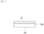
- FIG. 6 is a partial plan view of an electrode assembly according to another embodiment of the present invention.
- FIG. 7 is a cross-sectional view taken along line Y-Y′ of FIG. 6 .
- FIG. 6 and FIG. 7 is substantially the same as the embodiment of FIG. 3 and FIG. 4 described above. Only differences therebetween will be described below. Except for the differences, the contents described in the embodiment of FIG. 3 and FIG. 4 are applicable to the present embodiment.
- the tab body of the negative electrode tab 140 and the metal layer 145 may be adhered to each other by an adhesive material included in the metal layer 145 in the tab body of the negative electrode tab 140 .
- the protrusion 147 of the metal layer 145 and the protrusion 140 p of the negative electrode tab 140 may be welded to each other to form the welding portion 140 s and combined.
- the negative electrode tab 140 and the metal layer 145 are combined to be able to increase capacity. Due to the heat generation, a temperature cut-off is reached, which may result in early voltage cut-off without using sufficient capacity.
- the negative electrode tab 140 and the metal layer 145 are combined through the welding process according to the present embodiment to increase the heat radiation effect, the early voltage cut-off may be prevented, resulting in an improvement in capacity.
- FIG. 8 is a perspective view showing an electrode assembly according to another embodiment of the present invention.
- an insulating tape 300 attached to an outer circumferential surface of the electrode assembly 100 included in the secondary battery according to the embodiment described with reference to FIG. 3 and FIG. 4 is included.
- the insulating tape 300 may serve as a finishing tape at the end of the outermost separator 130 s . That is, a boundary portion 150 with the separator 130 may be fixed at the end of the outermost separator 130 s .
- the insulating tape 300 may be disposed at the end of the outermost separator 130 s so as to not overlap the metal layer 145 .
- the insulating tape 300 may include a thermosetting resin selected from a group of polyvinyl chloride, a mixture of a nitrile rubber and a phenol resin, an epoxy resin, polyurethane, and combinations thereof.
- the shape of the electrode assembly 100 having the jelly roll type of structure can be more stably maintained.
- the secondary battery described above may be applied to various devices. These devices may be applied to a transportation apparatus such as an electric bicycle, an electric vehicle, a hybrid vehicle, and the like, but are not limited thereto, and may be applied to various devices that can use the secondary battery.
- a transportation apparatus such as an electric bicycle, an electric vehicle, a hybrid vehicle, and the like, but are not limited thereto, and may be applied to various devices that can use the secondary battery.
Abstract
Description
- 130, 130 s: separator
- 140: negative electrode tab
- 140 p: protrusion
- 145: metal layer
Claims (10)
Applications Claiming Priority (3)
| Application Number | Priority Date | Filing Date | Title |
|---|---|---|---|
| KR10-2018-0148564 | 2018-11-27 | ||
| KR1020180148564A KR102459970B1 (en) | 2018-11-27 | 2018-11-27 | Cylindrical type secondary battery |
| PCT/KR2019/010227 WO2020111444A1 (en) | 2018-11-27 | 2019-08-12 | Cylindrical secondary battery |
Publications (2)
| Publication Number | Publication Date |
|---|---|
| US20210159573A1 US20210159573A1 (en) | 2021-05-27 |
| US11652261B2 true US11652261B2 (en) | 2023-05-16 |
Family
ID=70853738
Family Applications (1)
| Application Number | Title | Priority Date | Filing Date |
|---|---|---|---|
| US17/048,704 Active 2040-06-06 US11652261B2 (en) | 2018-11-27 | 2019-08-12 | Cylindrical type secondary battery |
Country Status (9)
| Country | Link |
|---|---|
| US (1) | US11652261B2 (en) |
| EP (1) | EP3771010B1 (en) |
| JP (2) | JP7451863B2 (en) |
| KR (1) | KR102459970B1 (en) |
| CN (1) | CN112005416A (en) |
| ES (1) | ES2954481T3 (en) |
| HU (1) | HUE062698T2 (en) |
| PL (1) | PL3771010T3 (en) |
| WO (1) | WO2020111444A1 (en) |
Citations (26)
| Publication number | Priority date | Publication date | Assignee | Title |
|---|---|---|---|---|
| JPS61218058A (en) | 1985-03-25 | 1986-09-27 | Fuji Elelctrochem Co Ltd | Battery |
| JPH1126008A (en) | 1997-06-30 | 1999-01-29 | Sanyo Electric Co Ltd | Electrode structure of battery |
| JP2000150306A (en) | 1998-11-12 | 2000-05-30 | Toyota Motor Corp | Current collecting system of battery or capacitor |
| JP2002319410A (en) | 2001-04-19 | 2002-10-31 | Mitsubishi Materials Corp | Alkaline secondary battery electrode and alkaline secondary battery using the same |
| KR100509606B1 (en) | 2003-02-19 | 2005-08-22 | 삼성에스디아이 주식회사 | Jelly-roll type battery unit and winding method thereof and lithum secondary battery using the same |
| KR20060124036A (en) | 2005-05-30 | 2006-12-05 | 삼성에스디아이 주식회사 | Composite material tape for lithium secondary battery and lithium secondary battery using the same |
| KR20080057629A (en) | 2006-12-20 | 2008-06-25 | 삼성에스디아이 주식회사 | Electorde assembly and cylinder type secondary battery using the same |
| KR20090027314A (en) | 2007-09-12 | 2009-03-17 | 주식회사 엘지화학 | Secondary battery of improved stability by both sides adhesive tape |
| JP2009076301A (en) | 2007-09-20 | 2009-04-09 | Nec Tokin Corp | Nonaqueous electrolyte secondary battery |
| KR20090064757A (en) * | 2007-12-17 | 2009-06-22 | 주식회사 엘지화학 | Pouch type secondary battery |
| WO2009111744A2 (en) | 2008-03-07 | 2009-09-11 | Mobius Power, Inc. | Electrochemical cells with tabs |
| KR20090132925A (en) | 2008-06-23 | 2009-12-31 | 삼성에스디아이 주식회사 | Electrode assembly and lithium secondary battery with the same |
| US20100215996A1 (en) * | 2009-02-24 | 2010-08-26 | Eveready Battery Company, Inc. | Closure Assembly for Electrochemical Cells |
| JP2010192462A (en) | 2004-09-22 | 2010-09-02 | Samsung Sdi Co Ltd | Lithium secondary battery |
| US20100233525A1 (en) | 2009-03-10 | 2010-09-16 | Sanyo Electric Co., Ltd. | Nonaqueous electrolyte secondary battery |
| WO2014003382A1 (en) | 2012-06-25 | 2014-01-03 | 에스케이이노베이션 주식회사 | Battery pack |
| US20140141338A1 (en) | 2012-11-19 | 2014-05-22 | Samsung Sdi Co., Ltd. | Rechargeable lithium battery |
| KR20160005421A (en) | 2014-07-07 | 2016-01-15 | 주식회사 엘지화학 | Battery Cell Having Separation Film of Suppressed Thermal Shrinkage |
| JP2016122610A (en) | 2014-12-25 | 2016-07-07 | 株式会社Gsユアサ | Power storage element |
| JP2016146357A (en) | 2015-08-05 | 2016-08-12 | ソニー株式会社 | Battery and battery pack, electronic apparatus, electric vehicle, power storage device, and electric power system |
| US20160248071A1 (en) | 2013-09-27 | 2016-08-25 | Lg Chem, Ltd. | Secondary battery with electrode tab having low resistance |
| WO2016168715A1 (en) | 2015-04-15 | 2016-10-20 | Optodot Corporation | Coated stacks for batteries and related manufacturing methods |
| KR20170101632A (en) | 2016-02-29 | 2017-09-06 | 주식회사 엘지화학 | An electrode assembly with enhanced heat emission properties |
| JP2017216160A (en) | 2016-05-31 | 2017-12-07 | パナソニックIpマネジメント株式会社 | Nonaqueous electrolyte secondary battery |
| JP2018060599A (en) | 2016-09-30 | 2018-04-12 | 日立オートモティブシステムズ株式会社 | Square secondary battery |
| US20180269458A1 (en) | 2015-12-14 | 2018-09-20 | Lg Chem, Ltd. | Electrode assembly having indented portion formed on electrode plate, and secondary battery including same |
Family Cites Families (6)
| Publication number | Priority date | Publication date | Assignee | Title |
|---|---|---|---|---|
| JP4052537B2 (en) * | 1998-07-10 | 2008-02-27 | 日立マクセル株式会社 | Non-aqueous secondary battery |
| KR100998846B1 (en) * | 2007-11-21 | 2010-12-08 | 주식회사 엘지화학 | Battery Cell of Excellent Heat Dissipation Property and Middle or Large-sized Battery Module Employed with the Same |
| JP5258970B2 (en) | 2009-09-03 | 2013-08-07 | 三菱電機株式会社 | Flat wound power storage device cell and flat wound power storage device module |
| JP6008981B2 (en) * | 2012-02-07 | 2016-10-19 | エルジー・ケム・リミテッド | Secondary battery with new structure |
| US9466823B2 (en) * | 2013-02-28 | 2016-10-11 | Samsung Sdi Co., Ltd. | Rechargeable battery |
| CN206332096U (en) * | 2016-11-04 | 2017-07-14 | 赣州壹凌科技有限公司 | A kind of lithium battery |
-
2018
- 2018-11-27 KR KR1020180148564A patent/KR102459970B1/en active IP Right Grant
-
2019
- 2019-08-12 EP EP19890910.3A patent/EP3771010B1/en active Active
- 2019-08-12 CN CN201980027326.4A patent/CN112005416A/en active Pending
- 2019-08-12 ES ES19890910T patent/ES2954481T3/en active Active
- 2019-08-12 HU HUE19890910A patent/HUE062698T2/en unknown
- 2019-08-12 PL PL19890910.3T patent/PL3771010T3/en unknown
- 2019-08-12 US US17/048,704 patent/US11652261B2/en active Active
- 2019-08-12 WO PCT/KR2019/010227 patent/WO2020111444A1/en unknown
- 2019-08-12 JP JP2020554893A patent/JP7451863B2/en active Active
-
2023
- 2023-02-22 JP JP2023026745A patent/JP2023062175A/en active Pending
Patent Citations (35)
| Publication number | Priority date | Publication date | Assignee | Title |
|---|---|---|---|---|
| JPS61218058A (en) | 1985-03-25 | 1986-09-27 | Fuji Elelctrochem Co Ltd | Battery |
| JPH1126008A (en) | 1997-06-30 | 1999-01-29 | Sanyo Electric Co Ltd | Electrode structure of battery |
| JP2000150306A (en) | 1998-11-12 | 2000-05-30 | Toyota Motor Corp | Current collecting system of battery or capacitor |
| JP2002319410A (en) | 2001-04-19 | 2002-10-31 | Mitsubishi Materials Corp | Alkaline secondary battery electrode and alkaline secondary battery using the same |
| KR100509606B1 (en) | 2003-02-19 | 2005-08-22 | 삼성에스디아이 주식회사 | Jelly-roll type battery unit and winding method thereof and lithum secondary battery using the same |
| US9299970B2 (en) | 2003-02-19 | 2016-03-29 | Samsung Sdi Co., Ltd. | Jelly-roll type battery unit and winding method thereof and lithium secondary battery comprising the same |
| US8734985B2 (en) | 2003-02-19 | 2014-05-27 | Samsung Sdi Co., Ltd. | Jelly-roll type battery unit and winding method thereof and lithium secondary battery comprising the same |
| JP2010192462A (en) | 2004-09-22 | 2010-09-02 | Samsung Sdi Co Ltd | Lithium secondary battery |
| US20120156564A1 (en) | 2004-09-22 | 2012-06-21 | Cheon Soo Kim | Composite material tape for lithium secondary battery and lithium secondary battery using the same |
| KR20060124036A (en) | 2005-05-30 | 2006-12-05 | 삼성에스디아이 주식회사 | Composite material tape for lithium secondary battery and lithium secondary battery using the same |
| KR20080057629A (en) | 2006-12-20 | 2008-06-25 | 삼성에스디아이 주식회사 | Electorde assembly and cylinder type secondary battery using the same |
| KR20090027314A (en) | 2007-09-12 | 2009-03-17 | 주식회사 엘지화학 | Secondary battery of improved stability by both sides adhesive tape |
| JP2009076301A (en) | 2007-09-20 | 2009-04-09 | Nec Tokin Corp | Nonaqueous electrolyte secondary battery |
| KR101089161B1 (en) | 2007-12-17 | 2011-12-02 | 주식회사 엘지화학 | Pouch type Secondary battery |
| KR20090064757A (en) * | 2007-12-17 | 2009-06-22 | 주식회사 엘지화학 | Pouch type secondary battery |
| WO2009111744A2 (en) | 2008-03-07 | 2009-09-11 | Mobius Power, Inc. | Electrochemical cells with tabs |
| US9048489B2 (en) | 2008-06-23 | 2015-06-02 | Samsung Sdi Co., Ltd. | Electrode assembly and lithium secondary battery using the same |
| KR20090132925A (en) | 2008-06-23 | 2009-12-31 | 삼성에스디아이 주식회사 | Electrode assembly and lithium secondary battery with the same |
| US20100215996A1 (en) * | 2009-02-24 | 2010-08-26 | Eveready Battery Company, Inc. | Closure Assembly for Electrochemical Cells |
| KR20100102059A (en) | 2009-03-10 | 2010-09-20 | 산요덴키가부시키가이샤 | Non-aqueous electrolyte secondary battery |
| US20100233525A1 (en) | 2009-03-10 | 2010-09-16 | Sanyo Electric Co., Ltd. | Nonaqueous electrolyte secondary battery |
| WO2014003382A1 (en) | 2012-06-25 | 2014-01-03 | 에스케이이노베이션 주식회사 | Battery pack |
| US20140141338A1 (en) | 2012-11-19 | 2014-05-22 | Samsung Sdi Co., Ltd. | Rechargeable lithium battery |
| KR20140064168A (en) | 2012-11-19 | 2014-05-28 | 삼성에스디아이 주식회사 | Rechargeable lithium battery |
| US20160248071A1 (en) | 2013-09-27 | 2016-08-25 | Lg Chem, Ltd. | Secondary battery with electrode tab having low resistance |
| JP2016536770A (en) | 2013-09-27 | 2016-11-24 | エルジー・ケム・リミテッド | Secondary battery with low resistance electrode tab |
| KR20160005421A (en) | 2014-07-07 | 2016-01-15 | 주식회사 엘지화학 | Battery Cell Having Separation Film of Suppressed Thermal Shrinkage |
| JP2016122610A (en) | 2014-12-25 | 2016-07-07 | 株式会社Gsユアサ | Power storage element |
| WO2016168715A1 (en) | 2015-04-15 | 2016-10-20 | Optodot Corporation | Coated stacks for batteries and related manufacturing methods |
| JP2016146357A (en) | 2015-08-05 | 2016-08-12 | ソニー株式会社 | Battery and battery pack, electronic apparatus, electric vehicle, power storage device, and electric power system |
| US20180269458A1 (en) | 2015-12-14 | 2018-09-20 | Lg Chem, Ltd. | Electrode assembly having indented portion formed on electrode plate, and secondary battery including same |
| JP2018534737A (en) | 2015-12-14 | 2018-11-22 | エルジー・ケム・リミテッド | Electrode assembly in which bay portion is formed in electrode plate and secondary battery including the same |
| KR20170101632A (en) | 2016-02-29 | 2017-09-06 | 주식회사 엘지화학 | An electrode assembly with enhanced heat emission properties |
| JP2017216160A (en) | 2016-05-31 | 2017-12-07 | パナソニックIpマネジメント株式会社 | Nonaqueous electrolyte secondary battery |
| JP2018060599A (en) | 2016-09-30 | 2018-04-12 | 日立オートモティブシステムズ株式会社 | Square secondary battery |
Non-Patent Citations (3)
| Title |
|---|
| Extended European Search Report for European Application No. 19890910.3, dated Jul. 21, 2021. |
| International Search Report issued in PCT/KR2019/010227 (PCT/ISA/210), dated Dec. 2, 2019. |
| Machine Translation of: KR 10-2009-0064757, Han et al., Jun. 22, 2009. * |
Also Published As
| Publication number | Publication date |
|---|---|
| WO2020111444A1 (en) | 2020-06-04 |
| KR20200062767A (en) | 2020-06-04 |
| ES2954481T3 (en) | 2023-11-22 |
| JP2021518039A (en) | 2021-07-29 |
| CN112005416A (en) | 2020-11-27 |
| JP7451863B2 (en) | 2024-03-19 |
| PL3771010T3 (en) | 2023-10-23 |
| EP3771010A4 (en) | 2021-08-18 |
| HUE062698T2 (en) | 2023-11-28 |
| EP3771010B1 (en) | 2023-07-19 |
| JP2023062175A (en) | 2023-05-02 |
| KR102459970B1 (en) | 2022-10-26 |
| EP3771010A1 (en) | 2021-01-27 |
| US20210159573A1 (en) | 2021-05-27 |
Similar Documents
| Publication | Publication Date | Title |
|---|---|---|
| JP5113219B2 (en) | Secondary battery | |
| US7122271B2 (en) | Battery unit and lithium secondary battery employing the same | |
| US10056577B2 (en) | Battery cell of novel structure | |
| US9209493B2 (en) | Battery pack | |
| US11495847B2 (en) | Secondary battery and device including the same | |
| KR20220030627A (en) | Secondary battery and device including the same | |
| US9012070B2 (en) | Secondary battery | |
| US11652261B2 (en) | Cylindrical type secondary battery | |
| US11728534B2 (en) | Electrode assembly and rechargeable battery including the same | |
| US20200259222A1 (en) | Secondary battery | |
| US20200343519A1 (en) | Electrode Assembly with Improved Connection Between Electrode Tabs | |
| KR101792578B1 (en) | Battery Cell Having modified Lead Film | |
| US20230178828A1 (en) | Battery Cell and Battery Module Including the Same | |
| KR20220034533A (en) | Secondary battery and device including the same | |
| KR20230133570A (en) | Secondary battery and battery module including the same | |
| KR20230021335A (en) | Electrode assembly and secondary battery including the same | |
| KR20220030626A (en) | Secondary battery and device including the same | |
| KR20230037861A (en) | Secondary battery and battery module including the same | |
| KR20220061552A (en) | Secondary battery and device including the same |
Legal Events
| Date | Code | Title | Description |
|---|---|---|---|
| FEPP | Fee payment procedure |
Free format text: ENTITY STATUS SET TO UNDISCOUNTED (ORIGINAL EVENT CODE: BIG.); ENTITY STATUS OF PATENT OWNER: LARGE ENTITY |
|
| AS | Assignment |
Owner name: LG CHEM, LTD., KOREA, REPUBLIC OF Free format text: ASSIGNMENT OF ASSIGNORS INTEREST;ASSIGNORS:KIM, JEEEUN;KIM, NAMWON;RYU, DUK HYUN;REEL/FRAME:054135/0610 Effective date: 20200929 |
|
| STPP | Information on status: patent application and granting procedure in general |
Free format text: APPLICATION DISPATCHED FROM PREEXAM, NOT YET DOCKETED |
|
| STPP | Information on status: patent application and granting procedure in general |
Free format text: DOCKETED NEW CASE - READY FOR EXAMINATION |
|
| AS | Assignment |
Owner name: LG ENERGY SOLUTION, LTD., KOREA, REPUBLIC OF Free format text: ASSIGNMENT OF ASSIGNORS INTEREST;ASSIGNOR:LG CHEM, LTD.;REEL/FRAME:058295/0068 Effective date: 20211027 |
|
| STPP | Information on status: patent application and granting procedure in general |
Free format text: NON FINAL ACTION MAILED |
|
| STCF | Information on status: patent grant |
Free format text: PATENTED CASE |