US11637410B2 - Vehicle component with an accessory mounting feature and a method and tool for forming - Google Patents
Vehicle component with an accessory mounting feature and a method and tool for forming Download PDFInfo
- Publication number
- US11637410B2 US11637410B2 US17/019,776 US202017019776A US11637410B2 US 11637410 B2 US11637410 B2 US 11637410B2 US 202017019776 A US202017019776 A US 202017019776A US 11637410 B2 US11637410 B2 US 11637410B2
- Authority
- US
- United States
- Prior art keywords
- intake manifold
- bearing surface
- planar bearing
- aperture
- extending outwardly
- Prior art date
- Legal status (The legal status is an assumption and is not a legal conclusion. Google has not performed a legal analysis and makes no representation as to the accuracy of the status listed.)
- Active, expires
Links
Images


Classifications
-
- F—MECHANICAL ENGINEERING; LIGHTING; HEATING; WEAPONS; BLASTING
- F02—COMBUSTION ENGINES; HOT-GAS OR COMBUSTION-PRODUCT ENGINE PLANTS
- F02M—SUPPLYING COMBUSTION ENGINES IN GENERAL WITH COMBUSTIBLE MIXTURES OR CONSTITUENTS THEREOF
- F02M35/00—Combustion-air cleaners, air intakes, intake silencers, or induction systems specially adapted for, or arranged on, internal-combustion engines
- F02M35/10—Air intakes; Induction systems
- F02M35/10242—Devices or means connected to or integrated into air intakes; Air intakes combined with other engine or vehicle parts
- F02M35/10249—Electrical or electronic devices fixed to the intake system; Electric wiring
-
- H—ELECTRICITY
- H01—ELECTRIC ELEMENTS
- H01S—DEVICES USING THE PROCESS OF LIGHT AMPLIFICATION BY STIMULATED EMISSION OF RADIATION [LASER] TO AMPLIFY OR GENERATE LIGHT; DEVICES USING STIMULATED EMISSION OF ELECTROMAGNETIC RADIATION IN WAVE RANGES OTHER THAN OPTICAL
- H01S5/00—Semiconductor lasers
- H01S5/06—Arrangements for controlling the laser output parameters, e.g. by operating on the active medium
-
- B—PERFORMING OPERATIONS; TRANSPORTING
- B29—WORKING OF PLASTICS; WORKING OF SUBSTANCES IN A PLASTIC STATE IN GENERAL
- B29C—SHAPING OR JOINING OF PLASTICS; SHAPING OF MATERIAL IN A PLASTIC STATE, NOT OTHERWISE PROVIDED FOR; AFTER-TREATMENT OF THE SHAPED PRODUCTS, e.g. REPAIRING
- B29C45/00—Injection moulding, i.e. forcing the required volume of moulding material through a nozzle into a closed mould; Apparatus therefor
- B29C45/14—Injection moulding, i.e. forcing the required volume of moulding material through a nozzle into a closed mould; Apparatus therefor incorporating preformed parts or layers, e.g. injection moulding around inserts or for coating articles
- B29C45/14336—Coating a portion of the article, e.g. the edge of the article
- B29C45/14344—Moulding in or through a hole in the article, e.g. outsert moulding
-
- B—PERFORMING OPERATIONS; TRANSPORTING
- B29—WORKING OF PLASTICS; WORKING OF SUBSTANCES IN A PLASTIC STATE IN GENERAL
- B29C—SHAPING OR JOINING OF PLASTICS; SHAPING OF MATERIAL IN A PLASTIC STATE, NOT OTHERWISE PROVIDED FOR; AFTER-TREATMENT OF THE SHAPED PRODUCTS, e.g. REPAIRING
- B29C45/00—Injection moulding, i.e. forcing the required volume of moulding material through a nozzle into a closed mould; Apparatus therefor
- B29C45/17—Component parts, details or accessories; Auxiliary operations
- B29C45/26—Moulds
- B29C45/33—Moulds having transversely, e.g. radially, movable mould parts
-
- B—PERFORMING OPERATIONS; TRANSPORTING
- B29—WORKING OF PLASTICS; WORKING OF SUBSTANCES IN A PLASTIC STATE IN GENERAL
- B29C—SHAPING OR JOINING OF PLASTICS; SHAPING OF MATERIAL IN A PLASTIC STATE, NOT OTHERWISE PROVIDED FOR; AFTER-TREATMENT OF THE SHAPED PRODUCTS, e.g. REPAIRING
- B29C45/00—Injection moulding, i.e. forcing the required volume of moulding material through a nozzle into a closed mould; Apparatus therefor
- B29C45/17—Component parts, details or accessories; Auxiliary operations
- B29C45/40—Removing or ejecting moulded articles
- B29C45/44—Removing or ejecting moulded articles for undercut articles
-
- F—MECHANICAL ENGINEERING; LIGHTING; HEATING; WEAPONS; BLASTING
- F02—COMBUSTION ENGINES; HOT-GAS OR COMBUSTION-PRODUCT ENGINE PLANTS
- F02M—SUPPLYING COMBUSTION ENGINES IN GENERAL WITH COMBUSTIBLE MIXTURES OR CONSTITUENTS THEREOF
- F02M35/00—Combustion-air cleaners, air intakes, intake silencers, or induction systems specially adapted for, or arranged on, internal-combustion engines
- F02M35/10—Air intakes; Induction systems
- F02M35/1034—Manufacturing and assembling intake systems
-
- F—MECHANICAL ENGINEERING; LIGHTING; HEATING; WEAPONS; BLASTING
- F02—COMBUSTION ENGINES; HOT-GAS OR COMBUSTION-PRODUCT ENGINE PLANTS
- F02M—SUPPLYING COMBUSTION ENGINES IN GENERAL WITH COMBUSTIBLE MIXTURES OR CONSTITUENTS THEREOF
- F02M35/00—Combustion-air cleaners, air intakes, intake silencers, or induction systems specially adapted for, or arranged on, internal-combustion engines
- F02M35/10—Air intakes; Induction systems
- F02M35/104—Intake manifolds
-
- G—PHYSICS
- G02—OPTICS
- G02B—OPTICAL ELEMENTS, SYSTEMS OR APPARATUS
- G02B6/00—Light guides; Structural details of arrangements comprising light guides and other optical elements, e.g. couplings
- G02B6/10—Light guides; Structural details of arrangements comprising light guides and other optical elements, e.g. couplings of the optical waveguide type
- G02B6/12—Light guides; Structural details of arrangements comprising light guides and other optical elements, e.g. couplings of the optical waveguide type of the integrated circuit kind
- G02B6/122—Basic optical elements, e.g. light-guiding paths
- G02B6/1225—Basic optical elements, e.g. light-guiding paths comprising photonic band-gap structures or photonic lattices
-
- G—PHYSICS
- G02—OPTICS
- G02F—OPTICAL DEVICES OR ARRANGEMENTS FOR THE CONTROL OF LIGHT BY MODIFICATION OF THE OPTICAL PROPERTIES OF THE MEDIA OF THE ELEMENTS INVOLVED THEREIN; NON-LINEAR OPTICS; FREQUENCY-CHANGING OF LIGHT; OPTICAL LOGIC ELEMENTS; OPTICAL ANALOGUE/DIGITAL CONVERTERS
- G02F1/00—Devices or arrangements for the control of the intensity, colour, phase, polarisation or direction of light arriving from an independent light source, e.g. switching, gating or modulating; Non-linear optics
- G02F1/01—Devices or arrangements for the control of the intensity, colour, phase, polarisation or direction of light arriving from an independent light source, e.g. switching, gating or modulating; Non-linear optics for the control of the intensity, phase, polarisation or colour
- G02F1/03—Devices or arrangements for the control of the intensity, colour, phase, polarisation or direction of light arriving from an independent light source, e.g. switching, gating or modulating; Non-linear optics for the control of the intensity, phase, polarisation or colour based on ceramics or electro-optical crystals, e.g. exhibiting Pockels effect or Kerr effect
- G02F1/035—Devices or arrangements for the control of the intensity, colour, phase, polarisation or direction of light arriving from an independent light source, e.g. switching, gating or modulating; Non-linear optics for the control of the intensity, phase, polarisation or colour based on ceramics or electro-optical crystals, e.g. exhibiting Pockels effect or Kerr effect in an optical waveguide structure
-
- H—ELECTRICITY
- H01—ELECTRIC ELEMENTS
- H01S—DEVICES USING THE PROCESS OF LIGHT AMPLIFICATION BY STIMULATED EMISSION OF RADIATION [LASER] TO AMPLIFY OR GENERATE LIGHT; DEVICES USING STIMULATED EMISSION OF ELECTROMAGNETIC RADIATION IN WAVE RANGES OTHER THAN OPTICAL
- H01S5/00—Semiconductor lasers
- H01S5/02—Structural details or components not essential to laser action
- H01S5/0206—Substrates, e.g. growth, shape, material, removal or bonding
-
- H—ELECTRICITY
- H01—ELECTRIC ELEMENTS
- H01S—DEVICES USING THE PROCESS OF LIGHT AMPLIFICATION BY STIMULATED EMISSION OF RADIATION [LASER] TO AMPLIFY OR GENERATE LIGHT; DEVICES USING STIMULATED EMISSION OF ELECTROMAGNETIC RADIATION IN WAVE RANGES OTHER THAN OPTICAL
- H01S5/00—Semiconductor lasers
- H01S5/10—Construction or shape of the optical resonator, e.g. extended or external cavity, coupled cavities, bent-guide, varying width, thickness or composition of the active region
- H01S5/1046—Comprising interactions between photons and plasmons, e.g. by a corrugated surface
-
- H—ELECTRICITY
- H01—ELECTRIC ELEMENTS
- H01S—DEVICES USING THE PROCESS OF LIGHT AMPLIFICATION BY STIMULATED EMISSION OF RADIATION [LASER] TO AMPLIFY OR GENERATE LIGHT; DEVICES USING STIMULATED EMISSION OF ELECTROMAGNETIC RADIATION IN WAVE RANGES OTHER THAN OPTICAL
- H01S5/00—Semiconductor lasers
- H01S5/10—Construction or shape of the optical resonator, e.g. extended or external cavity, coupled cavities, bent-guide, varying width, thickness or composition of the active region
- H01S5/18—Surface-emitting [SE] lasers, e.g. having both horizontal and vertical cavities
- H01S5/185—Surface-emitting [SE] lasers, e.g. having both horizontal and vertical cavities having only horizontal cavities, e.g. horizontal cavity surface-emitting lasers [HCSEL]
- H01S5/187—Surface-emitting [SE] lasers, e.g. having both horizontal and vertical cavities having only horizontal cavities, e.g. horizontal cavity surface-emitting lasers [HCSEL] using Bragg reflection
-
- H—ELECTRICITY
- H01—ELECTRIC ELEMENTS
- H01S—DEVICES USING THE PROCESS OF LIGHT AMPLIFICATION BY STIMULATED EMISSION OF RADIATION [LASER] TO AMPLIFY OR GENERATE LIGHT; DEVICES USING STIMULATED EMISSION OF ELECTROMAGNETIC RADIATION IN WAVE RANGES OTHER THAN OPTICAL
- H01S5/00—Semiconductor lasers
- H01S5/20—Structure or shape of the semiconductor body to guide the optical wave ; Confining structures perpendicular to the optical axis, e.g. index or gain guiding, stripe geometry, broad area lasers, gain tailoring, transverse or lateral reflectors, special cladding structures, MQW barrier reflection layers
- H01S5/2004—Confining in the direction perpendicular to the layer structure
- H01S5/2018—Optical confinement, e.g. absorbing-, reflecting- or waveguide-layers
- H01S5/2031—Optical confinement, e.g. absorbing-, reflecting- or waveguide-layers characterized by special waveguide layers, e.g. asymmetric waveguide layers or defined bandgap discontinuities
-
- H—ELECTRICITY
- H01—ELECTRIC ELEMENTS
- H01S—DEVICES USING THE PROCESS OF LIGHT AMPLIFICATION BY STIMULATED EMISSION OF RADIATION [LASER] TO AMPLIFY OR GENERATE LIGHT; DEVICES USING STIMULATED EMISSION OF ELECTROMAGNETIC RADIATION IN WAVE RANGES OTHER THAN OPTICAL
- H01S5/00—Semiconductor lasers
- H01S5/30—Structure or shape of the active region; Materials used for the active region
- H01S5/34—Structure or shape of the active region; Materials used for the active region comprising quantum well or superlattice structures, e.g. single quantum well [SQW] lasers, multiple quantum well [MQW] lasers or graded index separate confinement heterostructure [GRINSCH] lasers
- H01S5/341—Structures having reduced dimensionality, e.g. quantum wires
-
- B—PERFORMING OPERATIONS; TRANSPORTING
- B29—WORKING OF PLASTICS; WORKING OF SUBSTANCES IN A PLASTIC STATE IN GENERAL
- B29L—INDEXING SCHEME ASSOCIATED WITH SUBCLASS B29C, RELATING TO PARTICULAR ARTICLES
- B29L2031/00—Other particular articles
- B29L2031/748—Machines or parts thereof not otherwise provided for
- B29L2031/749—Motors
- B29L2031/7492—Intake manifold
-
- G—PHYSICS
- G02—OPTICS
- G02F—OPTICAL DEVICES OR ARRANGEMENTS FOR THE CONTROL OF LIGHT BY MODIFICATION OF THE OPTICAL PROPERTIES OF THE MEDIA OF THE ELEMENTS INVOLVED THEREIN; NON-LINEAR OPTICS; FREQUENCY-CHANGING OF LIGHT; OPTICAL LOGIC ELEMENTS; OPTICAL ANALOGUE/DIGITAL CONVERTERS
- G02F2203/00—Function characteristic
- G02F2203/10—Function characteristic plasmon
-
- H—ELECTRICITY
- H01—ELECTRIC ELEMENTS
- H01S—DEVICES USING THE PROCESS OF LIGHT AMPLIFICATION BY STIMULATED EMISSION OF RADIATION [LASER] TO AMPLIFY OR GENERATE LIGHT; DEVICES USING STIMULATED EMISSION OF ELECTROMAGNETIC RADIATION IN WAVE RANGES OTHER THAN OPTICAL
- H01S5/00—Semiconductor lasers
- H01S5/04—Processes or apparatus for excitation, e.g. pumping, e.g. by electron beams
- H01S5/041—Optical pumping
Definitions
- Various embodiments relate to a vehicle component with an accessory mounting feature, and a method and tool for forming the vehicle component.
- Vehicle components may include various mounting features for accessories or other secondary vehicle components.
- An example of such a vehicle component is an intake manifold with a mounting point for a wiring harness.
- the vehicle component may be formed using a tool assembly or mold, and the tool or mold may be designed with a certain number of tools or slides.
- the mounting feature may be provided on the vehicle component to locate and position the secondary vehicle component in a prescribed manner. Shape or tool path interferences may lead to the mounting feature being unable to be formed by the existing tool while maintaining a maximum wall thickness for the component such that an additional slide would need to be added to the tool, leading to an increase in complexity and costs related to the tooling.
- a method of forming a vehicle component is provided.
- First and second tools are formed with first and second surfaces, respectively.
- the first tool is translated along a first axis towards the second tool such that the first and second surfaces cooperate to define a mold cavity configured to form an accessory mount feature with an aperture.
- the second surface is configured to form an integrated rib extending outwardly from an upper surface of the mount feature to a planar bearing surface surrounding the aperture.
- the first axis is oriented at an acute angle relative to the planar bearing surface and is substantially parallel to the upper surface.
- a mold in another embodiment, is provided with a first tool configured to translate along a first axis and defining a first surface, and a second tool defining a second surface.
- the first and second surfaces define a mold cavity configured to form a mount feature on a vehicle component.
- the second surface is configured to form a planar bearing surface surrounding an aperture of the feature, and the first axis is oriented at an acute angle relative to the planar bearing surface.
- FIG. 1 illustrates a perspective view of a vehicle component according to an embodiment
- FIG. 2 illustrates a partial perspective view of the vehicle component of FIG. 1 ;
- FIG. 3 illustrates a partial sectional view of the vehicle component of FIG. 1 with an accessory mounted thereto;
- FIG. 4 illustrates a flow chart of a method for forming the vehicle component according to an embodiment
- FIG. 5 illustrates a schematic of a tool assembly or mold for forming a vehicle component according to an embodiment.
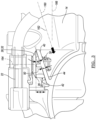
- FIGS. 1 - 3 illustrate a vehicle component 10 according to an embodiment.
- the vehicle component 10 shown is an intake manifold 12 for an internal combustion engine or a portion thereof.
- the vehicle component 10 may be a battery tray, an engine cam cover, or the like.
- the intake manifold 12 has a first shell portion 14 and a second shell portion 16 that cooperate to form the intake manifold.
- Each shell portion 14 , 16 may be molded from a polymer material, a plastic material, or a composite material, including a fiber or particle reinforced resin, as described in further detail below.
- the disclosure is not limited to the composite materials and forming processes included herein, and additional materials and processes may be used according to the spirit and scope of the disclosure.
- each shell portion 14 , 16 is formed using an injection molding process in a tool assembly or mold.
- the shell portion(s) 14 , 16 may be formed in a blow molding, compression molding, or other process that involves a tool assembly with multiple tool, slide, and/or die components.
- the vehicle component 10 provides one or more mounting features 20 for an accessory 22 .
- the mounting feature 20 is an aperture 24 and planar bearing surface 26 for a clip fastener 28 .
- the clip fastener 28 has a post section 30 or post, and a head section 32 , or head.
- the post section 30 may be inserted into the aperture 24 such that it extends into the aperture 24 , and may additionally be provided with retention features to retain the fastener 28 to the mounting feature 20 .
- the post section 30 may be inserted into the aperture 24 until the head section 32 is in contact with or abuts the planar bearing surface 26 .
- the bearing surface 26 therefore provide a support surface for the head section 32 of the fastener 28 , and the mounting feature 20 locates and orients the fastener 28 and accessory 22 relative to the vehicle component 10 .
- the head section 32 of the fastener 28 may be provided with one or more clamp devices, cable ties, or other features that allow for connection of the accessory 22 to the fastener.
- the accessory 22 is a wiring harness.
- fasteners 28 and mounting features 20 may be provided in various embodiments and according to the present disclosure and may be at least in part based on the vehicle accessory 22 to be mounted.
- the planar bearing surface 26 of the mounting feature 20 is required to be provided at a predetermined location relative to the component 10 , and at a predetermined orientation or angle on the component, in order to locate the fastener 28 and associated accessory 22 relative to the component 10 .
- the accessory 22 is a wiring harness
- the planar bearing surface 26 is provided to locate the harness 22 such that the harness has clearance relative to the component 10 , for example, as the cable or wires runs alongside the component.
- the mounting feature 20 and the clip fastener 28 cooperate to position the wire harness 22 such that it extends at a desired angle above the planar bearing surface and longitudinally along the shell 14 .
- the mounting feature 20 may be provided as a mounting box or other flange or similar extension from the shell 14 of the component 10 to provide the planar bearing surface 26 at the desired location and angle.
- the vehicle component 10 has a body 14 that is formed by a shell structure.
- the body 14 has a mounting feature 20 that is integrally formed with the body.
- the mounting feature 20 includes a member 40 such as a plate that extends outwardly from the shell 14 .
- the member plate 40 has a first surface 42 , or upper surface.
- the member also has a second surface 44 , or lower surface.
- the upper and lower surfaces 42 , 44 may be opposite to one another and spaced apart from one another.
- the upper and lower surfaces 42 , 44 may additionally be substantially parallel to one another and follow one another as shown.
- “substantially” with respect to an angular relationship refers to a variability of five degrees or less, and may provide for tooling draft clearance, and the like.
- An aperture 24 extends through the member 40 and intersects the upper and lower surfaces 42 , 44 .
- the upper and lower surfaces 42 , 44 may each surround the aperture 24 .
- the aperture 24 may be provided with various shapes based on the fastener 28 planned for use with the mounting feature 20 .
- An integrated rib 50 extends outwardly from the upper surface 42 to a planar bearing surface 26 , with the planar bearing surface 26 and integrated rib 50 surrounding the aperture 24 .
- the planar bearing surface 26 may be oriented at a nonperpendicular and nonparallel angle relative to the upper and lower surfaces 42 , 44 .
- the planar bearing surface 26 may be further oriented at an acute angle A relative to the upper and lower surfaces 42 , 44 .
- the integrated rib 50 may be provided by a tubular structure.
- the tubular rib structure may be further provided with a series of longitudinal secondary ribs 52 extending outwardly therefrom.
- Each secondary rib 52 may extend from the upper surface 42 to the planar bearing surface 26 , and may provide additional structural support for the integrated rib 50 and planar bearing surface 26 , as well as increasing the overall surface area of the planar bearing surface 26 .
- the series of ribs 52 may include any number of ribs, including one or more, and the number of ribs 52 may be increased to increase the overall bearing surface area or as needed for stiffness or structural support.
- the component 10 may be formed by a tool assembly as described below, and the tools, dies, and slides may be provided and configured for movement based on the major features of the shell 14 itself.
- the existing tooling for forming the shell 14 may be incapable of additionally forming the mounting feature, e.g. based on interferences caused between the mounting feature surfaces and the slide paths.
- an additional slide would be required to form the mounting feature, which adds complexity to the tooling as well as cost.
- FIG. 4 illustrates a process or method 100 of forming a vehicle component according to the present disclosure.
- FIG. 5 illustrates a tool assembly or a mold 150 for use with the method 100 .
- the mold 150 is described with respect to forming a shell 14 of an intake manifold 12 with an accessory mounting feature 20 , although the process and a tool to provide similar features may be applied to other vehicle components as described above.
- the method may include greater or fewer steps than shown, the steps may be rearranged in another order, and various steps may be performed serially or simultaneously according to various examples of the disclosure.
- the mold 150 has a first tool 152 and a second tool 154 .
- the mold 150 may have additional dies, slides or other components to form other regions of the vehicle component 10 .
- the tools and dies 152 , 154 may be formed from tool steel or another suitable material for repetitive use.
- the tools may be provided as die slides such that they assemble and mate with one another to form the tool assembly or mold with surface(s) for forming the vehicle component.
- Each die may be a cover die or an ejector die that cooperates with the other dies to form a mold cavity to form the vehicle component.
- the tool assembly or mold is provided for an injection molding process, for example, of a composite material, a polymer material, a thermoset material, a thermoplastic material, and the like.
- a first tool 152 is formed with a first surface 156 , such as a molding surface.
- a second tool 154 is formed with a second surface 158 , such as a molding surface.
- the first and second surfaces 156 , 158 cooperate with one another to form a mold cavity when the tool assembly 150 is in a closed configuration.
- the mold cavity is configured to form an accessory mount feature 20 with an aperture 24 .
- the first and second tool surfaces 156 , 158 may additionally be configured to form other portions of the vehicle component, e.g. portions of the shell 14 of the intake manifold 12 .
- the first surface 156 is configured to form a lower surface 44 of the mount feature 20 surrounding the aperture 24 .
- the second surface 158 is configured to form an integrated rib 50 extending outwardly from an upper surface 42 of the mount feature 20 to a planar bearing surface 26 surrounding the aperture 24 with the planar bearing surface 26 oriented at an acute angle A relative to the upper surface 42 .
- the lower surface 44 is substantially parallel to and spaced apart from the upper surface 42 .
- the second surface 158 may be further configured to form the integrated rib 50 as a tubular structure extending outwardly from the upper surface 42 of the mount feature to the planar bearing surface 26 .
- the second surface 158 may be further configured to provide the tubular rib structure 50 with a series of longitudinal secondary ribs 52 extending outwardly therefrom.
- Each secondary rib 52 may extend from the upper surface 42 to the planar bearing surface 26 , and may provide additional structural support for the integrated rib 50 and planar bearing surface 26 , as well as increasing the overall surface area of the planar bearing surface 26 .
- the series of secondary ribs 52 may include any number of ribs, including one or more, and the number of ribs may be increased to increase the overall bearing surface area.
- the first and second tools 152 , 154 are provided in a tool assembly 150 , and the tool assembly is operated and controlled to form a component.
- the first tool 152 is translated along a first axis 160 towards the second tool 154 .
- the first axis is substantially parallel to the upper surface 42 and the lower surface 44 .
- the first axis 160 is oriented at an acute angle A relative to the resulting planar bearing surface 26 .
- the first axis may be defined for the tool based on other surfaces of the component or shell, for example, adjacent port or passage 80 .
- a height H of the integrated rib 50 of the resulting mounting feature as measured between the planar bearing surface 26 and the upper surface 42 continually increases in the first direction.
- a distance between the planar bearing surface 26 and the lower surface 44 increases in the first direction 162 .
- the mold cavity formed by the first and second surfaces 156 , 158 of the first and second tools 152 , 154 defines the entirety of the accessory mounting feature 20 such that the mounting feature is formed without the use of a third tool despite the geometry. Therefore, as can be seen from the Figures, a conventional tool assembly would be otherwise provided with a third tool along a third axis 166 in order to form a mounting box for the desired bearing surface 26 , and to maintain a maximum wall thickness T of the component.
- the maximum wall thickness T is in the range of 3-4 millimeters, and having thicker regions than this may lead to molding and resulting component issues, for example, porosity issues.
- maximum wall thicknesses may be provided based on the injected material, tool assembly, and other considerations.
- the method 100 and tool 150 according to the present disclosure allows for the use of existing tooling to provide a mounting feature with the desired positioning for the bearing surface 26 while maintaining a predetermined maximum wall thickness T for the component.
- the second tool 154 is translated along a second axis 166 towards the first tool 152 , such that the first and second tools 152 , 154 converge to close the tool assembly 150 and form the mold cavity in preparation for an injection process.
- the second axis 164 is nonparallel and nonperpendicular to the first axis 160 .
- the second axis 164 is perpendicular to the planar bearing surface 26 according to one example.
- the first and second tools 152 , 154 may be moved simultaneously, or one after the other. In further examples, only one of the first and second tools 152 , 154 is moved, and the other remains fixed to a bed of the tool assembly 150 .
- the material includes a polymer material, a plastic material, or the like.
- the material is a composite material.
- the injection process may occur at a high pressure, and the tool assembly 150 may be heated and/or cooled as a part of the process to set the injected material.
- the material is injected and flows into the mold cavity of the tool assembly and into contact with the surfaces tools and dies.
- the tool assembly 150 After injecting material, the tool assembly 150 remains closed for a predetermined time to allow the formed component 10 to cool within the mold.
- the tool assembly 150 is then opened, for example, by translating the first tool 152 and second tool 154 away from one another by translating the first tool 152 along the first axis 160 and translating the second tool 152 along the second axis 164 .
- the component 10 may then be ejected or removed from the tool assembly 150 .
- the tool assembly or mold 150 therefore provides a vehicle component 10 , such as the intake manifold 12 of FIG. 1 , with a shell 14 and an accessory mounting feature 20 with a plana bearing surface 26 at a predetermined angle without changing the side areas or adding another slide or tool.
Abstract
Description
Claims (20)
Priority Applications (1)
| Application Number | Priority Date | Filing Date | Title |
|---|---|---|---|
| US17/019,776 US11637410B2 (en) | 2018-02-02 | 2020-09-14 | Vehicle component with an accessory mounting feature and a method and tool for forming |
Applications Claiming Priority (2)
| Application Number | Priority Date | Filing Date | Title |
|---|---|---|---|
| US15/887,202 US10808657B2 (en) | 2018-02-02 | 2018-02-02 | Vehicle component with an accessory mounting feature and a method and tool for forming |
| US17/019,776 US11637410B2 (en) | 2018-02-02 | 2020-09-14 | Vehicle component with an accessory mounting feature and a method and tool for forming |
Related Parent Applications (2)
| Application Number | Title | Priority Date | Filing Date |
|---|---|---|---|
| US15/877,202 Division US10348058B1 (en) | 2018-01-22 | 2018-01-22 | Two-dimensional material plasmonic laser |
| US15/887,202 Division US10808657B2 (en) | 2018-02-02 | 2018-02-02 | Vehicle component with an accessory mounting feature and a method and tool for forming |
Publications (2)
| Publication Number | Publication Date |
|---|---|
| US20200412096A1 US20200412096A1 (en) | 2020-12-31 |
| US11637410B2 true US11637410B2 (en) | 2023-04-25 |
Family
ID=67476560
Family Applications (2)
| Application Number | Title | Priority Date | Filing Date |
|---|---|---|---|
| US15/887,202 Active US10808657B2 (en) | 2018-02-02 | 2018-02-02 | Vehicle component with an accessory mounting feature and a method and tool for forming |
| US17/019,776 Active 2038-06-08 US11637410B2 (en) | 2018-02-02 | 2020-09-14 | Vehicle component with an accessory mounting feature and a method and tool for forming |
Family Applications Before (1)
| Application Number | Title | Priority Date | Filing Date |
|---|---|---|---|
| US15/887,202 Active US10808657B2 (en) | 2018-02-02 | 2018-02-02 | Vehicle component with an accessory mounting feature and a method and tool for forming |
Country Status (2)
| Country | Link |
|---|---|
| US (2) | US10808657B2 (en) |
| CN (1) | CN210121938U (en) |
Families Citing this family (1)
| Publication number | Priority date | Publication date | Assignee | Title |
|---|---|---|---|---|
| US11821393B1 (en) * | 2022-10-14 | 2023-11-21 | Ford Global Technologies, Llc | Integrated intake manifold |
Citations (142)
| Publication number | Priority date | Publication date | Assignee | Title |
|---|---|---|---|---|
| US3068520A (en) | 1960-01-29 | 1962-12-18 | Arburg Feingeraetefabrik Ohg | Injection molding machine |
| US3136001A (en) | 1963-05-31 | 1964-06-09 | Gen Electric | Mold for molding dynamically balanced fans |
| US3330019A (en) | 1963-09-16 | 1967-07-11 | Western Electric Co | Apparatus for molding terminals in workpieces |
| US3751109A (en) | 1970-10-02 | 1973-08-07 | Al Furniture Ltd Du | Method of making a seat shell |
| US3773454A (en) | 1971-09-20 | 1973-11-20 | Chicago Rawhide Mfg Co | Apparatus for precision injection molding of composite parts |
| US4005961A (en) | 1974-08-26 | 1977-02-01 | Creusot-Loire | Pivotally mounted injection molding apparatus |
| US4502660A (en) | 1983-11-21 | 1985-03-05 | Luther Leroy D | Mold including side walls with locking projections |
| US4630160A (en) | 1981-09-19 | 1986-12-16 | Honda Giken Kogyo Kabushiki Kaisha | Device for installing electronic equipment on a vehicle |
| US4692108A (en) | 1985-07-31 | 1987-09-08 | G.O.R. Applicazioni Speciali S.P.A. | Mold for the covering and trimming of products of plastics material |
| US5028230A (en) | 1989-03-23 | 1991-07-02 | Fisher & Paykel Limited | Machine for handling molds in injection molding |
| US5209191A (en) | 1990-12-03 | 1993-05-11 | Filterwerk Mann & Hummel Gmbh | Air intake manifold for an internal combustion engine |
| US5238387A (en) | 1988-12-09 | 1993-08-24 | Honda Giken Kogyo Kabushiki Kaisha | Apparatus for molding a product of synthetic resin |
| US5243933A (en) | 1992-02-05 | 1993-09-14 | Fuji Jukogyo Kabushiki Kaisha | Plastic intake pipe and the method thereof |
| US5324151A (en) | 1993-03-29 | 1994-06-28 | United Technologies Automotive, Inc. | Anti-rotational fastener |
| US5339491A (en) | 1992-11-06 | 1994-08-23 | United Technologies Automotive, Inc. | Sealed retainer grommet |
| US5356590A (en) | 1992-08-04 | 1994-10-18 | Tooling Technology Centre Inc. | Method of moulding an attachment structure to a moulded part |
| US5616891A (en) | 1993-12-08 | 1997-04-01 | Plasto Sa | Sealing panel, in particular for automobiles, including a loudspeaker housing |
| US5642697A (en) | 1995-06-07 | 1997-07-01 | Volkswagen Ag | Intake manifold for an internal combustion engine |
| US5806139A (en) | 1996-04-24 | 1998-09-15 | Hi-Lex Corporation | Grommet assembly |
| US5839404A (en) * | 1996-04-16 | 1998-11-24 | Honda Giken Kogyo Kabushiki Kaisha | Intake system in engine |
| US5908643A (en) | 1996-06-12 | 1999-06-01 | Sturm, Ruger & Company, Inc. | Injection mold apparatus for producing a pattern |
| US5924634A (en) | 1995-03-29 | 1999-07-20 | Robert Bosch Gmbh | Orifice plate, in particular for injection valves, and method for manufacturing an orifice plate |
| US5928453A (en) | 1996-05-14 | 1999-07-27 | Mitsubishi Jidosha Kogyo Kabushiki Kaisha | Joining process of resin members |
| US5935504A (en) | 1998-01-26 | 1999-08-10 | Gemtron Corporation | Method for substituting horizontally and vertically opening molds |
| US6019929A (en) | 1997-12-17 | 2000-02-01 | Noggle; Michael K. | Mold shuttle system, apparatus, and method |
| US6120274A (en) | 1997-11-26 | 2000-09-19 | Donnelly Corporation | Mold assembly for molding a remotely located attachment member on a sheet of material |
| US6123535A (en) | 1996-08-02 | 2000-09-26 | Libbey-Owens-Ford Co. | Molding apparatus for encapsulating a part |
| US6257897B1 (en) | 1999-04-13 | 2001-07-10 | Yazaki Corporation | Wiring harness device for instrument panels |
| US6276109B1 (en) * | 1999-12-20 | 2001-08-21 | General Motors Corporation | Motor vehicle trim panel assembly and method |
| US20010040313A1 (en) | 2000-05-12 | 2001-11-15 | Franco Cesano | Process and equipment for hot moulding of articles made of thermoplastic material |
| US6363900B1 (en) | 1998-09-01 | 2002-04-02 | G P Daikyo Corporation | Synthetic resin-made intake manifold and manufacturing method thereof |
| US6368448B1 (en) | 1998-01-09 | 2002-04-09 | G P Daikyo Corporation | Method for joining thermoplastic resin molded products |
| US20020084122A1 (en) | 2000-12-07 | 2002-07-04 | Norio Emori | Radiator core support structure for vehicle |
| US20020088423A1 (en) | 1999-03-15 | 2002-07-11 | Hitachi, Ltd. | Air intake apparatus for an internal combustion engine |
| US6418888B1 (en) | 2000-10-24 | 2002-07-16 | Siemens Vdo Automotive, Inc. | Ultra sonic or heat staked fastening for air intake manifold active system |
| US20020151210A1 (en) | 1999-04-22 | 2002-10-17 | Harvinder Singh | Continuous conductor connector system for printed circuit boards |
| US20020174532A1 (en) | 2001-05-18 | 2002-11-28 | Skov Erik L. | Apparatus and method for mounting accessory devices to panels |
| US6502547B2 (en) | 2000-01-28 | 2003-01-07 | Siemens Vdo Automotive Inc. | Foamed over integrated circuit for intake manifold |
| US6533568B1 (en) | 1999-07-27 | 2003-03-18 | Filterwerk Mann & Hummel Gmbh | Casting mold with an extractable core for producing a shell of an air intake duct |
| US20030169522A1 (en) | 2002-01-31 | 2003-09-11 | Kenneth Schofield | Vehicle accessory module |
| US6772484B2 (en) | 2000-09-28 | 2004-08-10 | Toyoda Gosei Co., Ltd | Mounting structure for mounting a resin molded article to a body panel |
| US20040154574A1 (en) | 2002-11-20 | 2004-08-12 | Mark Iv Systemes Moteurs (Sa) | Intake manifold in two parts |
| US20040178660A1 (en) | 2003-02-19 | 2004-09-16 | Dry Alan G. | Method of forming a vehicle component |
| US20040194750A1 (en) | 2003-04-07 | 2004-10-07 | Hironori Tanikawa | Resin intake manifold |
| US20040200450A1 (en) | 2003-04-09 | 2004-10-14 | Hironori Tanikawa | Resin intake manifold |
| US20050005890A1 (en) | 2003-07-10 | 2005-01-13 | Dow Global Technologies Inc. | Engine intake manifold assembly |
| US20050022771A1 (en) * | 2003-07-31 | 2005-02-03 | Cicone Nick A. | Manifold sensor retention system |
| US6932416B2 (en) | 2003-01-09 | 2005-08-23 | Lear Corporation | Vehicular door trim having a molded-in substrate fastener |
| US20050227042A1 (en) | 2004-04-08 | 2005-10-13 | Lear Corporation | Two-shot polymeric component with attachment feature and method of producing same |
| US20050227043A1 (en) | 2004-04-08 | 2005-10-13 | Lear Corporation | Two-shot polymeric component with wrapped edge and a method of producing same |
| US20050274452A1 (en) | 2004-06-11 | 2005-12-15 | Schoemann Michael P | Method of forming a vehicle component |
| US20050279892A1 (en) | 2004-06-17 | 2005-12-22 | Zdravko Kovac | Radiator hose bracket |
| US20060072917A1 (en) | 2004-10-06 | 2006-04-06 | Honda Motor Co., Ltd. | Structure for attaching stereoscopic camera in vehicle |
| US20060117535A1 (en) * | 2003-05-09 | 2006-06-08 | Lear Corporation | High strength fastening system |
| US7096849B1 (en) | 2005-07-12 | 2006-08-29 | Steeda Autosports, Inc. | Charge motion control plate kit |
| US7165371B2 (en) * | 2000-10-13 | 2007-01-23 | Altia Hashimoto Co., Ltd. | Automobile molding and fastener therefor |
| US20070107174A1 (en) * | 2005-11-17 | 2007-05-17 | Faurecia Interior Systems U.S.A., Inc. | Methods and apparatus for fastening panels |
| US20070141193A1 (en) | 2005-12-19 | 2007-06-21 | Kanagawaseiki Co., Ltd. | Mold apparatus for injection molding |
| US20070210616A1 (en) | 2002-12-10 | 2007-09-13 | Wenzel Edward J | Integrated structural member for a vehicle and method of making |
| US20080054522A1 (en) | 2006-06-26 | 2008-03-06 | Summerer Franz J | Injection moulding machine and injection moulding method for injection moulding plastics mouldings having a plurality of de-moulding directions |
| US20080079191A1 (en) | 2006-09-28 | 2008-04-03 | The Japan Steel Works, Ltd. | Method and apparatus for forming hollow moldings having thin film on inner surface |
| US20080211137A1 (en) | 2005-06-28 | 2008-09-04 | Faurecia Innenraum Systeme Gbmh | Method and Tool for Producing a Plastic Component with a Decorative Layer, a Backing Layer and an Additional Molded Part Attached Thereto |
| US7534134B2 (en) | 2006-03-11 | 2009-05-19 | Hon Hai Precision Ind. Co., Ltd. | Electrical connector retaining mechanism having slide clip member |
| US20090145042A1 (en) | 2005-09-09 | 2009-06-11 | Hans-Helmut Mieglitz | Inner cladding of a motor vehicle door comprising a cable harness |
| US7556007B2 (en) | 2006-12-11 | 2009-07-07 | Delphi Technologies, Inc. | Method and apparatus for forming a septum for an engine intake manifold |
| US20100003464A1 (en) | 2006-08-09 | 2010-01-07 | Toyota Shatai Kabushiki Kaisha | Interior Panel and Injection Molding Method |
| US20100031912A1 (en) | 2008-08-11 | 2010-02-11 | Rolland Francis V | Engine air intake manifold having a shell |
| US20100040720A1 (en) | 2005-12-28 | 2010-02-18 | Yuusuke Nakagawa | Metal mold for molded article |
| US20100078842A1 (en) | 2008-09-29 | 2010-04-01 | Ti Group Automotive Systems, L.L.C. | Fuel tank opening |
| US20100155981A1 (en) | 2006-01-17 | 2010-06-24 | Yoshihisa Miyabe | Molding die and method for molding a molded article |
| US20100229821A1 (en) | 2009-03-13 | 2010-09-16 | Filtrauto | Plastic Structural Oil Sump with Fitted-on Bottom for a Combustion Engine and Method of Fabricating such a Sump |
| US20100244317A1 (en) | 2007-12-18 | 2010-09-30 | Tetra Laval Holdings & Finance S.A. | Apparatus for moulding a part of a packaging container |
| US20100288247A1 (en) | 2009-05-18 | 2010-11-18 | Aisan Kogyo Kabushiki Kaisha | Intake manifolds |
| US7837248B2 (en) | 2008-04-15 | 2010-11-23 | Ford Global Technologies, Llc | Trim system for an automotive vehicle |
| US20110035909A1 (en) * | 2009-08-11 | 2011-02-17 | Toyota Motor Engineering & Manufacturing North America, Inc. | Trim panel having a clip retention feature |
| US20110115117A1 (en) | 2008-03-26 | 2011-05-19 | Delta Engineered Plastics | Interchangeable mold tooling |
| US20110169186A1 (en) | 2010-01-11 | 2011-07-14 | Brenda Bruman | Method for Producing Three Separate and Distinct Intake Manifolds from a Single Intake Manifold Casting For Three Different Multi-Cylinder Internal Combustion Engine Applications |
| US20110221091A1 (en) | 2008-11-19 | 2011-09-15 | Johnson Controls Automotive S.R.L. | Method and mould for thermoforming and folding a plastic sheet |
| US8113475B2 (en) | 2006-05-02 | 2012-02-14 | Zipwall, Llc | Accessory mounting systems |
| US20120110796A1 (en) | 2008-11-04 | 2012-05-10 | Jean Luc Klein | Fastening clip |
| US20120200097A1 (en) | 2009-10-21 | 2012-08-09 | Toyota Jidosha Kabushiki Kaisha | Mold structure and bumper |
| US20120204982A1 (en) | 2011-02-15 | 2012-08-16 | Nidec Motor Corporation | Weld-line elimination on molded plastic parts |
| US20120238150A1 (en) | 2011-03-15 | 2012-09-20 | Sumitomo Wiring Systems, Ltd. | Device connector and method of manufacture |
| US8272675B2 (en) | 2010-03-10 | 2012-09-25 | Ford Global Technologies, Llc | Equipment mounting module for instrument panel |
| US20120257924A1 (en) * | 2011-04-06 | 2012-10-11 | Jeffrey Andrews | Molded attachment clip |
| US20120301568A1 (en) | 2011-05-26 | 2012-11-29 | Ti Automotive Technology Center Gmbh | Receptacle with mount feature |
| US20120319427A1 (en) | 2011-06-17 | 2012-12-20 | Honda Motor Co., Ltd. | Integrated sunshade design |
| US20130039694A1 (en) | 2010-04-28 | 2013-02-14 | Audi Ag | Component for a motor vehicle |
| US20130078403A1 (en) | 2010-03-30 | 2013-03-28 | Nec Personal Computers, Ltd | Injection molding device, injection molding method and housing |
| US8474845B2 (en) | 2009-12-02 | 2013-07-02 | Ford Global Technologies, Llc | Wheel suspension |
| US20130273191A1 (en) | 2012-04-13 | 2013-10-17 | International Automotive Components Group of North America, Inc. | Molds and methods for in-mold trimming of a molded product |
| US20130277886A1 (en) | 2012-04-23 | 2013-10-24 | Honda Motor Co., Ltd. | Mold for vehicle bumper fascia and associated molding technique |
| US20130320742A1 (en) | 2012-05-29 | 2013-12-05 | Faurecia Automotive Seating, Llc | Vehicle seat assembly with composite frame |
| US8628139B2 (en) | 2010-07-14 | 2014-01-14 | Ford Global Technologies, Llc | Safety structure for vehicles |
| US8671528B2 (en) * | 2009-06-12 | 2014-03-18 | Piolax, Inc. | Assembling construction of clip to mountable member |
| US20140216386A1 (en) | 2011-11-10 | 2014-08-07 | Aisin Seiki Kabushiki Kaisha | Resin molding mold for intake manifold, intake manifold and method of resin molding for intake manifold |
| US20140241830A1 (en) | 2013-02-25 | 2014-08-28 | Mann+Hummel Gmbh | Device for Connecting Two Components, Holding Means of Such a Device, and Component |
| US20140311143A1 (en) | 2013-04-23 | 2014-10-23 | Mann+Hummel Gmbh | Air-Guiding Component with an Intercooler |
| US8877113B2 (en) * | 2012-05-21 | 2014-11-04 | Toyota Boshoku Kabushiki Kaisha | Method of molding clip mount and trim board |
| US20140367888A1 (en) | 2012-02-13 | 2014-12-18 | Nec Infrontia Corporation | Resin molding die, resin molding method and resin molded product |
| US20140374564A1 (en) | 2013-02-11 | 2014-12-25 | Ferno-Washington, Inc. | Equipment mounting system |
| US20140374957A1 (en) * | 2013-06-24 | 2014-12-25 | Quanta Computer Inc. | Mold and method for forming tilt boss |
| US8939745B2 (en) | 2011-08-30 | 2015-01-27 | Johnson Controls Technology Company | System and method for manufacturing a vehicle trim component via concurrent compression forming and injection molding |
| US20150078817A1 (en) | 2013-08-27 | 2015-03-19 | Honda Motor Co., Ltd. | Coupling structure for resin parts, and method of manufacturing same |
| US20150114335A1 (en) | 2012-06-21 | 2015-04-30 | Nissan Motor Co., Ltd. | Intake manifold for internal combustion engine |
| US20150125200A1 (en) | 2013-11-05 | 2015-05-07 | Delphi Technologies, Inc. | Housing with self-mounting feature |
| US20150211274A1 (en) * | 2014-01-29 | 2015-07-30 | Toyota Motor Engineering & Manufacturing North America, Inc. | Cover assembly for attaching to a hinge arm |
| US20150266429A1 (en) | 2014-03-19 | 2015-09-24 | GM Global Technology Operations LLC | Assembly with slip joint for fastening vehicle component and method of assembly |
| US20150283955A1 (en) | 2012-12-10 | 2015-10-08 | Toyota Jidosha Kabushiki Kaisha | Vehicle mounting structure for electronic device |
| US20150291012A1 (en) | 2014-04-10 | 2015-10-15 | Toyota Motor Engineering & Manufacturing North America, Inc. | Two piece housing assembly with elongated attachment and method for making the same |
| US20150367550A1 (en) | 2013-12-16 | 2015-12-24 | Lockheed Martin Corporation | Open-Face Molding |
| US20160061167A1 (en) * | 2013-05-29 | 2016-03-03 | Aisin Seiki Kabushiki Kaisha | Air intake apparatus |
| US20160082630A1 (en) | 2014-09-18 | 2016-03-24 | Ford Global Technologies, Llc | Plastic part with reduced read-through |
| US9326053B2 (en) | 2014-03-10 | 2016-04-26 | Ford Global Technologies, Llc | Flat panel speaker assembly integrated with vehicle trim |
| US20160115918A1 (en) | 2014-10-28 | 2016-04-28 | Ford Global Technologies, Llc | Integrally-molded intake manifold connector for engine cover of combustion engine |
| US20160169171A1 (en) | 2014-12-15 | 2016-06-16 | Ford Global Technologies, Llc. | Modular intake manifold |
| US9463831B2 (en) * | 2013-09-09 | 2016-10-11 | GM Global Technology Operations LLC | Elastic tube alignment and fastening system for providing precise alignment and fastening of components |
| US20170001350A1 (en) | 2015-07-02 | 2017-01-05 | Hyundai Motor Company | Thin type injection molding skin manufacturing apparatus and skin taking out method of the same |
| US9551307B1 (en) | 2015-07-21 | 2017-01-24 | Ford Global Technologies, Llc | Hinged engine cover for intake manifold |
| US20170066166A1 (en) | 2015-09-04 | 2017-03-09 | Kia Motors Corporation | Apparatus and method for manufacturing vehicular interior part |
| US20170113625A1 (en) | 2015-10-24 | 2017-04-27 | Audi Ag | Fastening arrangement for securing a unit mount and a stabilizer mount |
| US9669770B1 (en) * | 2016-04-15 | 2017-06-06 | GM Global Technology Operations LLC | Adjustable fastener-holder assembly |
| US20170182729A1 (en) | 2011-08-30 | 2017-06-29 | Shanghai Yanfeng Jinqiao Automotive Trim Systems Co., Ltd. | Trim component for vehicle interior |
| US20170248162A1 (en) | 2014-10-23 | 2017-08-31 | Elringklinger Ag | Method for producing a plastic component and plastic component |
| US20170291556A1 (en) | 2014-11-14 | 2017-10-12 | Panasonic Intellectual Property Management Co., Ltd. | Vehicle-mounted-camera bracket |
| US20170302062A1 (en) | 2016-01-04 | 2017-10-19 | Nexans | Threaded hole retainer |
| US20170348918A1 (en) | 2015-07-10 | 2017-12-07 | Cooper Standard GmbH | Method for manufacturing a composite part and composite part |
| US9919743B2 (en) | 2015-03-19 | 2018-03-20 | Ford Global Technologies, Llc | Front end of a motor vehicle |
| US20180087553A1 (en) * | 2016-09-29 | 2018-03-29 | Magna Exteriors Inc. | Fastener locating and retention design to accommodate part expansion and contraction |
| US20180093399A1 (en) | 2016-10-04 | 2018-04-05 | Dr. Ing. H.C. F. Porsche Aktiengesellschaft | Method for producing a vehicle substructure, and vehicle substructure |
| US20180094662A1 (en) * | 2014-03-27 | 2018-04-05 | Gregory Compton | Bidirectional modular assembly clip |
| US20180142609A1 (en) | 2016-11-23 | 2018-05-24 | Hyundai Kefico Corporation | Intake apparatus for engine |
| US20180215081A1 (en) | 2015-07-30 | 2018-08-02 | Nissan Motor Co., Ltd. | Die assembly for intake port insert |
| US20180229411A1 (en) | 2017-02-15 | 2018-08-16 | Daniel Aquilina | Injection mold for ultra thin wall components |
| US10065571B1 (en) | 2017-04-12 | 2018-09-04 | Ford Global Technologies, Llc | Structural subwoofer |
| US20180266372A1 (en) * | 2017-03-15 | 2018-09-20 | Brp-Rotax Gmbh & Co. Kg | Method and system for manufacturing a family of intake manifolds for a family of internal combustion engines |
| US10093268B2 (en) | 2012-08-27 | 2018-10-09 | Shanghai Yanfeng Jinqiao Automotive Trim Systems Co. Ltd. | Trim component for vehicle interior |
| US20180345548A1 (en) | 2017-06-05 | 2018-12-06 | GM Global Technology Operations LLC | Molding system and method for multiple components |
| US20180370457A1 (en) | 2015-12-28 | 2018-12-27 | Lydall, Inc. | Heat shield with retention feature |
| US10208720B2 (en) | 2015-12-15 | 2019-02-19 | Mahle Filter Systems Japan Corporation | Intake manifold |
| US20190061651A1 (en) | 2017-08-31 | 2019-02-28 | Yazaki Corporation | Protector |
| US10876559B2 (en) * | 2016-02-02 | 2020-12-29 | Bayerische Motoren Werke Aktiengesellschaft | Panel assembly for a motor vehicle |
-
2018
- 2018-02-02 US US15/887,202 patent/US10808657B2/en active Active
-
2019
- 2019-02-02 CN CN201920186140.0U patent/CN210121938U/en active Active
-
2020
- 2020-09-14 US US17/019,776 patent/US11637410B2/en active Active
Patent Citations (142)
| Publication number | Priority date | Publication date | Assignee | Title |
|---|---|---|---|---|
| US3068520A (en) | 1960-01-29 | 1962-12-18 | Arburg Feingeraetefabrik Ohg | Injection molding machine |
| US3136001A (en) | 1963-05-31 | 1964-06-09 | Gen Electric | Mold for molding dynamically balanced fans |
| US3330019A (en) | 1963-09-16 | 1967-07-11 | Western Electric Co | Apparatus for molding terminals in workpieces |
| US3751109A (en) | 1970-10-02 | 1973-08-07 | Al Furniture Ltd Du | Method of making a seat shell |
| US3773454A (en) | 1971-09-20 | 1973-11-20 | Chicago Rawhide Mfg Co | Apparatus for precision injection molding of composite parts |
| US4005961A (en) | 1974-08-26 | 1977-02-01 | Creusot-Loire | Pivotally mounted injection molding apparatus |
| US4630160A (en) | 1981-09-19 | 1986-12-16 | Honda Giken Kogyo Kabushiki Kaisha | Device for installing electronic equipment on a vehicle |
| US4502660A (en) | 1983-11-21 | 1985-03-05 | Luther Leroy D | Mold including side walls with locking projections |
| US4692108A (en) | 1985-07-31 | 1987-09-08 | G.O.R. Applicazioni Speciali S.P.A. | Mold for the covering and trimming of products of plastics material |
| US5238387A (en) | 1988-12-09 | 1993-08-24 | Honda Giken Kogyo Kabushiki Kaisha | Apparatus for molding a product of synthetic resin |
| US5028230A (en) | 1989-03-23 | 1991-07-02 | Fisher & Paykel Limited | Machine for handling molds in injection molding |
| US5209191A (en) | 1990-12-03 | 1993-05-11 | Filterwerk Mann & Hummel Gmbh | Air intake manifold for an internal combustion engine |
| US5243933A (en) | 1992-02-05 | 1993-09-14 | Fuji Jukogyo Kabushiki Kaisha | Plastic intake pipe and the method thereof |
| US5356590A (en) | 1992-08-04 | 1994-10-18 | Tooling Technology Centre Inc. | Method of moulding an attachment structure to a moulded part |
| US5339491A (en) | 1992-11-06 | 1994-08-23 | United Technologies Automotive, Inc. | Sealed retainer grommet |
| US5324151A (en) | 1993-03-29 | 1994-06-28 | United Technologies Automotive, Inc. | Anti-rotational fastener |
| US5616891A (en) | 1993-12-08 | 1997-04-01 | Plasto Sa | Sealing panel, in particular for automobiles, including a loudspeaker housing |
| US5924634A (en) | 1995-03-29 | 1999-07-20 | Robert Bosch Gmbh | Orifice plate, in particular for injection valves, and method for manufacturing an orifice plate |
| US5642697A (en) | 1995-06-07 | 1997-07-01 | Volkswagen Ag | Intake manifold for an internal combustion engine |
| US5839404A (en) * | 1996-04-16 | 1998-11-24 | Honda Giken Kogyo Kabushiki Kaisha | Intake system in engine |
| US5806139A (en) | 1996-04-24 | 1998-09-15 | Hi-Lex Corporation | Grommet assembly |
| US5928453A (en) | 1996-05-14 | 1999-07-27 | Mitsubishi Jidosha Kogyo Kabushiki Kaisha | Joining process of resin members |
| US5908643A (en) | 1996-06-12 | 1999-06-01 | Sturm, Ruger & Company, Inc. | Injection mold apparatus for producing a pattern |
| US6123535A (en) | 1996-08-02 | 2000-09-26 | Libbey-Owens-Ford Co. | Molding apparatus for encapsulating a part |
| US6120274A (en) | 1997-11-26 | 2000-09-19 | Donnelly Corporation | Mold assembly for molding a remotely located attachment member on a sheet of material |
| US6019929A (en) | 1997-12-17 | 2000-02-01 | Noggle; Michael K. | Mold shuttle system, apparatus, and method |
| US6368448B1 (en) | 1998-01-09 | 2002-04-09 | G P Daikyo Corporation | Method for joining thermoplastic resin molded products |
| US5935504A (en) | 1998-01-26 | 1999-08-10 | Gemtron Corporation | Method for substituting horizontally and vertically opening molds |
| US6363900B1 (en) | 1998-09-01 | 2002-04-02 | G P Daikyo Corporation | Synthetic resin-made intake manifold and manufacturing method thereof |
| US20020088423A1 (en) | 1999-03-15 | 2002-07-11 | Hitachi, Ltd. | Air intake apparatus for an internal combustion engine |
| US6257897B1 (en) | 1999-04-13 | 2001-07-10 | Yazaki Corporation | Wiring harness device for instrument panels |
| US20020151210A1 (en) | 1999-04-22 | 2002-10-17 | Harvinder Singh | Continuous conductor connector system for printed circuit boards |
| US6533568B1 (en) | 1999-07-27 | 2003-03-18 | Filterwerk Mann & Hummel Gmbh | Casting mold with an extractable core for producing a shell of an air intake duct |
| US6276109B1 (en) * | 1999-12-20 | 2001-08-21 | General Motors Corporation | Motor vehicle trim panel assembly and method |
| US6502547B2 (en) | 2000-01-28 | 2003-01-07 | Siemens Vdo Automotive Inc. | Foamed over integrated circuit for intake manifold |
| US20010040313A1 (en) | 2000-05-12 | 2001-11-15 | Franco Cesano | Process and equipment for hot moulding of articles made of thermoplastic material |
| US6772484B2 (en) | 2000-09-28 | 2004-08-10 | Toyoda Gosei Co., Ltd | Mounting structure for mounting a resin molded article to a body panel |
| US7165371B2 (en) * | 2000-10-13 | 2007-01-23 | Altia Hashimoto Co., Ltd. | Automobile molding and fastener therefor |
| US6418888B1 (en) | 2000-10-24 | 2002-07-16 | Siemens Vdo Automotive, Inc. | Ultra sonic or heat staked fastening for air intake manifold active system |
| US20020084122A1 (en) | 2000-12-07 | 2002-07-04 | Norio Emori | Radiator core support structure for vehicle |
| US20020174532A1 (en) | 2001-05-18 | 2002-11-28 | Skov Erik L. | Apparatus and method for mounting accessory devices to panels |
| US20030169522A1 (en) | 2002-01-31 | 2003-09-11 | Kenneth Schofield | Vehicle accessory module |
| US20040154574A1 (en) | 2002-11-20 | 2004-08-12 | Mark Iv Systemes Moteurs (Sa) | Intake manifold in two parts |
| US20070210616A1 (en) | 2002-12-10 | 2007-09-13 | Wenzel Edward J | Integrated structural member for a vehicle and method of making |
| US6932416B2 (en) | 2003-01-09 | 2005-08-23 | Lear Corporation | Vehicular door trim having a molded-in substrate fastener |
| US20040178660A1 (en) | 2003-02-19 | 2004-09-16 | Dry Alan G. | Method of forming a vehicle component |
| US20040194750A1 (en) | 2003-04-07 | 2004-10-07 | Hironori Tanikawa | Resin intake manifold |
| US20040200450A1 (en) | 2003-04-09 | 2004-10-14 | Hironori Tanikawa | Resin intake manifold |
| US20060117535A1 (en) * | 2003-05-09 | 2006-06-08 | Lear Corporation | High strength fastening system |
| US20050005890A1 (en) | 2003-07-10 | 2005-01-13 | Dow Global Technologies Inc. | Engine intake manifold assembly |
| US20050022771A1 (en) * | 2003-07-31 | 2005-02-03 | Cicone Nick A. | Manifold sensor retention system |
| US20050227042A1 (en) | 2004-04-08 | 2005-10-13 | Lear Corporation | Two-shot polymeric component with attachment feature and method of producing same |
| US20050227043A1 (en) | 2004-04-08 | 2005-10-13 | Lear Corporation | Two-shot polymeric component with wrapped edge and a method of producing same |
| US20050274452A1 (en) | 2004-06-11 | 2005-12-15 | Schoemann Michael P | Method of forming a vehicle component |
| US20050279892A1 (en) | 2004-06-17 | 2005-12-22 | Zdravko Kovac | Radiator hose bracket |
| US20060072917A1 (en) | 2004-10-06 | 2006-04-06 | Honda Motor Co., Ltd. | Structure for attaching stereoscopic camera in vehicle |
| US20080211137A1 (en) | 2005-06-28 | 2008-09-04 | Faurecia Innenraum Systeme Gbmh | Method and Tool for Producing a Plastic Component with a Decorative Layer, a Backing Layer and an Additional Molded Part Attached Thereto |
| US7096849B1 (en) | 2005-07-12 | 2006-08-29 | Steeda Autosports, Inc. | Charge motion control plate kit |
| US20090145042A1 (en) | 2005-09-09 | 2009-06-11 | Hans-Helmut Mieglitz | Inner cladding of a motor vehicle door comprising a cable harness |
| US20070107174A1 (en) * | 2005-11-17 | 2007-05-17 | Faurecia Interior Systems U.S.A., Inc. | Methods and apparatus for fastening panels |
| US20070141193A1 (en) | 2005-12-19 | 2007-06-21 | Kanagawaseiki Co., Ltd. | Mold apparatus for injection molding |
| US20100040720A1 (en) | 2005-12-28 | 2010-02-18 | Yuusuke Nakagawa | Metal mold for molded article |
| US20100155981A1 (en) | 2006-01-17 | 2010-06-24 | Yoshihisa Miyabe | Molding die and method for molding a molded article |
| US7534134B2 (en) | 2006-03-11 | 2009-05-19 | Hon Hai Precision Ind. Co., Ltd. | Electrical connector retaining mechanism having slide clip member |
| US8113475B2 (en) | 2006-05-02 | 2012-02-14 | Zipwall, Llc | Accessory mounting systems |
| US20080054522A1 (en) | 2006-06-26 | 2008-03-06 | Summerer Franz J | Injection moulding machine and injection moulding method for injection moulding plastics mouldings having a plurality of de-moulding directions |
| US20100003464A1 (en) | 2006-08-09 | 2010-01-07 | Toyota Shatai Kabushiki Kaisha | Interior Panel and Injection Molding Method |
| US20080079191A1 (en) | 2006-09-28 | 2008-04-03 | The Japan Steel Works, Ltd. | Method and apparatus for forming hollow moldings having thin film on inner surface |
| US7556007B2 (en) | 2006-12-11 | 2009-07-07 | Delphi Technologies, Inc. | Method and apparatus for forming a septum for an engine intake manifold |
| US20100244317A1 (en) | 2007-12-18 | 2010-09-30 | Tetra Laval Holdings & Finance S.A. | Apparatus for moulding a part of a packaging container |
| US20110115117A1 (en) | 2008-03-26 | 2011-05-19 | Delta Engineered Plastics | Interchangeable mold tooling |
| US7837248B2 (en) | 2008-04-15 | 2010-11-23 | Ford Global Technologies, Llc | Trim system for an automotive vehicle |
| US20100031912A1 (en) | 2008-08-11 | 2010-02-11 | Rolland Francis V | Engine air intake manifold having a shell |
| US20100078842A1 (en) | 2008-09-29 | 2010-04-01 | Ti Group Automotive Systems, L.L.C. | Fuel tank opening |
| US20120110796A1 (en) | 2008-11-04 | 2012-05-10 | Jean Luc Klein | Fastening clip |
| US20110221091A1 (en) | 2008-11-19 | 2011-09-15 | Johnson Controls Automotive S.R.L. | Method and mould for thermoforming and folding a plastic sheet |
| US20100229821A1 (en) | 2009-03-13 | 2010-09-16 | Filtrauto | Plastic Structural Oil Sump with Fitted-on Bottom for a Combustion Engine and Method of Fabricating such a Sump |
| US20100288247A1 (en) | 2009-05-18 | 2010-11-18 | Aisan Kogyo Kabushiki Kaisha | Intake manifolds |
| US8671528B2 (en) * | 2009-06-12 | 2014-03-18 | Piolax, Inc. | Assembling construction of clip to mountable member |
| US20110035909A1 (en) * | 2009-08-11 | 2011-02-17 | Toyota Motor Engineering & Manufacturing North America, Inc. | Trim panel having a clip retention feature |
| US20120200097A1 (en) | 2009-10-21 | 2012-08-09 | Toyota Jidosha Kabushiki Kaisha | Mold structure and bumper |
| US8474845B2 (en) | 2009-12-02 | 2013-07-02 | Ford Global Technologies, Llc | Wheel suspension |
| US20110169186A1 (en) | 2010-01-11 | 2011-07-14 | Brenda Bruman | Method for Producing Three Separate and Distinct Intake Manifolds from a Single Intake Manifold Casting For Three Different Multi-Cylinder Internal Combustion Engine Applications |
| US8272675B2 (en) | 2010-03-10 | 2012-09-25 | Ford Global Technologies, Llc | Equipment mounting module for instrument panel |
| US20130078403A1 (en) | 2010-03-30 | 2013-03-28 | Nec Personal Computers, Ltd | Injection molding device, injection molding method and housing |
| US20130039694A1 (en) | 2010-04-28 | 2013-02-14 | Audi Ag | Component for a motor vehicle |
| US8628139B2 (en) | 2010-07-14 | 2014-01-14 | Ford Global Technologies, Llc | Safety structure for vehicles |
| US20120204982A1 (en) | 2011-02-15 | 2012-08-16 | Nidec Motor Corporation | Weld-line elimination on molded plastic parts |
| US20120238150A1 (en) | 2011-03-15 | 2012-09-20 | Sumitomo Wiring Systems, Ltd. | Device connector and method of manufacture |
| US20120257924A1 (en) * | 2011-04-06 | 2012-10-11 | Jeffrey Andrews | Molded attachment clip |
| US20120301568A1 (en) | 2011-05-26 | 2012-11-29 | Ti Automotive Technology Center Gmbh | Receptacle with mount feature |
| US20120319427A1 (en) | 2011-06-17 | 2012-12-20 | Honda Motor Co., Ltd. | Integrated sunshade design |
| US20170182729A1 (en) | 2011-08-30 | 2017-06-29 | Shanghai Yanfeng Jinqiao Automotive Trim Systems Co., Ltd. | Trim component for vehicle interior |
| US8939745B2 (en) | 2011-08-30 | 2015-01-27 | Johnson Controls Technology Company | System and method for manufacturing a vehicle trim component via concurrent compression forming and injection molding |
| US20140216386A1 (en) | 2011-11-10 | 2014-08-07 | Aisin Seiki Kabushiki Kaisha | Resin molding mold for intake manifold, intake manifold and method of resin molding for intake manifold |
| US20140367888A1 (en) | 2012-02-13 | 2014-12-18 | Nec Infrontia Corporation | Resin molding die, resin molding method and resin molded product |
| US20130273191A1 (en) | 2012-04-13 | 2013-10-17 | International Automotive Components Group of North America, Inc. | Molds and methods for in-mold trimming of a molded product |
| US20130277886A1 (en) | 2012-04-23 | 2013-10-24 | Honda Motor Co., Ltd. | Mold for vehicle bumper fascia and associated molding technique |
| US8877113B2 (en) * | 2012-05-21 | 2014-11-04 | Toyota Boshoku Kabushiki Kaisha | Method of molding clip mount and trim board |
| US20130320742A1 (en) | 2012-05-29 | 2013-12-05 | Faurecia Automotive Seating, Llc | Vehicle seat assembly with composite frame |
| US20150114335A1 (en) | 2012-06-21 | 2015-04-30 | Nissan Motor Co., Ltd. | Intake manifold for internal combustion engine |
| US10093268B2 (en) | 2012-08-27 | 2018-10-09 | Shanghai Yanfeng Jinqiao Automotive Trim Systems Co. Ltd. | Trim component for vehicle interior |
| US20150283955A1 (en) | 2012-12-10 | 2015-10-08 | Toyota Jidosha Kabushiki Kaisha | Vehicle mounting structure for electronic device |
| US20140374564A1 (en) | 2013-02-11 | 2014-12-25 | Ferno-Washington, Inc. | Equipment mounting system |
| US20140241830A1 (en) | 2013-02-25 | 2014-08-28 | Mann+Hummel Gmbh | Device for Connecting Two Components, Holding Means of Such a Device, and Component |
| US20140311143A1 (en) | 2013-04-23 | 2014-10-23 | Mann+Hummel Gmbh | Air-Guiding Component with an Intercooler |
| US20160061167A1 (en) * | 2013-05-29 | 2016-03-03 | Aisin Seiki Kabushiki Kaisha | Air intake apparatus |
| US20140374957A1 (en) * | 2013-06-24 | 2014-12-25 | Quanta Computer Inc. | Mold and method for forming tilt boss |
| US20150078817A1 (en) | 2013-08-27 | 2015-03-19 | Honda Motor Co., Ltd. | Coupling structure for resin parts, and method of manufacturing same |
| US9463831B2 (en) * | 2013-09-09 | 2016-10-11 | GM Global Technology Operations LLC | Elastic tube alignment and fastening system for providing precise alignment and fastening of components |
| US20150125200A1 (en) | 2013-11-05 | 2015-05-07 | Delphi Technologies, Inc. | Housing with self-mounting feature |
| US20150367550A1 (en) | 2013-12-16 | 2015-12-24 | Lockheed Martin Corporation | Open-Face Molding |
| US20150211274A1 (en) * | 2014-01-29 | 2015-07-30 | Toyota Motor Engineering & Manufacturing North America, Inc. | Cover assembly for attaching to a hinge arm |
| US9326053B2 (en) | 2014-03-10 | 2016-04-26 | Ford Global Technologies, Llc | Flat panel speaker assembly integrated with vehicle trim |
| US20150266429A1 (en) | 2014-03-19 | 2015-09-24 | GM Global Technology Operations LLC | Assembly with slip joint for fastening vehicle component and method of assembly |
| US20180094662A1 (en) * | 2014-03-27 | 2018-04-05 | Gregory Compton | Bidirectional modular assembly clip |
| US20150291012A1 (en) | 2014-04-10 | 2015-10-15 | Toyota Motor Engineering & Manufacturing North America, Inc. | Two piece housing assembly with elongated attachment and method for making the same |
| US20160082630A1 (en) | 2014-09-18 | 2016-03-24 | Ford Global Technologies, Llc | Plastic part with reduced read-through |
| US20170248162A1 (en) | 2014-10-23 | 2017-08-31 | Elringklinger Ag | Method for producing a plastic component and plastic component |
| US20160115918A1 (en) | 2014-10-28 | 2016-04-28 | Ford Global Technologies, Llc | Integrally-molded intake manifold connector for engine cover of combustion engine |
| US20170291556A1 (en) | 2014-11-14 | 2017-10-12 | Panasonic Intellectual Property Management Co., Ltd. | Vehicle-mounted-camera bracket |
| US20160169171A1 (en) | 2014-12-15 | 2016-06-16 | Ford Global Technologies, Llc. | Modular intake manifold |
| US9919743B2 (en) | 2015-03-19 | 2018-03-20 | Ford Global Technologies, Llc | Front end of a motor vehicle |
| US20170001350A1 (en) | 2015-07-02 | 2017-01-05 | Hyundai Motor Company | Thin type injection molding skin manufacturing apparatus and skin taking out method of the same |
| US20170348918A1 (en) | 2015-07-10 | 2017-12-07 | Cooper Standard GmbH | Method for manufacturing a composite part and composite part |
| US9551307B1 (en) | 2015-07-21 | 2017-01-24 | Ford Global Technologies, Llc | Hinged engine cover for intake manifold |
| US20180215081A1 (en) | 2015-07-30 | 2018-08-02 | Nissan Motor Co., Ltd. | Die assembly for intake port insert |
| US20170066166A1 (en) | 2015-09-04 | 2017-03-09 | Kia Motors Corporation | Apparatus and method for manufacturing vehicular interior part |
| US20170113625A1 (en) | 2015-10-24 | 2017-04-27 | Audi Ag | Fastening arrangement for securing a unit mount and a stabilizer mount |
| US10208720B2 (en) | 2015-12-15 | 2019-02-19 | Mahle Filter Systems Japan Corporation | Intake manifold |
| US20180370457A1 (en) | 2015-12-28 | 2018-12-27 | Lydall, Inc. | Heat shield with retention feature |
| US20170302062A1 (en) | 2016-01-04 | 2017-10-19 | Nexans | Threaded hole retainer |
| US10876559B2 (en) * | 2016-02-02 | 2020-12-29 | Bayerische Motoren Werke Aktiengesellschaft | Panel assembly for a motor vehicle |
| US9669770B1 (en) * | 2016-04-15 | 2017-06-06 | GM Global Technology Operations LLC | Adjustable fastener-holder assembly |
| US20180087553A1 (en) * | 2016-09-29 | 2018-03-29 | Magna Exteriors Inc. | Fastener locating and retention design to accommodate part expansion and contraction |
| US20180093399A1 (en) | 2016-10-04 | 2018-04-05 | Dr. Ing. H.C. F. Porsche Aktiengesellschaft | Method for producing a vehicle substructure, and vehicle substructure |
| US20180142609A1 (en) | 2016-11-23 | 2018-05-24 | Hyundai Kefico Corporation | Intake apparatus for engine |
| US20180229411A1 (en) | 2017-02-15 | 2018-08-16 | Daniel Aquilina | Injection mold for ultra thin wall components |
| US20180266372A1 (en) * | 2017-03-15 | 2018-09-20 | Brp-Rotax Gmbh & Co. Kg | Method and system for manufacturing a family of intake manifolds for a family of internal combustion engines |
| US10065571B1 (en) | 2017-04-12 | 2018-09-04 | Ford Global Technologies, Llc | Structural subwoofer |
| US20180345548A1 (en) | 2017-06-05 | 2018-12-06 | GM Global Technology Operations LLC | Molding system and method for multiple components |
| US20190061651A1 (en) | 2017-08-31 | 2019-02-28 | Yazaki Corporation | Protector |
Non-Patent Citations (1)
| Title |
|---|
| Lanxess, Engineering Plastics Part and Mold Design, A Design Guide, (2007) Lanxess Corporation, p. 30 (Year: 2007). * |
Also Published As
| Publication number | Publication date |
|---|---|
| US20190242337A1 (en) | 2019-08-08 |
| US20200412096A1 (en) | 2020-12-31 |
| CN210121938U (en) | 2020-03-03 |
| US10808657B2 (en) | 2020-10-20 |
Similar Documents
| Publication | Publication Date | Title |
|---|---|---|
| US20150367726A1 (en) | Structure for Mounting Fuel Tank on Vehicle Body and Device for Preventing Deformation of Fuel Tank | |
| EP2052836B1 (en) | Injection molding method | |
| US8683971B2 (en) | Intake manifold | |
| US11637410B2 (en) | Vehicle component with an accessory mounting feature and a method and tool for forming | |
| JP6160871B2 (en) | Vehicle fueling device | |
| US20100320646A1 (en) | Molding system and molded-in-color panel | |
| CA2584523C (en) | Polymeric manifold assembly and method | |
| CN107000793B (en) | It does not weld or screw-driving insertion piece, the reinforcing element firm component by polymer material | |
| JP2006239892A (en) | Component for vehicle and its manufacturing method | |
| US20090239015A1 (en) | Resin injection molding apparatus and tubular resin member | |
| US8062576B2 (en) | Method of molding a unitary object | |
| US11897389B2 (en) | Mold assembly for an overhead console button carrier having a unitary body | |
| US20150014324A1 (en) | Tank for heat exchanger, and method for manufacturing the same | |
| EP2931496B1 (en) | Air duct for a vehicle and a method for fabricating an air duct | |
| JP2015000644A (en) | Filler pipe and method of manufacturing the same | |
| JP6092656B2 (en) | Intake manifold for internal combustion engine | |
| JP5967014B2 (en) | Method for manufacturing molded structure | |
| JP2017094664A (en) | Method for manufacturing resin component for vehicle | |
| US20070057523A1 (en) | Plastic element having a screw boss | |
| JP2012121157A (en) | Molding apparatus and molding method | |
| CN215750403U (en) | Embedded part limiting die | |
| JP6424762B2 (en) | Clamped resin molding | |
| JP6306761B2 (en) | Intake manifold for internal combustion engine | |
| JP4586576B2 (en) | Manufacturing method for vehicle parts | |
| US10604005B2 (en) | Pipe attaching structure of fuel tank |
Legal Events
| Date | Code | Title | Description |
|---|---|---|---|
| FEPP | Fee payment procedure |
Free format text: ENTITY STATUS SET TO UNDISCOUNTED (ORIGINAL EVENT CODE: BIG.); ENTITY STATUS OF PATENT OWNER: LARGE ENTITY |
|
| STPP | Information on status: patent application and granting procedure in general |
Free format text: DOCKETED NEW CASE - READY FOR EXAMINATION |
|
| STPP | Information on status: patent application and granting procedure in general |
Free format text: NON FINAL ACTION MAILED |
|
| STPP | Information on status: patent application and granting procedure in general |
Free format text: RESPONSE TO NON-FINAL OFFICE ACTION ENTERED AND FORWARDED TO EXAMINER |
|
| STPP | Information on status: patent application and granting procedure in general |
Free format text: FINAL REJECTION MAILED |
|
| STPP | Information on status: patent application and granting procedure in general |
Free format text: RESPONSE AFTER FINAL ACTION FORWARDED TO EXAMINER |
|
| STPP | Information on status: patent application and granting procedure in general |
Free format text: NOTICE OF ALLOWANCE MAILED -- APPLICATION RECEIVED IN OFFICE OF PUBLICATIONS |
|
| STCF | Information on status: patent grant |
Free format text: PATENTED CASE |