US11634199B2 - Hull device - Google Patents
Hull device Download PDFInfo
- Publication number
- US11634199B2 US11634199B2 US16/765,244 US201816765244A US11634199B2 US 11634199 B2 US11634199 B2 US 11634199B2 US 201816765244 A US201816765244 A US 201816765244A US 11634199 B2 US11634199 B2 US 11634199B2
- Authority
- US
- United States
- Prior art keywords
- hull
- magnets
- tile
- attachment surface
- attachment
- Prior art date
- Legal status (The legal status is an assumption and is not a legal conclusion. Google has not performed a legal analysis and makes no representation as to the accuracy of the status listed.)
- Active, expires
Links
- 238000000576 coating method Methods 0.000 claims description 14
- 239000011248 coating agent Substances 0.000 claims description 11
- 230000002093 peripheral effect Effects 0.000 claims description 11
- 239000000463 material Substances 0.000 claims description 8
- 239000000806 elastomer Substances 0.000 claims description 5
- 229920001971 elastomer Polymers 0.000 claims description 5
- 239000003302 ferromagnetic material Substances 0.000 claims description 4
- 230000000694 effects Effects 0.000 claims description 3
- 230000005294 ferromagnetic effect Effects 0.000 abstract description 2
- 230000005291 magnetic effect Effects 0.000 description 7
- 230000002441 reversible effect Effects 0.000 description 4
- 241000237858 Gastropoda Species 0.000 description 2
- XEEYBQQBJWHFJM-UHFFFAOYSA-N Iron Chemical compound [Fe] XEEYBQQBJWHFJM-UHFFFAOYSA-N 0.000 description 2
- 229910052779 Neodymium Inorganic materials 0.000 description 2
- 238000009434 installation Methods 0.000 description 2
- 230000005415 magnetization Effects 0.000 description 2
- 238000005259 measurement Methods 0.000 description 2
- QEFYFXOXNSNQGX-UHFFFAOYSA-N neodymium atom Chemical compound [Nd] QEFYFXOXNSNQGX-UHFFFAOYSA-N 0.000 description 2
- ZOXJGFHDIHLPTG-UHFFFAOYSA-N Boron Chemical compound [B] ZOXJGFHDIHLPTG-UHFFFAOYSA-N 0.000 description 1
- 238000010521 absorption reaction Methods 0.000 description 1
- 238000004026 adhesive bonding Methods 0.000 description 1
- 230000032683 aging Effects 0.000 description 1
- 230000008901 benefit Effects 0.000 description 1
- 229910052796 boron Inorganic materials 0.000 description 1
- 230000008859 change Effects 0.000 description 1
- 230000006872 improvement Effects 0.000 description 1
- 238000007689 inspection Methods 0.000 description 1
- 238000009413 insulation Methods 0.000 description 1
- 229910052742 iron Inorganic materials 0.000 description 1
- 238000012423 maintenance Methods 0.000 description 1
- 230000004048 modification Effects 0.000 description 1
- 238000012986 modification Methods 0.000 description 1
- 230000003287 optical effect Effects 0.000 description 1
- 230000009467 reduction Effects 0.000 description 1
- 238000005096 rolling process Methods 0.000 description 1
- 230000035882 stress Effects 0.000 description 1
- 238000003466 welding Methods 0.000 description 1
Images


Classifications
-
- B—PERFORMING OPERATIONS; TRANSPORTING
- B63—SHIPS OR OTHER WATERBORNE VESSELS; RELATED EQUIPMENT
- B63G—OFFENSIVE OR DEFENSIVE ARRANGEMENTS ON VESSELS; MINE-LAYING; MINE-SWEEPING; SUBMARINES; AIRCRAFT CARRIERS
- B63G8/00—Underwater vessels, e.g. submarines; Equipment specially adapted therefor
- B63G8/04—Superstructure
-
- B—PERFORMING OPERATIONS; TRANSPORTING
- B63—SHIPS OR OTHER WATERBORNE VESSELS; RELATED EQUIPMENT
- B63G—OFFENSIVE OR DEFENSIVE ARRANGEMENTS ON VESSELS; MINE-LAYING; MINE-SWEEPING; SUBMARINES; AIRCRAFT CARRIERS
- B63G13/00—Other offensive or defensive arrangements on vessels; Vessels characterised thereby
- B63G13/02—Camouflage
-
- H—ELECTRICITY
- H01—ELECTRIC ELEMENTS
- H01F—MAGNETS; INDUCTANCES; TRANSFORMERS; SELECTION OF MATERIALS FOR THEIR MAGNETIC PROPERTIES
- H01F7/00—Magnets
- H01F7/02—Permanent magnets [PM]
- H01F7/0205—Magnetic circuits with PM in general
- H01F7/0221—Mounting means for PM, supporting, coating, encapsulating PM
-
- B—PERFORMING OPERATIONS; TRANSPORTING
- B63—SHIPS OR OTHER WATERBORNE VESSELS; RELATED EQUIPMENT
- B63B—SHIPS OR OTHER WATERBORNE VESSELS; EQUIPMENT FOR SHIPPING
- B63B2231/00—Material used for some parts or elements, or for particular purposes
- B63B2231/30—Magnetic materials
-
- B—PERFORMING OPERATIONS; TRANSPORTING
- B63—SHIPS OR OTHER WATERBORNE VESSELS; RELATED EQUIPMENT
- B63G—OFFENSIVE OR DEFENSIVE ARRANGEMENTS ON VESSELS; MINE-LAYING; MINE-SWEEPING; SUBMARINES; AIRCRAFT CARRIERS
- B63G13/00—Other offensive or defensive arrangements on vessels; Vessels characterised thereby
- B63G13/02—Camouflage
- B63G2013/027—Camouflage using stealth design, i.e. superstructures, hulls, or other vessel's components shaped or constructed for minimizing reflection of radar or sonar beams, or the like
-
- B—PERFORMING OPERATIONS; TRANSPORTING
- B63—SHIPS OR OTHER WATERBORNE VESSELS; RELATED EQUIPMENT
- B63G—OFFENSIVE OR DEFENSIVE ARRANGEMENTS ON VESSELS; MINE-LAYING; MINE-SWEEPING; SUBMARINES; AIRCRAFT CARRIERS
- B63G8/00—Underwater vessels, e.g. submarines; Equipment specially adapted therefor
- B63G8/28—Arrangement of offensive or defensive equipment
- B63G8/34—Camouflage
Definitions
- the present invention relates to a hull device suitable for being reversibly fastened on an outer surface of a structure made from a ferromagnetic material of a vessel or a marine or submarine system, the device comprising at least one attachment surface able to allow the attachment of the device to the structure.
- the invention also relates to a vessel or a marine or submarine system provided with such a device.
- the reversible attachment systems are also useful for hull devices other than coatings, such as sensors and cameras. These may also be mobile devices such as robots, hull inspection apparatuses or devices that use the reversible aspect of the attachment during their movement.
- One aim of the invention is to provide a reversibly attachable hull device, the installation of which is easy and inexpensive in terms of specific equipment and labor.
- the invention relates to a hull device of the aforementioned type, characterized in that the device includes a plurality of permanent magnets arranged in the vicinity of the attachment surface in order to attach the device to the structure.
- the hull device according to the invention includes one or more of the following features, considered alone or according to any technically possible combination(s):
- the invention also relates to a marine or submarine vessel or structure provided with a hull device as described above, the device being reversibly attached on an outer surface of a structure of the vessel or system, the attachment surface being positioned in the vicinity of the structure, the attachment of the device to the structure being done by a plurality of magnets.
- FIG. 1 is a side view of a submarine vessel comprising devices according to the invention
- FIG. 2 is a perspective view of one of the devices of FIG. 1 ;
- FIG. 3 is a rear view of a detail of the device of FIG. 2 ;
- FIG. 4 is a sectional view of three devices according to a second embodiment of the invention.
- FIG. 5 is a perspective view of a device according to a third embodiment of the invention.
- FIG. 6 is a perspective view of a device according to a fourth embodiment of the invention.
- a submarine vessel 10 is shown in FIG. 1 .
- the submarine vessel 10 comprises a hull 12 made from ferromagnetic material, defining an outer surface 14 and tightly separating an inner space from an outer space of the submarine vessel 10 , even under the effect of outside pressures.
- hull devices are attached on the outer surface 14 of the hull 12 .
- the hull devices are attached to the outer surface 14 reversibly, that is to say, it is possible to remove them from the outer surface 14 without damaging them, or damaging the hull 12 .
- the hull devices are tiles 16 forming a coating of part of the hull 12 in order to modify at least one property of the outer surface 14 .
- the tiles 16 are made from an elastomer material having advantageous properties of absorbing acoustic vibrations, and form an anechoic coating of the hull 12 .
- the outer surface 14 then has greatly reduced properties of reflecting acoustic waves, and in particular sonar waves, which increases the stealth of the submarine vessel 10 .
- the tiles 16 for example have a parallelepiped shape, with a rectangular or square base.
- the base in this case is the face of the tile 16 facing the hull 12 .
- the tile 16 has an outer side 18 and an attachment side 20 , extending on either side of the tile 16 , as well as side edges 22 .
- the tile 16 includes a plurality of permanent magnets 24 attaching this tile 16 to the hull 12 , placed in the vicinity of the attachment surface 20 .
- the magnets 24 are for example embedded in the tile 16 , in the vicinity of the attachment surface 20 , or flush with the attachment surface 20 .
- the magnets 24 are for example magnets comprising neodymium, for example neodymium/iron/boron, having a rectangular or disc shape.
- the magnets 24 are small, each magnet 24 having a relatively low individual adherence strength relative to the total adherence strength of the set of magnets 24 . It is then the multiplicity of magnets 24 that makes it possible to provide good adhesion of the hull device on the hull 12 .
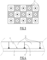
- the attachment surface 20 includes an inner region 26 extending away from the edges 22 , and a peripheral region 28 surrounding the inner region 26 and extending near the edges 22 , and a central region 30 extending in the middle of the attachment surface 20 , surrounded by the inner region 26 .
- the magnets 24 are placed on the peripheral region 28 and the central region 30 , the inner region 26 being devoid of magnets 24 .
- This arrangement makes it possible to maximize the holding power of the tile 16 , the stresses resulting from pulling out of the tile 16 being located in the vicinity of the edges 22 .
- the magnets 24 are arranged in a grid over the attachment surface 24 , for example a grid forming a checkerboard.
- Each magnet 24 is thus adjacent to at least one closest neighbor, for example to between one and four closest neighbors in the case of a checkerboard grid.
- Adjacent means that the magnets 24 are in contact by one respective lateral edge, or that their respective adjacent lateral edges are next to one another.
- each magnet 24 has a polarity oriented in a direction substantially orthogonal to the attachment surface 20 .
- Each of the closest neighbors of the magnet 24 has a polarity oriented in the direction opposite the polarity of the magnet 24 .
- the magnets 24 whereof the polarity is oriented toward the hull 12 are shown in white, and the magnets 24 whereof the polarity is oriented toward the outside are shown in gray.
- the proportion of magnets 24 whereof the polarity is oriented in one direction and the proportion of magnets 24 whereof the polarity is oriented in the opposite direction are substantially equal, advantageously equal.
- the material of the tiles 16 has advantageous properties of thermal insulation, absorption of electromagnetic waves, reduction of the hydrodynamic drag, or the like.
- the tiles 16 have a prism shape with a hexagonal base, which increases the holding power of the tile 16 .
- the shape of the base may have any geometry making it possible to ensure a desired coverage of the outer surface 14 of the hull 12 .
- the magnets 24 are embedded in the tile in the vicinity of the attachment surface 20 , for example at a distance of less than 5 mm from the attachment surface 20 .
- the magnets 24 are glued on the tile 16 at the attachment surface 20 .
- the magnets 24 are groups of permanent magnets in contact with or close to one another, having polarities oriented in a same direction, the groups of magnets being arranged in a grid identically to the magnets 24 described above.
- the magnets 24 are arranged in a disorderly manner on the attachment surface 20 , the proportion of magnets 24 whereof the polarity is oriented in one direction being substantially equal to the proportion of magnets 24 whereof the polarity is oriented in the opposite direction.
- the central region 30 is devoid of magnets 24 , the magnets 24 being positioned on the peripheral region 26 only.
- the magnets 24 are positioned on the entire attachment surface 20 .
- the polarities of the magnets form a non-right angle with the attachment surface 20 , or are tangential to the attachment surface 20 .
- the magnets 24 are not adjacent to their closest neighbors, but are separated by a constant pitch from each of their closest neighbors.
- edges 22 of each tile 16 are beveled and suitable for cooperating with nonslip ribs 32 extending over the outer surface 14 of the hull 12 . This makes it possible to increase the resistance of the tiles 16 to slipping along the outer surface 14 of the hull 12 .
- the hull device includes an active apparatus, for example a sprayer 34 , and an attachment slab 38 .
- the sprayer 34 is mounted by means of a foot 36 on the attachment slab 38 .
- the slab 38 defines an attachment surface 20 , extending on one side of the slab 38 opposite the foot 36 , and including the magnets 24 arranged in a grid as previously described.
- the active equipment is for example a sensor, a camera, an antenna, a signal apparatus or a tool.
- the hull device is a mobile device, for example a robot 50 for inspecting the hull 12 .
- the robot 50 comprises a housing 52 and tracks 54 .
- the housing 52 contains control electronics of the robot 50 , a drive motor of the tracks 54 , and communication means.
- the hull 52 is suitable for tightly insulating its contents from the outside, and includes a window 56 through which the sensors can take measurements, for example optical measurements.
- Each track 54 comprises a tread 58 positioned around at least two wheels 60 .
- the wheels 60 are set in rotation by the motor and drive the tread 58 , which is in contact with the outer surface 14 of the hull 12 .
- the attachment surface 20 extends over the tread 58 , such that part of the attachment surface 20 is constantly in contact with the outer surface 14 of the hull 12 .
- the magnets 24 are embedded in the tread 58 and flush with the surface of the tread 58 .
- the magnets 24 are glued to the surface of the tread 58 .
- the magnets 24 located on the part of the attachment surface 20 in contact with the hull 12 then keep the robot 50 against the hull 12 during the movement of the robot 50 .
- the robot 50 comprises wheels or movable feet in place of the tracks 58 , and the attachment surface 20 extends over an outer rolling surface of each wheel or below the movable feet.
- the robot 50 comprises a magnetized plate 70 on which the attachment surface 20 extends, located below the robot 50 , attaching the robot 50 to the hull 12 , as well as non-magnetized wheels 72 moving it.
- the magnetized plate 70 is not in direct contact with the hull 12 , but is positioned in the vicinity of the hull 12 , for example at a distance of less than 2 mm.
- the magnetized plate 70 then has an air gap with the hull 12 .
- the contact between the robot 50 and the hull 12 takes place via the wheels 72 , or via tracks or feet that are not magnetized, which ensures the movement of the robot 50 .
- the described hull device can be attached reversibly, and it is easy and inexpensive to install in terms of specific equipment and labor, since the attachment is done by magnets that are easy for one skilled in the art to manipulate.
- the hull device according to the invention is particularly advantageous in terms of magnetic signature.
- the alternating polarities of the magnets has the advantage both of generating a significant attraction force and minimizing the gradient of the magnetic field lines in the hull.
- the magnetization of the hull is modified on the surface and at several millimeters thick (in its depth), but much less significantly than a system including large magnets having or not having alternating polarities.
- the magnetization of the hull is modified very locally and on the surface, which leads to a very slight modification of the magnetic field several centimeters away from the hull, but does not modify the magnetic field at greater distances.
Landscapes
- Engineering & Computer Science (AREA)
- Aviation & Aerospace Engineering (AREA)
- Mechanical Engineering (AREA)
- Physics & Mathematics (AREA)
- Electromagnetism (AREA)
- Power Engineering (AREA)
- Manipulator (AREA)
- Hard Magnetic Materials (AREA)
- Toys (AREA)
- Catching Or Destruction (AREA)
Applications Claiming Priority (3)
| Application Number | Priority Date | Filing Date | Title |
|---|---|---|---|
| FR1701196 | 2017-11-20 | ||
| FR1701196A FR3073811B1 (fr) | 2017-11-20 | 2017-11-20 | Equipement de coque |
| PCT/EP2018/081786 WO2019097056A1 (fr) | 2017-11-20 | 2018-11-19 | Equipement de coque |
Publications (2)
| Publication Number | Publication Date |
|---|---|
| US20200283107A1 US20200283107A1 (en) | 2020-09-10 |
| US11634199B2 true US11634199B2 (en) | 2023-04-25 |
Family
ID=61655814
Family Applications (1)
| Application Number | Title | Priority Date | Filing Date |
|---|---|---|---|
| US16/765,244 Active 2038-11-28 US11634199B2 (en) | 2017-11-20 | 2018-11-19 | Hull device |
Country Status (9)
| Country | Link |
|---|---|
| US (1) | US11634199B2 (de) |
| EP (1) | EP3713841B1 (de) |
| JP (1) | JP7232830B2 (de) |
| KR (1) | KR102613246B1 (de) |
| AU (1) | AU2018368617B2 (de) |
| BR (1) | BR112020009392A2 (de) |
| ES (1) | ES3038158T3 (de) |
| FR (1) | FR3073811B1 (de) |
| WO (1) | WO2019097056A1 (de) |
Families Citing this family (4)
| Publication number | Priority date | Publication date | Assignee | Title |
|---|---|---|---|---|
| KR102376907B1 (ko) * | 2020-07-21 | 2022-03-22 | 대우조선해양 주식회사 | 선체 외부에 독립적으로 부착 가능한 계측기구 |
| KR200498650Y1 (ko) * | 2022-04-19 | 2024-12-20 | 주식회사 뉴로센스 | 차량의 내부에 설치되는 감지 센서 |
| KR102703044B1 (ko) * | 2022-10-31 | 2024-09-04 | 주식회사 에스아이웨어 | 선체 외판 이동용 자동 도장장치 |
| KR102703045B1 (ko) * | 2022-10-31 | 2024-09-04 | 주식회사 에스아이웨어 | 선체 외판 곡면을 인식하며 도장액을 분사하는 자동 도장장치 |
Citations (17)
| Publication number | Priority date | Publication date | Assignee | Title |
|---|---|---|---|---|
| JPS59122509U (ja) | 1983-02-07 | 1984-08-17 | 三菱重工業株式会社 | 喫水読取装置 |
| FR2568401A1 (fr) | 1984-07-26 | 1986-01-31 | Sauveplane Francois | Dispositif magnetique pour assembler, de maniere provisoire, deux elements, notamment des elements aptes a constituer un coffrage |
| US5038701A (en) * | 1990-03-23 | 1991-08-13 | Riddell Floyd A | Method and means for covering openings in hulls of damaged ships |
| WO1992004574A1 (en) | 1990-09-11 | 1992-03-19 | Environmental Emergency Seals Pty Limited | Apparatus and method of sealing ruptured tanks |
| US20020170481A1 (en) | 2001-05-18 | 2002-11-21 | Mcnamara George C. | Multi-functional cellular surface for underwater vehicles |
| US20090260556A1 (en) * | 2008-04-17 | 2009-10-22 | Ronald Clifford Sahr | Magnetically Attached Floor Covering for a Boat |
| WO2010078299A1 (en) | 2008-12-30 | 2010-07-08 | Sanford L.P. | Magnetic array for securing an object to a ferromagnetic surface |
| US20120255152A1 (en) | 2011-04-08 | 2012-10-11 | Evans Robert B | Surface flow enhancement device and method of using the same on a vehicle |
| JP2013177112A (ja) | 2012-02-09 | 2013-09-09 | Nippon Steel & Sumitomo Metal Corp | 磁性体移動車用車輪および磁性体移動車 |
| US20140077587A1 (en) * | 2012-09-14 | 2014-03-20 | Raytheon Company | Magnetic Track |
| US20140103169A1 (en) | 2012-10-16 | 2014-04-17 | Serpent And Dove - Applied Magnetics Pty Ltd | Magnetic Clamp |
| GB2510087A (en) | 2011-10-19 | 2014-07-23 | Republic Of Korea Korea Coast Guard Commissioner | Low-pressure liquid leakage prevention device |
| US20140230711A1 (en) | 2009-11-23 | 2014-08-21 | Searobotics Corporation | Mobile Operations Chassis with Controlled Magnetic Attraction to Ferrous Surfaces |
| GB2514626A (en) | 2013-06-01 | 2014-12-03 | Peter John Charles Spurgeon | An aquatic fender |
| JP2016196284A (ja) | 2015-04-02 | 2016-11-24 | ファン、ジョン ハ | 船舶破口封鎖装置及び船舶破口封鎖システム |
| US20170323715A1 (en) * | 2014-09-26 | 2017-11-09 | Elliott Chewins | Removable fluid barrier |
| US20190185119A1 (en) * | 2016-08-26 | 2019-06-20 | Bri Norhull As | Holding Means for Holding an Apparatus Against a Metallic Surface |
Family Cites Families (2)
| Publication number | Priority date | Publication date | Assignee | Title |
|---|---|---|---|---|
| US2958019A (en) * | 1956-09-17 | 1960-10-25 | Indiana General Corp | Magnetic pad assembly |
| KR101291150B1 (ko) * | 2011-07-15 | 2013-07-31 | 삼성중공업 주식회사 | 선체 벽면 작업용 로봇 및 그 제어방법 |
-
2017
- 2017-11-20 FR FR1701196A patent/FR3073811B1/fr active Active
-
2018
- 2018-11-19 AU AU2018368617A patent/AU2018368617B2/en not_active Ceased
- 2018-11-19 EP EP18800976.5A patent/EP3713841B1/de active Active
- 2018-11-19 US US16/765,244 patent/US11634199B2/en active Active
- 2018-11-19 KR KR1020207013653A patent/KR102613246B1/ko active Active
- 2018-11-19 JP JP2020527786A patent/JP7232830B2/ja active Active
- 2018-11-19 ES ES18800976T patent/ES3038158T3/es active Active
- 2018-11-19 BR BR112020009392-0A patent/BR112020009392A2/pt active Search and Examination
- 2018-11-19 WO PCT/EP2018/081786 patent/WO2019097056A1/fr not_active Ceased
Patent Citations (18)
| Publication number | Priority date | Publication date | Assignee | Title |
|---|---|---|---|---|
| JPS59122509U (ja) | 1983-02-07 | 1984-08-17 | 三菱重工業株式会社 | 喫水読取装置 |
| FR2568401A1 (fr) | 1984-07-26 | 1986-01-31 | Sauveplane Francois | Dispositif magnetique pour assembler, de maniere provisoire, deux elements, notamment des elements aptes a constituer un coffrage |
| US5038701A (en) * | 1990-03-23 | 1991-08-13 | Riddell Floyd A | Method and means for covering openings in hulls of damaged ships |
| WO1992004574A1 (en) | 1990-09-11 | 1992-03-19 | Environmental Emergency Seals Pty Limited | Apparatus and method of sealing ruptured tanks |
| JPH06504019A (ja) | 1990-09-11 | 1994-05-12 | ゴウルディング,デイル・エルヴィス | 破裂したタンクを封止する装置及び方法 |
| US20020170481A1 (en) | 2001-05-18 | 2002-11-21 | Mcnamara George C. | Multi-functional cellular surface for underwater vehicles |
| US20090260556A1 (en) * | 2008-04-17 | 2009-10-22 | Ronald Clifford Sahr | Magnetically Attached Floor Covering for a Boat |
| WO2010078299A1 (en) | 2008-12-30 | 2010-07-08 | Sanford L.P. | Magnetic array for securing an object to a ferromagnetic surface |
| US20140230711A1 (en) | 2009-11-23 | 2014-08-21 | Searobotics Corporation | Mobile Operations Chassis with Controlled Magnetic Attraction to Ferrous Surfaces |
| US20120255152A1 (en) | 2011-04-08 | 2012-10-11 | Evans Robert B | Surface flow enhancement device and method of using the same on a vehicle |
| GB2510087A (en) | 2011-10-19 | 2014-07-23 | Republic Of Korea Korea Coast Guard Commissioner | Low-pressure liquid leakage prevention device |
| JP2013177112A (ja) | 2012-02-09 | 2013-09-09 | Nippon Steel & Sumitomo Metal Corp | 磁性体移動車用車輪および磁性体移動車 |
| US20140077587A1 (en) * | 2012-09-14 | 2014-03-20 | Raytheon Company | Magnetic Track |
| US20140103169A1 (en) | 2012-10-16 | 2014-04-17 | Serpent And Dove - Applied Magnetics Pty Ltd | Magnetic Clamp |
| GB2514626A (en) | 2013-06-01 | 2014-12-03 | Peter John Charles Spurgeon | An aquatic fender |
| US20170323715A1 (en) * | 2014-09-26 | 2017-11-09 | Elliott Chewins | Removable fluid barrier |
| JP2016196284A (ja) | 2015-04-02 | 2016-11-24 | ファン、ジョン ハ | 船舶破口封鎖装置及び船舶破口封鎖システム |
| US20190185119A1 (en) * | 2016-08-26 | 2019-06-20 | Bri Norhull As | Holding Means for Holding an Apparatus Against a Metallic Surface |
Non-Patent Citations (4)
| Title |
|---|
| French Search Report, FR 1701196, dated Jul. 3, 2018. |
| International Search Report, PCT/EP2018/081786, dated Jan. 15, 2019. |
| Kand J Blog "Halbach Arrays" https://www.kjmagnetics.com/blog.asp?p=halbach-arrays, published Nov. 27, 2016, retrieved Sep. 22, 2021 (Year: 2016). * |
| Nautical Expo "Polypropylene floor coverings" https://www.nauticexpo.com/boat-manufacturer/polypropylene-floor-covering-38122.html, published Aug. 11, 2017, retrieved Sep. 22, 2021 (Year: 2017). * |
Also Published As
| Publication number | Publication date |
|---|---|
| EP3713841C0 (de) | 2025-06-04 |
| FR3073811B1 (fr) | 2020-11-20 |
| FR3073811A1 (fr) | 2019-05-24 |
| KR102613246B1 (ko) | 2023-12-12 |
| BR112020009392A2 (pt) | 2020-11-03 |
| AU2018368617B2 (en) | 2024-03-07 |
| KR20200083489A (ko) | 2020-07-08 |
| WO2019097056A1 (fr) | 2019-05-23 |
| JP2021503410A (ja) | 2021-02-12 |
| US20200283107A1 (en) | 2020-09-10 |
| EP3713841B1 (de) | 2025-06-04 |
| AU2018368617A1 (en) | 2020-05-28 |
| EP3713841A1 (de) | 2020-09-30 |
| ES3038158T3 (en) | 2025-10-09 |
| JP7232830B2 (ja) | 2023-03-03 |
Similar Documents
| Publication | Publication Date | Title |
|---|---|---|
| US11634199B2 (en) | Hull device | |
| US10404143B2 (en) | Apparatus for detecting angular displacement, system for controlling rotation angle of motor, gimbal, and aircraft | |
| US9329296B2 (en) | Underwater detector and method for underwater detection | |
| CA2401587A1 (en) | Apparatus for deploying a load to an underwater target position with enhanced accuracy and a method to control such apparatus | |
| US20180232874A1 (en) | Inspection vehicle | |
| KR101774922B1 (ko) | 선박 방오 장치 | |
| CN110703197A (zh) | 一种侧向测量式倒置超短基线收发换能器及其工作方式 | |
| WO2016126644A1 (en) | Halbach array assembly | |
| CN113165537A (zh) | 用于感应充电水上交通工具的功率传输装置和停泊区 | |
| AU2019399929B2 (en) | Demagnetization and signature measurement system | |
| ES2369724T3 (es) | Dispositivo para la detección de emisiones acústicas. | |
| KR101831179B1 (ko) | 무인 비행체를 이용한 파형 강판의 변위 측정 시스템 | |
| JP7582745B2 (ja) | 吸着状態判別装置、吸着状態判別装置を備える吸着装置、吸着装置を備える無人飛行体またはロボット、吸着状態判別方法、吸着装置の制御方法、および、吸着状態判別プログラム | |
| WO2011162893A3 (en) | Finishing technique | |
| EP3360771B1 (de) | Inspektionsfahrzeug | |
| KR101672898B1 (ko) | 센서를 포함하는 자기부상 열차 | |
| CA2490839A1 (en) | Apparatus for deploying a load to an underwater target position with enhanced accuracy and a method to control such apparatus | |
| KR101648036B1 (ko) | 이중 어레이 작동기에 의한 국부 진동 제어 장치 및 방법 | |
| JPWO2019097056A5 (de) | ||
| KR20150068094A (ko) | 보조 갭 센서를 갖는 자기부상 시스템 | |
| JPH10227848A (ja) | 大型浮体の体壁位置測定装置 | |
| CN107505703A (zh) | 一种反射镜偏转装置 | |
| KR20130062530A (ko) | 장비 탑재용 가이드 피스와 그 탑재방법 |
Legal Events
| Date | Code | Title | Description |
|---|---|---|---|
| FEPP | Fee payment procedure |
Free format text: ENTITY STATUS SET TO UNDISCOUNTED (ORIGINAL EVENT CODE: BIG.); ENTITY STATUS OF PATENT OWNER: LARGE ENTITY |
|
| AS | Assignment |
Owner name: NAVAL GROUP, FRANCE Free format text: ASSIGNMENT OF ASSIGNORS INTEREST;ASSIGNORS:REYNARD, FRANCOIS;CAVALLERA, DIDIER;DEMILIER, LAURENT;SIGNING DATES FROM 20200408 TO 20200428;REEL/FRAME:053254/0074 |
|
| STPP | Information on status: patent application and granting procedure in general |
Free format text: DOCKETED NEW CASE - READY FOR EXAMINATION |
|
| STPP | Information on status: patent application and granting procedure in general |
Free format text: NON FINAL ACTION MAILED |
|
| STPP | Information on status: patent application and granting procedure in general |
Free format text: RESPONSE TO NON-FINAL OFFICE ACTION ENTERED AND FORWARDED TO EXAMINER |
|
| STPP | Information on status: patent application and granting procedure in general |
Free format text: FINAL REJECTION MAILED |
|
| STPP | Information on status: patent application and granting procedure in general |
Free format text: DOCKETED NEW CASE - READY FOR EXAMINATION |
|
| STPP | Information on status: patent application and granting procedure in general |
Free format text: NON FINAL ACTION MAILED |
|
| STPP | Information on status: patent application and granting procedure in general |
Free format text: RESPONSE TO NON-FINAL OFFICE ACTION ENTERED AND FORWARDED TO EXAMINER |
|
| STCF | Information on status: patent grant |
Free format text: PATENTED CASE |