US11631668B2 - Current concentration-suppressed electronic circuit, and semiconductor module and semiconductor apparatus containing the same - Google Patents
Current concentration-suppressed electronic circuit, and semiconductor module and semiconductor apparatus containing the same Download PDFInfo
- Publication number
- US11631668B2 US11631668B2 US17/085,696 US202017085696A US11631668B2 US 11631668 B2 US11631668 B2 US 11631668B2 US 202017085696 A US202017085696 A US 202017085696A US 11631668 B2 US11631668 B2 US 11631668B2
- Authority
- US
- United States
- Prior art keywords
- terminal
- diodes
- sbd
- path
- diode
- Prior art date
- Legal status (The legal status is an assumption and is not a legal conclusion. Google has not performed a legal analysis and makes no representation as to the accuracy of the status listed.)
- Active, expires
Links
Images


Classifications
-
- H10W90/00—
-
- H—ELECTRICITY
- H10—SEMICONDUCTOR DEVICES; ELECTRIC SOLID-STATE DEVICES NOT OTHERWISE PROVIDED FOR
- H10D—INORGANIC ELECTRIC SEMICONDUCTOR DEVICES
- H10D84/00—Integrated devices formed in or on semiconductor substrates that comprise only semiconducting layers, e.g. on Si wafers or on GaAs-on-Si wafers
- H10D84/201—Integrated devices formed in or on semiconductor substrates that comprise only semiconducting layers, e.g. on Si wafers or on GaAs-on-Si wafers characterised by the integration of only components covered by H10D1/00 or H10D8/00, e.g. RLC circuits
- H10D84/204—Integrated devices formed in or on semiconductor substrates that comprise only semiconducting layers, e.g. on Si wafers or on GaAs-on-Si wafers characterised by the integration of only components covered by H10D1/00 or H10D8/00, e.g. RLC circuits of combinations of diodes or capacitors or resistors
- H10D84/221—Integrated devices formed in or on semiconductor substrates that comprise only semiconducting layers, e.g. on Si wafers or on GaAs-on-Si wafers characterised by the integration of only components covered by H10D1/00 or H10D8/00, e.g. RLC circuits of combinations of diodes or capacitors or resistors of only diodes
-
- H01L27/0814—
-
- H—ELECTRICITY
- H01—ELECTRIC ELEMENTS
- H01L—SEMICONDUCTOR DEVICES NOT COVERED BY CLASS H10
- H01L23/00—Details of semiconductor or other solid state devices
- H01L23/52—Arrangements for conducting electric current within the device in operation from one component to another, i.e. interconnections, e.g. wires, lead frames
- H01L23/538—Arrangements for conducting electric current within the device in operation from one component to another, i.e. interconnections, e.g. wires, lead frames the interconnection structure between a plurality of semiconductor chips being formed on, or in, insulating substrates
- H01L23/5386—Geometry or layout of the interconnection structure
-
- H—ELECTRICITY
- H01—ELECTRIC ELEMENTS
- H01L—SEMICONDUCTOR DEVICES NOT COVERED BY CLASS H10
- H01L23/00—Details of semiconductor or other solid state devices
- H01L23/58—Structural electrical arrangements for semiconductor devices not otherwise provided for, e.g. in combination with batteries
- H01L23/64—Impedance arrangements
- H01L23/645—Inductive arrangements
-
- H01L29/1608—
-
- H—ELECTRICITY
- H02—GENERATION; CONVERSION OR DISTRIBUTION OF ELECTRIC POWER
- H02M—APPARATUS FOR CONVERSION BETWEEN AC AND AC, BETWEEN AC AND DC, OR BETWEEN DC AND DC, AND FOR USE WITH MAINS OR SIMILAR POWER SUPPLY SYSTEMS; CONVERSION OF DC OR AC INPUT POWER INTO SURGE OUTPUT POWER; CONTROL OR REGULATION THEREOF
- H02M7/00—Conversion of AC power input into DC power output; Conversion of DC power input into AC power output
- H02M7/003—Constructional details, e.g. physical layout, assembly, wiring or busbar connections
-
- H—ELECTRICITY
- H02—GENERATION; CONVERSION OR DISTRIBUTION OF ELECTRIC POWER
- H02M—APPARATUS FOR CONVERSION BETWEEN AC AND AC, BETWEEN AC AND DC, OR BETWEEN DC AND DC, AND FOR USE WITH MAINS OR SIMILAR POWER SUPPLY SYSTEMS; CONVERSION OF DC OR AC INPUT POWER INTO SURGE OUTPUT POWER; CONTROL OR REGULATION THEREOF
- H02M7/00—Conversion of AC power input into DC power output; Conversion of DC power input into AC power output
- H02M7/42—Conversion of DC power input into AC power output without possibility of reversal
- H02M7/44—Conversion of DC power input into AC power output without possibility of reversal by static converters
- H02M7/48—Conversion of DC power input into AC power output without possibility of reversal by static converters using discharge tubes with control electrode or semiconductor devices with control electrode
-
- H—ELECTRICITY
- H10—SEMICONDUCTOR DEVICES; ELECTRIC SOLID-STATE DEVICES NOT OTHERWISE PROVIDED FOR
- H10D—INORGANIC ELECTRIC SEMICONDUCTOR DEVICES
- H10D62/00—Semiconductor bodies, or regions thereof, of devices having potential barriers
- H10D62/80—Semiconductor bodies, or regions thereof, of devices having potential barriers characterised by the materials
- H10D62/83—Semiconductor bodies, or regions thereof, of devices having potential barriers characterised by the materials being Group IV materials, e.g. B-doped Si or undoped Ge
- H10D62/832—Semiconductor bodies, or regions thereof, of devices having potential barriers characterised by the materials being Group IV materials, e.g. B-doped Si or undoped Ge being Group IV materials comprising two or more elements, e.g. SiGe
- H10D62/8325—Silicon carbide
-
- H10W40/255—
-
- H10W44/501—
-
- H10W70/611—
-
- H10W70/65—
-
- H10W72/50—
-
- H10W90/701—
-
- H10W72/07552—
-
- H10W72/07553—
-
- H10W72/527—
-
- H10W72/534—
-
- H10W72/536—
-
- H10W72/537—
-
- H10W72/5473—
-
- H10W72/5475—
-
- H10W72/926—
-
- H10W76/157—
-
- H10W76/47—
-
- H10W90/753—
Definitions
- the present invention relates to an electronic circuit, a semiconductor module, and a semiconductor apparatus.
- a semiconductor apparatus includes a substrate provided with a semiconductor element such as an insulated gate bipolar transistor (IGBT), a power metal oxide semiconductor field effect transistor (power MOSFET), or a free wheeling diode (FWD) and is used for an inverter apparatus or the like.
- a semiconductor element such as an insulated gate bipolar transistor (IGBT), a power metal oxide semiconductor field effect transistor (power MOSFET), or a free wheeling diode (FWD) and is used for an inverter apparatus or the like.
- IGBT insulated gate bipolar transistor
- power MOSFET power metal oxide semiconductor field effect transistor
- FWD free wheeling diode
- the semiconductor apparatus described in patent document 1 includes a plurality of IGBTs and diodes connected in parallel. In this semiconductor apparatus, a flowing current is distributed between the individual IGBTs connected in parallel, and thus this semiconductor apparatus is suitable for use in an inverter apparatus that requires a heavy current.
- the semiconductor apparatus described in patent document 1 includes a miniature metal plate on which the IGBTs and the diodes are mounted. Hence, the parasitic inductance of the metal plate is minimized, thereby minimizing a surge voltage generated when operating the inverter apparatus.
- IGBTs and diodes have individual differences associated with manufacturing processes. With respect to, for example, patent document 1, forward voltages (VF) on the diodes connected in parallel are different, and ON voltages (V ON ) on the IGBTs connected in parallel are also different. Due to the individual differences, a current is concentrated on certain ones of the diodes or IGBTs when operating the inverter apparatus. The certain semiconductor elements having a current concentrated thereon generate more heat than the other semiconductor elements and could possibly be broken due to abnormal heat generation.
- the present invention was created in view of such facts, and an object of the invention is to provide an electronic circuit, semiconductor module, and semiconductor apparatus that can suppress a current from being concentrated on certain semiconductor elements among a plurality of semiconductor elements connected in parallel.
- An electronic circuit in accordance with an aspect of the present invention includes a plurality of diodes connected in parallel and including a first diode and a second diode that has applied thereto a higher forward voltage than the first diode, wherein an inductance of a first path from a first terminal via the first diode to a second terminal is larger than an inductance of a second path from the first terminal via the second diode to the second terminal.
- a semiconductor module in accordance with an aspect of the present invention is provided with an electronic circuit that includes a plurality of diodes connected in parallel and including a first diode and a second diode that has applied thereto a higher forward voltage than the first diode.
- the semiconductor module is such that an inductance of a wiring member forming a first path from a first terminal via the first diode to a second terminal is larger than an inductance of a wiring member forming a second path from the first terminal via the second diode to the second terminal.
- a semiconductor apparatus in accordance with an aspect of the present invention includes a plurality of said semiconductor modules, the plurality of semiconductor modules being connected in parallel between a pair of terminals. Paths each extending from one to another of the pair of terminals via each of the plurality of semiconductor modules are such that paths extending via semiconductor modules that have a lower forward voltage applied thereto have a larger inductance.
- An electronic circuit in accordance with another aspect of the present invention includes a plurality of switching elements connected in parallel and including a first switching element and a second switching element that has applied thereto a higher ON voltage than the first switching element, wherein an inductance of a first path from a first terminal via the first switching element to a second terminal is larger than an inductance of a second path from the first terminal via the second switching element to the second terminal.
- an electronic circuit, a semiconductor module, and a semiconductor apparatus can suppress a current from being concentrated on certain semiconductor elements among a plurality of semiconductor elements connected in parallel.
- FIG. 1 is a schematic plan view illustrating a semiconductor module in accordance with an embodiment of the present invention
- FIG. 2 is an equivalent circuit schematic illustrating a semiconductor module in accordance with an embodiment of the invention
- FIG. 3 A conceptually illustrates relationships in length between bonding wires connecting a plurality of diodes connected in parallel to electrodes on a circuit board in an embodiment of the invention
- FIG. 3 B conceptually illustrates relationships in length between bonding wires connecting a plurality of diodes connected in parallel to electrodes on a circuit board in an embodiment of the invention
- FIG. 4 conceptually illustrates relationships in length between bonding wires connecting a plurality of diodes connected in parallel to electrodes on a circuit board in an embodiment of the invention
- FIG. 5 conceptually illustrates magnitude relationships between cross-sectional areas of bonding wires connecting a plurality of diodes connected in parallel to electrodes on a circuit board in an embodiment of the invention
- FIG. 6 conceptually illustrates magnitude relationships between cross-sectional areas of bonding wires connecting a plurality of diodes connected in parallel to electrodes on a circuit board in an embodiment of the invention
- FIG. 7 conceptually illustrates relationships in length between wiring patterns connected to a plurality of diodes in an embodiment of the invention
- FIG. 8 conceptually illustrates magnitude relationships between cross-sectional areas of wiring patterns connected to a plurality of diodes in an embodiment of the invention
- FIG. 9 conceptually illustrates relationships in length between wiring patterns connected to a plurality of diodes in an embodiment of the invention and magnitude relationships between cross-sectional areas of these wiring patterns;
- FIG. 10 conceptually illustrates relationships in length between bonding wires connecting a plurality of diodes connected in parallel to electrodes on a circuit board in an embodiment of the invention.
- FIG. 11 schematically illustrates a semiconductor apparatus in accordance with an embodiment of the invention.
- FIGS. 1 and 2 are respectively a schematic plan view and an equivalent circuit schematic illustrating a semiconductor module 1 in accordance with an embodiment of the invention.
- the semiconductor module 1 in accordance with the embodiment of the invention is nothing but an example, and the invention is not limited to this and can have changes made thereto, as appropriate.
- the semiconductor module 1 which is applied to, for example, a power module, includes a baseboard 10 , a layered substrate 2 disposed over the baseboard 10 , and a case member 12 accommodating the layered substrate 2 , as depicted in FIG. 1 .
- the baseboard 10 is a metal plate shaped like a quadrangle when seen in a plan view and formed from, for example, copper, aluminum, or an alloy thereof.
- the baseboard 10 serves as a heat dissipation plate that dissipates heat from the layered substrate 2 or electronic components mounted on the layered substrate 2 to the outside.
- the case member 12 is a resin frame body shaped like a rectangle having sides along the outer shape of the baseboard 10 and bonded to, for example, the baseboard 10 .
- a space surrounded by the baseboard 10 and the case member 12 is filled with a sealing resin (not illustrated).
- the layered substrate 2 and electronic components mounted thereon are sealed within the space by the sealing resin.
- the layered substrate 2 may be formed from a direct bonded aluminum (DBA) substrate, a direct bonded copper (DBC) substrate, or an active metal brazing (AMB) substrate.
- the layered substrate 2 includes an insulation layer 20 formed from an insulator such as ceramic, e.g., a ceramic material of alumina (Al 2 O 3 ), aluminum nitride (AlN), or silicon nitride (Si 3 N 4 ).
- a first circuit board 21 , a second circuit board 22 , and a third circuit board 23 are formed over an upper surface of the insulation layer 20 .
- the circuit boards are metal layers of copper foil or the like, formed like islands over the insulation layer 20 , and electrically insulated from each other.
- a P terminal (positive potential point) 31 , a U terminal (intermediate potential point) 32 , and an N terminal (negative potential point) 33 are respectively disposed on (connected to) the first circuit board 21 , the second circuit board 22 , and the third circuit board 23 with a bonding material such as solder between the terminals and the circuit boards.
- the P terminal 31 , the U terminal 32 , and the N terminal are external connection terminals via which a principal current is input/output to/from the semiconductor module 1 .
- a plurality of electronic components are disposed over the first circuit board 21 and the second circuit board 22 with a bonding material such as solder therebetween.
- switching elements MOS 1 -MOS 4 and diodes SBD 1 -SBD 4 are disposed over the first circuit board 21 with a bonding material therebetween.
- Switching elements MOS 5 -MOS 8 and diodes SBD 5 -SBD 8 are disposed over the second circuit board 22 with a bonding material therebetween.
- the switching elements MOS 1 -MOS 8 may be semiconductor switching elements produced using silicon (Si), silicon carbide (SiC), or gallium carbide (GaN), in particular power MOSFETs.
- the switching elements MOS 1 -MOS 8 are power MOSFETs, these switching elements each have, on a back side thereof, a drain terminal to serve as a main electrode and, on a front side thereof, a gate electrode and a source electrode to serve as a main electrode.
- the switching elements MOS 1 -MOS 8 may include body diodes parasitic in the power MOSFETs.
- the body diodes are connected in antiparallel to the power MOSFETs and each have a cathode electrode provided on a back side thereof and an anode electrode provided on a front side thereof.
- the switching elements MOS 1 -MOS 8 may be switching elements having another structure, such as IGBTs. When the switching elements MOS 1 -MOS 8 are IGBTs, these switching elements each have, on a back side thereof, a collector terminal to serve as a main electrode and, on a front side thereof, a gate electrode and an emitter electrode to serve as a main electrode.
- the switching elements MOS 1 -MOS 8 may each be a reverse-conducting IGBT (RC-IGBT) provided by forming an IGBT and a diode into one chip.
- the diodes in this case are connected in antiparallel to the IGBTs and each have a cathode electrode provided on a back side thereof and an anode electrode provided on a front side thereof.
- the switching elements MOS 1 -MOS 4 are connected in parallel.
- the drain electrodes of the switching elements MOS 1 -MOS 4 are disposed over the first circuit board 21 with a bonding material such as solder therebetween and electrically connected to the P terminal 31 .
- the source electrodes are electrically connected to the second circuit board 22 by bonding wires and electrically connected to the U terminal 32 .
- the gate electrodes of the switching elements MOS 1 -MOS 4 are connected by one bonding wire.
- the one bonding wire connecting the gate electrodes is electrically connected to a terminal member 13 buried in the case member 12 . While a voltage from the terminal member 13 that exceeds a predetermined threshold is being applied to the gate electrodes, the switching elements MOS 1 -MOS 4 are turned on, thereby causing a current to flow from the drain electrodes to the source electrodes. While a voltage from the terminal member 13 that exceeds the predetermined threshold is not applied to the gate electrodes, the switching elements MOS 1 -MOS 4 are turned off, thereby interrupting a current from the drain electrodes to the source electrodes.
- the switching elements MOS 5 -MOS 8 are also connected in parallel.
- the drain electrodes of the switching elements MOS 5 -MOS 8 are disposed over the second circuit board 22 with a bonding material such as solder therebetween and electrically connected to the U terminal 32 .
- the source electrodes are electrically connected to the third circuit board 23 by bonding wires and electrically connected to the N terminal 33 .
- the gate electrodes of the switching elements MOS 5 -MOS 8 are also connected by one bonding wire.
- the one bonding wire connecting the gate electrodes is electrically connected to a terminal member 14 buried in the case member 12 by a control circuit board. While a voltage from the terminal member 14 that exceeds a predetermined threshold is being applied to the gate electrodes, the switching elements MOS 5 -MOS 8 are turned on, thereby causing a current to flow from the drain electrodes to the source electrodes. While a voltage from the terminal member 14 that exceeds the predetermined threshold is not applied to the gate electrodes, the switching elements MOS 5 -MOS 8 are turned off, thereby interrupting a current from the drain electrodes to the source electrodes.
- the wirings for the source electrodes and the third circuit board 23 and the wirings for the gate electrodes and the control circuit board are not limited to bonding wires and may be replaced with other conductive wiring members such as ribbon wires or lead frames.
- the diodes SBD 1 -SBD 8 are diodes produced using SiC, in particular, Schottky barrier diodes.
- the diodes SBD 1 -SBD 8 may be produced using Si or SiC. Some of or all of the diodes SBD 1 -SBD 8 may be replaced with diodes having another structure such as junction barrier Schottky (JBS) diodes, merged PN Schottky (MPS) diodes, or PN diodes.
- JBS junction barrier Schottky
- MPS merged PN Schottky
- the diodes SBD 1 -SBD 8 may be diodes installed in RC-IGBTs.
- the diodes SBD 1 -SBD 8 are not limited to Schottky barrier diodes and may each have a different configuration.
- the diodes SBD 1 -SBD 8 each include a cathode electrode provided on the back side thereof as a main electrode and an anode electrode provided on the front side thereof as a main electrode.
- the diodes SBD 1 -SBD 4 are a plurality of diodes connected in parallel and including a first diode and a second diode that has applied thereto a higher forward voltage than the first diode.
- the diodes SBD 5 -SBD 8 are also a plurality of diodes connected in parallel and including a first diode and a second diode that has applied thereto a higher forward voltage than the first diode.
- a forward voltage is a voltage generated when a forward current flows through a diode.
- a forward voltage may be a voltage generated between an anode electrode and a cathode electrode when a rated current flows from the anode electrode to the cathode electrode.
- the diodes SBD 1 -SBD 4 are connected in parallel to the switching elements MOS 1 -MOS 4 , respectively. More specifically, the diodes SBD 1 -SBD 4 are free wheeling diodes (FWDs) and connected in antiparallel to the switching elements MOS 1 -MOS 4 , respectively.
- the anode electrodes of the diodes SBD 1 -SBD 4 are electrically connected to the U terminal 32 , and the cathode electrodes thereof are electrically connected to the P terminal 31 .
- symbols P 1 -P 4 respectively denote paths from the U terminal 32 via the diodes SBD 1 -SBD 4 to the P terminal 31 .
- the paths P 1 -P 4 are respectively formed from wiring members W 1 A -W 4 A electrically connecting the U terminal 32 to the anode electrodes of the diodes SBD 1 -SBD 4 and wiring members W 1 B -W 4 B electrically connecting the cathode electrodes of the diodes SBD 1 -SBD 4 to the P terminal 31 .
- Symbols L 1 A -L 4 A respectively denote inductances parasitic in portions of the paths P 1 -P 4 between the U terminal 32 and the anode electrodes of the diodes SBD 1 -SBD 4 (i.e., parasitic in the wiring members W 1 A -W 4 A ).
- Symbols L 1 B -L 4 B respectively denote inductances parasitic in portions of the paths P 1 -P 4 between the P terminal 31 and the cathode electrodes of the diodes SBD 1 -SBD 4 (i.e., parasitic in the wiring members W 1 B -W 4 B ).
- the wiring members W 1 A -W 4 A depicted in FIG. 2 respectively include wiring patterns on the second circuit board 22 that connect the U terminal 32 to electrodes T 1 -T 4 on the second circuit board 22 and bonding wires BW 1 -BW 4 that connect the electrodes T 1 -T 4 to the anode electrodes of the diodes SBD 1 -SBD 4 .
- the wiring members W 1 B -W 4 B depicted in FIG. 2 respectively include wiring patterns on the first circuit board 21 that connect the cathode electrodes of the diodes SBD 1 -SBD 4 to the P terminal 31 . Illustration of these wiring patterns is omitted to avoid complicating the figures. Note that the bonding wires BW 1 -BW 4 may be replaced with other conductive wiring members such as ribbon wires or lead frames.
- the diodes SBD 5 -SBD 8 are connected in parallel to the switching elements MOS 5 -MOS 8 , respectively. More specifically, the diodes SBD 5 -SBD 8 are FWDs and connected in antiparallel to the switching elements MOS 5 -MOS 8 , respectively.
- the anode electrodes of the diodes SBD 5 -SBD 8 are connected to the N terminal 33 , and the cathode electrodes thereof are connected to the U terminal 32 .
- symbols P 5 -P 8 respectively denote paths from the N terminal 33 via the diodes SBD 5 -SBD 8 to the U terminal 32 .
- the paths P 5 -P 8 are respectively formed from wiring members W 5 A -W 8 A connecting the N terminal 33 to the anode electrodes of the diodes SBD 5 -SBD 8 and wiring members W 5 B -W 8 B connecting the cathode electrodes of the diodes SBD 5 -SBD 8 to the U terminal 32 .
- Symbols L 5 A -L 8 A respectively denote inductances parasitic in portions of the paths P 5 -P 8 between the N terminal 33 and the anode electrodes of the diodes SBD 5 -SBD 8 (i.e., parasitic in the wiring members W 5 A -W 8 A ).
- Symbols L 5 B -L 8 B respectively denote inductances parasitic in portions of the paths P 1 -P 4 between the cathode electrodes of the diodes SBD 5 -SBD 8 and the U terminal 32 (i.e., parasitic in the wiring members W 5 B -W 8 B ).
- the wiring members W 5 A -W 8 A depicted in FIG. 2 respectively include wiring patterns on the third circuit board 23 that connect the N terminal 33 to electrodes T 5 -T 8 on the third circuit board 23 and bonding wires BW 5 -BW 8 that connect the electrodes T 5 -T 8 to the anode electrodes of the diodes SBD 5 -SBD 8 .
- the wiring members W 5 B -W 8 B depicted in FIG. 2 respectively include wiring patterns on the second circuit board 22 that connect the cathode electrodes of the diodes SBD 5 -SBD 8 to the U terminal 32 . Illustration of these wiring patterns is also omitted to avoid complicating the figures. Note that the bonding wires BW 5 -BW 8 may be replaced with other conductive wiring members such as ribbon wires or lead frames.
- Symbols BD 1 -BD 8 in FIG. 2 respectively denote body diodes parasitic in the switching elements MOS 1 -MOS 8 . As depicted in FIG. 2 , the diodes BD 1 -BD 8 are respectively connected in antiparallel to channels of the switching elements MOS 1 -MOS 8 .
- the semiconductor module 1 which is configured as described above involves a period in which a current flows in reverse from the negative-potential side to the positive-potential side in accordance with the switching elements MOS 1 -MOS 8 being turned on or off.
- the diodes SBD 1 -SBD 8 i.e., Schottky barrier diodes connected in antiparallel to the switching elements MOS 1 -MOS 8 , have applied thereto a lower forward voltage than the diodes BD 1 -BD 8 , i.e., body diodes parasitic in the switching elements MOS 1 -MOS 8 .
- a current flowing from the U terminal 32 to the P terminal 31 flows through the diodes SBD 1 -SBD 4 , as long as an applied voltage does not exceed the forward voltages specific to the diodes BD 1 -BD 4 .
- a current flowing from the N terminal 33 to the U terminal 32 flows through the diodes SBD 5 -SBD 8 , as long as an applied voltage does not exceed the forward voltages specific to the diodes BD 5 -BD 8 .
- the switching elements MOS 1 -MOS 8 are power MOSFETs produced using SiC.
- the forward voltage on the diodes BD 1 -BD 8 parasitic in the switching elements MOS 1 -MOS 8 will increases with a time of current carrying and thus could cause degradation due to the current carrying, thereby breaking the switching elements MOS 1 -MOS 8 .
- the diodes SBD 1 -SBD 8 which have a low forward voltage applied thereto, are connected in parallel to the diodes BD 1 -BD 8 , thereby making a current unlikely to flow through the diodes BD 1 -BD 8 .
- degradation of the diodes BD 1 -BD 8 caused by current carrying is suppressed so that the switching elements MOS 1 -MOS 8 can have a higher long-term reliability.
- the diodes SBD 1 -SBD 8 have the same structure but have individual differences associated with manufacturing processes. Accordingly, forward voltages on the diodes SBD 1 -SBD 8 have variations.
- a current will typically be concentrated more on diodes for which a lower forward voltage has been set. If a current flowing from the U terminal 32 to the P terminal 31 is concentrated on the diode for which the lowest forward voltage has been set among the diodes SBD 1 -SBD 4 , this diode will generate more heat than the other diodes due to the current concentration and could possibly be broken due to abnormal heat generation.
- the semiconductor module 1 is configured to suppress a current from being concentrated on certain diodes therein so as to prevent these diodes from being broken due to abnormal heat generation as described above.
- forward voltages are measured in advance for four Schottky barrier diodes so as to attain the configuration described above.
- the Schottky barrier diode for which the lowest forward voltage has been calculated is disposed in the path P 1
- the other Schottky barrier diodes are disposed in the paths P 2 -P 4 in ascending order of forward voltage.
- the diodes SBD 1 -SBD 4 are such that diodes denoted by a symbol with a smaller value have a lower forward voltage applied thereto.
- the semiconductor module 1 in accordance with embodiments is such that paths in which Schottky barrier diodes that have a lower forward voltage applied thereto are disposed among the paths P 1 -P 4 connected in parallel have a larger parasitic inductance.
- the parasitic inductance of the path P 1 i.e., wiring members W 1 A and W 1 B
- inductance (L 1 A +L 1 B ) is the largest among the parasitic inductances of the paths P 1 -P 4
- the parasitic inductances of the paths P 2 -P 4 i.e., wiring members W 2 A and W 2 B , wiring members W 3 A and W 3 B , and wiring members W 4 A and W 4 B
- the paths P 1 -P 4 are such
- the semiconductor module 1 includes an electronic circuit wherein the inductance of a first path (e.g., path P 1 ) from a first terminal (e.g., U terminal 32 ) via a first diode (e.g., diode SBD 1 ) to a second terminal (e.g., P terminal 31 ) is larger than the inductance of a second path (e.g., path P 2 ) from the first terminal via a second diode (e.g., diode SBD 2 ) to the second terminal.
- a first path e.g., path P 1
- a first diode e.g., diode SBD 1
- P terminal 31 e.g., P terminal 31
- the semiconductor module 1 also satisfies at least one of the following conditions (1)-(4) so as to arrange the paths P 1 -P 4 such that paths denoted by a symbol with a lower value have a larger parasitic inductance.
- first conductive wire The total length of a bonding wire forming one path
- second conductive wire The first conductive wire has a smaller cross-sectional area than the second conductive wire.
- first wiring pattern The total length of a wiring pattern forming one path
- second wiring pattern The total length of a wiring pattern forming one path
- first wiring pattern is greater than that of a wiring pattern forming another path in which a Schottky barrier diode is disposed and to which a forward voltage higher than that applied to the one path is applied
- second wiring pattern The first wiring pattern has a smaller cross-sectional area than the second wiring pattern.
- the conditions (1) and (2) indicate conditions for allowing the first conductive wire to have a larger parasitic inductance than the second conductive wire.
- the conditions (3) and (4) indicate conditions for allowing the first wiring pattern to have a larger parasitic inductance than the second wiring pattern.
- FIGS. 3 A, 3 B, and 4 conceptually illustrate the condition (1). As depicted in FIGS. 3 A, 3 B, and 4 , the bonding wires BW 1 -BW 4 are arranged such that bonding wires denoted by a symbol with a lower value have a greater total length.
- the diodes SBD 1 -SBD 4 are arranged in line in this order on the first circuit board 21 .
- the second circuit board 22 is formed on a side close to the diode SBD 4 to which a high forward voltage is applied.
- the diodes SBD 1 -SBD 4 are electrically connected to the electrodes T 1 -T 4 of the second circuit board 22 by the bonding wires BW 1 -BW 4 , respectively.
- the diodes SBD 1 -SBD 4 are arranged such that diodes denoted by a symbol with a smaller value (diodes to which a lower forward voltage is applied) are positioned farther from a corresponding electrode among the electrodes T 1 -T 4 .
- the bonding wires BW 1 -BW 4 are such that bonding wires denoted by a symbol with a lower value have a greater total length.
- the total length of the bonding wire BW 1 forming the path P 1 in which the diode SBD 1 is disposed may be greater than that of the bonding wire BW 2 forming the path P 2 in which the diode SBD 2 that has applied thereto a higher forward voltage than the diode SBD 1 is disposed.
- the bonding wires BW 1 -BW 4 are such that bonding wires denoted by a symbol with a lower value have a larger parasitic inductance.
- the paths P 1 -P 4 which respectively include the bonding wires BW 1 -BW 4 , are such that paths denoted by a symbol with a lower value have a larger parasitic inductance.
- FIG. 3 B illustrates a variation of the example depicted in FIG. 3 A .
- the diodes SBD 1 , SBD 3 , SBD 4 , and SBD 2 are arranged in line in this order on the first circuit board 21 .
- the second circuit board 22 is formed at a position slightly shifted from a center of the first circuit board 21 toward the diode SBD 4 .
- the diodes SBD 1 -SBD 4 are arranged such that diodes denoted by a symbol with a smaller value (diodes to which a lower forward voltage is applied) are positioned farther from a corresponding electrode among the electrodes T 1 -T 4 , as in the example illustrated in FIG. 3 A .
- the bonding wires BW 1 -BW 4 are such that bonding wires denoted by a symbol with a lower value have a greater total length and a larger parasitic inductance.
- the paths P 1 -P 4 which respectively include the bonding wires BW 1 -BW 4 are such that paths denoted by a symbol with a lower value have a larger parasitic inductance.
- the diodes SBD 1 -SBD 4 are arranged in line in this order on the first circuit board 21 .
- the second circuit board 22 is formed at a position next to the first circuit board 21 .
- the distances between the diodes SBD 1 -SBD 4 and the electrodes T 1 -T 4 are equal when seen in a plan view. Meanwhile, as depicted in the plan view and the side view in FIG.
- the bonding wires BW 1 -BW 4 are arranged to be slightly curved in a manner such that bonding wires denoted by a symbol with a lower value (diodes to which a lower forward voltage is applied) are curved to greater degree (curved with a greater curvature) (smaller in radius of curvature).
- the bonding wires BW 1 -BW 4 are arranged such that bonding wires denoted by a symbol with a lower value are curved more greatly, become greater in total length, and thus have a larger parasitic inductance.
- the paths P 1 -P 4 which respectively include the bonding wires BW 1 -BW 4 are such that paths denoted by a symbol with a lower value have a larger parasitic inductance.
- FIGS. 5 and 6 conceptually illustrate the condition (2).
- the diodes SBD 1 -SBD 4 are arranged in line in this order on the first circuit board 21 , as in the example illustrated in FIG. 4 .
- the second circuit board 22 is formed at a position next to the first circuit board 21 .
- the total lengths of the bonding wires BW 1 -BW 4 are equal, unlike in the examples depicted in FIGS. 3 A, 3 B, and 4 .
- the bonding wires BW 1 -BW 4 are arranged such that bonding wires denoted by a symbol with a lower value have a smaller cross-sectional area.
- the bonding wires BW 1 -BW 4 are each formed from one wire and arranged such that bonding wires denoted by a symbol with a lower value (diodes to which a lower forward voltage is applied) have a smaller wire diameter and a smaller cross-sectional area.
- FIG. 5 in particular, the bonding wires BW 1 -BW 4 are each formed from one wire and arranged such that bonding wires denoted by a symbol with a lower value (diodes to which a lower forward voltage is applied) have a smaller wire diameter and a smaller cross-sectional area.
- the bonding wires BW 1 -BW 4 are each formed from a plurality of wires having an equal wire diameter and arranged such that bonding wires denoted by a symbol with a lower values (diodes to which a lower forward voltage is applied) have less wires and a smaller total cross-sectional area.
- the bonding wires BW 1 -BW 4 are arranged such that bonding wires denoted by a symbol with a lower value have a smaller cross-sectional area and a larger parasitic inductance.
- the paths P 1 -P 4 which respectively include the bonding wires BW 1 -BW 4 , are such that paths denoted by a symbol with a lower value have a larger parasitic inductance.
- FIG. 7 conceptually illustrates the condition (3).
- the diodes SBD 1 -SBD 4 are arranged in line in this order on the first circuit board 21 , as in the example illustrated in FIG. 4 .
- the distances between the diodes SBD 1 -SBD 4 and the P terminal 31 are different.
- the diodes SBD 1 -SBD 4 are arranged such that diodes denoted by a symbol with a lower value (diodes to which a lower forward voltage is applied) are positioned farther from the P terminal 31 and have a longer wiring pattern formed on the first circuit board 21 and connected to the P terminal 31 .
- the wiring patterns forming the paths P 1 -P 4 that are provided on the first circuit board 21 are such that wiring patterns forming paths in which diodes denoted by a symbol with a lower value among the diodes SBD 1 -SBD 4 are disposed have a greater total length and a larger parasitic inductance.
- the paths P 1 -P 4 are such that paths denoted by a symbol with a lower value have a larger parasitic inductance.
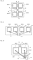
- FIG. 8 conceptually illustrates the condition (4). Note that arrows are provided for descriptive purposes in FIG. 8 and FIGS. 9 and 10 , which will be described hereinafter, and these arrows do not indicate components.
- the P terminal 31 is disposed on a center of the first circuit board 21 with a bonding material such as solder therebetween.
- the diodes SBD 1 -SBD 4 are disposed at four positions centered around the P terminal 31 and positioned at an equal distance from the P terminal 31 .
- a plurality of slits 41 - 46 having different widths are formed in the first circuit board 21 .
- the slits 41 and 44 are respectively formed between the diodes SBD 1 -SBD 4 and the P terminal 31 and are arranged such that slits denoted by a symbol with a lower value have a greater width.
- the slit 45 is formed between the diodes SBD 1 and SBD 3 .
- the slit 46 is formed between the diodes SBD 2 and SBD 4 .
- the widths of the slits 45 and 46 are less than that of the slit 42 and greater than that of the slit 43 .
- the wiring patterns forming paths in which diodes denoted by a symbol with a lower value among the diodes SBD 1 -SBD 4 are disposed have a smaller average cross-sectional area between the diode, i.e., a corresponding diode among the diodes SBD 1 -SBD 4 , and the P terminal 31 and have a larger parasitic inductance.
- the paths P 1 -P 4 are such that paths denoted by a symbol with a lower value have a larger parasitic inductance.
- FIG. 9 conceptually illustrates a combination of the conditions (3) and (4).
- the diodes SBD 1 , SBD 3 , SBD 4 , and SBD 2 are arranged in line in this order on the first circuit board 21 .
- the P terminal 31 is disposed in the vicinity of a center of the first circuit board 21 with a bonding material such as solder therebetween.
- the diodes SBD 1 and SBD 2 are at an equal distance from the P terminal 31 .
- the diodes SBD 3 and SBD 4 are at an equal distance from the P terminal 31 and positioned nearer to the P terminal 31 than the diodes SBD 1 and SBD 2 are.
- slits 51 - 54 that are equal in width are respectively formed at positions close to the diodes SBD 1 -SBD 4 .
- the wiring patterns on the first circuit board 21 are such that the wiring patterns forming the paths in which the diodes SBD 1 and SBD 3 are disposed have smaller average cross-sectional areas and larger parasitic inductances than the wiring patterns forming the paths in which the diodes SBD 2 and SBD 4 are disposed.
- the wiring pattern forming the path in which the diode SBD 1 is disposed has a smaller average cross-sectional area.
- the path P 1 in which the diode SBD 1 is disposed has a larger parasitic inductance than the path P 2 in which the diode SBD 2 is disposed.
- the distances between the diodes SBD 3 and SBD 4 and the P terminal 31 are shorter than the distances between the diodes SBD 1 and SBD 2 and the P terminal 31 .
- the wiring pattern forming the path in which the diode SBD 3 is disposed has a smaller average cross-sectional area.
- the parasitic inductance of the path P 3 in which the diode SBD 3 is disposed is smaller than those of the paths P 1 and P 2 but is larger than that of the path P 4 in which the diode SBD 4 is disposed.
- the paths P 1 -P 4 are such that paths denoted by a symbol with a lower value have a larger parasitic inductance.
- the paths depicted in FIG. 1 that extend from the U terminal 32 via the diodes SBD 1 -SBD 4 to the P terminal 31 correspond to the combination of the conditions (1) and (3).
- the paths depicted in FIG. 1 that extend from the N terminal 33 via the diodes SBD 5 -SBD 8 to the U terminal 32 correspond to the combination of the conditions (1) and (3).
- the bonding wires BW 1 -BW 4 are such that bonding wires denoted by a symbol with a lower value have a greater total length and a larger parasitic inductance.
- the diodes SBD 1 -SBD 4 are arranged such that diodes denoted by a symbol with a lower value (diodes to which a lower forward voltage is applied) are positioned farther from the P terminal 31 and have a longer wiring pattern formed on the first circuit board 21 and connected to the P terminal 31 .
- the wiring patterns forming the paths P 1 -P 4 that are provided on the first circuit board 21 are such that wiring patterns forming paths in which diodes denoted by a symbol with a lower value among the diodes SBD 1 -SBD 4 are disposed have a greater total length and a larger parasitic inductance.
- the paths P 1 -P 4 are such that paths denoted by a symbol with a lower value have a larger parasitic inductance.
- the bonding wires BW 5 -BW 8 are arranged such that bonding wires denoted by a symbol with a lower value have a greater total length and a larger parasitic inductance.
- the diodes SBD 5 -SBD 8 are arranged such that diodes denoted by a symbol with a lower value (diodes to which a lower forward voltage is applied) are positioned farther from the P terminal 31 and have a longer wiring pattern formed on the second circuit board 22 and connected to the U terminal 32 .
- the wiring patterns forming the paths P 5 -P 8 that are provided on the second circuit board 22 are such that wiring patterns forming paths in which diodes denoted by a symbol with a lower value among the diodes SBD 5 -SBD 8 are disposed have a greater total length and a larger parasitic inductance.
- the paths P 5 -P 8 are such that paths denoted by a symbol with a lower value have a larger parasitic inductance.
- the semiconductor module 1 does not need to be configured to satisfy all of the conditions (1)-(4).
- the wiring members W 1 A , W 2 A , W 1 B , and W 2 B may be formed to satisfy at least one of the conditions (2)-(4) such that the parasitic inductance of the entirety of the path P 1 is larger than the parasitic inductance of the entirety of the path P 2 .
- the conditions (1)-(4) have been presented as exemplary conditions.
- the semiconductor module 1 may be configured not to satisfy all of the conditions (1)-(4), as long as paths denoted by a symbol with a lower value have a larger parasitic inductance.
- a current from the U terminal 32 that is to arrive at the P terminal 31 starts to flow through the path in which the Schottky barrier diode that has the lowest forward voltage applied thereto among the paths P 1 -P 4 (i.e., path P 1 ) is disposed.
- path P 1 the path in which the Schottky barrier diode that has the lowest forward voltage applied thereto among the paths P 1 -P 4
- path P 1 a counter-electromotive force proportional to the parasitic inductance of the wiring members W 1 A and W 1 B (L 1 A +L 1 B ) is generated in the path P 1 .
- the counter-electromotive force disrupts the current flow through the path P 1 . In other words, the current easily flows through the paths P 2 -P 4 .
- the counter-electromotive force generated in the paths P 1 -P 4 decreases as the rate of change in the current flowing through the paths P 1 -P 4 becomes lower.
- the counter-electromotive force in the paths P 1 -P 4 becomes zero when the current flowing through the paths P 1 -P 4 is made constant. During the steady state, an equal current flows through the paths P 1 -P 4 .
- the wiring members for the paths may be formed, as described above, such that paths extending via Schottky barrier diodes that have a lower forward voltage applied thereto have a larger parasitic inductance, thereby causing a current flowing from the U terminal 32 to the P terminal 31 to be rapidly distributed between the paths P 1 -P 4 connected in parallel, with the result that the current is suppressed from being concentrated on a certain path (e.g., path P 1 ). Hence, abnormal heat generation or breakage of semiconductor elements such as the Schottky barrier diodes that could be caused by current concentration is prevented from occurring.
- the diodes SBD 5 -SBD 8 are arranged such that diodes denoted by a symbol with a lower value have a lower forward voltage applied thereto, and the paths P 5 -P 8 are arranged such that paths denoted by a symbol with a lower value have a larger parasitic inductance.
- a current is rapidly distributed between the paths P 5 -P 8 , thereby suppressing the current from being concentrated on a certain path.
- Suppressing abnormal heat generation of a certain semiconductor element that could be caused by current concentration allows a higher rated current to be set for the semiconductor module 1 .
- Such an effect of suppressing current concentration can be more prominent as the number of diodes connected in parallel increases.
- FIG. 10 conceptually illustrates relationships in length between bonding wires connecting a plurality of diodes connected in parallel to electrodes on a circuit board. For convenience sake, only a relationship between the paths P 1 and P 2 is described with reference to this example.
- the paths P 1 and P 2 satisfy only the condition (1) among the conditions (1)-(4). That is, the paths P 1 and P 2 in this example have the same configuration except that the total lengths of the bonding wires BW 1 and BW 2 are different. In other words, the parasitic inductances of the paths P 1 and P 2 are different because only of the difference in total length between the bonding wires BW 1 and BW 2 .
- X ⁇ Y (V: volt) be forward voltages based on the specification of the diodes SBD 1 and SBD 2
- X ⁇ Y (V) and X+Y (V) be the measured values.
- a current of ⁇ amperes (A) flows through the paths P 1 and P 2 for ⁇ , nanoseconds (ns).
- Substituting the exemplified values into the formula (1) provides the following formula (2).
- the formula (3) below is obtained from the following formula (2).
- parasitic inductance (L 2 A +L 2 B ) is 12 nH.
- the total length of the bonding wire BW 2 is made less than that of the bonding wire BW 1 by 10%.
- parasitic inductance (L 1 A +L 1 B ) is larger than parasitic inductance (L 2 A +L 2 B ) by 0.12 nH.
- the numbers or positions of switching elements and diodes to be disposed on the layered substrate 2 in the embodiments described above are not limited to the abovementioned configurations and can be changed, as appropriate.
- the number or layout of circuit boards to be disposed on the layered substrate 20 in the embodiments described above is not limited to the abovementioned configurations and can be changed, as appropriate.
- parasitic inductances are defined for all of the paths connected in parallel (in particular, the parasitic inductances of the paths P 1 -P 4 (or P 5 -P 8 ) go from larger to smaller in this order).
- simply defining parasitic inductances for at least two paths e.g., making the parasitic inductance of the path P 1 larger than that of the path P 2 ) provides the effect of suppressing current concentration on a certain path.
- the parasitic inductance of a certain path of a diode is expressed by the sum of the inductance on the anode-electrode side (e.g., L 1 A ) and the inductance on the cathode-electrode side (e.g., L 1 B ).
- the anode-electrode-side inductance of a diode to which a low forward voltage is applied is preferably larger than the anode-electrode-side inductance of a diode to which a high forward voltage is applied.
- the magnitudes of the inductances of certain paths of diodes connected in parallel may be adjusted in accordance with the inductances on the anode-electrode sides.
- the paths P 1 -P 4 may be arranged such that the inductances L 1 B -L 4 B of the wiring members W 1 B -W 4 B electrically connected to the cathode electrodes become equal and the inductances L 1 A -L 4 A of the wiring members W 1 A -W 4 A electrically connected to the anode electrodes are such that inductances denoted by a symbol with a lower value become larger.
- the anode electrodes are present on the surface side of the semiconductor module 1 and the inductances can be easily adjusted by changing the wiring lengths or the like of the bonding wires BW 1 -BW 4 .
- the inductances of the diodes may be adjusted not only by adjusting the wiring members on the anode-electrode side but also by adjusting the wiring members on the cathode-electrode side.
- the switching elements MOS 1 -MOS 4 also have a problem of current concentration on a certain switching element, as with the diodes SBD 1 -SBD 4 .
- a current is typically concentrated more on switching elements to which a lower ON voltage (V ON ) is applied.
- the switching element to which the lowest ON voltage is applied is disposed as the switching element MOS 1
- the other switching elements are disposed as the switching elements MOS 2 -MOS 4 in ascending order of ON voltage.
- the switching elements MOS 1 -MOS 4 are arranged such that switching elements denoted by a symbol with a lower value have a lower ON voltage applied thereto.
- wiring members for paths P 1 ′-P 4 ′ from the P terminal 31 via the switching elements MOS 1 -MOS 4 to the U terminal 32 are formed such that paths extending via switching elements denoted by a symbol with a lower value have a larger parasitic inductance.
- a current is rapidly distributed between the paths P 1 ′-P 4 ′, thereby suppressing the current from being concentrated on a certain path.
- the switching elements MOS 5 -MOS 8 may be arranged such that switching elements denoted by a symbol with a lower value have a lower ON voltage applied thereto.
- paths P 5 ′-P 8 ′ from the U terminal 32 via the switching elements MOS 5 -MOS 8 to the N terminal 33 may be configured such that paths extending via switching elements denoted by a symbol with a lower value have a larger parasitic inductance.
- a current is rapidly distributed between the paths P 5 ′-P 8 ′, thereby suppressing the current from being concentrated on a certain path.
- the semiconductor module 1 may be provided with an electronic circuit that includes a plurality of switching elements connected in parallel and including a first switching element (e.g., switching element MOS 1 ) and a second switching element (e.g., switching element MOS 2 ) that has applied thereto a higher ON voltage than the first switching element, wherein an inductance of a first path from a first terminal (e.g., P terminal 31 ) via the first switching element to a second terminal (e.g., U terminal 32 ) is larger than an inductance of a second path from the first terminal via the second switching element to the second terminal.
- a first switching element e.g., switching element MOS 1
- a second switching element e.g., switching element MOS 2
- the wiring members are formed such that paths denoted by a symbol with a lower value among the paths P 1 -P 4 have a larger parasitic inductance.
- inductance elements each having a different inductance e.g., inductors with cores each having a different magnetic permeability
- FIG. 11 schematically illustrates a semiconductor apparatus 100 in accordance with an embodiment of the invention.
- the semiconductor apparatus 100 includes semiconductor modules 1 A and 1 B connected in parallel.
- the semiconductor modules 1 A and 1 B have a similar configuration to the semiconductor module 1 in accordance with the embodiments described above.
- FIG. 11 depicts the semiconductor module 1 A using a block having a P terminal 31 A and an N terminal 33 A and depicts the semiconductor module 1 B using a block having a P terminal 31 B and an N terminal 33 B.
- the P terminals 31 A and 31 B are electrically connected to a positive potential point 200 A on a positive-electrode side of a power supply 200 (one of a pair of terminals).
- the N terminals 33 A and 33 B are electrically connected to a negative potential point 200 B on a negative-electrode side of the power supply 200 (another of the pair of terminals).
- Let symbol P 1 A denote a path from the positive potential point 200 A via the semiconductor module 1 A to the negative potential point 200 B, and let symbol P 1 B denote a path from the positive potential point 200 A via the semiconductor module 1 B to the negative potential point 200 B.
- the forward voltage on the semiconductor module 1 A is lower than that on the semiconductor module 1 B, and the parasitic inductance of the path P 1 A is larger than that of the path P 1 B .
- the current starts to flow through the path P 1 A having disposed therein the semiconductor module 1 A to which a low forward voltage is applied.
- a change (increase) in the current flowing through the path P 1 A a counter-electromotive force proportional to the parasitic inductance of the wiring member of the path P 1 A is generated in the path P 1 A .
- the counter-electromotive force disrupts the current flow through the path P 1 A .
- the current easily flows through the path P 1 B .
- the current is rapidly distributed between the paths P 1 A and P 1 B connected in parallel, thereby suppressing current concentration on the path P 1 A .
- abnormal heat generation or breakage of semiconductor elements such as Schottky barrier diodes that could be caused by current concentration is prevented from occurring.
- FIG. 11 depicts a semiconductor apparatus having two semiconductor modules connected in parallel
- a semiconductor apparatus having three or more semiconductor modules connected in parallel also falls within the scope of the invention.
- Embodiments are not limited to the above-described embodiments or variations, and various changes, replacements, or modifications may be made without departing from the gist of the technical idea.
- the invention may be implemented using such a method. Accordingly, the claims cover all aspects that can be included in the scope of the technical idea.
- the electronic circuit indicated with reference to the above-described embodiments includes a plurality of diodes connected in parallel and including a first diode and a second diode that has applied thereto a higher forward voltage than the first diode, wherein an inductance of a first path from a first terminal via the first diode to a second terminal is larger than an inductance of a second path from the first terminal via the second diode to the second terminal.
- the electronic circuit indicated with reference to the above-described embodiments is such that paths extending from the first terminal to the second terminal via the plurality of diodes are arranged such that paths extending via diodes that have a lower forward voltage applied thereto have a larger inductance.
- the electronic circuit indicated with reference to the above-described embodiments is such that the inductances are inductances on anode sides.
- the semiconductor module indicated with reference to the above-described embodiments is provided with an electronic circuit that includes a plurality of diodes connected in parallel and including a first diode and a second diode that has applied thereto a higher forward voltage than the first diode, wherein an inductance of a wiring member forming a first path from a first terminal via the first diode to a second terminal is larger than an inductance of a wiring member forming a second path from the first terminal via the second diode to the second terminal.
- the semiconductor module indicated with reference to the above-described embodiments includes a substrate mounted with the electronic circuit, wherein the wiring member for the first path includes a first conductive wire disposed on the substrate and connecting the first or second terminal to the first diode, the wiring member for the second path includes a second conductive wire disposed on the substrate and connecting the first or second terminal to the second diode, and an inductance of the first conductive wire is larger than an inductance of the second conductive wire.
- the semiconductor module indicated with reference to the above-described embodiments satisfies at least one of the following conditions (1) and (2):
- the first conductive wire has a greater total length than the second conductive wire
- the first conductive wire has a smaller cross-sectional area than the second conductive wire.
- the semiconductor module indicated with reference to the above-described embodiments includes a substrate mounted with the electronic circuit, wherein the wiring member for the first path includes a first wiring pattern disposed on the substrate and connecting the first or second terminal to the first diode, the wiring member for the second path includes a second wiring pattern disposed on the substrate and connecting the first or second terminal to the second diode, and an inductance of the first wiring pattern is larger than an inductance of the second wiring pattern.
- the semiconductor module indicated with reference to the above-described embodiments satisfies at least one of the following conditions (3) and (4):
- the first wiring pattern has a greater total length than the second wiring pattern
- the first wiring pattern has a smaller cross-sectional area than the second wiring pattern.
- the semiconductor module indicated with reference to the above-described embodiments is such that the plurality of diodes have a same structure.
- the semiconductor module indicated with reference to the above-described embodiments is such that the plurality of diodes are produced using silicon carbide (SiC).
- the semiconductor module indicated with reference to the above-described embodiments includes a plurality of said semiconductor modules, the plurality of semiconductor modules being connected in parallel between a pair of terminals, wherein paths each extending from one to another of the pair of terminals via each of the plurality of semiconductor modules are such that paths extending via semiconductor modules that have a lower forward voltage applied thereto have a larger inductance.
- the electronic circuit indicated with reference to the above-described embodiments is provided with a plurality of switching elements connected in parallel and including a first switching element and a second switching element that has applied thereto a higher ON voltage than the first switching element, wherein an inductance of a first path from a first terminal via the first switching element to a second terminal is larger than an inductance of a second path from the first terminal via the second switching element to the second terminal.
- the present invention has the effect of suppressing a current from being concentrated on a certain semiconductor element among a plurality of semiconductor elements connected in parallel and can be useful especially for electronic circuits, semiconductor modules, and semiconductor apparatuses.
Landscapes
- Engineering & Computer Science (AREA)
- Power Engineering (AREA)
- Physics & Mathematics (AREA)
- Condensed Matter Physics & Semiconductors (AREA)
- General Physics & Mathematics (AREA)
- Computer Hardware Design (AREA)
- Microelectronics & Electronic Packaging (AREA)
- Inverter Devices (AREA)
- Wire Bonding (AREA)
- Geometry (AREA)
- Electronic Switches (AREA)
- Power Conversion In General (AREA)
Abstract
Description
- Patent Document 1: Japanese Laid-open Patent Publication No. 2004-31590
(2) The first conductive wire has a smaller cross-sectional area than the second conductive wire.
(3) The total length of a wiring pattern forming one path (hereinafter, “first wiring pattern”) is greater than that of a wiring pattern forming another path in which a Schottky barrier diode is disposed and to which a forward voltage higher than that applied to the one path is applied (hereinafter, “second wiring pattern”).
(4) The first wiring pattern has a smaller cross-sectional area than the second wiring pattern.
VF 1+(L1A +L1B)dI 1 /dt=VF 2+(L2A +L2B)dI 2 /dt (1)
−2Y(V)={(L2A +L2B)−(L1A +L1B)}×α(A)/β(ns) (2)
(L1A +L1B)−(L2A +L2B)=2Yβ/α(nanohenry: nH) (3)
- 1: Semiconductor module
- 2: Layered substrate
- 10: Base board
- 12: Case member
- 13, 14: Terminal member
- 20: Insulation layer
- 21: First circuit board
- 22: Second circuit board
- 23: Third circuit board
- 31: P terminal (Positive potential point)
- 32: U terminal (Intermediate potential point)
- 33: N terminal (Negative potential point)
- BD1-BD8: Diode
- BW1-BW8: Bonding wire
- L1 A-L8 A, L1 B-L8 B: Inductance
- MOS1-M0S8: Switching element
- P1-P8: Path
- SBD1-SBD8: Diode
- T1-T8: Electrode
- W1 A-W8 A, W1 B-W8 B: Wiring member
Claims (11)
Applications Claiming Priority (3)
| Application Number | Priority Date | Filing Date | Title |
|---|---|---|---|
| JP2019232117A JP7447480B2 (en) | 2019-12-23 | 2019-12-23 | Electronic circuits, semiconductor modules and semiconductor devices |
| JP2019-232117 | 2019-12-23 | ||
| JPJP2019-232117 | 2019-12-23 |
Publications (2)
| Publication Number | Publication Date |
|---|---|
| US20210193651A1 US20210193651A1 (en) | 2021-06-24 |
| US11631668B2 true US11631668B2 (en) | 2023-04-18 |
Family
ID=76206017
Family Applications (1)
| Application Number | Title | Priority Date | Filing Date |
|---|---|---|---|
| US17/085,696 Active 2041-07-30 US11631668B2 (en) | 2019-12-23 | 2020-10-30 | Current concentration-suppressed electronic circuit, and semiconductor module and semiconductor apparatus containing the same |
Country Status (4)
| Country | Link |
|---|---|
| US (1) | US11631668B2 (en) |
| JP (2) | JP7447480B2 (en) |
| CN (1) | CN113035818A (en) |
| DE (1) | DE102020128768A1 (en) |
Families Citing this family (2)
| Publication number | Priority date | Publication date | Assignee | Title |
|---|---|---|---|---|
| JP7447480B2 (en) * | 2019-12-23 | 2024-03-12 | 富士電機株式会社 | Electronic circuits, semiconductor modules and semiconductor devices |
| EP4160677A1 (en) * | 2021-09-30 | 2023-04-05 | Siemens Aktiengesellschaft | Semiconductor assembly comprising at least two semiconductor elements |
Citations (9)
| Publication number | Priority date | Publication date | Assignee | Title |
|---|---|---|---|---|
| JP2004031590A (en) | 2002-06-25 | 2004-01-29 | Hitachi Unisia Automotive Ltd | Semiconductor device |
| US20080043500A1 (en) * | 2004-07-01 | 2008-02-21 | Katsunori Asano | Snubber Circuit and Power Semiconductor Device Having Snubber Circuit |
| US20090168471A1 (en) * | 2007-12-26 | 2009-07-02 | Dai Tsugawa | Circuit device having a free wheeling diode, circuit device and power converter using diodes |
| US20090206812A1 (en) * | 2008-02-15 | 2009-08-20 | Denso Corporation | Power switching circuit improved to reduce loss due to reverse recovery current |
| US20100039843A1 (en) * | 2007-02-02 | 2010-02-18 | Fuji Electric Systems Co., Ltd | Semiconductor module for use in power supply |
| US20130082284A1 (en) | 2010-05-27 | 2013-04-04 | Rohm Co., Ltd. | Electronic circuit |
| US20150229205A1 (en) * | 2014-02-13 | 2015-08-13 | Nxp B.V. | Diode circuit and power factor correction boost converter using the same |
| US20170207213A1 (en) * | 2016-01-19 | 2017-07-20 | Mitsubishi Electric Corporation | Power Module with MOSFET Body Diode on which Energization Test can be Conducted Efficiently |
| US20180034362A1 (en) * | 2016-07-29 | 2018-02-01 | Fuji Electric Co., Ltd. | Three-level chopper apparatus |
Family Cites Families (14)
| Publication number | Priority date | Publication date | Assignee | Title |
|---|---|---|---|---|
| JPH052452U (en) * | 1991-02-21 | 1993-01-14 | 三菱電機株式会社 | Semiconductor circuit breaker |
| JP3222341B2 (en) * | 1995-01-11 | 2001-10-29 | 株式会社日立製作所 | Semiconductor module |
| JP3508670B2 (en) * | 1999-02-05 | 2004-03-22 | 株式会社豊田自動織機 | Semiconductor module |
| JP4484400B2 (en) * | 2000-08-28 | 2010-06-16 | 三菱電機株式会社 | Semiconductor device |
| JP2003060157A (en) * | 2001-08-08 | 2003-02-28 | Mitsubishi Electric Corp | Power module |
| JP2008011280A (en) * | 2006-06-29 | 2008-01-17 | Sanyo Electric Co Ltd | Switch circuit device |
| JP2011216522A (en) * | 2010-03-31 | 2011-10-27 | Renesas Electronics Corp | Semiconductor device |
| JP5939055B2 (en) * | 2012-06-28 | 2016-06-22 | 住友電気工業株式会社 | Semiconductor device and manufacturing method of semiconductor device |
| JP5710555B2 (en) * | 2012-07-31 | 2015-04-30 | 株式会社東芝 | Semiconductor device |
| WO2014069525A1 (en) * | 2012-10-31 | 2014-05-08 | ローム株式会社 | Electronic circuit |
| JP6041770B2 (en) * | 2013-08-26 | 2016-12-14 | カルソニックカンセイ株式会社 | Semiconductor device |
| DE102014111931B4 (en) * | 2014-08-20 | 2021-07-08 | Infineon Technologies Ag | Low-inductance circuit arrangement with load current busbar |
| JP6672908B2 (en) * | 2016-03-10 | 2020-03-25 | 富士電機株式会社 | Semiconductor device and method of manufacturing semiconductor device |
| JP7447480B2 (en) * | 2019-12-23 | 2024-03-12 | 富士電機株式会社 | Electronic circuits, semiconductor modules and semiconductor devices |
-
2019
- 2019-12-23 JP JP2019232117A patent/JP7447480B2/en active Active
-
2020
- 2020-10-30 US US17/085,696 patent/US11631668B2/en active Active
- 2020-11-02 CN CN202011204553.0A patent/CN113035818A/en active Pending
- 2020-11-02 DE DE102020128768.2A patent/DE102020128768A1/en active Pending
-
2023
- 2023-11-01 JP JP2023187666A patent/JP2024008998A/en active Pending
Patent Citations (9)
| Publication number | Priority date | Publication date | Assignee | Title |
|---|---|---|---|---|
| JP2004031590A (en) | 2002-06-25 | 2004-01-29 | Hitachi Unisia Automotive Ltd | Semiconductor device |
| US20080043500A1 (en) * | 2004-07-01 | 2008-02-21 | Katsunori Asano | Snubber Circuit and Power Semiconductor Device Having Snubber Circuit |
| US20100039843A1 (en) * | 2007-02-02 | 2010-02-18 | Fuji Electric Systems Co., Ltd | Semiconductor module for use in power supply |
| US20090168471A1 (en) * | 2007-12-26 | 2009-07-02 | Dai Tsugawa | Circuit device having a free wheeling diode, circuit device and power converter using diodes |
| US20090206812A1 (en) * | 2008-02-15 | 2009-08-20 | Denso Corporation | Power switching circuit improved to reduce loss due to reverse recovery current |
| US20130082284A1 (en) | 2010-05-27 | 2013-04-04 | Rohm Co., Ltd. | Electronic circuit |
| US20150229205A1 (en) * | 2014-02-13 | 2015-08-13 | Nxp B.V. | Diode circuit and power factor correction boost converter using the same |
| US20170207213A1 (en) * | 2016-01-19 | 2017-07-20 | Mitsubishi Electric Corporation | Power Module with MOSFET Body Diode on which Energization Test can be Conducted Efficiently |
| US20180034362A1 (en) * | 2016-07-29 | 2018-02-01 | Fuji Electric Co., Ltd. | Three-level chopper apparatus |
Also Published As
| Publication number | Publication date |
|---|---|
| JP7447480B2 (en) | 2024-03-12 |
| JP2024008998A (en) | 2024-01-19 |
| DE102020128768A1 (en) | 2021-06-24 |
| US20210193651A1 (en) | 2021-06-24 |
| CN113035818A (en) | 2021-06-25 |
| JP2021100082A (en) | 2021-07-01 |
Similar Documents
| Publication | Publication Date | Title |
|---|---|---|
| US11605613B2 (en) | Semiconductor device | |
| US11398450B2 (en) | Semiconductor module | |
| US20210280555A1 (en) | Semiconductor module | |
| US11923266B2 (en) | Semiconductor module circuit structure | |
| US12500210B2 (en) | Module | |
| US20210280549A1 (en) | Semiconductor module | |
| US11705438B2 (en) | Semiconductor device | |
| JP2017162866A (en) | Semiconductor device | |
| JP2024008998A (en) | Electronic circuits, semiconductor modules and semiconductor devices | |
| CN112054019B (en) | Semiconductor devices | |
| JP7438021B2 (en) | semiconductor equipment | |
| US20210366813A1 (en) | Power semiconductor module | |
| US11133303B2 (en) | Semiconductor device and semiconductor arrangement comprising semiconductor devices | |
| US12355015B2 (en) | Semiconductor device | |
| US12334427B2 (en) | Semiconductor device | |
| CN114788158A (en) | Electronic circuit and semiconductor module | |
| KR102434465B1 (en) | Flip-stack type semiconductor package and method thereof | |
| US20250149528A1 (en) | Semiconductor device | |
| US20240088796A1 (en) | Semiconductor module |
Legal Events
| Date | Code | Title | Description |
|---|---|---|---|
| AS | Assignment |
Owner name: FUJI ELECTRIC CO., LTD., JAPAN Free format text: ASSIGNMENT OF ASSIGNORS INTEREST;ASSIGNOR:OKUMURA, KEIJI;REEL/FRAME:054227/0571 Effective date: 20201012 |
|
| FEPP | Fee payment procedure |
Free format text: ENTITY STATUS SET TO UNDISCOUNTED (ORIGINAL EVENT CODE: BIG.); ENTITY STATUS OF PATENT OWNER: LARGE ENTITY |
|
| STPP | Information on status: patent application and granting procedure in general |
Free format text: APPLICATION DISPATCHED FROM PREEXAM, NOT YET DOCKETED |
|
| STPP | Information on status: patent application and granting procedure in general |
Free format text: DOCKETED NEW CASE - READY FOR EXAMINATION |
|
| STPP | Information on status: patent application and granting procedure in general |
Free format text: NON FINAL ACTION MAILED |
|
| STPP | Information on status: patent application and granting procedure in general |
Free format text: RESPONSE TO NON-FINAL OFFICE ACTION ENTERED AND FORWARDED TO EXAMINER |
|
| STCF | Information on status: patent grant |
Free format text: PATENTED CASE |