US11631514B2 - Superconducting magnet with improved thermal and electrical stabilities and method for manufacturing the same - Google Patents
Superconducting magnet with improved thermal and electrical stabilities and method for manufacturing the same Download PDFInfo
- Publication number
- US11631514B2 US11631514B2 US16/229,157 US201816229157A US11631514B2 US 11631514 B2 US11631514 B2 US 11631514B2 US 201816229157 A US201816229157 A US 201816229157A US 11631514 B2 US11631514 B2 US 11631514B2
- Authority
- US
- United States
- Prior art keywords
- epoxy
- superconducting magnet
- superconducting
- carbon nanotubes
- carbon nanotube
- Prior art date
- Legal status (The legal status is an assumption and is not a legal conclusion. Google has not performed a legal analysis and makes no representation as to the accuracy of the status listed.)
- Active, expires
Links
Images


Classifications
-
- H—ELECTRICITY
- H01—ELECTRIC ELEMENTS
- H01F—MAGNETS; INDUCTANCES; TRANSFORMERS; SELECTION OF MATERIALS FOR THEIR MAGNETIC PROPERTIES
- H01F6/00—Superconducting magnets; Superconducting coils
- H01F6/02—Quenching; Protection arrangements during quenching
-
- C—CHEMISTRY; METALLURGY
- C01—INORGANIC CHEMISTRY
- C01B—NON-METALLIC ELEMENTS; COMPOUNDS THEREOF; METALLOIDS OR COMPOUNDS THEREOF NOT COVERED BY SUBCLASS C01C
- C01B32/00—Carbon; Compounds thereof
- C01B32/15—Nano-sized carbon materials
- C01B32/158—Carbon nanotubes
- C01B32/168—After-treatment
-
- H—ELECTRICITY
- H01—ELECTRIC ELEMENTS
- H01F—MAGNETS; INDUCTANCES; TRANSFORMERS; SELECTION OF MATERIALS FOR THEIR MAGNETIC PROPERTIES
- H01F41/00—Apparatus or processes specially adapted for manufacturing or assembling magnets, inductances or transformers; Apparatus or processes specially adapted for manufacturing materials characterised by their magnetic properties
- H01F41/02—Apparatus or processes specially adapted for manufacturing or assembling magnets, inductances or transformers; Apparatus or processes specially adapted for manufacturing materials characterised by their magnetic properties for manufacturing cores, coils, or magnets
- H01F41/04—Apparatus or processes specially adapted for manufacturing or assembling magnets, inductances or transformers; Apparatus or processes specially adapted for manufacturing materials characterised by their magnetic properties for manufacturing cores, coils, or magnets for manufacturing coils
- H01F41/048—Superconductive coils
-
- H—ELECTRICITY
- H01—ELECTRIC ELEMENTS
- H01F—MAGNETS; INDUCTANCES; TRANSFORMERS; SELECTION OF MATERIALS FOR THEIR MAGNETIC PROPERTIES
- H01F41/00—Apparatus or processes specially adapted for manufacturing or assembling magnets, inductances or transformers; Apparatus or processes specially adapted for manufacturing materials characterised by their magnetic properties
- H01F41/02—Apparatus or processes specially adapted for manufacturing or assembling magnets, inductances or transformers; Apparatus or processes specially adapted for manufacturing materials characterised by their magnetic properties for manufacturing cores, coils, or magnets
- H01F41/04—Apparatus or processes specially adapted for manufacturing or assembling magnets, inductances or transformers; Apparatus or processes specially adapted for manufacturing materials characterised by their magnetic properties for manufacturing cores, coils, or magnets for manufacturing coils
- H01F41/12—Insulating of windings
- H01F41/127—Encapsulating or impregnating
-
- H—ELECTRICITY
- H01—ELECTRIC ELEMENTS
- H01F—MAGNETS; INDUCTANCES; TRANSFORMERS; SELECTION OF MATERIALS FOR THEIR MAGNETIC PROPERTIES
- H01F6/00—Superconducting magnets; Superconducting coils
- H01F6/06—Coils, e.g. winding, insulating, terminating or casing arrangements therefor
-
- C—CHEMISTRY; METALLURGY
- C08—ORGANIC MACROMOLECULAR COMPOUNDS; THEIR PREPARATION OR CHEMICAL WORKING-UP; COMPOSITIONS BASED THEREON
- C08K—Use of inorganic or non-macromolecular organic substances as compounding ingredients
- C08K3/00—Use of inorganic substances as compounding ingredients
- C08K3/02—Elements
- C08K3/04—Carbon
- C08K3/041—Carbon nanotubes
Definitions
- Embodiments of the inventive concepts described herein relate to a superconducting magnet and a method for manufacturing the same, and more particularly, relate to a superconducting magnet with improved thermal and electrical stabilities by inserting a filler in an impregnating material of the superconducting magnet used at a very low temperature and a method for manufacturing the same.
- a superconducting magnet As research on high magnetic field develops, a superconducting magnet has been applied not only in medical field but also in electric power and energy field.
- the magnet In case of a low-temperature superconducting magnet, or a magnet used for rotation of a motor or a generator, etc., the magnet is impregnated with an epoxy for a very low temperature. Impregnating the superconducting magnet with the epoxy relaxes the Lorentz force of the magnet. Further, impregnating the superconducting magnet with the epoxy allows the magnet to withstand mechanical vibration that occurs when applied to a machine such as a motor or a generator.
- FIG. 1 is a diagram schematically illustrating heat generation in a typical superconducting magnet due to a quench.
- Existing superconducting magnet has an epoxy surrounding a superconducting winding such that the superconducting winding is impregnated in the epoxy.
- the heat When local heat is generated in a specific region due to an unspecified cause, the heat must be properly diffused, and cooled immediately.
- Embodiments of the inventive concepts provide a superconducting magnet that is able to solve a problem that, when local heat is generated at the superconducting magnet impregnated with a conventional epoxy, the heat may not be efficiently diffused due to a low thermal conductivity of the epoxy material.
- Embodiments of the inventive concepts provide a superconducting magnet that reduces a difference in a thermal shrinkage between a superconducting winding and the epoxy surrounding the winding in an impregnating manner.
- a mechanical internal stress may occur due to the difference in the thermal shrinkage when the superconducting magnet is cooled.
- a superconducting magnet includes a bobbin defining a central portion of the superconducting magnet, a superconducting winding wound around an outer face of the bobbin, and an epoxy surrounding the superconducting winding such that the superconducting winding is impregnated in the epoxy, wherein the epoxy contains carbon nanotubes.
- the carbon nanotubes are subjected to surface treatment such that the carbon nanotubes are dispersed in the epoxy.
- the surface-treatment of the carbon nanotubes includes heat-treating the carbon nanotubes in a solution containing sulfuric acid and nitric acid to form a COOH functional group on surfaces of the carbon nanotubes.
- a content of the carbon nanotubes is in a range of 0.1 to 5 wt % based on a total weight of the epoxy.
- a method for manufacturing a superconducting magnet includes providing a bobbin defining a central portion of the superconducting magnet, winding a superconducting wire around an outer face of the bobbin to form a superconducting winding, and impregnating the superconducting winding with an epoxy such that the epoxy surrounds the superconducting winding, wherein the epoxy contains carbon nanotubes.
- the carbon nanotubes are subjected to surface treatment such that the carbon nanotubes are dispersed in the epoxy at an increased dispersity.
- the surface-treatment of the carbon nanotubes includes heat-treating the carbon nanotubes in a solution containing sulfuric acid and nitric acid to form a functional group on surfaces of the carbon nanotubes.
- a content of the carbon nanotubes is in a range of 0.1 to 5 wt % based on a total weight of the epoxy.
- inclusion of the carbon nanotubes in the epoxy improves thermal and electrical stabilities of the superconducting magnet, and reduces a difference in thermal shrinkage between the superconducting winding and the epoxy to prevent degradation of superconductive property of the magnet.
- the thermal conductivity of the epoxy is improved by impregnating the superconducting magnet with the epoxy containing the surface-treated carbon nanotube.
- the heat is efficiently diffused, thereby improving the thermal and electrical stabilities of the superconducting magnet.
- the superconducting magnet with improved thermal and electrical stabilities and the method for manufacturing the same according to the inventive concept may prevent degradation of superconductive property by reducing the difference in the thermal shrinkage between the superconducting winding and the epoxy that occurs during cooling.
- FIG. 1 is a diagram schematically illustrating heat generation in a typical superconducting magnet due to a quench
- FIG. 2 is a cross-sectional view of a superconducting magnet according to an embodiment of the inventive concept
- FIG. 3 is SEM images of an epoxy with a non-surface-treated carbon nanotube, and with a surface-treated carbon nanotube,
- FIG. 4 A and FIG. 4 B are graphs showing the time to reach a very low temperature (77 K) from a room temperature when a carbon nanotube is added in an epoxy which is a component of a superconducting magnet,
- FIG. 5 A and FIG. 5 B are graphs showing a quench test of a superconducting magnet containing a carbon nanotube in an epoxy
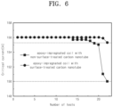
- FIG. 6 shows critical current values obtained by repeating 22 times a process of cooling a superconducting magnet containing a carbon nanotube at room temperature, measuring the critical currents, and then heating it to the room temperature again.
- the inventive concept relates to a superconducting magnet with improved thermal and electrical stabilities, and a manufacturing method of the same.
- the superconducting magnet includes: a bobbin defining a central portion of the superconducting magnet; a superconducting winding wound around an outer face of the bobbin; and an epoxy surrounding the superconducting winding such that the superconducting winding is impregnated in the epoxy, wherein the epoxy contains carbon nanotubes.
- FIG. 2 is a cross-sectional view of a superconducting magnet according to an embodiment of the inventive concept.
- a superconducting magnet 100 may include a bobbin 110 , a superconducting winding 120 , and an epoxy impregnation 130 .
- the bobbin 110 defines the central portion of the superconducting magnet 100 .
- a bakelite material having a low thermal conductivity may be used as the bobbin.
- the superconducting winding 120 may be formed along the outer face of the bobbin 110 .
- the superconducting winding 120 may be wound around the bobbin several times.
- the superconducting winding 120 may include both a low temperature superconductor having superconductivity at a temperature less than 30K, and a high temperature superconductor having superconductivity at a temperature of 30K or more. In the superconducting winding 120 , a current may flow without a resistance at a temperature lower than or equal to a critical temperature of the superconducting material.
- the superconducting winding 120 is surrounded with the epoxy 130 such that the superconducting winding 120 is impregnated in the epoxy 130 .
- a surface-treated carbon nanotube may be added to the epoxy.
- the superconducting magnet When local heat is generated in the superconducting winding 120 included in the superconducting magnet, the superconducting magnet needs to increase stabilities of the superconducting magnet by efficiently diffusing the heat. Otherwise, the superconducting winding 120 may lose superconductivity, and resistance may increase due to the heat.
- the superconducting winding 120 was surrounded with the epoxy such that the superconducting winding is impregnated in the epoxy. Further, a carbon nanotube with a high thermal conductivity was added to the epoxy. When the carbon nanotube is added to increase a thermal conductivity of the epoxy, the heat may be efficiently diffused, thereby improving thermal and electrical stabilities of the superconducting magnet 100 .
- the difference in the thermal shrinkage between the superconducting winding 120 and the epoxy 130 for a very low temperature may generate a mechanical internal stress in the superconducting magnet 100 when the superconducting magnet is cooled.
- the mechanical internal stress may cause degradation of superconductive property of the superconducting magnet 100 .
- the difference in the thermal shrinkage between the superconducting winding 120 and the epoxy 130 may be reduced.
- a surface-treated carbon nanotube may be used as the carbon nanotube contained in the epoxy to increase dispersivity within the epoxy.
- FIG. 3 is SEM images of an epoxy with a non-surface-treated carbon nanotube, and with a surface-treated carbon nanotube.
- the carbon nanotubes are surface-treated, the carbon nanotubes are formed to uniformly dispersed in the epoxy.
- Sulfuric acid and nitric acid may be used for the surface-treatment of the carbon nanotube.
- a surface-treated carbon nanotube 190 may be obtained through a heat treatment of the sulfuric acid and the nitric acid at a mass ratio of 3:1 at about 100° C. for about 30 minutes.
- the sulfuric acid and the nitric acid are filtered through a membrane to obtain the surface-treated carbon nanotube 190 .
- COOH functional group is formed to the carbon nanotube, thereby improving dispersity among the carbon nanotubes in the epoxy.
- the functional group is formed on a surface of the carbon nanotube through the surface-treatment, thus the dispersity of the carbon nanotubes in the epoxy 130 may be improved (See FIG. 3 B ).
- the carbon nanotube is contained in the epoxy, and a content of the carbon nanotube contained in the epoxy is preferably 0.1 to 5 wt % based on a total weight of the epoxy.
- a thermal conductivity of the epoxy is increased, so that when local heat is generated, the heat may be efficiently diffused.
- FIG. 4 A and FIG. 4 B are graphs showing the time to reach a very low temperature (77 K) from a room temperature when a carbon nanotube is added in an epoxy which is a component of a superconducting magnet.
- thermocouples 160 at an innermost epoxy (TC1), a middle epoxy (TC2), and an outermost epoxy (TC3) were measured (See positions of the thermocouples 160 in FIG. 2 ).
- FIG. 4 A and FIG. 4 B show the time at which the superconducting magnet containing the carbon nanotube in the epoxy reaches a very low temperature (77 K) from the room temperature.
- FIG. 4 A shows the time to reach a very low temperature (77 K) from the room temperature when the non-surface-treated carbon nanotube is added.
- FIG. 4 B shows the time to reach a very low temperature (77 K) from the room temperature when the surface-treated carbon nanotube is added. Experiments of reaching the very low temperature (77K) may be carried out by placing in liquid nitrogen.
- the time to reach the very low temperature (77K) of all the innermost epoxy (TC1), the middle epoxy (TC2), and the outermost epoxy (TC3) is 58.2 seconds.
- the time to reach the very low temperature (77K) of all the innermost epoxy (TC1), the middle epoxy (TC2), and the outermost epoxy (TC3) is 39.8 seconds.
- the time to reach the very low temperature (77K) of all the innermost epoxy (TC1), the middle epoxy (TC2), and the outermost epoxy (TC3) is 468.1 seconds.
- the time to reach the very low temperature (77K) of the superconducting magnet when the non-surface-treated carbon nanotube was added was 58.2 seconds, which has improved 7.0 times higher than that of 468.1 seconds when only the existing epoxy was added. Further, it may be confirmed that the time to reach the very low temperature (77K) of the superconducting magnet when the surface-treated carbon nanotube was added was 39.8 seconds, which has improved 11.8 times higher than that of 468.1 seconds when only the existing epoxy was added.
- the superconducting magnet is cooled more quickly than when only the existing epoxy is added.
- FIG. 5 A and FIG. 5 B are graphs showing a quench test of a superconducting magnet containing a carbon nanotube in an epoxy.
- FIG. 5 A shows a quench test when a non-surface-treated carbon nanotube 180 is added
- FIG. 5 B shows a quench test when a surface-treated carbon nanotube is added.
- the quench test may evaluate the thermal and electrical stabilities of the superconducting magnet 100 by applying an operating current of 93.6 A, and applying heat energy through a heater to confirm a minimum quench energy (MQE) that the quench is generated. It may be evaluated that the larger the MQE is, the higher thermal and electrical stabilities are.
- MQE minimum quench energy
- the minimum quench energy (MQE) when the non-surface-treated carbon nanotube 180 was added, the minimum quench energy (MQE) was 2.0 J.
- the minimum quench energy (MQE) when the surface-treated carbon nanotube 190 was added, the minimum quench energy (MQE) was 5.0 J, which is 2.5 times higher than that of when the non-surface-treated carbon nanotube 180 was added.
- MQE minimum quench energy
- FIG. 6 shows critical current values obtained by repeating 22 times a process of cooling a superconducting magnet containing a carbon nanotube at room temperature, measuring the critical currents, and then heating it to the room temperature again.
- the superconducting magnet 100 impregnated with the epoxy 130 containing the surface-treated carbon nanotube 190 shows less degradation of the superconductive property than the superconducting magnet impregnated with the epoxy 130 containing the non-surface-treated carbon nanotube 180 .
- the superconducting magnet 100 impregnated with the epoxy 130 containing the surface-treated carbon nanotube 190 showed no change in the critical current value until the 20th iteration, while the superconducting magnet 100 impregnated with the epoxy 130 containing the non-surface-treated carbon nanotube 180 showed falling of a critical current value from 14th iteration, so that it may be seen that a large number of the critical current value is reduced at 21th iteration.
Abstract
Description
Claims (3)
Applications Claiming Priority (4)
| Application Number | Priority Date | Filing Date | Title |
|---|---|---|---|
| KR10-2017-0184824 | 2017-12-29 | ||
| KR20170184824 | 2017-12-29 | ||
| KR1020180153341A KR102153319B1 (en) | 2017-12-29 | 2018-12-03 | The superconducting magnet with improved thermal and electrical stability and Manufacturing method of the same |
| KR10-2018-0153341 | 2018-12-03 |
Publications (2)
| Publication Number | Publication Date |
|---|---|
| US20190206600A1 US20190206600A1 (en) | 2019-07-04 |
| US11631514B2 true US11631514B2 (en) | 2023-04-18 |
Family
ID=67058695
Family Applications (1)
| Application Number | Title | Priority Date | Filing Date |
|---|---|---|---|
| US16/229,157 Active 2040-09-23 US11631514B2 (en) | 2017-12-29 | 2018-12-21 | Superconducting magnet with improved thermal and electrical stabilities and method for manufacturing the same |
Country Status (1)
| Country | Link |
|---|---|
| US (1) | US11631514B2 (en) |
Citations (8)
| Publication number | Priority date | Publication date | Assignee | Title |
|---|---|---|---|---|
| US20060166003A1 (en) * | 2003-06-16 | 2006-07-27 | William Marsh Rice University | Fabrication of carbon nanotube reinforced epoxy polymer composites using functionalized carbon nanotubes |
| KR20060119561A (en) | 2005-05-20 | 2006-11-24 | 경남대학교 산학협력단 | Method for preparation of a carbon composite containing carbon nanotube |
| US20090215953A1 (en) * | 2006-02-22 | 2009-08-27 | William Marsh Rice Unversity | Short, functionalized, soluble carbon nanotubes, methods of making same, and polymer composites made therefrom |
| US20120261620A1 (en) * | 2010-12-17 | 2012-10-18 | Henning Richter | Functionalized carbon nanotubes exhibiting enhanced solubility and methods of making |
| US20130087277A1 (en) * | 2011-10-07 | 2013-04-11 | National Tsing Hua University | Method for bonding conductive material |
| US20150015260A1 (en) * | 2013-07-10 | 2015-01-15 | Samsung Electronics Co., Ltd. | Cooling system and superconducting magnet apparatus employing the same |
| KR101665038B1 (en) | 2016-01-11 | 2016-10-13 | 한국기초과학지원연구원 | electrically conductive material impregnated no-insulation superconducting coil and manufacturing apparatus of the same |
| US20160315331A1 (en) * | 2013-12-27 | 2016-10-27 | Zeon Corporation | Conductive film, fuel cell-use gas diffusion layer, fuel cell-use catalyst layer, fuel cell-use electrode, fuel cell-use membrane-electrode assembly, and fuel cell |
-
2018
- 2018-12-21 US US16/229,157 patent/US11631514B2/en active Active
Patent Citations (8)
| Publication number | Priority date | Publication date | Assignee | Title |
|---|---|---|---|---|
| US20060166003A1 (en) * | 2003-06-16 | 2006-07-27 | William Marsh Rice University | Fabrication of carbon nanotube reinforced epoxy polymer composites using functionalized carbon nanotubes |
| KR20060119561A (en) | 2005-05-20 | 2006-11-24 | 경남대학교 산학협력단 | Method for preparation of a carbon composite containing carbon nanotube |
| US20090215953A1 (en) * | 2006-02-22 | 2009-08-27 | William Marsh Rice Unversity | Short, functionalized, soluble carbon nanotubes, methods of making same, and polymer composites made therefrom |
| US20120261620A1 (en) * | 2010-12-17 | 2012-10-18 | Henning Richter | Functionalized carbon nanotubes exhibiting enhanced solubility and methods of making |
| US20130087277A1 (en) * | 2011-10-07 | 2013-04-11 | National Tsing Hua University | Method for bonding conductive material |
| US20150015260A1 (en) * | 2013-07-10 | 2015-01-15 | Samsung Electronics Co., Ltd. | Cooling system and superconducting magnet apparatus employing the same |
| US20160315331A1 (en) * | 2013-12-27 | 2016-10-27 | Zeon Corporation | Conductive film, fuel cell-use gas diffusion layer, fuel cell-use catalyst layer, fuel cell-use electrode, fuel cell-use membrane-electrode assembly, and fuel cell |
| KR101665038B1 (en) | 2016-01-11 | 2016-10-13 | 한국기초과학지원연구원 | electrically conductive material impregnated no-insulation superconducting coil and manufacturing apparatus of the same |
Also Published As
| Publication number | Publication date |
|---|---|
| US20190206600A1 (en) | 2019-07-04 |
Similar Documents
| Publication | Publication Date | Title |
|---|---|---|
| JP6270479B2 (en) | High temperature superconductor (HTS) coil | |
| Jansen et al. | High efficiency megawatt motor risk reduction activities | |
| EP0454589B1 (en) | Switch for controlling current flow in superconductors | |
| Mizuno et al. | Fabrication of 5 T magnet using 2G wires directed at maglev application | |
| US11631514B2 (en) | Superconducting magnet with improved thermal and electrical stabilities and method for manufacturing the same | |
| US3766502A (en) | Cooling device for superconducting coils | |
| KR102153319B1 (en) | The superconducting magnet with improved thermal and electrical stability and Manufacturing method of the same | |
| US8275429B1 (en) | High magnetic field gradient strength superconducting coil system | |
| KR101649291B1 (en) | Superconducting coils using partial insulation winding technique and manufacturing method thereof | |
| Schmidt et al. | A cure against ‘training’of superconducting magnets | |
| Tosaka et al. | Excitation tests of prototype HTS coil with Bi2212 cables for development of high energy density SMES | |
| Chen et al. | Mechanical behavior analysis of a 1 MJ SMES magnet | |
| Nah et al. | Quench characteristics of 5-cm-aperture, 15-m-long SSC dipole magnet prototypes | |
| Solovyov et al. | Performance of layer wound epoxy-impregnated coils made from a multifilamentary cable of exfoliated YBCO | |
| Han et al. | Degradation of critical current in an HTS Tape with combined bending and torsion considering curvature of elliptical shape | |
| Itoh et al. | Superconducting critical currents of small coils of multifilamentary V3Ga wire under pulsed current excitation | |
| Tasaki et al. | Testing of the world's largest HTS experimental magnet with Ag-sheathed Bi-2223 tapes for Si single crystal growth applications | |
| KR101618977B1 (en) | Superconductive electromagnet | |
| JPH0660107U (en) | Electromagnet impregnation structure | |
| JP2549695B2 (en) | Superconducting stranded wire and manufacturing method thereof | |
| JPH01194856A (en) | Electric motor | |
| JPH09298320A (en) | Perpetual current switch for oxide superconductive coil and switching device using it as well as switching method | |
| Otabe et al. | Fabrication of 1 T Bi-2223 superconducting magnet with 92 mm bore diameter at 77 K | |
| JP3172096B2 (en) | Superconducting switch | |
| JP2583363B2 (en) | Superconducting switch |
Legal Events
| Date | Code | Title | Description |
|---|---|---|---|
| AS | Assignment |
Owner name: KOREA UNIVERSITY RESEARCH AND BUSINESS FOUNDATION, KOREA, REPUBLIC OF Free format text: ASSIGNMENT OF ASSIGNORS INTEREST;ASSIGNORS:SON, HYUNHEE;LEE, HAIGUN;SIGNING DATES FROM 20181215 TO 20181217;REEL/FRAME:047840/0583 Owner name: KOREA UNIVERSITY RESEARCH AND BUSINESS FOUNDATION, Free format text: ASSIGNMENT OF ASSIGNORS INTEREST;ASSIGNORS:SON, HYUNHEE;LEE, HAIGUN;SIGNING DATES FROM 20181215 TO 20181217;REEL/FRAME:047840/0583 |
|
| FEPP | Fee payment procedure |
Free format text: ENTITY STATUS SET TO UNDISCOUNTED (ORIGINAL EVENT CODE: BIG.); ENTITY STATUS OF PATENT OWNER: SMALL ENTITY |
|
| FEPP | Fee payment procedure |
Free format text: ENTITY STATUS SET TO SMALL (ORIGINAL EVENT CODE: SMAL); ENTITY STATUS OF PATENT OWNER: SMALL ENTITY |
|
| STPP | Information on status: patent application and granting procedure in general |
Free format text: NON FINAL ACTION MAILED |
|
| STPP | Information on status: patent application and granting procedure in general |
Free format text: NON FINAL ACTION MAILED |
|
| STPP | Information on status: patent application and granting procedure in general |
Free format text: RESPONSE TO NON-FINAL OFFICE ACTION ENTERED AND FORWARDED TO EXAMINER |
|
| STPP | Information on status: patent application and granting procedure in general |
Free format text: FINAL REJECTION MAILED |
|
| STPP | Information on status: patent application and granting procedure in general |
Free format text: RESPONSE AFTER FINAL ACTION FORWARDED TO EXAMINER |
|
| STPP | Information on status: patent application and granting procedure in general |
Free format text: ADVISORY ACTION MAILED |
|
| STPP | Information on status: patent application and granting procedure in general |
Free format text: DOCKETED NEW CASE - READY FOR EXAMINATION |
|
| STCF | Information on status: patent grant |
Free format text: PATENTED CASE |