US11618722B2 - Compound, composition, organic electroluminescent element, and electronic appliance - Google Patents
Compound, composition, organic electroluminescent element, and electronic appliance Download PDFInfo
- Publication number
- US11618722B2 US11618722B2 US16/348,070 US201716348070A US11618722B2 US 11618722 B2 US11618722 B2 US 11618722B2 US 201716348070 A US201716348070 A US 201716348070A US 11618722 B2 US11618722 B2 US 11618722B2
- Authority
- US
- United States
- Prior art keywords
- group
- substituted
- compound
- carbon atoms
- ring
- Prior art date
- Legal status (The legal status is an assumption and is not a legal conclusion. Google has not performed a legal analysis and makes no representation as to the accuracy of the status listed.)
- Active, expires
Links
Images


Classifications
-
- C—CHEMISTRY; METALLURGY
- C07—ORGANIC CHEMISTRY
- C07C—ACYCLIC OR CARBOCYCLIC COMPOUNDS
- C07C13/00—Cyclic hydrocarbons containing rings other than, or in addition to, six-membered aromatic rings
- C07C13/28—Polycyclic hydrocarbons or acyclic hydrocarbon derivatives thereof
- C07C13/32—Polycyclic hydrocarbons or acyclic hydrocarbon derivatives thereof with condensed rings
- C07C13/62—Polycyclic hydrocarbons or acyclic hydrocarbon derivatives thereof with condensed rings with more than three condensed rings
-
- C—CHEMISTRY; METALLURGY
- C07—ORGANIC CHEMISTRY
- C07C—ACYCLIC OR CARBOCYCLIC COMPOUNDS
- C07C255/00—Carboxylic acid nitriles
- C07C255/49—Carboxylic acid nitriles having cyano groups bound to carbon atoms of six-membered aromatic rings of a carbon skeleton
- C07C255/50—Carboxylic acid nitriles having cyano groups bound to carbon atoms of six-membered aromatic rings of a carbon skeleton to carbon atoms of non-condensed six-membered aromatic rings
-
- C—CHEMISTRY; METALLURGY
- C07—ORGANIC CHEMISTRY
- C07D—HETEROCYCLIC COMPOUNDS
- C07D209/00—Heterocyclic compounds containing five-membered rings, condensed with other rings, with one nitrogen atom as the only ring hetero atom
- C07D209/56—Ring systems containing three or more rings
- C07D209/80—[b, c]- or [b, d]-condensed
- C07D209/82—Carbazoles; Hydrogenated carbazoles
-
- C—CHEMISTRY; METALLURGY
- C07—ORGANIC CHEMISTRY
- C07D—HETEROCYCLIC COMPOUNDS
- C07D307/00—Heterocyclic compounds containing five-membered rings having one oxygen atom as the only ring hetero atom
- C07D307/77—Heterocyclic compounds containing five-membered rings having one oxygen atom as the only ring hetero atom ortho- or peri-condensed with carbocyclic rings or ring systems
- C07D307/91—Dibenzofurans; Hydrogenated dibenzofurans
-
- C—CHEMISTRY; METALLURGY
- C07—ORGANIC CHEMISTRY
- C07D—HETEROCYCLIC COMPOUNDS
- C07D333/00—Heterocyclic compounds containing five-membered rings having one sulfur atom as the only ring hetero atom
- C07D333/50—Heterocyclic compounds containing five-membered rings having one sulfur atom as the only ring hetero atom condensed with carbocyclic rings or ring systems
- C07D333/76—Dibenzothiophenes
-
- C—CHEMISTRY; METALLURGY
- C07—ORGANIC CHEMISTRY
- C07D—HETEROCYCLIC COMPOUNDS
- C07D409/00—Heterocyclic compounds containing two or more hetero rings, at least one ring having sulfur atoms as the only ring hetero atoms
- C07D409/02—Heterocyclic compounds containing two or more hetero rings, at least one ring having sulfur atoms as the only ring hetero atoms containing two hetero rings
- C07D409/04—Heterocyclic compounds containing two or more hetero rings, at least one ring having sulfur atoms as the only ring hetero atoms containing two hetero rings directly linked by a ring-member-to-ring-member bond
-
- C—CHEMISTRY; METALLURGY
- C09—DYES; PAINTS; POLISHES; NATURAL RESINS; ADHESIVES; COMPOSITIONS NOT OTHERWISE PROVIDED FOR; APPLICATIONS OF MATERIALS NOT OTHERWISE PROVIDED FOR
- C09K—MATERIALS FOR MISCELLANEOUS APPLICATIONS, NOT PROVIDED FOR ELSEWHERE
- C09K11/00—Luminescent materials, e.g. electroluminescent or chemiluminescent
- C09K11/06—Luminescent materials, e.g. electroluminescent or chemiluminescent containing organic luminescent materials
-
- H01L51/0055—
-
- H01L51/0058—
-
- H01L51/006—
-
- H01L51/0067—
-
- H01L51/0072—
-
- H01L51/0073—
-
- H01L51/5012—
-
- H—ELECTRICITY
- H10—SEMICONDUCTOR DEVICES; ELECTRIC SOLID-STATE DEVICES NOT OTHERWISE PROVIDED FOR
- H10K—ORGANIC ELECTRIC SOLID-STATE DEVICES
- H10K50/00—Organic light-emitting devices
- H10K50/10—OLEDs or polymer light-emitting diodes [PLED]
- H10K50/11—OLEDs or polymer light-emitting diodes [PLED] characterised by the electroluminescent [EL] layers
-
- H—ELECTRICITY
- H10—SEMICONDUCTOR DEVICES; ELECTRIC SOLID-STATE DEVICES NOT OTHERWISE PROVIDED FOR
- H10K—ORGANIC ELECTRIC SOLID-STATE DEVICES
- H10K85/00—Organic materials used in the body or electrodes of devices covered by this subclass
- H10K85/60—Organic compounds having low molecular weight
- H10K85/615—Polycyclic condensed aromatic hydrocarbons, e.g. anthracene
- H10K85/623—Polycyclic condensed aromatic hydrocarbons, e.g. anthracene containing five rings, e.g. pentacene
-
- H—ELECTRICITY
- H10—SEMICONDUCTOR DEVICES; ELECTRIC SOLID-STATE DEVICES NOT OTHERWISE PROVIDED FOR
- H10K—ORGANIC ELECTRIC SOLID-STATE DEVICES
- H10K85/00—Organic materials used in the body or electrodes of devices covered by this subclass
- H10K85/60—Organic compounds having low molecular weight
- H10K85/615—Polycyclic condensed aromatic hydrocarbons, e.g. anthracene
- H10K85/624—Polycyclic condensed aromatic hydrocarbons, e.g. anthracene containing six or more rings
-
- H—ELECTRICITY
- H10—SEMICONDUCTOR DEVICES; ELECTRIC SOLID-STATE DEVICES NOT OTHERWISE PROVIDED FOR
- H10K—ORGANIC ELECTRIC SOLID-STATE DEVICES
- H10K85/00—Organic materials used in the body or electrodes of devices covered by this subclass
- H10K85/60—Organic compounds having low molecular weight
- H10K85/615—Polycyclic condensed aromatic hydrocarbons, e.g. anthracene
- H10K85/626—Polycyclic condensed aromatic hydrocarbons, e.g. anthracene containing more than one polycyclic condensed aromatic rings, e.g. bis-anthracene
-
- H—ELECTRICITY
- H10—SEMICONDUCTOR DEVICES; ELECTRIC SOLID-STATE DEVICES NOT OTHERWISE PROVIDED FOR
- H10K—ORGANIC ELECTRIC SOLID-STATE DEVICES
- H10K85/00—Organic materials used in the body or electrodes of devices covered by this subclass
- H10K85/60—Organic compounds having low molecular weight
- H10K85/631—Amine compounds having at least two aryl rest on at least one amine-nitrogen atom, e.g. triphenylamine
- H10K85/633—Amine compounds having at least two aryl rest on at least one amine-nitrogen atom, e.g. triphenylamine comprising polycyclic condensed aromatic hydrocarbons as substituents on the nitrogen atom
-
- H—ELECTRICITY
- H10—SEMICONDUCTOR DEVICES; ELECTRIC SOLID-STATE DEVICES NOT OTHERWISE PROVIDED FOR
- H10K—ORGANIC ELECTRIC SOLID-STATE DEVICES
- H10K85/00—Organic materials used in the body or electrodes of devices covered by this subclass
- H10K85/60—Organic compounds having low molecular weight
- H10K85/649—Aromatic compounds comprising a hetero atom
- H10K85/654—Aromatic compounds comprising a hetero atom comprising only nitrogen as heteroatom
-
- H—ELECTRICITY
- H10—SEMICONDUCTOR DEVICES; ELECTRIC SOLID-STATE DEVICES NOT OTHERWISE PROVIDED FOR
- H10K—ORGANIC ELECTRIC SOLID-STATE DEVICES
- H10K85/00—Organic materials used in the body or electrodes of devices covered by this subclass
- H10K85/60—Organic compounds having low molecular weight
- H10K85/649—Aromatic compounds comprising a hetero atom
- H10K85/657—Polycyclic condensed heteroaromatic hydrocarbons
- H10K85/6572—Polycyclic condensed heteroaromatic hydrocarbons comprising only nitrogen in the heteroaromatic polycondensed ring system, e.g. phenanthroline or carbazole
-
- H—ELECTRICITY
- H10—SEMICONDUCTOR DEVICES; ELECTRIC SOLID-STATE DEVICES NOT OTHERWISE PROVIDED FOR
- H10K—ORGANIC ELECTRIC SOLID-STATE DEVICES
- H10K85/00—Organic materials used in the body or electrodes of devices covered by this subclass
- H10K85/60—Organic compounds having low molecular weight
- H10K85/649—Aromatic compounds comprising a hetero atom
- H10K85/657—Polycyclic condensed heteroaromatic hydrocarbons
- H10K85/6574—Polycyclic condensed heteroaromatic hydrocarbons comprising only oxygen in the heteroaromatic polycondensed ring system, e.g. cumarine dyes
-
- C—CHEMISTRY; METALLURGY
- C07—ORGANIC CHEMISTRY
- C07C—ACYCLIC OR CARBOCYCLIC COMPOUNDS
- C07C2603/00—Systems containing at least three condensed rings
- C07C2603/02—Ortho- or ortho- and peri-condensed systems
- C07C2603/54—Ortho- or ortho- and peri-condensed systems containing more than five condensed rings
-
- C—CHEMISTRY; METALLURGY
- C07—ORGANIC CHEMISTRY
- C07D—HETEROCYCLIC COMPOUNDS
- C07D403/00—Heterocyclic compounds containing two or more hetero rings, having nitrogen atoms as the only ring hetero atoms, not provided for by group C07D401/00
- C07D403/02—Heterocyclic compounds containing two or more hetero rings, having nitrogen atoms as the only ring hetero atoms, not provided for by group C07D401/00 containing two hetero rings
- C07D403/10—Heterocyclic compounds containing two or more hetero rings, having nitrogen atoms as the only ring hetero atoms, not provided for by group C07D401/00 containing two hetero rings linked by a carbon chain containing aromatic rings
-
- H01L2251/5384—
-
- H—ELECTRICITY
- H10—SEMICONDUCTOR DEVICES; ELECTRIC SOLID-STATE DEVICES NOT OTHERWISE PROVIDED FOR
- H10K—ORGANIC ELECTRIC SOLID-STATE DEVICES
- H10K2101/00—Properties of the organic materials covered by group H10K85/00
- H10K2101/20—Delayed fluorescence emission
-
- H—ELECTRICITY
- H10—SEMICONDUCTOR DEVICES; ELECTRIC SOLID-STATE DEVICES NOT OTHERWISE PROVIDED FOR
- H10K—ORGANIC ELECTRIC SOLID-STATE DEVICES
- H10K2101/00—Properties of the organic materials covered by group H10K85/00
- H10K2101/90—Multiple hosts in the emissive layer
Definitions
- the present invention relates to a compound, a composition, an organic electroluminescence device and an electronic device.
- organic electroluminescence device When a voltage is applied to an organic electroluminescence device (hereinafter, occasionally referred to as an “organic EL device”), holes are injected from an anode into an emitting layer and electrons are injected from a cathode into the emitting layer. The injected electrons and holes are recombined in the emitting layer to form excitons. According to the electron spin statistics theory, singlet excitons are generated at a ratio of 25% while triplet excitons are generated at a ratio of 75%.
- a fluorescent organic EL device uses emission caused by singlet excitons and has been applied to a full-color display of a mobile phone, TV and the like. An internal quantum efficiency of the fluorescent organic EL device is believed to be 25% at the maximum. A fluorescent organic EL device is required to use triplet excitons in addition to singlet excitons to promote a further efficient emission from the organic EL device.
- thermally activated delayed fluorescence For instance, a thermally activated delayed fluorescence (TADF) mechanism has been studied.
- the TADF mechanism uses such a phenomenon that inverse intersystem crossing from triplet excitons to singlet excitons thermally occurs when a material having a small energy difference (AST) between singlet energy level and triplet energy level is used.
- thermally activated delayed fluorescence refer to, for instance, ADACHI, Chihaya, ed. “Yuki Hando-tai no Debaisu Bussei (Device Physics of Organic Semiconductors)”, Kodansha Ltd., published on Apr. 1, 2012, pp. 261-262.
- An organic EL device using the TADF mechanism is disclosed in, for instance, non-Patent Literature 1.
- An organic EL device disclosed in non-Patent Literature 1 includes an emitting layer containing a TADF compound as an assist dopant, a perylene derivative (TBPe; 2,5,8,11-tetra-tert-butylperylene) as a luminescent material, and DPEPO (bis-(2-(diphenylphosphino)phenyl)ether oxide) as a host material.
- This emitting layer exhibits a blue emission.
- Patent Literature 1 discloses a benzofluoranthene derivative usable as a luminescent material.
- the benzofluoranthene derivative is used as a luminescent material in a typical fluorescent organic EL device.
- Patent Literature 2 discloses a benzo[k]fluoranthene derivative. Patent Literature 2 discloses that the benzo[k]fluoranthene derivative is usable as a fluorescent guest substance.
- An organic electroluminescence device described in a non-Patent Literature 1 contains a TADF compound as a host material and a perylene derivative (compound TBPe) as a luminescent material, thereby exhibiting a blue emission, however, at an insufficient luminous efficiency.
- Patent Literature 1 when the organic electroluminescence device contains a benzofluoranthene derivative as the luminescent material, the luminous efficiency is insufficient.
- Patent Literature 2 does not specifically disclose a luminous efficiency of the organic electroluminescence device when containing the benzo[k]fluoranthene derivative as the luminescent material.
- An object of the invention is to provide a compound and a composition capable of improving a luminous efficiency of an organic electroluminescence device, to provide an organic electroluminescence device containing the compound, and to provide an electronic device including the organic electroluminescence device.
- An aspect of the invention provides a compound represented by a formula (20) below.
- R 21 to R 28 each independently represent a hydrogen atom or a substituent.
- R 21 to R 28 as the substituents are each independently selected from the group consisting of a substituted or unsubstituted alkyl group having 1 to 30 carbon atoms, a substituted or unsubstituted alkoxy group having 1 to 30 carbon atoms, a substituted or unsubstituted alkylthio group having 1 to 30 carbon atoms, a substituted or unsubstituted amino group, a substituted or unsubstituted aryl group having 6 to 30 ring carbon atoms, a substituted or unsubstituted heteroaryl group having 5 to 30 ring atoms, a substituted or unsubstituted alkenyl group having 2 to 30 carbon atoms, a substituted or unsubstituted aryloxy group having 6 to 30 ring carbon atoms, a substituted or unsubstituted arylthio group having 6 to 30 ring carbon atoms, a substituted or unsubstituted phosphan
- X 21 to X 24 are each independently CR Y or a carbon atom to be bonded to a structure, represented by a formula (20a) below.
- At least one pair of a pair of X 21 and X 22 , a pair of X 22 and X 23 and a pair of X 23 and X 24 are carbon atoms to be bonded to the structure represented by the formula (20a).
- R Y each independently represents a hydrogen atom or a substituent.
- R Y as the substituent is each independently selected from the group consisting of a substituted or unsubstituted alkyl group having 1 to 30 carbon atoms, a substituted or unsubstituted alkoxy group having 1 to 30 carbon atoms, a substituted or unsubstituted alkylthio group having 1 to 30 carbon atoms, a substituted or unsubstituted amino group, a substituted or unsubstituted aryl group having 6 to 30 ring carbon atoms, a substituted or unsubstituted heteroaryl group having 5 to 30 ring atoms, a substituted or unsubstituted alkenyl group having 2 to 30 carbon atoms, a substituted or unsubstituted aryloxy group having 6 to 30 ring carbon atoms, a substituted or unsubstituted arylthio group having 6 to 30 ring carbon atoms, a substituted or unsubstituted phosphanyl group
- *2 represent bonding positions to carbon atoms at one pair of the pair of X 21 and X 22 , the pair of X 22 and X 23 and the pair of X 33 and X 24 in the formula (20).
- Y 20 is selected from the group consisting of CR 205 R 205 , an oxygen atom, and a sulfur atom.
- R 201 to R 206 each independently represent a hydrogen atom or a substituent.
- R 201 to R 206 as the substituents are each independently selected from the group consisting of a substituted or unsubstituted alkyl group having 1 to 30 carbon atoms, a substituted or unsubstituted alkoxy group having 1 to 30 carbon atoms, a substituted or unsubstituted alkylthio group having 1 to 30 carbon atoms, a substituted or unsubstituted amino group, a substituted or unsubstituted aryl group having 6 to 30 ring carbon atoms, a substituted or unsubstituted heteroaryl group having 5 to 30 ring atoms, a substituted or unsubstituted alkenyl group having 2 to 30 carbon atoms, a substituted or unsubstituted aryloxy group having 6 to 30 ring carbon atoms, a substituted or unsubstituted arylthio group having 6 to 30 ring carbon atoms, a substituted or unsubstituted pho
- R 201 and R 202 as the substituents are bonded to each other to further form a ring, or are not bonded to each other.
- R 202 and R 203 as the substituents are bonded to each other to further form a ring, or are not bonded to each other.
- R 203 and R 204 as the substituents are bonded to each other to further form a ring, or are not bonded to each other.
- R 205 and R 206 as the substituents are bonded to each other to further form a ring, or are not bonded to each other.
- compositions containing a plurality of compounds each represented by a formula (20) below Another aspect of the invention provides a composition containing a plurality of compounds each represented by a formula (20) below.
- R 21 to R 28 each independently represent a hydrogen atom or a substituent.
- R 21 to R 28 as the substituents are each independently selected from the group consisting of a substituted or unsubstituted alkyl group having 1 to 30 carbon atoms, a substituted or unsubstituted alkoxy group having 1 to 30 carbon atoms, a substituted or unsubstituted alkylthio group having 1 to 30 carbon atoms, a substituted or unsubstituted amino group, a substituted or unsubstituted aryl group having 6 to 30 ring carbon atoms, a substituted or unsubstituted heteroaryl group having 5 to 30 ring atoms, a substituted or unsubstituted alkenyl group having 2 to 30 carbon atoms, a substituted or unsubstituted aryloxy group having 6 to 30 ring carbon atoms, a substituted or unsubstituted arylthio group having 6 to 30 ring carbon atoms, a substituted or unsubstituted phosphan
- X 21 to X 24 are each independently CR Y or a carbon atom to be bonded to a structure represented by a formula (20a) below.
- At least one pair of the pair of X 21 and X 22 , the pair of X 22 and X 23 and the pair of X 23 and X 24 are carbon atoms to be bonded to the structure represented by the formula (20a).
- R Y each independently represents a hydrogen atom or a substituent.
- R Y as the substituent is each independently selected from the group consisting of a substituted or unsubstituted alkyl group having 1 to 30 carbon atoms, a substituted or unsubstituted alkoxy group having 1 to 30 carbon atoms, a substituted or unsubstituted alkylthio group having 1 to 30 carbon atoms, a substituted or unsubstituted amino group, a substituted or unsubstituted aryl group having 6 to 30 ring carbon atoms, a substituted or unsubstituted heteroaryl group having 5 to 30 ring atoms, a substituted or unsubstituted alkenyl group having 2 to 30 carbon atoms, a substituted or unsubstituted aryloxy group having 6 to 30 ring carbon atoms, a substituted or unsubstituted arylthio group having 6 to 30 ring carbon atoms, a substituted or unsubstituted phosphanyl group
- *2 represent bonding positions to carbon atoms at one pair of the pair of X 21 and X 22 , the pair of X 22 and X 23 and the pair of X 23 and X 24 in the formula (20).
- Y 20 is selected from the group consisting of CR 205 R 206 , an oxygen atom, and a sulfur atom.
- R 201 to R 206 each independently represent a hydrogen atom or a substituent.
- R 201 to R 206 as the substituents are each independently selected from the group consisting of a substituted of unsubstituted alkyl group having 1 to 30 carbon atoms, a substituted or unsubstituted alkoxy group having 1 to 30 carbon atoms, a substituted or unsubstituted alkylthio group having 1 to 30 carbon atoms, a substituted or unsubstituted amino group, a substituted or unsubstituted aryl group having 6 to 30 ring carbon atoms, a substituted or unsubstituted heteroaryl group having 5 to 30 ring atoms, a substituted or unsubstituted alkenyl group having 2 to 30 carbon atoms, a substituted or unsubstituted aryloxy group having 6 to 30 ring carbon atoms, a substituted or unsubstituted arylthio group having 6 to 30 ring carbon atoms, a substituted or unsubstituted pho
- R 201 and R 202 as the substituents are bonded to each other to further form a ring, or are not bonded to each other.
- R 202 and R 203 as the substituents are bonded to each other to further form a ring, or are not bonded to each other.
- R 203 and R 204 as the substituents are bonded to each other to further form a ring, or are not bonded to each other.
- R 205 and R 206 as the substituents are bonded to each other to further form a ring, or are not bonded to each other.
- Still another aspect of the invention provides an organic electroluminescence device including: an anode; an emitting layer; and a cathode, in which the emitting layer contains a first compound and a second compound, the second compound being the compound according to the above aspect of the invention.
- a further aspect of the invention provides an electronic device including the organic electroluminescence device according to the above aspect of the invention.
- the above aspects of the invention enable to provide a compound and a composition capable of improving a luminous efficiency of an organic electroluminescence device, to provide an organic electroluminescence device containing the compound, and to provide an electronic device including the organic electroluminescence device.
- FIG. 1 schematically shows an exemplary arrangement of an organic electroluminescence device according to a first exemplary embodiment of the invention.
- FIG. 2 is a schematic illustration of a measuring device of transient PL.
- FIG. 3 shows an example of a decay curve of the transient PL.
- FIG. 4 shows a relationship between energy levels of a first compound and a second compound and an energy transfer between the first compound and the second compound in an emitting layer of an exemplary organic electroluminescence device of the first exemplary embodiment of the invention.
- FIG. 5 shows a relationship between energy levels of a first compound, a second compound and a third compound and an energy transfer between the first compound, the second compound and the third compound in an emitting layer of an exemplary organic electroluminescence device of a second exemplary embodiment of the invention.
- a compound of a first exemplary embodiment is represented by a formula (20) below.
- R 21 to R 28 each independently represent a hydrogen atom or a substituent.
- R 21 to R 28 as the substituents are each independently selected from the group consisting of a substituted or unsubstituted alkyl group having 1 to 30 carbon atoms, a substituted or unsubstituted alkoxy group having 1 to 30 carbon atoms, a substituted or unsubstituted alkylthio group having 1 to 30 carbon atoms, a substituted or unsubstituted amino group, a substituted or unsubstituted aryl group having 6 to 30 ring carbon atoms, a substituted or unsubstituted heteroaryl group having 5 to 30 ring atoms, a substituted or unsubstituted alkenyl group having 2 to 30 carbon atoms, a substituted or unsubstituted aryloxy group having 6 to 30 ring carbon atoms, a substituted or unsubstituted arylthio group having 6 to 30 ring carbon atoms, a substituted or unsubstituted phosphan
- X 21 to X 24 are each independently CR Y or a carbon atom to be bonded to a structure represented by a formula (20a) below:
- At least one pair of the pair of X 21 and X 22 , the pair of X 22 and X 23 and the pair of X 23 and X 24 are carbon atoms to be bonded to the structure represented by the formula (20a).
- R Y each independently represents a hydrogen atom or a substituent.
- R Y as the substituent is each independently selected from the group consisting of a substituted or unsubstituted alkyl group having 1 to 30 carbon atoms, a substituted or unsubstituted alkoxy group having 1 to 30 carbon atoms, a substituted or unsubstituted alkylthio group having 1 to 30 carbon atoms, a substituted or unsubstituted amino group, a substituted or unsubstituted aryl group having 6 to 30 ring carbon atoms, a substituted or unsubstituted heteroaryl group having 5 to 30 ring atoms, a substituted or unsubstituted alkenyl group having 2 to 30 carbon atoms, a substituted or unsubstituted aryloxy group having 6 to 30 ring carbon atoms, a substituted or unsubstituted arylthio group having 6 to 30 ring carbon atoms, a substituted or unsubstituted phosphanyl group
- *2 represent bonding positions to carbon atoms at one pair of the pair of X 21 and X 22 , the pair of X 22 and X 23 and the pair of X 23 and X 24 in the formula (20).
- Y 20 is selected from the group consisting of CR 205 R 206 , an oxygen atom, and a sulfur atom.
- R 201 to R 206 each independently represent a hydrogen atom or a substituent.
- R 201 to R 206 as the substituents are each independently selected from the group consisting of a substituted or unsubstituted alkyl group having 1 to 30 carbon atoms, a substituted or unsubstituted alkoxy group having 1 to 30 carbon atoms, a substituted or unsubstituted alkylthio group having 1 to 30 carbon atoms, a substituted or unsubstituted amino group, a substituted or unsubstituted aryl group having 6 to 30 ring carbon atoms, a substituted or unsubstituted heteroaryl group having 5 to 30 ring atoms, a substituted or unsubstituted alkenyl group having 2 to 30 carbon atoms, a substituted or unsubstituted aryloxy group having 6 to 30 ring carbon atoms, a substituted or unsubstituted arylthio group having 6 to 30 ring carbon atoms, a substituted or unsubstituted pho
- R 201 and R 202 as the substituents are bonded to each other to further form a ring, or are not bonded to each other.
- R 202 and R 203 as the substituents are bonded to each other to further form a ring, or are not bonded to each other.
- R 203 and R 204 as the substituents are bonded to each other to further form a ring, or are not bonded to each other.
- R 205 and R 206 as the substituents are bonded to each other to further form a ring, or are not bonded to each other.
- the pair of X 21 and X 22 are carbon atoms to be bonded to the structure represented by the formula (20a) and *2 in the formula (20a) represent the bonding positions to carbon atoms in the pair of X 21 and X 22 of the formula (20).
- the ring is preferably a substituted or unsubstituted six-membered ring.
- a group represented by the formula (20a) is more preferably represented by a formula (20a-1) below.
- *2 represent bonding positions to carbon atoms at one pair of the pair of X 21 and X 22 , the pair of X 22 and X 23 and the pair of X 23 and X 24 in the formula (20).
- Y 20 is selected from the group consisting of CR 205 R 206 , an oxygen atom, and a sulfur atom.
- R 203 to R 206 and R 211 to R 214 each independently represent a hydrogen atom or a substituent.
- R 203 to R 206 and R 211 to R 214 as the substituents each independently represent the same as R 201 to R 206 as the substituents in the formula (20a).
- R 211 and R 212 as the substituents are bonded to each other to further form a ring, or are not bonded to each other.
- R 212 and R 213 as the substituents are bonded to each other to further form a ring, or are not bonded to each other.
- R 213 and R 214 as the substituents are bonded to each other to further form a ring, or are not bonded to each other.
- R 214 and R 203 as the substituents are bonded to each other to further form a ring, or are not bonded to each other.
- R 203 and R 204 as the substituents are bonded to each other to further form a ring, or are not bonded to each other.
- the ring is preferably a substituted or unsubstituted six-membered ring.
- the group represented by the formula (20a) is more preferably represented by a formula (20a-2) below.
- *2 represent bonding positions to carbon atoms at one pair of the pair of X 21 and X 22 , the pair of X 22 and X 23 and the pair of X 23 and X 24 in the formula (20).
- Y 20 is selected from the group consisting of CR 205 R 206 , an oxygen atom, and a sulfur atom.
- R 201 , R 204 to R 206 and R 211 to R 214 each independently represent a hydrogen atom or a substituent.
- R 201 , R 204 to R 206 and R 211 to R 214 as the substituents each independently represent the same as R 201 to R 206 as the substituents in the formula (20a).
- R 201 and R 211 as the substituents are bonded to each other to further form a ring, or are not bonded to each other.
- R 211 and R 212 as the substituents are bonded to each other to further form a ring, or are not bonded to each other.
- R 212 and R 213 as the substituents are bonded to each other to further form a ring, or are not bonded to each other.
- R 213 and R 214 as the substituents are bonded to each other to further form a ring, or are not bonded to each other.
- R 204 and R 214 as the substituents are bonded to each other to further form a ring, or are not bonded to each other.
- the ring is preferably a substituted or unsubstituted six-membered ring.
- the group represented by the formula (20a) is more preferably represented by a formula (20a-3) below.
- *2 represent bonding positions to carbon atoms at one pair of the pair of X 21 and X 22 , the pair of X 22 and X 23 and the pair of X 23 and X 24 in the formula (20).
- Y 20 is selected from the group consisting of CR 205 R 206 , an oxygen atom, and a sulfur atom.
- R 201 , R 202 , R 205 , R 206 and R 211 to R 214 each independently represent a hydrogen atom or a substituent.
- R 201 , R 202 , R 205 , R 206 and R 211 to R 214 as the substituents each independently represent the same as R 201 to R 206 as the substituents in the formula (20a).
- R 201 and R 202 as the substituents are bonded to each other to further form a ring, or are not bonded to each other.
- R 202 and R 211 as the substituents are bonded to each other to further form a ring, or are not bonded to each other.
- R 211 and R 212 as the substituents are bonded to each other to further form a ring, or are not bonded to each other.
- R 212 and R 213 as the substituents are bonded to each other to further form a ring, or are not bonded to each other.
- R 213 and R 214 as the substituents are bonded to each other to further form a ring, or are not bonded to each other.
- the ring when the substituents are mutually bonded to form a ring, the ring is preferably a substituted or unsubstituted five-membered ring, a substituted or unsubstituted six-membered ring, or a substituted or unsubstituted fused ring.
- the substituted or unsubstituted fused ring preferably includes at least one of a five-membered ring and a six-membered ring.
- the compound represented by the formula (20) is preferably represented by a formula (21) below.
- X 23 and X 24 respectively represent the same as X 23 and X 24 in the formula (20).
- R Y represents the same as R Y in the formula (20).
- R 21 to R 28 respectively represent the same as R 21 to R 28 in the formula (20).
- Y 20 represents the same as Y 20 in the formula (20a).
- R 201 to R 206 respectively represent the same as R 201 to R 206 in the formula (20a).
- X 23 and X 24 are preferably CR Y .
- the pair of X 22 and X 23 are carbon atoms to be bonded to the structure represented by the formula (20a) and *2 in the formula (20a) represent the bonding positions to carbon atoms in the pair of X 22 and X 23 of the formula (20).
- the compound represented by the formula (20) is preferably represented by a formula (22) below,
- R Y represents the same as R Y in the formula (20).
- a plurality of R Y are mutually the same or different.
- R 21 to R 28 respectively represent the same as R 21 to R 28 in the formula (20).
- Y 20 represents the same as Y 20 in the formula (20a).
- R 201 to R 206 respectively represent the same as R 201 to R 206 in the formula (20a).
- the compound represented by the formula (20) is preferably represented by a formula (23) below.
- X 23 and X 24 respectively represent the same as X 23 and X 24 in the formula (20).
- R Y represents the same as R Y in the formula (20).
- R 21 to R 28 respectively represent the same as R 21 to R 28 in the formula (20).
- R 201 to R 206 respectively represent the same as R 201 to R 206 in the formula (20a).
- X 23 and X 24 are preferably CR Y .
- the compound represented by the formula (20) is preferably represented by a formula (24) below.
- R Y represents the same as R Y in the formula (20).
- a plurality of R Y are mutually the same or different.
- R 21 to R 28 respectively represent the same as R 21 to R 28 in the formula (20).
- R 201 to R 206 respectively represent the same as R 201 to R 206 in the formula (20a).
- R 21 to R 28 are each independently preferably a hydrogen atom, or a group selected from the group consisting of an aryl group having 6 to 30 ring carbon atoms, a heteroaryl group having 5 to 30 ring atoms, a linear alkyl group having 1 to 30 carbon atoms, a branched alkyl group having 1 to 30 carbon atoms, a halogen atom, and a cyano group.
- R 23 and R 26 are preferably each independently a substituted or unsubstituted aryl group having 6 to 30 ring carbon atoms.
- R 23 and R 26 are preferably each independently a substituted or unsubstituted phenyl group.
- the formula (20) is also preferably represented by a formula (25) below.
- X 21 to X 24 respectively represent the same as X 21 to X 24 in the formula (20).
- R Y represents the same as R Y in the formula (20).
- R 21 , R 22 , R 24 , R 25 , R 27 and R 28 respectively represent the same as R 21 , R 22 , R 24 , R 25 , R 27 and R 28 in the formula (20).
- Y 20 represents the same as Y 20 in the formula (20a).
- R 201 to R 206 respectively represent the same as R 201 to R 206 in the formula (20a).
- R 231 to R 235 and R 261 to R 265 represent a hydrogen atom or a substituent.
- R 231 to R 235 and R 261 to R 265 as the substituents each independently represent the same as R Y in the formula (20).
- the pair of X 21 and X 22 in the formula (25) are carbon atoms to be bonded to the structure represented by the formula (20a) and *2 in the formula (20a) represent the bonding positions to carbon atoms in the pair of X 21 and X 22 of the formula (20).
- the pair of X 21 and X 22 in the formula (25) are carbon atoms to be bonded to the structure represented by the formula (20a), *2 in the formula (20a) represent the bonding positions to carbon atoms in the pair of X 21 and X 22 of the formula (20), and X 23 and X 24 are CR Y .
- the pair of X 22 and X 23 in the formula (25) are carbon atoms to be bonded to the structure represented by the formula (20a) and *2 in the formula (20a) represent the bonding positions to carbon atoms in the pair of X 22 and X 23 of the formula (20).
- the pair of X 22 and X 23 in the formula (25) are carbon atoms to be bonded to the structure represented by the formula (20a), *2 in the formula (20a) represent the bonding positions to carbon atoms in the pair of X 22 and X 23 of the formula (20), and X 21 and X 24 are CR Y .
- the formula (20) is also preferably represented by a formula (26) below.
- X 23 and X 24 respectively represent the same as X 23 and X 24 in the formula (20).
- R Y represents the same as R Y in the formula (20).
- R 21 , R 22 , R 24 , R 25 , R 27 and R 28 respectively represent the same as R 21 , R 22 , R 24 , R 25 , R 27 and R 28 in the formula (20).
- R 201 to R 206 respectively represent the same as R 201 to R 206 in the formula (20a).
- R 201 and R 202 as the substituents are bonded to each other to further form a ring, or are not bonded to each other.
- R 202 and R 203 as the substituents are bonded to each other to further form a ring, or are not bonded to each other.
- R 203 and R 204 as the substituents are bonded to each other to further form a ring, or are not bonded to each other.
- R 231 to R 235 and R 261 to R 265 represent a hydrogen atom or a substituent.
- R 231 to R 235 and R 261 to R 265 as the substituents each independently represent the same as R Y in the formula (20).
- X 23 and X 24 are preferably CR Y .
- R Y is further preferably a hydrogen atom.
- R 21 , R 22 , R 24 , R 25 , R 27 , and R 28 are preferably hydrogen atoms.
- R Y is each independently preferably a hydrogen atom, or a group selected from the group consisting of an aryl group having 6 to 30 ring carbon atoms, a heteroaryl group having 5 to 30 ring atoms, a linear alkyl group having 1 to 30 carbon atoms, a branched alkyl group having 1 to 30 carbon atoms, a halogen atom, and a cyano group.
- R Y is preferably a hydrogen atom.
- R 201 to R 204 are each independently preferably a hydrogen atom, or a group selected from the group consisting of an aryl group having 6 to 30 ring carbon atoms, a heteroaryl group having 5 to 30 ring atoms, a linear alkyl group having 1 to 30 carbon atoms, a branched alkyl group having 1 to 30 carbon atoms, a halogen atom, and a cyano group.
- R 201 to R 204 are preferably hydrogen atoms.
- R 202 is preferably a substituted or unsubstituted aryl group having 10 to 30 ring carbon atoms, more preferably a substituted or unsubstituted aryl group having 10 to 20 ring carbon atoms, further preferably a substituted or unsubstituted aryl group having 10 to 14 ring carbon atoms.
- R 205 and R 206 are bonded to each other to further form a ring, or are not bonded to each other.
- R 205 and R 206 are each independently preferably a hydrogen atom, or a group selected from the group consisting of an aryl group having 6 to 30 ring carbon atoms, a heteroaryl group having 5 to 30 ring atoms, a linear alkyl group having 1 to 30 carbon atoms, a branched alkyl group having 1 to 30 carbon atoms, a halogen atom, and a cyano group.
- R 205 and R 206 are each independently a hydrogen atom, or a group selected from the group consisting of an aryl group having 6 to 30 ring carbon atoms, a heteroaryl group having 5 to 30 ring atoms, a linear alkyl group having 1 to 30 carbon atoms, and a branched alkyl group having 1 to 30 carbon atoms. Further preferably, R 205 and R 206 are each independently a group selected from the group consisting of an aryl group having 6 to 30 ring carbon atoms, a heteroaryl group having 5 to 30 ring atoms, and a linear alkyl group having 1 to 30 carbon atoms.
- the compound of the exemplary embodiment can improve a luminous efficiency of an organic electroluminescence device.
- the compound of the exemplary embodiment having the above particular structure exhibits higher molar absorbance coefficient and smaller Stokes shift than those of a compound having a fused ring (e.g., compound TBPe). Accordingly, for instance, when the host material and the compound of the exemplary embodiment are contained in the emitting layer, it is expected that recombination energy is effectively transferred from the host material to the compound of the exemplary embodiment, thereby obtaining a high luminous efficiency.
- a compound having a fused ring e.g., compound TBPe
- the compound of the exemplary embodiment can improve the luminous efficiency of the organic EL device particularly in the blue wavelength region.
- the compound according to the exemplary embodiment can be manufactured by, for instance, a method described in Examples described below.
- the compound according to the exemplary embodiment can be manufactured by application of known substitution reactions and/or materials depending on a target compound according to reactions described later in Examples.
- a composition of the exemplary embodiment contains a plurality of compounds each represented by the formula (20) below.
- R 21 to R 28 each independently represent a hydrogen atom or a substituent.
- R 21 to R 28 as the substituents are each independently selected from the group consisting of a substituted or unsubstituted alkyl group having 1 to 30 carbon atoms, a substituted or unsubstituted alkoxy group having 1 to 30 carbon atoms, a substituted or unsubstituted alkylthio group having 1 to 30 carbon atoms, a substituted or unsubstituted amino group, a substituted or unsubstituted aryl group having 6 to 30 ring carbon atoms, a substituted or unsubstituted heteroaryl group having 5 to 30 ring atoms, a substituted or unsubstituted alkenyl group having 2 to 30 carbon atoms, a substituted or unsubstituted aryloxy group having 6 to 30 ring carbon atoms, a substituted or unsubstituted arylthio group having 6 to 30 ring carbon atoms, a substituted or unsubstituted phosphan
- X 21 to X 24 are each independently CR Y or a carbon atom to be bonded to a structure represented by a formula (20a) below.
- At least one pair of the pair of X 21 and X 22 , the pair of X 22 and X 23 and the pair of X 23 and X 24 are carbon atoms to be bonded to the structure represented by the formula (20a).
- R Y each independently represents a hydrogen atom or a substituent.
- R Y as the substituent is each independently selected from the group consisting of a substituted or unsubstituted alkyl group having 1 to 30 carbon atoms, a substituted or unsubstituted alkoxy group having 1 to 30 carbon atoms, a substituted or unsubstituted alkylthio group having 1 to 30 carbon atoms, a substituted or unsubstituted amino group, a substituted or unsubstituted aryl group having 6 to 30 ring carbon atoms, a substituted or unsubstituted heteroaryl group having 5 to 30 ring atoms, a substituted or unsubstituted alkenyl group having 2 to 30 carbon atoms, a substituted or unsubstituted aryloxy group having 6 to 30 ring carbon atoms, a substituted or unsubstituted arylthio group having 6 to 30 ring carbon atoms, a substituted or unsubstituted phosphanyl group
- *2 represent bonding positions to carbon atoms at one pair of the pair of X 21 and X 22 , the pair of X 22 and X 23 and the pair of X 23 and X 24 in the formula (20.
- Y 20 is selected from the group consisting of CR 205 R 206 , an oxygen atom, and a sulfur atom.
- R 201 to R 206 each independently represent a hydrogen atom or a substituent:
- R 201 to R 206 as the substituents are each independently selected from the group consisting of a substituted or unsubstituted alkyl group having 1 to 30 carbon atoms, a substituted or unsubstituted alkoxy group having 1 to 30 carbon atoms, a substituted or unsubstituted alkylthio group having 1 to 30 carbon atoms, a substituted dr unsubstituted amino group, a substituted or unsubstituted aryl group having 6 to 30 ring carbon atoms, a substituted or unsubstituted heteroaryl group having 5 to 30 ring atoms, a substituted or unsubstituted alkenyl group having 2 to 30 carbon atoms, a substituted or unsubstituted aryloxy group having 6 to 30 ring carbon atoms, a substituted or unsubstituted arylthio group having 6 to 30 ring carbon atoms, a substituted or unsubstituted
- R 201 and R 202 as the substituents are bonded to each other to further form a ring, or are not bonded to each other.
- R 202 and R 203 as the substituents are bonded to each other to further form a ring, or are not bonded to each other.
- R 203 and R 204 as the substituents are bonded to each other to further form a ring, or are not bonded to each other.
- R 205 and R 206 as the substituents are bonded to each other to further form a ring, or are not bonded to each other.
- composition of the exemplary embodiment preferably contains a compound represented by a formula (21) below and a compound represented by a formula (22) below as the compounds each represented by the formula (20).
- X 23 and X 24 respectively represent the same as X 23 and X 24 in the formula (20).
- R Y represents the same as R Y in the formula (20).
- R 21 to R 28 respectively represent the same as R 21 to R 28 in the formula (20).
- Y 20 represents the same as Y 20 in the formula (20a).
- R 201 to R 206 respectively represent the same as R 201 to R 206 in the formula (20a).
- R Y represents the same as R Y in the formula (20).
- a plurality of R Y are mutually the same or different.
- R 21 to R 28 respectively represent the same as R 21 to R 28 in the formula (20).
- Y 20 represents the same as Y 20 in the formula (20a.
- R 201 to R 206 respectively represent the same as R 201 to R 206 in the formula (20a).
- composition of the exemplary embodiment preferably contains a compound represented by a formula (23) below and a compound represented by a formula (24) below as the compounds each represented by the formula (20),
- X 23 and X 24 respectively represent the same as X 23 and X 24 in the formula (20).
- R Y represents the same as R Y in the formula (20).
- R 21 to R 28 respectively represent the same as R 21 to R 28 in the formula (20).
- R 201 to R 206 respectively represent the same as R 201 to R 206 in the formula (20a).
- R 21 to R 28 respectively represent the same as R 21 to R 28 in the formula (20).
- R Y represents the same as R Y in the formula (20).
- a plurality of R Y are mutually the same or different.
- R 201 to R 206 respectively represent the same as R 201 to R 206 in the formula (20a).
- a specific structure and a preferable form of the compound represented by the formula (20) contained in the composition of the exemplary embodiment are exemplified by the structures represented by the formulae of the compound for the composition in the exemplary embodiment, and the structures represented by the formulae and preferable forms of the compound in the description of the compound in the above exemplary embodiment.
- composition of the exemplary embodiment can improve a luminous efficiency of the organic EL device.
- composition of the exemplary embodiment can improve the luminous efficiency of the organic EL device particularly in the blue wavelength region.
- the organic EL device in the exemplary embodiment includes a pair of electrodes and an organic layer between the pair of electrodes.
- the organic layer includes at least one layer formed of an organic compound.
- the organic layer includes a plurality of layers each formed of an organic compound.
- the organic layer may further include an inorganic compound.
- at least one layer of the organic layer(s) is the emitting layer.
- the organic layer may consist of a single emitting layer, or may include layers usable in a typical organic EL device.
- the layers usable in a typical organic EL device are not limited to particular ones, but, for instance, at least one layer selected from the group consisting of a hole injecting layer, a hole transporting layer, an electron injecting layer, an electron transporting layer and a blocking layer.
- Typical device arrangements of the organic EL device include the following arrangements (a) to (f) and the like:
- the arrangement (d) is preferably used among the above arrangements.
- the “emitting layer” refers to an organic layer having an emitting function.
- the term “hole injecting ⁇ transporting layer” means at least one of a hole injecting layer and a hole transporting layer.
- the term “electron injecting ⁇ transporting layer” means at least one of an electron injecting layer and an electron transporting layer.
- the hole injecting layer is preferably provided between the hole transporting layer and the anode.
- the electron injecting layer is preferably provided between the electron transporting layer and the cathode.
- the hole injecting layer, the hole transporting layer, the electron transporting layer and the electron injecting layer may each consist of a single layer or a plurality of layers.
- FIG. 1 schematically shows an arrangement of an exemplary organic EL device according to the exemplary embodiment.
- An organic EL device 1 includes a light-transmissive substrate 2 , an anode 3 , a cathode 4 and an organic layer 10 disposed between the anode 3 and the cathode 4 , the organic layer 10 includes a hole injecting layer 6 , a hole transporting layer 7 , an emitting layer 5 , an electron transporting layer 8 , and an electron injecting layer 9 .
- the hole injecting layer 6 , the hole transporting layer 7 , the emitting layers, the electron transporting layer 8 , and the electron injecting layer 9 are laminated on the anode 3 in this sequence
- the emitting layer 5 of the organic EL device 1 contains a first compound and a second compound.
- the emitting layer 5 may include a metal complex.
- the emitting layer 5 preferably includes no phosphorescent metal complex.
- the first compound is also preferably a host material (occasionally referred to as a matrix material).
- the second compound is also preferably a dopant material (occasionally referred to as a guest material, emitter or luminescent material).
- the emitting layer 5 may include a plurality of the second compounds.
- an arrangements which the emitting layer 5 includes a plurality of the second compounds also encompasses, for instance, an arrangement in which the emitting layer 5 includes the composition of the above exemplary embodiment.
- the first compound may be a delayed fluorescent compound or a compound exhibiting no delayed fluorescence.
- the first compound is preferably a delayed fluorescent compound.
- the first compound in a form of a delayed fluorescent compound is preferably a compound represented by a formula (10) below.
- A is a group having a partial structure selected from the group consisting of partial structures represented by formulae (a-1) to (a-7) below.
- a plurality of A are mutually the same or different.
- the plurality of A are mutually bonded to form a saturated or unsaturated ring, or not bonded.
- B is a group having a partial structure selected from the group consisting of partial structures represented by formulae (b-1) to (b-6) below.
- a plurality of B are mutually the same or different.
- the plurality of B are mutually bonded to form a saturated or unsaturated ring, or are not bonded.
- a, b and d are each independently an integer of 1 to 5.
- c is an integer of 0 to 6.
- A is bonded to B by a single bond or a spiro bond.
- L is a linking group selected from the group consisting of a substituted or unsubstituted aromatic hydrocarbon group having 6 to 30 ring carbon atoms, and a substituted or unsubstituted heterocyclic group having 5 to 30 ring atoms.
- a plurality of L are mutually the same or different.
- the plurality of L are mutually bonded to form a saturated or unsaturated ring, or not bonded.
- R each independently represents a hydrogen atom or a substituent.
- R as the substituent is each independently a group selected from the group consisting of a substituted or unsubstituted aryl group having 6 to 30 ring carbon atoms, a substituted or unsubstituted heteroaryl group having 5 to 30 ring atoms, and a substituted or unsubstituted alkyl group having 1 to 30 carbon atoms.
- a plurality of R are mutually the same or different.
- the plurality of R are mutually bonded to form a saturated or unsaturated ring, or not bonded.
- A is an acceptor (electron accepting) moiety and B is a donor (electron donating) moiety.
- a group having the partial structure of the formula (a-3) is exemplified by a group represented by a formula (a-3-1)
- X a is a single bond, an oxygen atom, a sulfur atom, or a carbon atom to be bonded to L or B in the formula (10).
- a group having the partial structure of the formula (9-5) is exemplified by a group represented by a formula (a-5-1),
- a group having the partial structure of the formula (b-2) is exemplified by a group represented by a formula (b-2-1).
- X b is a single bond, an oxygen atom, a sulfur atom, CR b1 R b2 or a carbon atom to be bonded to L or A in the formula (10).
- the group represented by the formula (b-2-1) in which X b is a single bond is a group represented by a formula (b-2-2).
- the group represented by the formula (b-2-1) in which X b is an oxygen atom is a group represented by a formula (b-2-3).
- the group represented by the formula (b-2-1) in which X b is a sulfur atom is a group represented by a formula (b-2-4).
- the group represented by the formula (b-2-1) in which X b is CR b1 R b2 is a group represented by a formula (b-2-5).
- R b1 and R b2 are each independently a hydrogen atom or a substituent.
- R b1 and R b2 as the substituents are each independently selected from the group consisting of a substituted or unsubstituted alkyl group having 1 to 30 carbon atoms and a substituted or unsubstituted aryl group having 6 to 30 ring carbon atoms.
- R b1 and R b2 are each independently preferably a substituent selected from the group consisting of a substituted or unsubstituted alkyl group having t to 30 carbon atoms, and a substituted or unsubstituted aryl group having 6 to 30 ring carbon atoms, more preferably a substituent selected from the group consisting of a substituted or unsubstituted alkyl group having 1 to 30 carbon atoms.
- A is preferably a group having the partial structure selected from the group consisting of the partial structures represented by the respective formulae (a-1), (a-2), (a-3) and (a-5).
- B is preferably a group having the partial structure selected from the group consisting of the partial structures represented by the respective formulae (b-2), (b-3) and (b-4).
- Examples of a bonding pattern of the compound represented by the formula (10) include bonding patterns shown in Table 1.
- B of the formula (10) is also preferably represented by a formula (100) below,
- R 101 to R 108 each independently represents a hydrogen atom or a substituent
- R 101 to R 108 as the substituents are each independently a group selected from the group consisting of a substituted or unsubstituted aryl group having 6 to 30 ring carbon atoms, a substituted or unsubstituted heteroaryl group having 5 to 30 ring atoms, a substituted or unsubstituted alkyl group having 1 to 30 carbon atoms, a substituted silyl group, a substituted or unsubstituted alkoxy group having 1 to 30 carbon atoms, a substituted or unsubstituted aryloxy group having 6 to 30 ring carbon atoms, a substituted or unsubstituted alkylamino group having 2 to 30 carbon atoms, a substituted dr unsubstituted arylamino group having 6 to 60 ring carbon atoms, a substituted or unsubstituted alkyl
- the substituents form a saturated or unsaturated ring, or are not mutually bonded.
- L 100 is a linking group selected from linking groups represented by formulae (111) to (117) below.
- s is an integer of 0 to 3.
- a plurality of L 100 are mutually the same or different.
- X 100 is a linking group selected from linking groups represented by formulae (121) to (125) below.
- R 109 each independently represent the same as R 101 to R 108 of the formula (100).
- one of R 101 to R 108 or one of R 109 is a single bond to be bonded to L or A in the formula (10).
- a plurality of R 109 are mutually the same or different.
- R 110 each independently represents a hydrogen atom or a substituent.
- R 110 as the substituent is selected from the group consisting of a substituted or unsubstituted aryl group having 6 to 30 ring carbon atoms, a substituted or unsubstituted heteroaryl group having 5 to 30 ring atoms, and a substituted or unsubstituted alkyl group having 1 to 30 carbon atoms.
- a plurality of R 110 are mutually the same or different.
- s in the formula (100) is preferably 0 or 1.
- X 100 and R 101 to R 108 in the formula (100A) respectively represent the same as X 100 and R 101 to R 108 in the formula (100).
- L 100 is preferably represented by one of the formulae (111) to (114), more preferably represented by the formula (113) or (114).
- X 100 is preferably represented by one of the formulae (121) to (124), more preferably represented by the formula (123) or (124).
- the first compound is also preferably a compound represented by a formula (11) below.
- a compound represented by the formula (11) corresponds to the compound represented by the formula (10) in which a is 1, b is 1, d is 1, A is Az, and B is Cz.
- Az is a cyclic structure selected from the group consisting of a substituted or unsubstituted pyridine ring, a substituted or unsubstituted pyrimidine ring, a substituted dr unsubstituted triazine ring, and a substituted or unsubstituted pyrazine ring.
- c is an integer of 0 to 5.
- L is a linking group selected from the group consisting of a substituted dr unsubstituted aromatic hydrocarbon group having 6 to 30 ring carbon atoms, and a substituted or unsubstituted heterocyclic group having 5 to 30 ring atoms.
- a plurality of L are mutually bonded to form a ring, or are not bonded.
- the plurality of L are mutually the same or different.
- X 11 to X 18 each independently represent a nitrogen atom or C-Rx.
- Rx each independently represents a hydrogen atom or a substituent.
- Rx as the substituent is a group selected from the group consisting of a substituted or unsubstituted aryl group having 6 to 30 ring carbon atoms, a substituted or unsubstituted heteroaryl group having 5 to 30 ring atoms, a substituted or unsubstituted alkyl group having 1 to 30 carbon atoms, a substituted or unsubstituted fluoroalkyl group having 1 to 30 carbon atoms, a substituted or unsubstituted cycloalkyl group having 3 to 30 ring carbon atoms, a substituted or unsubstituted aralkyl group having 7 to 30 carbon atoms, a substituted phosphoryl group, a substituted silyl group, a cyano group, a nitro group, and a carboxy group.
- a plurality of Rx are mutually the same or different.
- a plurality of ones of X 11 to X 18 are C-Rx and Rx is a substituent, a plurality of Rx are bonded to each other to form a ring, or are not bonded.
- * represents a bonding position with a carbon atom in a structure of the linking group represented by L or a bonding position with a carbon atom of the cyclic structure represented by Az.
- X 11 to X 18 are also preferably C-Rx.
- c is preferably 0 or 1.
- the compound represented by the formula (11) is also preferably a compound represented by a formula (11A) below.
- Az, Cz and t in the formula (11A) represent the same as Az, Cz and L in the formula (11).
- L in the formula (11A) is preferably a linking group selected from the group consisting of a substituted or unsubstituted aromatic hydrocarbon group having 6 to 30 ring carbon atoms.
- the compound represented by the formula (11A) is also preferably a compound represented by a formula (11B) below:
- R 10 is a hydrogen atom or a substituent.
- R 10 as the substituent is a substituent selected from the group consisting of a substituted or unsubstituted aryl group having 6 to 30 ring carbon atoms, a substituted or unsubstituted heteroaryl group having 5 to 30 ring atoms, a substituted or unsubstituted alkyl group having 1 to 30 carbon atoms, a substituted or unsubstituted fluoroalkyl group having 1 to 30 carbon atoms, a substituted or unsubstituted cycloalkyl group having 3 to 30 ring carbon atoms, a substituted or unsubstituted aralkyl group having 7 to 30 carbon atoms, a substituted phosphoryl group, a substituted silyl group, a cyano group, a nitro group, and a carboxy
- the compound represented by the formula (11A) is also preferably a compound represented by a formula (11C) below
- R 111 to R 114 are each independently a hydrogen atom or a substituent R 111 to R 114 as the substituents are each independently a substituent selected from the group consisting of a substituted or unsubstituted aryl group having 6 to 30 ring carbon atoms, a substituted or unsubstituted heteroaryl group having 5 to 30 ring atoms, a substituted or unsubstituted alkyl group having 1 to 30 carbon atoms, a substituted or unsubstituted fluoroalkyl group having 1 to 30 carbon atoms, a substituted or unsubstituted cycloalkyl group having 3 to 30 ring carbon atoms, a substituted or unsubstituted aralkyl group having 7 to 30 carbon atoms, a substituted phosphoryl group, a substituted silyl group, a cyano group, a
- Cz is also preferably represented by a formula (12a), (12b) or (12c) below.
- X 11 to X 18 and X 41 to X 48 each independently represent a nitrogen atom or C-Rx.
- At least one of X 15 to X 18 is a carbon atom bonded to one of X 41 to X 44 while at least one of X 41 to X 44 is a carbon atom bonded to one of X 15 to X 18 .
- At least one of X 15 to X 18 is a carbon atom bonded to a nitrogen atom in a five-membered ring of a nitrogen-containing fused ring including X 41 to X 48 .
- *a and *b each represent a bonding position with one of X 11 to X 18 . At least one of X 15 to X 18 is bonded to the bonding position represented by *a. At least one of X 15 to X 18 is bonded to the bonding position represented by *b.
- n is an integer of 1 to 4.
- Rx is each independently a hydrogen atom or a substituent.
- Rx as the substituent is each independently a substituent selected from the group consisting of a substituted or unsubstituted aryl group having 6 to 30 ring carbon atoms, a substituted or unsubstituted heteroaryl group having 5 to 30 ring atoms, a substituted or unsubstituted alkyl group having 1 to 30 carbon atoms, a substituted or unsubstituted fluoroalkyl group having 1 to 30 carbon atoms, a substituted or unsubstituted cycloalkyl group having 3 to 30 ring carbon atoms, a substituted or unsubstituted aralkyl group having 7 to 30 carbon atoms, a substituted phosphoryl group, a substituted silyl group, a cyano group, a nitro group, and a carboxy group.
- a plurality of tot are mutually the same or different.
- a plurality of ones of X 11 to X 18 are C-Rx and Rx Is a substituent, a plurality of Rx are bonded to each other to form a ring, or are not bonded.
- a plurality of ones of X 41 to X 48 are C-Rx and Rx is a substituent, a plurality of Rx are bonded to each other to form a ring, or are not bonded.
- Z 11 is one selected from the group consisting of an oxygen atom, a sulfur atom, NR 40 , and C(R 41 ) 2 .
- R 40 and R 41 are each independently a hydrogen atom or a substituent.
- R 40 and R 41 as the substituents are each independently a substituent selected from the group consisting of a substituted or unsubstituted aryl group having 6 to 30 ring carbon atoms, a substituted or unsubstituted heteroaryl group having 5 to 30 ring atoms, a substituted or unsubstituted alkyl group having 1 to 30 carbon atoms, a substituted or unsubstituted fluoroalkyl group having 1 to 30 carbon atoms, a substituted or unsubstituted cycloalkyl group having 3 to 30 ring carbon atoms, a substituted or unsubstituted aralkyl group having 7 to 30 carbon atoms, a substituted phosphoryl group, a substituted silyl group, a cyano group, a nitro group, and a carboxy group.
- a plurality of R 40 are mutually the same or different.
- a plurality of R 41 are mutually the same or different.
- the plurality of R 41 are substituents, the plurality of R 41 are mutually bonded to form a ring, or not bonded.
- * represents a bonding position with a carbon atom in the cyclic structure represented by Az.
- Z 11 is preferably NR 40 .
- R 40 is preferably a substituted or unsubstituted aryl group having 6 to 30 ring carbon atoms.
- X 41 to X 48 are preferably C-Rx. At this time, at least one of X 41 to X 48 is a carbon atom bonded to the cyclic structure represented by the formula (12).
- Cz is also preferably represented by the formula (12c) in which n is 1.
- Cz is also preferably represented by a formula (12c-1) below.
- a group represented by the formula (12c-1) is an exemplary group obtained by bonding X 16 to the bonding position represented by *a and bonding X 17 to the bonding position represented by *b in the formula (12c).
- X 11 to X 15 , X 18 and X 41 to X 44 each independently represent a nitrogen atom or C-Rx.
- Rx is each independently a hydrogen atom or a substituent.
- Rx as the substituent is each independently a substituent selected from the group consisting of a substituted or unsubstituted aryl group having 6 to 30 ring carbon atoms, a substituted or unsubstituted heteroaryl group having 5 to 30 ring atoms, a substituted or unsubstituted alkyl group having 1 to 30 carbon atoms, a substituted or unsubstituted fluoroalkyl group having 1 to 30 carbon atoms, a substituted or unsubstituted cycloalkyl group having 3 to 30 ring carbon atoms, a substituted or unsubstituted aralkyl group having 7 to 30 carbon atoms, a substituted phosphoryl group; a substituted silyl group, a cyano group, a nitro group, and a carboxy group.
- a plurality of Rx are mutually the same or different.
- a plurality of ones of X 11 to X 15 and X 18 are C-Rx and Rx is a substituent, a plurality of Rx are bonded to each other to form a ring, or are not bonded.
- a plurality of ones of X 41 to X 44 are C-Rx and Rx is a substituent, a plurality of Rx are bonded to each other to form a ring, or are not bonded.
- Z 11 is any one selected from the group consisting of an oxygen atom, a sulfur atom, NR 40 and C(R 41 ) 2
- R 40 and R 41 are each independently a hydrogen atom or a substituent.
- R 40 and R 41 as the substituents are each independently a substituent selected from the group consisting of a substituted or unsubstituted aryl group having 6 to 30 ring carbon atoms, a substituted or unsubstituted heteroaryl group having 5 to 30 ring atoms, a substituted or unsubstituted alkyl group having 1 to 30 carbon atoms, a substituted or unsubstituted fluoroalkyl group having 1 to 30 carbon atoms, a substituted or unsubstituted cycloalkyl group having 3 to 30 ring carbon atoms, a substituted or unsubstituted aralkyl group having 7 to 30 carbon atoms, a substituted phosphoryl group, a substituted silyl
- a plurality of R 40 are mutually the same or different.
- a plurality of R 41 are mutually the same or different.
- the plurality of R 41 are substituents, the plurality of R 41 are mutually bonded to form a ring, or not bonded.
- * represents a bonding position with a carbon atom in the cyclic structure represented by Az.
- Cz is exemplarily represented by a formula (12c-2).
- n 2 in the formula (12c)
- two of structures each shown in brackets added with an index n are fused to the cyclic structure represented by the formula (12).
- Cz represented by the formula (12c-2) is obtained by bonding X 12 to the bonding position represented by *b and bonding X 13 to the bonding position represented by *a white bonding X 16 to the bonding position represented by *a and bonding X 17 to the bonding position represented by *b, in the formula (12c),
- X 11 , X 14 , X 15 , X 18 , X 41 to X 44 , Z 11 , and * represent the same as X 11 , X 14 , X 15 , X 18 , X 41 to X 44 , Z 11 , and * in the formula (12c-1).
- a plurality of X 41 are mutually the same or different.
- a plurality of X 42 are mutually the same or different.
- a plurality of X 43 are mutually the same or different.
- a plurality of X 44 are mutually the same or different.
- a plurality of Z 11 are mutually the same or different.
- Az is preferably a cyclic structure selected from the group consisting of a substituted or unsubstituted pyrimidine ring and a substituted or unsubstituted triazine ring.
- Az is a cyclic structure selected from the group consisting of a substituted pyrimidine ring and a substituted triazine ring
- a substituent for each of the pyrimidine ring and the triazine ring is selected from the group consisting of a substituted or unsubstituted aryl group having 6 to 30 ring carbon atoms and a substituted or unsubstituted heteroaryl group having 5 to 30 ring atoms, further preferably a substituted or unsubstituted aryl group having 6 to 30 ring carbon atoms.
- the aryl group preferably has 6 to 20 ring carbon atoms, more preferably 6 to 14 ring carbon atoms, further preferably 6 to 12 ring carbon atoms.
- the substituent is preferably selected from the group consisting of a substituted or unsubstituted phenyl group, a substituted or unsubstituted biphenyl group, a substituted or unsubstituted naphthyl group, a substituted or unsubstituted phenanthryl group, a substituted or unsubstituted terphenyl group, and a substituted or unsubstituted fluorenyl group, more preferably selected from the group consisting of a substituted or unsubstituted phenyl group, a substituted or unsubstituted biphenyl group, and a substituted or unsubstituted naphthyl group.
- the substituent is preferably selected from the group consisting of a substituted or unsubstituted carbazolyl group, a substituted or unsubstituted dibenzofuranyl group, and a substituted or unsubstituted dibenzothiophenyl group.
- Rx is each independently a hydrogen atom or a substituent.
- Rx as the substituent is preferably selected from the group consisting of a substituted or unsubstituted aryl group having 6 to 30 ring carbon atoms and a substituted or unsubstituted heteroaryl group having 5 to 30 ring atoms.
- Rx as the substituent is a substituted or unsubstituted aryl group having 6 to 30 ring carbon atoms
- Rx as the substituent is preferably selected from the group consisting of a substituted or unsubstituted phenyl group, a substituted or unsubstituted biphenyl group, a substituted or unsubstituted naphthyl group, a substituted or unsubstituted phenanthryl group, a substituted or unsubstituted terphenyl group, and a substituted or unsubstituted fluorenyl group, more preferably selected from the group consisting of a substituted or unsubstituted phenyl group, a substituted or unsubstituted biphenyl group, and a substituted or unsubstituted naphthyl group.
- Rx as the substituent has a substituted or unsubstituted heteroaryl group having 5 to 30 ring atoms
- Rx as the substituent is preferably selected from the group consisting of a substituted or unsubstituted carbazolyl group, a substituted or unsubstituted dibenzofuranyl group, and a substituted or unsubstituted dibenzothiophenyl group.
- R 40 and R 41 as the substituents are each independently preferably selected from the group consisting of a substituted or unsubstituted aryl group having 6 to 30 ring carbon atoms, a substituted or unsubstituted heteroaryl group having 5 to 30 ring atoms, and a substituted or unsubstituted alkyl group having 1 to 30 carbon atoms.
- the first compound is also preferably a compound represented by a formula (13) below.
- c is 2.
- a2 is 0 or 1.
- a plurality of a2 are mutually the same or different.
- c1 is an Integer of 1 to 5.
- a plurality of c1 are mutually the same or different.
- R 11 and R 12 each independently represent a hydrogen atom or a monovalent substituent.
- R 11 and R 12 as the substituents are each independently a group selected from the group consisting of a substituted or unsubstituted aryl group having 6 to 30 ring carbon atoms, a substituted or unsubstituted heteroaryl group having 5 to 30 ring atoms, a substituted or unsubstituted alkyl group having 1 to 30 carbon atoms, a substituted or unsubstituted alkoxy group having 1 to 30 carbon atoms, a substituted or unsubstituted aralkyl group having 7 to 30 carbon atoms, a substituted or unsubstituted aryloxy group having 6 to 30 ring carbon atoms, and a substituted silyl group.
- R 11 and R 12 are each independently a linking group selected from the group consisting of a substituted or unsubstituted aromatic hydrocarbon group having 6 to 30 ring carbon atoms, a substituted or unsubstituted heterocyclic group having 5 to 30 ring atoms, a substituted or unsubstituted alkyl group having 1 to 30 carbon atoms, a substituted or unsubstituted alkoxy group having 1 to 30 carbon atoms, a substituted or unsubstituted aralkyl group having 7 to 30 carbon atoms, a substituted or unsubstituted aryloxy group having 6 to 30 ring carbon atoms, and a substituted silyl group.
- a plurality of R 11 are mutually the same or different.
- a plurality of R 12 are mutually the same or different.
- a 11 and A 12 are each Independently a group having the partial structure selected from the partial structures represented by the formulae (a-1) to (a-7).
- a plurality of A 12 are mutually the same or different.
- L 12 represents a single pond or a linking group.
- L 12 as the linking group is selected from the group consisting of a substituted or unsubstituted aromatic hydrocarbon group having 6 to 30 ring carbon atoms, and a substituted or unsubstituted heterocyclic group having 5 to 30 ring atoms.
- a plurality of L 12 are mutually the same or different.
- L 11 represents a single bond or a linking group
- L 11 as the linking group is selected from the group consisting of a substituted or unsubstituted aromatic hydrocarbon group having 6 to 30 ring carbon atoms, and a substituted or unsubstituted heterocyclic group having 5 to 30 ring atoms.
- a plurality of L 11 are mutually the same or different.
- the first compound is represented by a formula (131) below, d, c2, A 11 , L 11 , L 12 , R 11 and R 12 in the formula (131) respectively represent the same as c1, c2, A 11 , L 11 , L 12 , R 11 and R 12 described above.
- R 11 and R 12 are preferably a substituent selected from the group consisting of a substituted or unsubstituted aryl group having 6 to 30 ring carbon atoms, a substituted or unsubstituted heteroaryl group having 5 to 30 ring atoms, a substituted or unsubstituted alkyl group having 1 to 30 carbon atoms, and a substituted silyl group, more preferably a substituent selected from the group consisting of a substituted or unsubstituted aryl group having 6 to 30 ring carbon atoms, a substituted or unsubstituted heteroaryl group having 5 to 30 ring atoms, and a substituted or unsubstituted alkyl group 1 to 30 carbon atoms.
- the first compound is represented by a formula (132) below.
- c1, c2, A 11 , A 12 , L 11 , L 12 , R 11 and R 12 in the formula (132) respectively represent the same as c1, c2, A 11 , A 12 , L 11 , L 12 , R 11 and R 12 described above.
- R 11 and R 12 are preferably a linking group selected from the group consisting of a substituted or unsubstituted aromatic hydrocarbon group having 6 to 30 ring carbon atoms, a substituted or unsubstituted heterocyclic group having 5 to 30 ring atoms, and a substituted silyl group, more preferably a linking group selected from the group consisting of a substituted or unsubstituted aromatic hydrocarbon group having 6 to 30 ring carbon atoms and a substituted Or unsubstituted heterocyclic group having 5 to 30 ring atoms.
- the first compound is also preferably a compound represented by a formula (14).
- a1 is 0 or 1.
- a2 is 0 or 1.
- c1 is an integer of 1 to 5.
- R 11 and R 12 each independently represent a hydrogen atom or a monovalent substituent.
- R 11 and R 12 as the substituents are each independently selected from the group consisting of a substituted or unsubstituted aryl group having 6 to 30 ring carbon atoms, a substituted or unsubstituted heteroaryl group having 5 to 30 ring atoms, a substituted or unsubstituted alkyl group having 1 to 30 carbon atoms, a substituted or unsubstituted alkoxy group having 1 to 30 carbon atoms, a substituted or unsubstituted aralkyl group having 7 to 30 carbon atoms, a substituted or unsubstituted aryloxy group having 6 to 30 ring carbon atoms, and a substituted silyl group.
- R 11 and R 12 are each independently a linking group selected from the group consisting of a substituted or unsubstituted aromatic hydrocarbon group having 6 to 30 ring carbon atoms, a substituted or unsubstituted heterocyclic group having 5 to 30 ring atoms, a substituted or unsubstituted alkyl group having 1 to 30 carbon atoms, a substituted or unsubstituted alkoxy group having 1 to 30 carbon atoms, a substituted or unsubstituted aralkyl group having 7 to 30 carbon atoms, a substituted or unsubstituted aryloxy group having 6 to 30 ring carbon atoms, and a substituted silyl group.
- a plurality of R 11 are mutually the same or different.
- a plurality of R 12 are mutually the same or different.
- a 11 and A 12 are each independently a group having the partial structure selected from the partial structures represented by the formulae (a-1) to (a-7).
- a plurality of A 12 are mutually the same or different.
- L 12 is a hydrogen atom or a monovalent substituent.
- L 12 as the monovalent substituent is selected from the group consisting of a substituted or unsubstituted aryl group having 6 to 30 ring carbon atoms, and a substituted or unsubstituted heteroaryl group having 5 to 30 ring atoms.
- L 12 is a single bond or a linking group.
- L 12 as the linking group is selected from the group consisting of a substituted or unsubstituted aromatic hydrocarbon group having 6 to 30 ring carbon atoms, and a substituted or unsubstituted heterocyclic group having 5 to 30 ring atoms.
- L 11 represents a single bond or a linking group.
- L 11 as the linking group is Selected from the group consisting of a substituted or unsubstituted aromatic hydrocarbon group having 6 to 30 ring carbon atoms, and a substituted or unsubstituted heterocyclic group having 5 to 30 ring atoms.
- a plurality of L 11 are mutually the same or different.
- the compound represented by the formula (14) is exemplified by a compound represented by a formula (14A).
- a1, c1, A 11 , A 12 , L 11 and L 12 respectively represent the same as a1, c1, A 11 , A 12 , L 11 and L 12 in the formula (14).
- the compound represented by the formula (13) or (14) is exemplified by compounds represented by formulae (10B) to (10E).
- Z A is selected from the group consisting of ⁇ N-L 11 -L 12 -A 11 , an oxygen atom, a sulfur atom, and a selenium atom.
- R 11 , R 12 , A 11 , A 12 , L 11 , and L 12 respectively represent the same as R 11 , R 12 , A 11 , A 12 , L 11 , and L 12 in the formula (14).
- the compound represented by the formula (131) is also preferably a compound represented by a formula (11F) below.
- R 11 , R 12 , and L 11 respectively represent the same as R 11 , R 12 , and L 11 in the formula (13).
- a plurality of R 11 are mutually the same or different.
- a plurality of R 12 are mutually the same or different.
- a plurality of L 11 are mutually the same or different.
- Delayed fluorescence (thermally activated delayed fluorescence) is described, for instance, on pages 261 to 268 of “Yuki Hando-tai no Debaisu Bussei (Device Physics of Organic Semiconductors)”, edited by ADACHI, Chihaya and published by Kodansha Ltd.
- This literature describes that, when an energy gap ⁇ E 13 between a singlet state and a triplet state can be decreased, an inverse energy transfer from the triplet state to the singlet state, which usually occurs at a low transition probability, occurs at a high efficiency to express thermally activated delayed fluorescence (TADF). Further, an occurrence mechanism of the delayed fluorescence is described in FIG. 10 . 38 of this literature.
- the first compound of the exemplary embodiment is a compound exhibiting thermally activated delayed fluorescence occurring in this mechanism.
- Emission of the delayed fluorescence can be checked by measuring the transient PL (Photo Luminescence).
- the transient PL measurement is a method of measuring decay behavior (transient characteristics) of the PL emission after radiating a pulse laser on a sample and stopping radiating.
- the PL emission in the TADF material is classified into a luminescence component from singlet excitons generated in first PL excitation and a luminescence component from singlet excitons generated through triplet excitons.
- a lifetime of the singlet excitons generated in the first PL excitation is very short in a nanosecond order. Accordingly, the emission from the singlet excitons rapidly decays after radiation of the pulse laser.
- delayed fluorescence provides an emission from singlet excitons generated through long-life triplet excitons
- the delayed fluorescence gradually decays.
- FIG. 2 schematically shows an exemplary device for measuring the transient PL.
- a transient PL measuring device 100 in the exemplary embodiment includes: a pulse laser 101 capable of radiating a light having a predetermined wavelength; a sample chamber 102 configured to house a measurement sample; a spectrometer 103 configured to divide a light radiated from the measurement sample; a streak camera 104 configured to provide a two-dimensional image; and a personal computer 105 configured to import and analyze the two-dimensional image.
- a device for measuring the transient PL is not limited to the device described in the exemplary embodiment.
- the sample to be housed in the sample chamber 102 is obtained by doping a matrix material with a doping material at a concentration of 12 mass % and forming a thin film on a quartz substrate.
- the thin film sample housed in the sample chamber 102 is radiated with a pulse laser from the pulse laser 101 to excite the doping material. Emission is extracted in a direction of 90 degrees with respect to a radiation direction of the excited light.
- the extracted emission is divided by the spectrometer 103 to form a two-dimensional image in the streak camera 104 .
- the two-dimensional image is obtainable in which the ordinate axis represents a time, the abscissa axis represents a wavelength, and a bright spot represents a luminous intensity.
- an emission spectrum in which the ordinate axis represents the luminous intensity and the abscissa axis represents the wavelength is obtainable.
- a thin film sample A was manufactured as described above from a reference compound H1 as the matrix material and a reference compound D1 as the doping material and was measured in terms of the transient PL.
- the decay curve was analyzed with respect to the above thin film sample A and a thin film sample B.
- the thin film sample B was manufactured in the same manner as described above from a reference compound H2 as the matrix material and the reference compound D1 as the doping material.
- FIG. 3 shows decay curves obtained from transient PL obtained by measuring the thin film samples A and B.
- an emission decay curve in which the ordinate axis represents the luminous intensity and the abscissa axis represents the time can be obtained by the transient PL measurement. Based on the emission decay curve, a fluorescence intensity ratio between fluorescence emitted from a singlet state generated by photo-excitation and delayed fluorescence emitted from a singlet state generated by inverse energy transfer via a triplet state can be estimated. In a delayed fluorescent materiel, a ratio of the intensity of the slowly decaying delayed fluorescence to the intensity of the promptly decaying fluorescence is relatively large.
- an emission amount of the delayed fluorescence can be obtained using the device shown in FIG. 2 .
- Prompt emission and Delay emission are observed in the first compound.
- Prompt emission is observed promptly when the excited state is achieved by exciting the first compound with a pulse beam (i.e., a beam emitted from a pulse laser) having a wavelength absorbable by the first compound.
- Delay emission is observed not promptly when the excited state is achieved but after the excited state is achieved.
- X P the amount of Prompt emission
- X D a value of X D /X P is preferably 0.05 or more.
- the amount of Prompt emission and the amount of Delay emission can be calculated by the method as described in “Nature 492, 234-238, 2012.”
- the amount of Prompt emission and the amount of Delay emission may be calculated using a device different from one described in the above literature.
- a sample usable for measuring delayed fluorescence is obtained, for instance, by co-depositing the first compound and a compound TH-2 on a quartz substrate at a ratio of the first compound of 12 mass % to form a 100-nm-thick thin film.
- the first compound can be manufactured, for instance, by methods described in Chemical Communications, p. 10385-10387 (2013) and NATURE Photonics, p. 326-332 (2014). Moreover, the first compound also can be manufactured, for instance, by methods disclosed in International Publication No. WO2013/180241, International Publication No. WO2014/092083, International Publication No. WO2014/104346, and the like. Furthermore, the first compound can be manufactured, for instance, by application of known substitution reactions and/or materials depending on a target compound according to reactions described later in Examples.
- first compound of the exemplary embodiment Specific examples of the first compound of the exemplary embodiment are shown below. It should be noted that the examples of the first compound of the exemplary embodiment are merely illustrative and are not intended to limit the scope of the invention.
- the emitting layer contains the first compound in a form of a compound represented by a formula (15) below, and the second compound.
- This arrangement also can improve a luminous efficiency of an organic EL device.
- R 151 to R 160 each independently represent a hydrogen atom, a substituted or unsubstituted alkyl group having 1 to 50 carbon atoms, a substituted or unsubstituted alkenyl group having 2 to 50 carbon atoms, a substituted or unsubstituted alkynyl group having 2 to 50 carbon atoms, a substituted or unsubstituted cycloalkyl group having 3 to 50 ring carbon atoms, a substituted or unsubstituted alkoxy group having 1 to 50 carbon atoms, a substituted or unsubstituted alkylthio group having 1 to 50 carbon atoms, a substituted or unsubstituted aryloxy group having 6 to 50 ring carbon atoms, a substituted or unsubstituted arylthio group having 6 to 50 ring carbon atoms, a substituted or unsubstituted aralkyl group having 7 to 50 carbon atoms,
- R 121 to R 125 each independently represent a hydrogen atom, a substituted or unsubstituted alkyl group having 1 to 50 carbon atoms, a substituted or unsubstituted aryl group having 6 to 50 ring carbon atoms, or a substituted or unsubstituted heterocyclic group having 5 to 50 ring atoms.
- At least one of R 151 to R 160 is a group represented by -L 101 Ar 101 .
- L 101 represents a single bond, a substituted or unsubstituted arylene group having 6 to 30 ring carbon atoms, or a substituted or unsubstituted heteroarylene group having 5 to 30 ring atoms.
- Ar 101 represents a substituted or unsubstituted aryl group having 6 to 50 ring carbon atoms, or a substituted or unsubstituted heterocyclic group having 5 to 50 ring atoms.
- the at least two of L 101 may be the same or different.
- the at least two of Ar 101 may be the same or different.
- R 159 and R 160 are preferably each independently a group represented by -L 101 -Ar 101 , and at least one of R 159 and R 160 is preferably a group represented by -L 101 -Ar 101 .
- Examples of the compound represented by the formula (15) include compounds shown below.
- the second compound is the compound represented by the formula (20).
- the second compound preferably has a main peak wavelength in a range from 430 nm to 480 nm, more preferably in a range from 445 nm to 480 nm.
- the main peak wavelength means a peak wavelength of an emission spectrum exhibiting a maximum luminous intensity among emission spectra measured in a toluene solution in which a measurement target compound is dissolved at a concentration ranging from 10 ⁇ 6 mol/l to 10 ⁇ 5 mol/l.
- the second compound preferably fluoresces blue.
- the second compound is preferably a material having a high emission quantum efficiency.
- a molar absorbance coefficient of the second compound at an absorption peak located closest to the long-wavelength region preferably ranges from 29,000 L/(mol ⁇ cm) to 1,000,000 L/(mol ⁇ cm), more preferably from 30,000 L/(mol ⁇ cm) to 250,000 L/(mol ⁇ cm), further preferably from 40,000 L/(mol ⁇ cm) to 150,000 L/(mol ⁇ cm).
- the second compound preferably has Stokes shift in a range from 4 nm to 18 nm, more preferably in a range from 5 nm to 17 nm.
- a singlet energy S 1 (M1) of the first compound and a singlet energy S 1 (M2) of the second compound preferably satisfy a relationship of the following numerical formula (Numerical Formula 1).
- An energy gap T 77K (M1) at 77 [K] of the first compound is preferably larger than an energy gap T 77K (M2) at 77 [K] of the second compound.
- a relationship of the following numerical formula (Numerical Formula 4) is preferably satisfied.
- the organic EL device 1 of the exemplary embodiment emits light
- the energy gap at 77 [K] is different from a typical triplet energy in some aspects.
- Triplet energy is measured as follows. Firstly, a solution in which a compound (measurement target) is dissolved in an appropriate solvent is encapsulated in a quartz glass tube to prepare a sample. A phosphorescent spectrum (ordinate axis: phosphorescent luminous intensity, abscissa axis: wavelength) of the sample is measured at a low temperature (77K). A tangent is drawn to the rise of the phosphorescent spectrum close to the short-wavelength region. The triplet energy is calculated by a predetermined conversion equation based on a wavelength value at an intersection of the tangent and the abscissa axis.
- the delayed fluorescent compound used in the exemplary embodiment is preferably a compound having a small ⁇ ST.
- ⁇ ST is small, intersystem crossing and inverse intersystem crossing are likely to occur even at a low temperature (77K), so that the singlet state and the triplet state coexist.
- the spectrum to be measured in the same manner as the above includes emission from both the singlet state and the triplet state.
- the value of the triplet energy is basically considered dominant.
- the triplet energy is measured by the same method as a typical triplet energy T, but a value measured in the following manner is referred to as an energy gap T 77K in order to differentiate the measured energy from the typical triplet energy in a strict meaning.
- a phosphorescent spectrum (ordinate axis: phosphorescent luminous intensity, abscissa axis: wavelength) of the sample is measured at a low temperature (77K).
- a tangent is drawn to the rise of the phosphorescent spectrum close to the short-wavelength region.
- An energy amount is calculated by a conversion equation below based on a wavelength value ⁇ edge [nm] at an intersection of the tangent and the abscissa axis and is defined as an energy gap T 77K at 77 [K].
- T 77K [eV] 1239.8/ ⁇ edge Conversion Equation (F1):
- the tangent to the rise of the phosphorescence spectrum close to the short-wavelength region is drawn as follows. While moving on a curve of the phosphorescence spectrum from the short-wavelength region to the maximum spectral value closest to the short-wavelength region among the maximum spectral values, a tangent is checked at each point on the curve toward the long-wavelength of the phosphorescence spectrum. An inclination of the tangent is increased along the rise of the curve (i.e., a value of the ordinate axis is increased). A tangent drawn at a point of the maximum inclination (i.e., a tangent at an inflection point) is defined as the tangent to the rise of the phosphorescence spectrum close to the short-wavelength region.
- the maximum with peak intensity being 15% or less of the maximum peak intensity of the spectrum is not included in the above-mentioned maximum closest to the short-wavelength region.
- the tangent drawn at a point of the maximum spectral value being closest to the short-wavelength region and having the maximum inclination is defined as a tangent to the rise of the phosphorescence spectrum close to the short-wavelength region.
- a spectrophotofluorometer body F-4500 (manufactured by Hitachi High-Technologies Corporation) is usable. Any device for phosphorescence measurement is usable. A combination of a cooling unit, a low temperature container, an excitation light source and a light-receiving unit may be used for phosphorescence measurement.
- a method of measuring a singlet energy S 1 with use of a solution (occasionally referred to as a solution method) is exemplified by a method below.
- a toluene solution in which a measurement target compound is dissolved at a concentration of 10 ⁇ mol/L is prepared and is encapsulated in a quartz cell to provide a measurement sample.
- Absorption spectrum (ordinate axis: luminous intensity, abscissa axis: wavelength) of the sample is measured at the normal temperature (300K).
- a tangent is drawn to the fall of the absorption spectrum close to the long-wavelength region, and a wavelength value ⁇ edge (nm) at an intersection of the tangent and the abscissa axis is obtained.
- the wavelength value ⁇ edge (nm) is substituted in a conversion equation (F2) below to calculate a singlent energy.
- S 1 [eV] 1239.85/ ⁇ edge Conversion Equation (F2):
- Any device for measuring absorption spectrum is usable.
- a spectrophotometer (U3310 manufactured by Hitachi, Ltd.) is usable.
- the tangent to the fall of the absorption spectrum close to the long-wavelength region is drawn as follows. While moving on a curve of the absorption spectrum from the maximum spectral value closest to the long-wavelength region in a long-wavelength direction, a tangent at each point on the curve is checked. An inclination of the tangent is decreased and increased in a repeated manner as the curve falls (i.e., a value of the ordinate axis is decreased). A tangent drawn at a point of the minimum inclination closest to the long-wavelength region (except when absorbance is 0.1 or less) is defined as the tangent to the fall of the absorption spectrum close to the long-wavelength region.
- the maximum absorbance of 0.2 or less is not included in the above-mentioned maximum absorbance close to the long-wavelength region.
- Content ratios of the respective first and second compounds in the emitting layer 5 preferably range as follows.
- the content ratio of the first compound preferably ranges from 90 mass % to 99.9 mass %, more preferably from 95 mass % to 99.9 mass %, further preferably from 99 mass % to 99.9 mass %.
- the content ratio of the second compound preferably ranges from 0.01 mass % to 10 mass %, more preferably from 0.01 mass % to 5 mass %, further preferably from 0.01 mass % to 1 mass %.
- the emitting layer 5 of the exemplary embodiment may contain a material other than the first compound and the second compound.
- a thickness of the emitting layer 5 preferably ranges from 5 nm to 50 nm, more preferably from 7 nm to 50 nm, further preferably from 10 nm to 50 nm.
- the emitting layer 5 having the thickness of 5 nm or more is easily formable and easily adjustable in chromaticity.
- the emitting layer 5 having the thickness of 50 nm or less can restrain a rise in the drive voltage.
- FIG. 4 shows an example of a relationship between energy levels of the first compound and the second compound in the emitting layer.
- S0 represents a ground state.
- S1(M1) represents the lowest singlet state of the first compound.
- T1(M1) represents the lowest triplet state of the first compound.
- S1(M2) represents the lowest singlet state of the second compound.
- T1(M2) represents the lowest triplet state of the second compound.
- a dashed arrow directed from S1(M1) to S1(M2) in FIG. 4 represents Forster energy transfer from the lowest singlet state of the first compound to the lowest singlet state of the second compound.
- the substrate 2 is used as a support for the organic EL device 1 .
- glass, quartz, plastics and the like are usable as the substrate 2 .
- a flexible substrate is also usable.
- the flexible substrate is a bendable substrate, which is exemplified by a plastic substrate.
- a material for forming the plastic substrate include polycarbonate, polyarylate, polyethersulfone, polypropylene, polyester, polyvinyl fluoride, polyvinyl chloride, polyimide, and polyethylene naphthalate.
- an inorganic vapor deposition film is also usable.
- Metal having a large work function (specifically, 4.0 eV or more), alloy, an electrically conductive compound and a mixture thereof are preferably usable as the anode 3 formed on the substrate 2 .
- the material for the anode include indium tin oxide (ITO), indium tin oxide containing silicon or silicon oxide, indium zinc oxide, tungsten oxide, indium oxide containing zinc oxide and graphene.
- gold Au
- platinum Pt
- nickel Ni
- tungsten W
- chrome Cr
- molybdenum Mo
- iron Fe
- cobalt Co
- copper Cu
- palladium Pd
- titanium Ti
- nitrides of these metal materials e.g., titanium nitride
- the above materials are typically formed into a film by sputtering.
- a target of the indium zinc oxide which is prepared by adding zinc oxide in a range from 1 mass % to 10 mass % relative to indium oxide is used for forming a film by sputtering.
- a target thereof prepared by adding tungsten oxide in a range from 0.5 mass % to 5 mass % and zinc oxide in a range from 0.1 mass % to 1 mass % relative to indium oxide is usable for forming a film by sputtering.
- vapor deposition, coating, ink jet printing, spin coating and the like may be used for forming a film.
- the hole injecting layer 6 formed adjacent to the anode 3 is formed of a composite material in which holes are easily injectable irrespective of the work function of the anode 3 . Accordingly, other materials usable as an electrode material (e.g., a metal, alloy, electrically conductive compound, mixture thereof, and elements belonging to Group 1 or 2 in the periodic table of the elements) are also usable for the anode 3 .
- an electrode material e.g., a metal, alloy, electrically conductive compound, mixture thereof, and elements belonging to Group 1 or 2 in the periodic table of the elements
- a material having a small work function such as elements belonging to Groups 1 and 2 in the periodic table of the elements, a rare earth metal and an alloy including the elements and/or the rare earth metal are also usable for the anode 3 .
- the elements belonging to Group 1 in the periodic table of the elements include an alkali metal.
- the elements belonging to Group 2 in the periodic table of the elements include an alkaline earth metal.
- the alkali metal include lithium (Li) and cesium (Cs).
- Examples of the alkaline earth metal include magnesium (Mg), calcium (Ca) and strontium (Sr).
- Examples of the rare earth metal include europium (Eu) and ytterbium (Yb).
- the alloy include MgAg and AlLi.
- the anode 3 When the anode 3 is formed of the alkali metal, alkaline earth metal and alloys thereof, vapor deposition and sputtering are usable. Moreover, when the anode 3 is formed of silver paste and the like, coating, ink jet printing and the like are usable.
- the hole injecting layer 6 is a layer containing a highly hole-injectable substance.
- the highly hole-injectable substance include molybdenum oxide, titanium oxide, vanadium oxide, rhenium oxide, ruthenium oxide, chromium oxide, zirconium oxide, hafnium oxide, tantalum oxide, silver oxide, tungsten oxide, and manganese oxide.
- the examples of the highly hole-injectable substance further include: an aromatic amine compound, which is a low-molecule compound, such that 4,4′,4′′-tris(N,N-diphenylamino)triphenylamine (abbreviation: TDATA), 4,4′,4′′-tris[N-(3-methylphenyl)-N-phenylamino]triphenylamine (abbreviation: MTDATA), 4,4′-bis[N-(4-diphenylaminophenyl)-N-phenylamino]biphenyl(abbreviation: DPAB), 4,4′-bis(N- ⁇ 4-[N′-(3-methylphenyl)-N′-phenylamino]phenyl ⁇ -N-phenylamino)biphenyl (abbreviation: DNTPD), 1,3,5-tris[N-(4-diphenylaminophenyl)-N-phenylamino]benzene (abbrevi
- a macromolecular compound is also usable as the highly hole-injectable substance.
- the macromolecular compound include an oligomer, dendrimer and polymer.
- Specific examples of the macromolecular compound include poly(N-vinylcarbazole) (abbreviation: PVK), poly(4-vinyltriphenylamine) (abbreviation: PVTPA), poly[N-(4- ⁇ N′-[4-(4-diphenylamino)phenyl]phenyl-N′-phenylamino ⁇ phenyl)methacrylamido](abbreviation: PTPDMA), and poly[N, N′-bis(4-butylphenyl)-N, N′-bis(phenyl)benzidine] (abbreviation: Poly-TPD).
- PVK poly(N-vinylcarbazole)
- PVTPA poly(4-vinyltriphenylamine)
- PTPDMA poly[N-(4
- the examples of the macromolecular compound include a macromolecular compound added with an acid such as poly(3,4-ethylene dioxythiophene)/poly(styrene sulfonic acid) (PEDOT/PSS), and polyaniline/poly(styrene sulfonic acid) (PAni/PSS).
- an acid such as poly(3,4-ethylene dioxythiophene)/poly(styrene sulfonic acid) (PEDOT/PSS), and polyaniline/poly(styrene sulfonic acid) (PAni/PSS).
- the hole transporting layer 7 is a layer containing a highly hole-transporting substance.
- an aromatic amine compound, carbazole derivative, anthracene derivative and the like are usable for the hole transporting layer 7 .
- an aromatic amine compound is usable for the hole transporting layer.
- aromatic amine compound examples include 4,4′-bis[N-(1-naphthyl)-N-phenylamino]biphenyl (abbreviation: NPB), N,N′-bis(3-methylphenyl)-N,N′-diphenyl-[1,1′-biphenyl]-4,4′-diamine (abbreviation: TPD), 4-phenyl-4′-(9-phenylfluorene-9-yl)triphenylamine (abbreviation: BAFLP), 4,4′-bis[N-(9,9-dimethylfluorene-2-yl)-N-phenylamino]biphenyl (abbreviation: DFLDPBi), 4,4′,4′′-tris(N,N-diphenylamino)triphenylamine (abbreviation: TDATA), 4,4′,4′′-tris[N-(3-methylphenyl)-N-phenylamino]
- a carbazole derivative e.g., CBP, 9-[4-(N-carbazolyl)]phenyl-10-phenylanthracene (CzPA), and 9-phenyl-3-[4-(10-phenyl-9-anthryl)phenyl]-9H-carbazole (PCzPA)
- an anthracene derivative e.g., t-BuDNA, DNA, and DPAnth
- a macromolecular compound such as poly(N-vinylcarbazole) (abbreviation: PVK) and poly(4-vinyltriphenylamine) (abbreviation: PVTPA) is also usable for the hole transporting layer 7 .
- PVK poly(N-vinylcarbazole)
- PVTPA poly(4-vinyltriphenylamine)
- a layer including the highly hole-transporting substance may be provided in the form of a single layer or a laminate of two or more layers.
- the hole transporting layer includes two or more layers
- one of the layers with a larger energy gap is preferably provided closer to the emitting layer 5 .
- the electron transporting layer 8 is a layer containing a highly electron-transporting substance.
- a metal complex such as an aluminum complex, beryllium complex and zinc complex
- heteroaromatic compound such as an imidazole derivative, benzimidazole derivative, azine derivative, carbazole derivative, and phenanthroline derivative
- a macromolecular compound are usable.
- a metal complex such as Alq, tris(4-methyl-8-quinolinolato)aluminum (abbreviation: Almq 3 ), bis(10-hydroxybenzo[h]quinolinato)beryllium (abbreviation: BeBq 2 ), BAlq, Znq, ZnPBO and ZnBTZ are usable.
- a heteroaromatic compound such as 2-(4-biphenylyl)-5-(4-tert-butylphenyl)-1,3,4-oxadiazole (abbreviation: PBD), 1,3-bis[5-(ptert-butylphenyl)-1,3,4-oxadiazole-2-yl]benzene (abbreviation: OXD-7), 3-(4-tert-butylphenyl)-4-phenyl-5-(4-biphenylyl)-1,2,4-triazole (abbreviation: TAZ), 3-(4-tert-butylphenyl)-4-(4-ethylphenyl)-5-(4-biphenylyl)-1,2,4-triazole (abbreviation: p-EtTAZ), bathophenanthroline (abbreviation: BPhen), bathocuproine (abbreviation: BCP), and 4,4′-bis(
- a benzimidazole compound is suitably usable.
- the above-described substances mostly have an electron mobility of 10 ⁇ 6 cm 2 /(V ⁇ s) or more.
- any substance having an electron transporting performance higher than a hole transporting performance may be used for the electron transporting layer 8 in addition to the above substances.
- the electron transporting layer 8 may be provided in the form of a single layer or a laminate of two or more layers made of the above substance(s).
- a macromolecular compound is also usable for the electron transporting layer 8 .
- PF-Py poly[(9,9-dihexylfluorene-2,7-diyl)-co-(pyridine-3,5-diyl)]
- PF-BPy poly[(9,9-dioctylfluorene-2,7-diyl)-co-(2,2′-bipyridine-6,6′-diyl)](abbreviation: PF-BPy) and the like are usable.
- the electron injecting layer 9 is a layer containing a highly electron-injectable substance.
- a material for the electron injecting layer 9 include an alkali metal, alkaline earth metal and a compound thereof, examples of which include lithium (Li), cesium (Cs), calcium (Ca), lithium fluoride (LiF), cesium fluoride (CsF), calcium fluoride (CaF2), and lithium oxide (LiOx).
- a substance containing an alkali metal, alkaline earth metal and a compound thereof in the electron-transporting substance specifically, a substance containing magnesium (Mg) in Alq may be used. In this case, electrons can be more efficiently injected from the cathode 4 .
- a composite material provided by mixing an organic compound with an electron donor may be used for the electron injecting layer 9 .
- the composite material exhibits excellent electron injecting performance and electron transporting performance since the electron donor generates electron in the organic compound.
- the organic compound is preferably a material exhibiting an excellent transforming performance of the generated electrons.
- the above-described substance for the electron transporting layer 8 e.g., the metal complex and heteroaromatic compound
- the electron donor may be any substance exhibiting an electron donating performance to the organic compound.
- an alkali metal, an alkaline earth metal or a rare earth metal is preferable, examples of which include lithium, cesium, magnesium, calcium, erbium and ytterbium.
- an alkali metal oxide and alkaline earth metal oxide are preferably used as the electron donor, examples of which include lithium oxide, calcium oxide, and barium oxide.
- Lewis base such as magnesium oxide is also usable.
- tetrathiafulvalene (abbreviation: TTF) is also usable.
- Metal, alloy, an electrically conductive compound, a mixture thereof and the like, which have a small work function, specifically, of 3.8 eV or less, is preferably usable as a material for the cathode 4 .
- the material for the cathode include the elements belonging to Groups 1 and 2 in the periodic table of the elements, a rare-earth metal and an alloy including the elements and/or the rare-earth metal.
- the elements belonging to Group 1 in the periodic table of the elements include an alkali metal.
- the elements belonging to Group 2 in the periodic table of the elements include an alkaline earth metal.
- the alkali metal include lithium (Li) and cesium (Cs).
- alkaline earth metal examples include magnesium (Mg), calcium (Ca) and strontium (Sr).
- rare earth metal examples include europium (Eu) and ytterbium (Yb).
- Examples of the alloy include MgAg and AlLi.
- the cathode 4 When the cathode 4 is formed of the alkali metal, alkaline earth metal and alloy thereof, vapor deposition and sputtering are usable. Moreover, when the cathode 4 is formed of silver paste and the like, coating, ink jet printing and the like are usable.
- various conductive materials such as Al, Ag, ITO, graphene and indium oxide-tin oxide containing silicon or silicon oxide are usable for forming the cathode 4 irrespective of the magnitude of the work function.
- the conductive materials can be deposited as a film by sputtering, ink jet printing, spin coating and the like.
- a method for forming each layer of the organic EL device 1 in the exemplary embodiment is not limited except for the above particular description.
- Known methods of dry film-forming and wet film-forming are usable.
- Examples of the dry film-forming include vacuum deposition, sputtering, plasma deposition method and ion plating.
- Examples of the wet film-forming include spin coating, dipping, flow coating and ink-jet.
- a thickness of each of the organic layers in the organic EL device 1 according to the exemplary embodiment is not limited except for the above particular description.
- the thickness preferably ranges from several nanometers to 1 ⁇ m in order to avoid defects such as a pin hole and to prevent efficiency from being deteriorated since a high voltage needs to be applied.
- the number of carbon atoms forming a ring means the number of carbon atoms included in atoms forming the ring itself of a compound in which the atoms are bonded to form the ring (e.g., a monocyclic compound, a fused ring compound, a cross-linked compound, a carbocyclic compound, and a heterocyclic compound).
- a monocyclic compound, a fused ring compound, a cross-linked compound, a carbocyclic compound, and a heterocyclic compound e.g., a monocyclic compound, a fused ring compound, a cross-linked compound, a carbocyclic compound, and a heterocyclic compound.
- the “ring carbon atoms” do not include carbon(s) contained in the substituent. Unless specifically described, the same applies to the “ring carbon atoms” described later.
- a benzene ring has 6 ring carbon atoms
- a naphthalene ring has 10 ring carbon atoms
- a pyridinyl group has 5 ring carbon atoms
- a furanyl group has 4 ring carbon atoms.
- the benzene ring and/or the naphthalene ring is substituted by, for instance, an alkyl group
- the number of carbon atoms of the alkyl group is not included in the number of the ring carbon atoms.
- a fluorene ring When a fluorene ring is substituted by, for instance, a fluorene ring (e.g., a spirofluorene ring), the number of carbon atoms of the fluorene ring as a substituent is not counted in the number of the ring carbon atoms for the fluorene ring.
- a fluorene ring e.g., a spirofluorene ring
- the number of atoms forming a ring means the number of atoms forming the ring itself of a compound in which the atoms are bonded to form the ring (e.g., a monocyclic compound, a fused ring compound, a cross-linked compound, a carbocyclic compound, and a heterocyclic compound).
- a monocyclic compound, a fused ring compound, a cross-linked compound, a carbocyclic compound, and a heterocyclic compound An atom not forming a ring, and an atom contained in a substituent substituting the ring are not counted in the number of the “ring atoms.” Unless specifically described, the same applies to the “ring atoms” described later.
- a pyridine ring has 6 ring atoms
- a quinazoline ring has 10 ring atoms
- a furan ring has 5 ring atoms.
- Hydrogen atoms respectively bonded to carbon atoms of the pyridine ring or the quinazoline ring and atoms forming the substituents are not counted in the number of the ring atoms.
- a fluorene ring is substituted by, for instance, a fluorene ring (inclusive of a spirofluorene ring)
- the number of atoms of the fluorene ring as a substituent is not included in the number of the ring atoms for the fluorene ring.
- Examples of the aryl group (occasionally, referred to as aromatic hydrocarbon group) having 6 to 30 ring carbon atoms or the aryl group having 6 to 50 ring carbon atoms include a phenyl group, biphenyl group, terphenyl group, naphthyl group, anthryl group, phenanthryl group, fluorenyl group, pyrenyl group, chrysenyl group, fluoranthenyl group, benz[a]anthryl group, benzo[c]phenanthryl group, triphenylenyl group, benzo[k]fluoranthenyl group, benzo[g]chrysenyl group, benzo[b]triphenylenyl group, picenyl group, and perylenyl group.
- the aryl group preferably has 6 to 20 ring carbon atoms, more preferably 6 to 14 ring carbon atoms, further preferably 6 to 12 ring carbon atoms.
- a phenyl group, biphenyl group, naphthyl group, phenanthryl group, terphenyl group and fluorenyl group are particularly preferable.
- a carbon atom in a position 9 of each of 1-fluorenyl group, 2-fluorenyl group, 3-fluorenyl group and 4-fluorenyl group is preferably substituted by a substituted or unsubstituted alkyl group having 1 to 30 carbon atoms or a substituted or unsubstituted aryl group having 6 to 18 ring carbon atoms described later herein.
- the heteroaryl group (occasionally, referred to as a heterocyclic group, heteroaromatic ring group or aromatic heterocyclic group) having 5 to 30 ring atoms preferably contains as a hetero atom at least one atom selected from the group consisting of nitrogen, sulfur, oxygen, silicon, selenium atom and germanium atom, and more preferably contains at least one atom selected from the group consisting of nitrogen, sulfur and oxygen.
- examples of the heterocyclic group having 5 to 30 ring atoms or the heterocyclic group having 5 to 50 ring atoms are a pyridyl group, pyrimidinyl group, pyrazinyl group, pyridazynyl group, triazinyl group, quinolyl group, isoquinolinyl group, naphthyridinyl group, phthalazinyl group, quinoxalinyl group, quinazolinyl group, phenanthridinyl group, acridinyl group, phenanthrolinyl group, pyrrolyl group, imidazolyl group, pyrazolyl group, triazolyl group, tetrazolyl group, indolyl group, benzimidazolyl group, indazolyl group, imidazopyridinyl group, benzotriazolyl group, carbazolyl group, furyl group, thienyl group, oxazo
- the heterocyclic group preferably has 5 to 20 ring atoms, more preferably 5 to 14 ring atoms.
- a 1-dibenzofuranyl group, 2-dibenzofuranyl group, 3-dibenzofuranyl group, 4-dibenzofuranyl group, 1-dibenzothiophenyl group, 2-dibenzothiophenyl group, 3-dibenzothiophenyl group, 4-dibenzothiophenyl group, 1-carbazolyl group, 2-carbazolyl group, 3-carbazolyl group, 4-carbazolyl group, and 9-carbazolyl group are further preferable.
- a nitrogen atom in position 9 of 1-carbazolyl group, 2-carbazolyl group, 3-carbazolyl group and 4-carbazolyl group is preferably substituted by the substituted or unsubstituted aryl group having 6 to 30 ring carbon atoms or the substituted or unsubstituted heterocyclic group having 5 to 30 ring atoms described herein.
- heterocyclic group may be a group derived from any one of partial structures represented by formulae (XY-1) to (XY-18),
- X A and Y A each independently represent a hetero atom, and preferably represent an oxygen atom, sulfur atom, selenium atom, silicon atom or germanium atom.
- the partial structures represented by the formulae (XY-1) to (XY-18) may each be bonded in any position to be a heterocyclic group, which may be substituted.
- examples of the substituted or unsubstituted carbazolyl group may include a group as represented by formulae below in which a carbazole ring is further fused with a ring(s). Such a group also may be substituted. A bonding position is alterable as desired.
- the alkyl group having 1 to 30 carbon atoms or the alkyl group having 1 to 50 carbon atoms may be linear, branched or cyclic. Also, the alkyl group may be an alkyl halide group.
- linear or branched alkyl group examples include: a methyl group, ethyl group, n-propyl group, isopropyl group, n-butyl group, s-butyl group, isobutyl group, t-butyl group, n-pentyl group, n-hexyl group, n-heptyl group, n-octyl group, n-nonyl group, n-decyl group, n-undecyl group, n-dodecyl group, n-tridecyl group, n-tetradecyl group, n-pentadecyl group, n-hexadecyl group, n-heptadecyl group, n-octadecyl group, neopentyl group, amyl group, isoamyl group, 1-methylpentyl group, 2-methylpentyl group,
- the linear or branched alkyl group preferably has 1 to 10 carbon atoms, more preferably 1 to 6 carbon atoms
- a methyl group, ethyl group, propyl group, isopropyl group, n-butyl group, s-butyl group, isobutyl group, t-butyl group, n-pentyl group, n-hexyl group, amyl group, isoamyl group and neopentyl group are preferable.
- examples of the cyclic alkyl group include a cycloalkyl group having 3 to 30 ring carbon atoms or a cycloalkyl group having 3 to 50 ring carbon atoms.
- examples of the cycloalkyl group having 3 to 30 ring carbon atoms or the cycloalkyl group having 3 to 50 ring carbon atoms include a cyclopropyl group, cyclobutyl group, cyclopentyl group, cyclohexyl group, 4-metylcyclohexyl group, adamantyl group and norbornyl group.
- the cycloalkyl group preferably has 3 to 10 ring carbon atoms, more preferably 5 to 8 ring carbon atoms.
- a cyclopentyl group and a cyclohexyl group are further preferable.
- the alkyl halide group provided by substituting the alkyl group with a halogen atom is exemplified by an alkyl halide group provided by substituting the alkyl group having 1 to 30 carbon atoms with at least one halogen atom, preferably at least one fluorine atom.
- examples of the alkyl halide group having 1 to 30 carbon atoms include a fluoromethyl group, difluoromethyl group, trifluoromethyl group, fluoroethyl group, trifluoromethylmethyl group, trifluoroethyl group, and pentafluoroethyl group.
- examples of a substituted silyl group include an alkylsilyl group having 3 to 30 carbon atoms and an arylsilyl group having 6 to 30 ring carbon atoms.
- the alkylsilyl group having 3 to 30 carbon atoms is exemplified by a trialkylsilyl group having the above examples of the alkyl group having 1 to 30 carbon atoms.
- Specific examples of the alkylsilyl group are a trimethylsilyl group, triethylsilyl group, tri-n-butylsilyl group, tri-n-octylsilyl group, triisobutylsilyl group, dimethylethylsilyl group, dimethylisopropylsilyl group, dimethyl-n-propylsilyl group, dimethyl-n-butylsilyl group, dimethyl-t-butylsilyl group, diethylisopropylsilyl group, vinyl dimethylsilyl group, propyldimethylsilyl group, and triisopropylsilyl group.
- Three alkyl groups in the trialkylsilyl group may be mutually the same or different.
- examples of the arylsilyl group having 6 to 30 ring carbon atoms include a dialkylarylsilyl group, alkyldiarylsilyl group and triarylsilyl group.
- the dialkylarylsilyl group is exemplified by a dialkylarylsilyl group including two of the examples of the alkyl group having 1 to 30 carbon atoms and one of the examples of the aryl group having 6 to 30 ring carbon atoms.
- the dialkylarylsilyl group preferably has 8 to 30 carbon atoms.
- the alkyldiarylsilyl group is exemplified by an alkyldiarylsilyl group including one of the examples of the alkyl group having 1 to 30 carbon atoms and two of the examples of the aryl group having 6 to 30 ring carbon atoms.
- the alkyldiarylsilyl group preferably has 13 to 30 carbon atoms.
- the triarylsilyl group is exemplified by a triarylsilyl group including three of the examples of the aryl group having 6 to 30 ring carbon atoms.
- the triarylsilyl group preferably has 18 to 30 carbon atoms.
- an aryl group in an aralkyl group (occasionally referred to as an arylalkyl group) is an aromatic hydrocarbon group or a heterocyclic group.
- the aralkyl group having 7 to 30 carbon atoms is preferably a group having an aryl group having 6 to 30 ring carbon atoms
- the aralkyl group having 7 to 50 carbon atoms is preferably a group having an aryl group having 6 to 50 ring carbon atoms.
- Each of the aralkyl groups is represented by —Z 3 -Z 4 .
- Z 3 is exemplified by an alkylene group derived from the above alkyl group having 1 to 30 carbon atoms or alkyl group having 1 to 50 carbon atoms.
- Z 4 is exemplified by the above aryl group having 6 to 30 ring carbon atoms or aryl group having 6 to 50 ring carbon atoms.
- an aryl moiety has 6 to 30 carbon atoms, preferably 6 to 20 carbon atoms, more preferably 6 to 12 carbon atoms and an alkyl moiety has 1 to 30 carbon atoms, preferably 1 to 20 carbon atoms, more preferably 1 to 10 carbon atoms, further preferably 1 to 6 carbon atoms.
- Examples of the aralkyl group are a benzyl group, 2-phenylpropane-2-yl group, 1-phenylethyl group, 2-phenylethyl group, 1-phenylisopropyl group, 2-phenylisopropyl group, phenyl-t-butyl group, ⁇ -naphthylmethyl group, 1- ⁇ -naphthylethyl group, 2- ⁇ -naphthylethyl group, 1- ⁇ -naphthylisopropyl group, 2- ⁇ -naphthylisopropyl group, ⁇ -naphthylmethyl group, 1- ⁇ -naphthylethyl group, 2- ⁇ -naphthylethyl group, 1- ⁇ -naphthylisopropyl group, and 2- ⁇ -naphthylisopropyl group.
- the substituted phosphoryl group is represented by a formula (P) below.
- Ar P1 and Ar P2 are each independently a substituent, preferably a substituent selected from the group consisting of an alkyl group having 1 to 30 carbon atoms and an aryl group having 6 to 30 ring carbon atoms, more preferably a substituent selected from the group consisting of an alkyl group having 1 to 10 carbon atoms and an aryl group having 6 to 20 ring carbon atoms, further preferably a substituent selected from the group consisting of an alkyl group having 1 to 6 carbon atoms and an aryl group having 6 to 14 ring carbon atoms.
- the alkoxy group having 1 to 30 carbon atoms or the alkoxy group having 1 to 50 carbon atoms is represented by —OZ 1
- Z 1 is exemplified by an alkyl group having 1 to 30 carbon atoms or an alkyl group having 1 to 50 carbon atoms
- Examples of the alkoxy group include a methoxy group, ethoxy group, propoxy group, butoxy group, pentyloxy group and hexyloxy group.
- the alkoxy group preferably has 1 to 20 carbon atoms.
- a halogenated alkoxy group provided by substituting the alkoxy group with a halogen atom is exemplified by a halogenated alkoxy group provided by substituting the alkoxy group having 1 to 30 carbon atoms with one or more fluorine groups.
- examples of an aryl group in an aryloxy group include a heteroaryl group.
- the aryloxy group of the arylalkoxy group having 6 to 30 ring carbon atoms or the arylalkoxy group having 8 to 50 ring carbon atoms is represented by —OZ 2 .
- Z 2 is exemplified by the above aryl group having 6 to 30 ring carbon atoms or aryl group having 6 to 50 ring carbon atom s.
- the arylalkoxy group preferably has 6 to 20 ring carbon atoms.
- the arylalkoxy group is exemplified by a phenoxy group.
- R V is exemplified by the above alkyl group having 1 to 30 carbon atoms or aryl group having 6 to 30 ring carbon atoms.
- the alkenyl group having 2 to 30 carbon atoms or the alkenyl group having 2 to 50 carbon atoms is linear or branched.
- the alkenyl group include a vinyl group, propenyl group, butenyl group, oleyl group, eicosapentaenyl group, docosahexaenyl group, styryl group, 2,2-diphenylvinyl group, 1,2,2-triphenylvinyl group, and 2-phenyl-2-propenyl group.
- the alkynyl group having 2 to 30 carbon atoms or the alkynyl group having 2 to 50 carbon atoms may be linear or branched.
- Examples of the alkynyl group include ethynyl, propynyl and 2-phenylethynyl.
- the substituted phosphanyl group is exemplified by a phenyl phosphanyl group.
- arylcarbonyl group having 6 to 30 ring carbon atoms is represented by —COY′.
- Y′ is exemplified by the above aryl group.
- examples of the arylcarbonyl group having 6 to 30 ring carbon atoms include a phenyl carbonyl group, diphenyl carbonyl group, naphthyl carbonyl group, and triphenyl carbonyl group.
- the alkylthio group having 1 to 30 carbon atoms, the alkylthio group having 1 to 50 carbon atoms, the arylthio group having 6 to 30 ring carbon atoms, and the arylthio group having 6 to 50 ring carbon atoms are each represented by —SR V .
- R V include the above alkyl group having 1 to 30 carbon atoms, the above alkyl group having 1 to 50 carbon atoms, the above aryl group having 6 to 30 ring carbon atoms, and the above aryl group having 6 to 50 ring carbon atoms.
- the alkylthio group preferably has 1 to 20 carbon atoms.
- the arylthio group preferably has 6 to 20 ring carbon atoms.
- examples of the halogen atom include a fluorine atom, a chlorine atom, a bromine atom and an iodine atom, among which a fluorine atom is preferable.
- carbon atoms forming a ring mean carbon atoms forming a saturated ring, unsaturated ring, or aromatic ring.
- “Atoms forming a ring (ring atoms)” mean carbon atoms and hetero atoms forming a ring including a saturated ring, unsaturated ring, or aromatic ring.
- a hydrogen atom includes isotope having different numbers of neutrons, specifically, protium, deuterium and tritium.
- the substituent meant by “substituted or unsubstituted” is at least one group selected from the group consisting of an alkynyl group having 2 to 30 carbon atoms, cyano group, hydroxyl group, nitro group, and carboxy group in addition to an aryl group having 6 to 30 ring carbon atoms, heteroaryl group having 5 to 30 ring atoms, alkyl group (linear or branched alkyl group) having 1 to 30 carbon atoms, cycloalkyl group having 3 to 30 ring carbon atoms, alkyl halide group having 1 to 30 carbon atoms, alkylsilyl group having 3 to 30 carbon atoms, arylsilyl group having 6 to 30 ring carbon atoms, alkoxy group having 1 to 30 carbon atoms, aryloxy group having 6 to 30 carbon atoms, substituted amino group, alkylthio group having 1 to 30 carbon atoms, arylthio group having 6 to 30 ring carbon atoms
- the substituent meant by “substituted or unsubstituted” is preferably at least one group selected from the group consisting of an aryl group having 6 to 30 ring carbon atoms, heteroaryl group having 5 to 30 ring atoms, alkyl group (linear or branched alkyl group) having 1 to 30 carbon atoms, halogen atom, and cyano group, further preferably the specific preferable examples described in each of the substituents.
- the substituent meant by “substituted or unsubstituted” may be further substituted by at least one group selected from the group consisting of an aryl group having 6 to 30 ring carbon atoms, heteroaryl group having 5 to 30 ring atoms, alkyl group (linear or branched alkyl group) having 1 to 30 carbon atoms, cycloalkyl group having 3 to 30 ring carbon atoms, alkyl halide group having 1 to 30 carbon atoms, alkylsilyl group having 3 to 30 carbon atoms, arylsilyl group having 6 to 30 ring carbon atoms, alkoxy group having 1 to 30 carbon atoms, aryloxy group having 6 to 30 carbon atoms, substituted amino group, alkylthio group having 1 to 30 carbon atoms, arylthio group having 6 to 30 ring carbon atoms, aralkyl group having 7 to 30 carbon atoms, alkenyl group having 2 to 30 carbon atoms,
- the substituent further substituting for the substituent meant by “substituted or unsubstituted” is preferably at least one group selected from the group consisting of an aryl group having 6 to 30 ring carbon atoms, heteroaryl group having 5 to 30 ring atoms, alkyl group (linear or branched alkyl group) having 1 to 30 carbon atoms, halogen atom, and cyano group, and is further preferably at least one group selected from the specific preferable examples described in each of the substituents.
- XX to YY carbon atoms in the description of “substituted or unsubstituted ZZ group having XX to YY carbon atoms” represent carbon atoms of an unsubstituted ZZ group and do not include carbon atoms of a substituent(s) of the substituted ZZ group.
- XX to YY atoms in the description of “substituted or unsubstituted ZZ group having XX to YY atoms” represent atoms of an unsubstituted ZZ group and does not include atoms of a substituent(s) of the substituted ZZ group.
- the ring is structured to be a saturated ring, an unsaturated ring, an aromatic hydrocarbon ring or a hetero ring.
- examples of the aromatic hydrocarbon group and the heterocyclic group in the linking group include a divalent or multivalent group obtained by eliminating one or more atoms from the above monovalent groups.
- the organic EL device according to the exemplary embodiment emits light at a high efficiency.
- the organic EL device according to the exemplary embodiment can improve the luminous efficiency of the organic EL device particularly in the blue wavelength region.
- the organic EL device 1 is applicable to an electronic device such as a display device and a light-emitting device.
- the display device include a display component (e.g., en organic EL panel module), TV, mobile phone, tablet and personal computer.
- the light-emitting device include an illuminator and a vehicle light.
- the organic EL device according to the second exemplary embodiment is different from the organic EL device according to the first exemplary embodiment in that the emitting layer further includes a third compound.
- the rest of the arrangement of the organic EL device according to the second exemplary embodiment is the same as in the first exemplary embodiment.
- a singlet energy S 1 (M3) of the third compound and a singlet energy S 1 (M1) of the first compound satisfy a relationship of Numerical Formula 2 below.
- the third compound may be a delayed fluorescent compound or a compound exhibiting no delayed fluorescence.
- the third compound is also preferably a host material (occasionally referred to as a matrix material).
- a host material (occasionally referred to as a matrix material).
- the first compound and the third compound are the host materials, for instance, one of the compounds may be referred to as a first host material and the other may be referred to as a second host material.
- the third compound is not particularly restrictive, the third compound is preferably a compound other than an amine compound. Moreover, the third compound may be a carbazole derivative, dibenzofuran derivative, dibenzothiophene derivative, however, the third compound is not limited thereto.
- the third compound has at least one of a partial structure represented by a formula (31) and a partial structure represented by a formula (32) in one molecule.
- Y 31 to Y 36 each independently represent a nitrogen atom or a carbon atom bonded to another atom in the molecule of the third compound.
- At least one of Y 31 to Y 35 is a carbon atom bonded to another atom in the molecule of the third compound.
- Y 41 to Y 48 each independently represent a nitrogen atom or a carbon atom bonded to another atom in the molecule of the third compound.
- At least one of Y 41 to Y 48 is a carbon atom bonded to another atom in the molecule of the third compound.
- X 30 represents a nitrogen atom, an oxygen atom or a sulfur atom.
- Y 41 to Y 48 are carbon atoms bonded to other atoms in the molecule of the third compound to form a cyclic structure including the carbon atoms.
- the partial structure represented by the formula (32) is preferably any one selected from the group consisting of partial structures represented by formulae (321), (322), (323), (324), (325) and (326),
- X 30 each independently represents a nitrogen atom, an oxygen atom, or a sulfur atom.
- Y 41 to Y 48 each independently represent a nitrogen atom or a carbon atom bonded to another atom in the molecule of the third compound.
- X 31 each independently represents a nitrogen atom, an oxygen atom, a sulfur atom, or a carbon atom.
- Y 61 to Y 64 each independently represent a nitrogen atom or a carbon atom bonded to another atom in the molecule of the third compound.
- the third compound preferably has the partial structure represented by the formula (323) among those represented by the formulae (321) to (326).
- the partial structure represented by the formula (31) is preferably included in the third compound as at least one group selected from the group consisting of a group represented by a formula (33) and a group represented by a formula (34).
- the third compound has at least one of the partial structures represented by the formulae (33) and (34). Since bonding positions are situated in meta positions as shown in the partial structures represented by the formulae (33) and (34), an energy gap T 77K (M3) at 77 [K] of the third compound can be kept high.
- Y 31 , Y 32 , Y 34 , and Y 36 each independently represent a nitrogen atom or CR 31 .
- R 31 represents a hydrogen atom or a substituent.
- R 31 as the substituent is selected from the group consisting of a substituted or unsubstituted aryl group having 6 to 30 ring carbon atoms, a substituted or unsubstituted heteroaryl group having 5 to 30 ring atoms, a substituted or unsubstituted alkyl group having 1 to 30 carbon atoms, a substituted or unsubstituted fluoroalkyl group having 1 to 30 carbon atoms, a substituted or unsubstituted cycloalkyl group having 3 to 30 carbon atoms, a substituted or unsubstituted aralkyl group having 7 to 30 carbon atoms, a substituted or unsubstituted silyl group, a substituted germanium group, a substituted
- the substituted or unsubstituted aryl group having 6 to 30 ring carbon atoms in R31 is preferably a non-fused ring.
- Wavy lines in the formulae (33) and (34) each show a bonding position with another atom or another structure in the molecule of the third compound.
- Y 31 , Y 32 , Y 34 and Y 36 are each independently preferably CR 31 , in which a plurality of R 31 are the same or different.
- Y 32 , Y 34 and Y 36 are each independently preferably CR 31 , in which a plurality of R 31 are the same or different.
- the substituted germanium group is preferably represented by —Ge(R 301 ) 3 .
- R 301 is each independently a substituent.
- the substituent R 301 is preferably a substituted or unsubstituted alkyl group having 1 to 30 carbon atoms or a substituted or unsubstituted aryl group having 6 to 30 ring carbon atoms.
- a plurality of R 301 are mutually the same or different.
- the partial structure represented by the formula (32) is preferably included in the third compound as at least one group selected from the group consisting of groups represented by formulae (35) to (39) and a group represented by a formula (30a).
- Y 41 to Y 48 are each independently a nitrogen atom or CR 32 .
- R 32 each independently represents a hydrogen atom or a substituent.
- R 32 as the substituent is selected from the group consisting of a substituted or unsubstituted aryl group having 6 to 30 ring carbon atoms, a substituted or unsubstituted heteroaryl group having 5 to 30 ring atoms, a substituted or unsubstituted alkyl group having 1 to 30 carbon atoms, a substituted or unsubstituted fluoroalkyl group having 1 to 30 carbon atoms, a substituted or unsubstituted cycloalkyl group having 3 to 30 carbon atoms, a substituted or unsubstituted aralkyl group having 7 to 30 carbon atoms, a substituted or unsubstituted silyl group, a substituted germanium group, a substituted phosphine oxide group, a halogen atom, a cyano group, a nitro group, and a substituted or unsubstituted carboxy group.
- a plurality of R 32 are mutually the same or different.
- X 30 represents a nitrogen atom.
- X 30 represents NR 33 , an oxygen atom or a sulfur atom.
- R 33 is selected from the group consisting of a substituted or unsubstituted aryl group having 6 to 30 ring carbon atoms, a substituted or unsubstituted heteroaryl group having 5 to 30 ring atoms, a substituted or unsubstituted alkyl group having 1 to 30 carbon atoms, a substituted or unsubstituted fluoroalkyl group having 1 to 30 carbon atoms, a substituted or unsubstituted cycloalkyl group having 3 to 30 carbon atoms, a substituted or unsubstituted aralkyl group having 7 to 30 carbon atoms, a substituted or unsubstituted silyl group, a substituted germanium group, a substituted phosphine oxide group, a fluorine atom, a cyano group, a nitro group, and a substituted or unsubstituted carboxy group.
- a plurality of R 33 are mutually the same or different.
- the substituted or unsubstituted aryl group having 6 to 30 ring carbon atoms in R 33 is preferably a non-fused ring.
- Wavy lines in the formulae (35) to (39) and (30a) each show a bonding position with another atom or another structure in the molecule of the third corn pound.
- Y 41 to Y 48 are preferably each independently CR 32 .
- Y 41 to Y 45 , Y 47 and Y 48 are preferably each independently CR 32 .
- Y 41 , Y 42 , Y 44 , Y 45 , Y 47 and Y 48 are preferably each independently CR 32 .
- Y 42 to Y 48 are preferably each independently CR 32 .
- Y 42 to Y 47 are each independently preferably CR 32 , in which a plurality of R 32 are the same or different.
- X 30 is preferably an oxygen atom or a sulfur atom, more preferably an oxygen atom.
- R 31 and R 32 each independently represent a hydrogen atom or a substituent.
- R 31 and R 32 as the substituents are preferably each independently a group selected from the group consisting of a fluorine atom, a cyano group, a substituted or unsubstituted alkyl group having 1 to 30 carbon atoms, a substituted or unsubstituted aryl group having 6 to 30 ring carbon atoms, and a substituted or unsubstituted heteroaryl group having 5 to 30 ring atoms.
- R 31 and R 32 are more preferably a hydrogen atom, a cyano group, a substituted or unsubstituted aryl group having 6 to 30 ring carbon atoms, or a substituted or unsubstituted heteroaryl group having 5 to 30 ring atoms.
- R 31 and R 32 as the substituents are each a substituted or unsubstituted aryl group having 6 to 30 ring carbon atoms, the aryl group is preferably a non-fused ring.
- the third compound is an aromatic hydrocarbon compound or an aromatic heterocyclic compound. Moreover, it is preferable that the third compound does not have a fused aromatic hydrocarbon ring in a molecule.
- the third compound can be manufactured by methods disclosed in International Publication No. WO2012/153780, International Publication No. WO2013/038650, and the like. Furthermore, the third compound can be manufactured, for instance, by application of known substitution reactions and/or materials depending on a target compound.
- aryl group (occasionally referred to as an aromatic hydrocarbon) group) include a phenyl group, tolyl group, xylyl group, naphthyl group, phenanthryl group, pyrenyl group, chrysenyl group, benzo[c]phenanthryl group, benzo[g]chrysenyl group, benzoanthryl group, triphenylenyl group, fluorenyl group, 9,9-dimethylfluorenyl group, benzofluorenyl group, dibenzofluorenyl group, biphenyl group, terphenyl group, quarterphenyl group and fluoranthenyl group, among which a phenyl group, biphenyl group, terphenyl group, quarterphenyl group, naphthyl group, triphenylenyl group and fluorenyl group may be preferable.
- aryl group having a substituent examples include a tolyl group, xylyl group and 9,9-dimethylfluorenyl group.
- the aryl group includes both fused aryl group and non-fused aryl group.
- aryl group examples include a phenyl group, biphenyl group, terphenyl group, quarterphenyl group, naphthyl group, triphenylenyl group and fluorenyl group.
- heteroaryl group (occasionally referred to as a heterocyclic group, heteroaromatic ring group or aromatic heterocyclic group) include a pyrrolyl group, pyrazolyl group, pyrazinyl group, pyrimidinyl group, pyridazynyl group, pyridyl group, triazinyl group, indolyl group, isoindolyl group, imidazolyl group, benzimidazolyl group, indazolyl group, imidazo[1,2-a]pyridinyl group, furyl group, benzofuranyl group, isobenzofuranyl group, dibenzofuranyl group, azadibenzofuranyl group, thiophenyl group, benzothiophenyl group, dibenzothiophenyl group, azadibenzothiophenyl group, quinolyl group, isoquinolyl group, quinoxalinyl group, quinazoliny
- the heteroaryl group is preferably a dibenzofuranyl group, dibenzothiophenyl group, carbazolyl group, pyridyl group, pyrimidinyl group, triazinyl group, azadibenzofuranyl group or azadibenzothiophenyl group, and further preferably a dibenzofuranyl group, dibenzothiophenyl group, azadibenzofuranyl group and azadibenzothiophenyl group.
- the substituted silyl group is selected from the group consisting of a substituted or unsubstituted trialkylsilyl group, a substituted or unsubstituted arylalkylsilyl group, or a substituted or unsubstituted triarylsilyl group.
- substituted or unsubstituted trialkylsilyl group include trimethylsilyl group and triethylsilyl group.
- substituted or unsubstituted arylalkylsilyl group examples include diphenylmethylsilyl group, ditolylmethylsilyl group, and phenyldimethylsilyl group.
- substituted or unsubstituted triarylsilyl group include triphenylsilyl group and tritolylsilyl group.
- the substituted phosphine oxide group is a substituted or unsubstituted diaryl phosphine oxide group.
- substituted or unsubstituted diaryl phosphine oxide group include a diphenyl phosphine oxide group and ditolyl phosphine oxide group.
- the first compound, the second compound, and the third compound in the emitting layer preferably satisfy the relationship of Numerical Formula 1 and the relationship of Numerical Formula 2.
- a relationship of the following numerical formula (Numerical Formula 3) is preferably satisfied.
- An energy gap T 77K (M3) at 77 [K] of the third compound is preferably larger than the energy gap T 77K (M1) at 77 [K] of the first compound.
- a relationship of the following numerical formula (Numerical Formula 5) is preferably satisfied.
- the first compound, the second compound, and the third compound in the emitting layer preferably satisfy the relationship of Numerical Formula 4 and the relationship of Numerical Formula 5.
- a relationship of the following numerical formula (Numerical Formula 6) is preferably satisfied.
- the organic EL device of the exemplary embodiment emits light
- Content ratios of the respective first, second and third compounds in the emitting layer preferably range as follows.
- the content ratio of the first compound preferably ranges from 10 mass % to 80 mass %, more preferably from 10 mass % to 60 mass %, particularly preferably from 20 mass % to 60 mass %.
- the content ratio of the second compound preferably ranges from 0.01 mass % to 10 mass %, more preferably from 0.01 mass % to 5 mass %, further preferably from 0.01 mass % to 1 mass %.
- the content ratio of the third compound preferably ranges from 10 mass % to 80 mass %.
- An upper limit of the total of the respective content ratios of the first, second and third compounds in the emitting layer is 100 mass %. It should be noted that the emitting layer of the exemplary embodiment may further contain another material in addition to the first, second and third compounds.
- FIG. 5 shows an example of a relationship among energy levels of the first compound, the second compound and the third compound in the emitting layer.
- S0 represents a ground state.
- S1(M1) represents the lowest singlet state of the first compound.
- T1 (M1) represents the lowest triplet state of the first compound.
- S1(M2) represents the lowest singlet state of the second compound.
- T1(M2) represents the lowest triplet state of the second compound.
- S1(M3) represents the lowest singlet state of the third compound.
- T1(M3) represents the lowest triplet state of the third compound.
- a dashed arrow directed from S1(M1) to S1(M2) in FIG. 5 represents Förster energy transfer from the lowest singlet state of the first compound to the lowest singlet state of the second compound.
- the organic EL device according to the second exemplary embodiment emits light at a high efficiency.
- the organic EL device according to the second exemplary embodiment can improve the luminous efficiency of the organic EL device particularly in the blue wavelength region.
- the organic EL device of the second exemplary embodiment in which the emitting layer includes the delayed fluorescent first compound, the fluorescent second compound, and the third compound having the singlet energy larger than that of the first compound, improves the luminous efficiency. It is presumed that an improvement in the luminous efficiency is caused by an improvement in a carrier balance of the emitting layer since the emitting layer contains the third compound.
- the organic EL device according to the second exemplary embodiment is applicable to an electronic device such as a display device and a light-emitting device in the same manner as the organic EL device according to the first exemplary embodiment.
- the emitting layer is not limited to a single layer, but is multi-layered emitting layers in some embodiments.
- the organic EL device has a plurality of emitting layers, it is only required that at least one of the emitting layers satisfies the conditions described in the above exemplary embodiments.
- the rest of the emitting layers is a fluorescent emitting layer or a phosphorescent emitting layer using emission by electronic transition from the triplet state directly to the ground state.
- the organic EL device has the plurality of emitting layers
- the plurality of emitting layers are adjacent to each other, or provide a so-called tandem-type organic EL device in which a plurality of emitting units are layered through an Intermediate layer.
- a blocking layer is adjacent to at least one side of the emitting layer among a side close to the anode and a side close to the cathode.
- the blocking layer is preferably provided in contact with the emitting layer to block at least one of holes, electrons and excitons.
- the blocking layer when the blocking layer is provided in contact with the side close to the cathode of the emitting layer, the blocking layer permits transport of electrons, but blocks holes from reaching a layer provided close to the cathode (e.g., the electron transporting layer) beyond the blocking layer.
- the blocking layer is preferably interposed between the emitting layer and the electron transporting layer.
- the blocking layer When the blocking layer is provided in contact with the side close to the anode of the emitting layer, the blocking layer permits transport of holes, but diodes electrons from reaching a layer provided close to the anode (e.g., the hole transporting layer) beyond the blocking layer.
- the blocking layer is preferably interposed between the emitting layer and the hole transporting layer.
- the blocking layer may be provided in contact with the emitting layer to prevent an excitation energy from leaking from the emitting layer into neighboring layers.
- the blocking layer blocks excitons generated in the emitting layer from moving into a layer provided close to the electrode (e.g., the electron transporting layer and the hole transporting layer) beyond the blocking layer.
- the emitting layer is preferably bonded to the blocking layer.
- the separated organic layer was condensed under reduced pressure.
- the obtained residue was refined by silica-gel column chromatography. A mixture solvent of ethyl acetate and n-hexane was used as an eluent. After the refinement, the obtained solid was suspended in and washed with methanol to obtain an intermediate (Int-1). A yield of the obtained compound was 2.1 g and a yield rate thereof was 90%.
- a mixture solvent of dichloromethane and n-hexane was used as an eluent
- the obtained solid was suspended in and washed with methanol to obtain a target substance (compounds BD-1a and BD-1b) in a form of a yellow solid.
- a yield of the obtained compound was 1.05 g and a yield rate thereof was 72%.
- a small amount of the compound BD-1a was isolated from the mixture containing the compound BD-1a and the compound BD-1b.
- a compound BD-3 was obtained in the same manner as in Synthesis Example 2 except that 2-hydroxy-1-methyl naphthoate was used in place of 3-hydroxy-2-methyl naphthoate used at (2-1) Synthesis of Intermediate 2A in Synthesis Example 2: Synthesis of Compound BD-2.
- a compound BD-4 was obtained in the same manner as in Synthesis Example 2 except that 2-hydroxy-1-methyl naphthoate was used in place of 3-hydroxy-2-methyl naphthoate used at (1-2) Synthesis of Intermediate 2A in Synthesis Example 2: Synthesis of Compound BD-2.
- the obtained residue was refined by silica-gel column chromatography (a mobile phase; hexane: ethyl acetate), so that an intermediate 5A was obtained.
- a yield of the obtained compound was 6.00 g and a yield rate thereof was 94%.
- the obtained residue was refined by silica-gel column chromatography (a mobile phase; hexane: ethyl acetate), so that an intermediate 5C was obtained.
- a yield of the obtained compound was 1.60 g and a yield rate thereof was 82%.
- a compound BD-6 was obtained in the same manner as in Synthesis Example 5 except that 2-(6-phenyl)naphthalene boronic acid was used in place of 2-naphthalene boronic acid used at (5-2) Synthesis of Intermediate 5B in Synthesis Example 5: Synthesis of Compound BD-5.
- the obtained residue was refined by silica-gel column chromatography (a mobile phase; hexane: ethyl acetate), so that an intermediate 7A was obtained.
- a yield of the obtained compound was 1.10 g and a yield rate thereof was 44%.
- the obtained residue was refined by silica-gel column chromatography (mobile phase; dichloromethane) and then recrystallized with toluene, so that a target substance (compound BD-7) was obtained in a form of a yellow solid.
- a yield of the obtained compound was 0.21 g and a yield rate thereof was 49%.
- Delayed fluorescence characteristics were checked by measuring transient photoluminescence (PL) using a device shown in FIG. 2 .
- a sample was prepared by co-depositing the compounds TADF-1 and TH-2 on a quartz substrate at a ratio of the compound TADF-1 being 12 mass % to form a 100-nm-thick thin film.
- the delayed fluorescence means that a value of X D /X P is 0.05 or more, provided that the amount of Prompt emission is denoted by X P and the amount of Delay emission is denoted by X D .
- the amount of Prompt emission and the amount of Delay emission can be obtained according to the method as described in “Nature 492, 234-238, 2012.”
- a device used for calculating the amount of Prompt emission and the amount of Delay emission is not limited to the device described in FIG. 2 and Cited Literatures.
- a singlet energy S 1 of each of the compound TADF-1, compound TADF-2, compound A-1, compound BD-1, compound BD-2, compound BD-3, compound BD-4, compound BD-5, compound BD-6, and compound BD-7 was measured according to the above-described solution method.
- the singlet energy S 1 of the compound TADF-1 was 2.90 eV.
- the singlet energy S 1 of the compound TADF-2 was 2.90 eV.
- the singlet energy S 1 of the compound A-1 was 3.53 eV.
- the singlet energy S 1 of the compound BD-1 was 2.75 eV.
- the singlet energy S 1 of the compound BD-2 was 2.69 eV.
- the singlet energy S 1 of the compound BD-3 was 2.70 eV.
- the singlet energy S 1 of the compound BD-4 was 2.66 eV.
- the singlet energy S 1 of the compound BD-5 was 2.69 eV.
- the singlet energy S 1 of the compound BD-6 was 2.68 eV.
- the singlet energy S 1 of the compound BD-7 was 2.68 eV.
- a singlet energy of a compound DPEPO is 4.0 eV as described in a literature (APPLIED PHYSICS LETTERS 101, 093306 (2012)).
- Each of the measurement target compounds was dissolved in toluene at a concentration ranging from 10 ⁇ 6 mol/liter to 10 ⁇ 5 mol/liter to prepare a toluene solution.
- An emission spectrum of each of the measurement target compounds in the respective toluene solutions was measured.
- a peak wavelength of the emission spectrum exhibiting the maximum luminous intensity was defined as a main peak wavelength.
- the main peak wavelength of the compound BD-1 was 449 nm.
- the main peak wavelength of the compound BD-2 was 457 nm.
- the main peak wavelength of the compound BD-3 was 457 nm.
- the main peak wavelength of the compound BD-4 was 466 nm.
- the main peak wavelength of the compound BD-5 was 460 nm.
- the main peak wavelength of the compound BD-6 was 462 nm.
- the main peak wavelength of the compound BD-7 was 461 nm.
- the molar absorbance coefficient ⁇ was calculated by dividing an absorption intensity of an absorption peak located closest to the long-wavelength region in the absorption spectrum by a solution concentration.
- a unit of the molar absorbance coefficient ⁇ was defined as L/(mol ⁇ cm).
- the absorption peak located closest to the long-wavelength region is defined as a peak appearing at a position closest to the long-wavelength region among peaks appearing in a wavelength range from 350 nm to 500 nm and having an absorption intensity that is at least one tenth of an absorption intensity of the maximum absorption peak.
- a 20- ⁇ mol/L toluene solution of each of the compounds (measurement target) was prepared and put in a quartz cell.
- An absorption spectrum (ordinate axis: absorption intensity, abscissa axis: wavelength) of each of the samples was measured at a normal temperature (300K).
- the absorption spectrum was measured using a spectrophotometer manufactured by Hitachi, Ltd. (device name: U3310). It should be noted that the absorption spectrum measuring device may be different from the above device.
- the Stokes shift ss was calculated by subtracting the absorption peak wavelength, which was used for calculating the molar absorbance coefficient of the absorption spectrum, from the main peak wavelength of the emission spectrum.
- a unit of the Stokes shift ss was defined as nm.
- Table 2 shows the molar absorbance coefficient, the main peak wavelength of the emission spectrum, the absorption peak wavelength, and the Stokes shift of each of the compounds.
- Organic EL devices were manufactured and evaluated as follows.
- a glass substrate (size: 25 mm ⁇ 75 mm ⁇ 1.1 mm thick, manufactured by Geomatec Co., Ltd.) having an ITO transparent electrode (anode) was ultrasonic-cleaned in isopropyl alcohol for five minutes, and then UV/ozone-cleaned for 30 minutes.
- a film of ITO was set to be 130-nm thick.
- the glass substrate having the transparent electrode line was cleaned, the glass substrate was mounted on a substrate holder of a vacuum evaporation apparatus. Initially, the compound HI was vapor-deposited on a surface of the glass substrate where the transparent electrode line was provided in a manner to cover the transparent electrode, thereby forming a 5-nm-thick hole injecting layer.
- the compound HT1 was vapor-deposited on the hole injecting layer to form an 80-nm-thick first hole transporting layer on the HI film.
- the compound HT2 was vapor-deposited on the first hole transporting layer to form a 10-nm-thick second hole transporting layer.
- a compound mCP was vapor-deposited on the second hole transporting layer to form a 5-nm-thick third hole transporting layer.
- the compound TADF-1 (the first compound), the compound BD-1 (the second compound) and a compound DPEPO (the third compound) were co-deposited to form a 25-nm-thick emitting layer.
- a concentration of the compound TADF-1 was defined as 24 mass %
- a concentration of the compound BD-1 was defined as 1 mass %
- a concentration of the compound DPEPO was defined as 75 mass % in the emitting layer.
- the compound ET-1 was vapor-deposited on the emitting layer to form a 5-nm-thick first electron transporting layer.
- the compound ET-2 was then vapor-deposited on the first electron transporting layer to form a 20-nm-thick second electron transporting layer.
- lithium fluoride LiF was vapor-deposited on the second electron transporting layer to form a 1-nm-thick electron injecting electrode (cathode).
- a metal aluminum (Al) was then vapor-deposited on the electron injecting electrode to form an 80-nm-thick metal Al cathode.
- a device arrangement of the organic EL device of Example 1-1 is roughly shown as follows.
- Numerals in parentheses represent a film thickness (unit: nm).
- the numerals represented by percentage in the same parentheses indicate a ratio (mass %) of the first compound, the second compound and the third compound in the emitting layer.
- An organic EL device of Example 1-2 was prepared in the same manner as the organic EL device of Example 1-1 except that the compound BD-5 was used in place of the compound BD-2 in the emitting layer of Example 1-1.
- a device arrangement of the organic EL device of Example 1-2 is roughly shown as follows.
- An organic EL device of Example 1-3 was prepared in the same manner as the organic EL device of Example 1-1 except that the compound BD-6 was used in place of the compound BD-1 in the emitting layer of Example 1-1.
- a device arrangement of the organic EL device of Example 1-3 is roughly shown as follows.
- the organic EL device of Comparative 1-1 was prepared in the same manner as the organic EL device of Example 1-1 except that the compound TBPe was used in place of the compound BD-1 in the emitting layer of Example 1-1.
- a device arrangement of the organic EL device of Comparative 1-1 is roughly shown as follows.
- the external quantum efficiency EQE (unit %) was calculated based on the obtained spectral-radiance spectra, assuming that the spectra were provided under a Lambertian radiation.
- the main peak wavelength ⁇ p (unit: nm) was calculated based on the obtained spectral-radiance spectra.
- the organic EL devices of Examples 1-1 to 1-3 in each of which the emitting layer contained the delayed fluorescent first compound and the second compound represented by the formula (20), emitted light in a blue wavelength region at a higher efficiency than the organic EL device of Comparative 1-1.
- Organic EL devices were manufactured and evaluated as follows.
- a glass substrate (size: 25 mm ⁇ 75 mm ⁇ 1.1 mm thick, manufactured by Geomatec Co., Ltd.) having an ITO transparent electrode (anode) was ultrasonic-cleaned in isopropyl alcohol for five minutes, and then UV/ozone-cleaned for 30 minutes.
- a film of ITO was set to be 130-nm thick.
- the glass substrate having the transparent electrode line was cleaned, the glass substrate was mounted on a substrate holder of a vacuum evaporation apparatus. Initially, the compound HI was vapor-deposited on a surface of the glass substrate where the transparent electrode line was provided in a manner to cover the transparent electrode, thereby forming a 5-nm-thick hole injecting layer.
- the compound HT1 was vapor-deposited on the hole injecting layer to form an 80-nm-thick first hole transporting layer on the HI film.
- the compound HT2 was vapor-deposited on the first hole transporting layer to form a 10-nm-thick second hole transporting layer.
- the compound mCP was vapor-deposited on the second hole transporting layer to form a 5-nm-thick third hole transporting layer.
- the compound TADF-2 (the first compound), the compound BD-2 (the second compound) and a compound A-1 (the third compound) were co-deposited on the third hole transporting layer to form a 25-nm-thick emitting layer.
- a concentration of the compound TADF-2 was defined as 24 mass %
- a concentration of the compound BD-2 was defined as 1 mass %
- a concentration of the compound A-1 was defined 75 mass % in the emitting layer.
- the compound ET-1 was vapor-deposited on the emitting layer to form a 5-nm-thick first electron transporting layer.
- the compound ET-2 was then vapor-deposited on the first electron transporting layer to form a 20-nm-thick second electron transporting layer.
- lithium fluoride LiF was vapor-deposited on the second electron transporting layer to form a 1-nm-thick electron injecting electrode (cathode).
- a metal aluminum (Al) was then vapor-deposited on the electron injecting electrode to form an 80-nm-thick metal Al cathode.
- a device arrangement of the organic EL device of Example 2-1 is roughly shown as follows.
- ITO(130)/HI(5)/HT1(80)/HT2(10)/mCP(5)/A-1 TADF-2: BD-2 (25, 75%:24%:1%)/ET-1(5)/ET-2(20)/LiF(1)/Al(80)
- Numerals in parentheses represent a film thickness (unit: nm).
- the numerals represented by percentage in the same parentheses indicate a ratio (mass %) of the first compound, the second compound and the third compound in the emitting layer.
- An organic EL device of Example 2-2 was prepared in the same manner as the organic EL device of Example 2-1 except that the compound BD-3 was used in place of the compound BD-2 in the emitting layer of Example 2-1.
- a device arrangement of the organic EL device of Example 2-2 is roughly shown as follows.
- ITO(130)/HI(5)/HT1(80)/HT2(10)/mCP(5)/A-1 TADF-2: BD-3 (25, 75%:24%:1%)/ET-1(5)/ET-2(20)/LiF(1)/Al(80)
- An organic EL device of Example 2-3 was prepared in the same manner as the organic EL device of Example 2-1 except that the compound BD-4 was used in place of the compound BD-2 in the emitting layer of Example 2-1.
- a device arrangement of the organic EL device of Example 2-3 is roughly shown as follows.
- ITO(130)/HI(5)/HT1(80)/HT2(10)/mCP(5)/A-1 TADF-2: BD-4 (25, 75%:24%:1%)/ET-1(5)/ET-2(20)/LiF(1)/Al(80)
- An organic EL device of Example 2-4 was prepared in the same manner as the organic EL device of Example 2-1 except that the compound BD-5 was used in place of the compound BD-2 in the emitting layer of Example 2-1.
- a device arrangement of the organic EL device of Example 2-4 is roughly shown as follows.
- ITO(130)/HI(5)/HT1(80)/HT2(10)/mCP(5)/A-1 TADF-2: BD-5 (25, 75%:24%:1%)/ET-1(5)/ET-2(20)/LiF(1)/Al(80)
- An organic EL device of Example 2-5 was prepared in the same manner as the organic EL device of Example 2-1 except that the compound BD-6 was used in place of the compound BD-2 in the emitting layer of Example 2-1.
- a device arrangement of the organic EL device of Example 2-5 is roughly shown as follows.
- ITO(130)/HI(5)/HT1(80)/HT2(10)/mCP(5)/A-1 TADF-2: BD-6 (26, 75%:24%:1%)/ET-1(5)/ET-2(20)/LiF(1)/Al(80)
- the organic EL devices of Examples 2-1 to 2-5 in each of which the emitting layer contained the delayed fluorescent first compound and the second compound represented by the formula (20), emitted light in a blue wavelength region at a high efficiency in the same manner as in the organic EL devices of Examples 1-1 to 1-3.
- Organic EL devices were manufactured and evaluated as follows.
- a glass substrate (size: 25 mm ⁇ 75 mm ⁇ 1.1 mm thick, manufactured by Geomatec Co., Ltd.) having an ITO transparent electrode (anode) was ultrasonic-cleaned in isopropyl alcohol for five minutes, and then UV/ozone-cleaned for 30 minutes.
- a film of ITO was set to be 130-nm thick.
- the glass substrate having the transparent electrode line was cleaned, the glass substrate was mounted on a substrate holder of a vacuum evaporation apparatus. Initially, a compound HI2 was vapor-deposited on a surface of the glass substrate where the transparent electrode line was provided in a manner to cover the transparent electrode, thereby forming a 5-nm-thick hole injecting layer.
- a compound HT3 was vapor-deposited on the hole injecting layer to form an 80-nm-thick first hole transporting layer on the HI2 film.
- a compound HT4 was vapor-deposited on the first hole transporting layer to form a 10-nm-thick second hole transporting layer.
- a compound BH and the compound BD-2 (dopant material) obtained in Synthesis Example 2 were co-deposited to form a 25-nm-thick emitting layer.
- a concentration of the compound BD-2 (dopant material) in the emitting layer was set at 1 mass % and a concentration of the compound BH in the emitting layer was set at 99 mass %.
- a compound ET-3 was vapor-deposited on the emitting layer to form a 10-nm-thick first electron transporting layer.
- the compound ET-2 was then vapor-deposited on the first electron transporting layer to form a 15-nm-thick second electron transporting layer.
- lithium fluoride LiF was vapor-deposited on the second electron transporting layer to form a 1-nm-thick electron injecting electrode (cathode).
- a metal aluminum (Al) was then vapor-deposited on the electron injecting electrode to form an 80-nm-thick metal Al cathode.
- a device arrangement of the organic EL device of Example 3-1 is roughly shown as follows.
- Numerals in parentheses represent a film thickness (unit: nm).
- the numerals in the form of percentage in parentheses indicate ratios (mass %) of the compounds BH and BD-2 in the emitting layer.
- the organic EL device of Comparative 3-1 was prepared in the same manner as the organic EL device of Example 3-1 except that the compound TBPe was used in place of the compound BD-2 in the emitting layer of Example 3-1.
- a device arrangement of the organic EL device of Comparative 3-1 is roughly shown as follows.
- Example 3-1 The prepared organic EL devices of Example 3-1 and Comparative 3-1 were evaluated in the same manner as the organic EL device of Example 1-1. The evaluation results are shown in Table 5.
- the organic EL device of Example 3-1 in which the emitting layer contained the compound BH represented by the formula (15) and the compound BD-2 represented by the formula (20), emitted light in a blue wavelength region at a higher efficiency than the organic EL device of Comparative 3-1.
Landscapes
- Chemical & Material Sciences (AREA)
- Organic Chemistry (AREA)
- Engineering & Computer Science (AREA)
- Materials Engineering (AREA)
- Physics & Mathematics (AREA)
- Spectroscopy & Molecular Physics (AREA)
- Optics & Photonics (AREA)
- Electroluminescent Light Sources (AREA)
- Nitrogen Condensed Heterocyclic Rings (AREA)
- Heterocyclic Carbon Compounds Containing A Hetero Ring Having Oxygen Or Sulfur (AREA)
- Other In-Based Heterocyclic Compounds (AREA)
- Plural Heterocyclic Compounds (AREA)
- Nitrogen And Oxygen Or Sulfur-Condensed Heterocyclic Ring Systems (AREA)
- Indole Compounds (AREA)
- Furan Compounds (AREA)
- Organic Low-Molecular-Weight Compounds And Preparation Thereof (AREA)
- Heterocyclic Carbon Compounds Containing A Hetero Ring Having Nitrogen And Oxygen As The Only Ring Hetero Atoms (AREA)
Abstract

Description
- Patent Literature 1: International Publication No. WO2010/018842
- Patent Literature 2: International Publication No. WO2011/081429
- Non-Patent Literature 1:
- Hajime Nakanotani et al, “High-efficiency organic light-emitting diodes with fluorescent emitters”, NATURE COMMUNICATIONS, 5, 4016, 2014


Composition


| TABLE 1 | |||||
| No. | a | b | c | d | Bonding Pattern |
| (1A) | 1 | 1 | 0 | 1 | B—A |
| (1B) | 1 | 1 | 1 | 1 | B—L—A |
| (1C) | 2 | 1 | 0 | 1 |
|
| (1D) | 1 | 2 | 0 | 1 |
|
| (1E) | 2 | 1 | 1 | 1 |
|
| (1F) | 1 | 2 | 1 | 1 |
|
| (1G) | 1 | 1 | 2 | 1 | B—L—L—A |
| (1H) | 1 | 1 | 1 | 2 |
|


[Formula 51]
Cz-L-Az (11A)


Manufacturing Method of First Compound


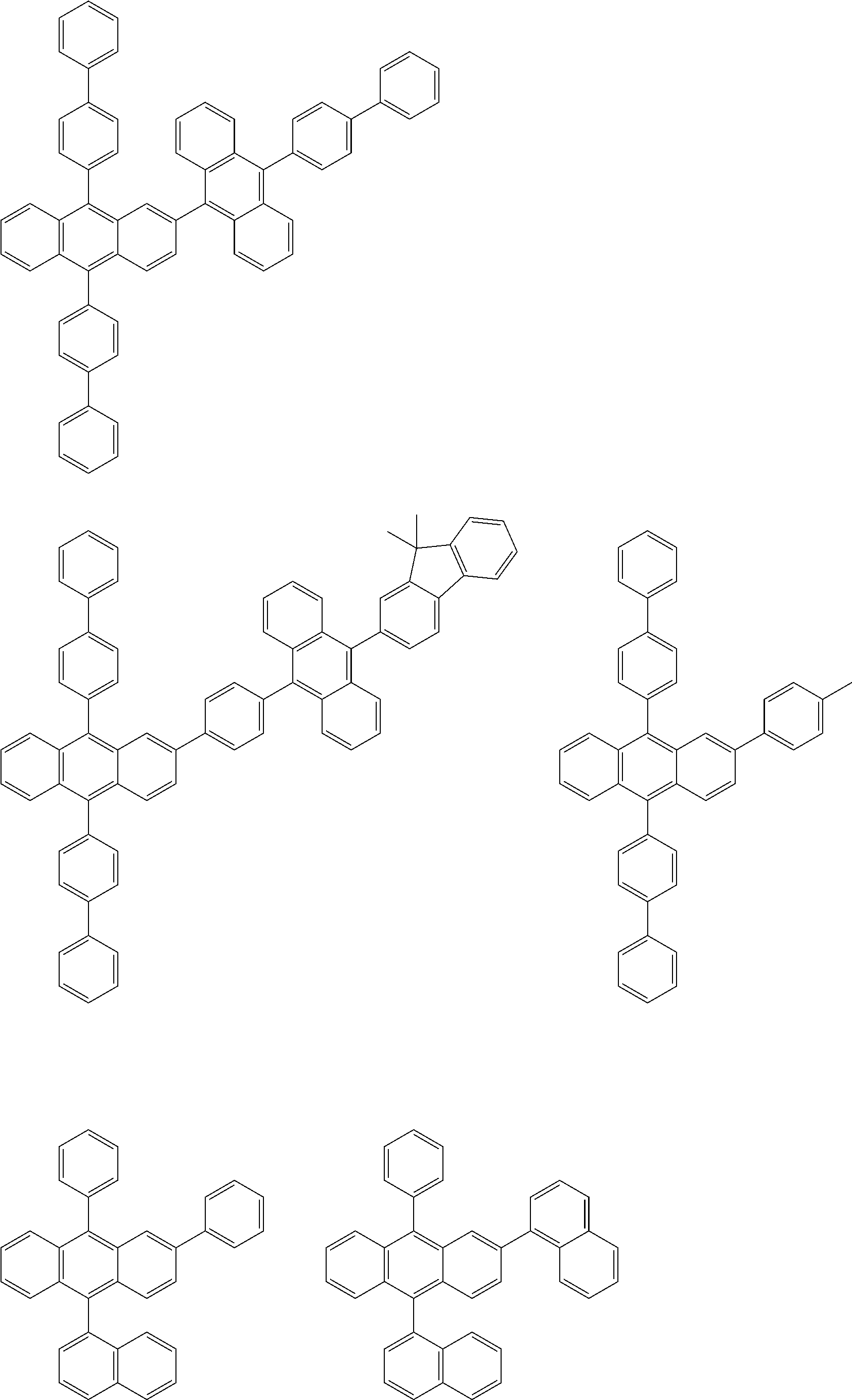


Second Compound
S 1(M1)>S 1(M2) (Numerical Formula 1).
T 77K(M1)>T 77K(M2) (Numerical Formula 4).
T 77K [eV]=1239.8/λedge Conversion Equation (F1):
S 1 [eV]=1239.85/λedge Conversion Equation (F2):


S 1(M3)>S 1(M1) (Numerical Formula 2).


S 1(M3)>S 1(M1)>S 1(M2) (Numerical Formula 3).
T 77K(M3)>T 77K(M1) (Numerical Formula 5).
T 77K(M3)>T 77K(M1)>T 77K(M2) (Numerical Formula 6).


| TABLE 2 | ||||
| Main Peak | ||||
| Molar | Wavelength | Absorption | ||
| Absorbance | of Emission | Peak | Stokes | |
| Coefficient | Spectrum | Wavelength | Shift | |
| Compound | [L/(mol · cm)] | [nm] | [nm] | [nm] |
| BD-1 | 30400 | 449 | 438 | 11 |
| BD-2 | 46600 | 457 | 450 | 7 |
| BD-3 | 41100 | 457 | 445 | 12 |
| BD-4 | 39200 | 466 | 452 | 14 |
| BD-5 | 44600 | 460 | 447 | 13 |
| BD-6 | 53400 | 462 | 448 | 14 |
| BD-7 | 56000 | 461 | 448 | 13 |
| TABLE 3 | ||||
| EQE | λp | |||
| Second Compound | [%] | [nm] | ||
| Example 1-1 | BD-1 (BD-1a, BD-1b) | 10.9 | 456 | ||
| Example 1-2 | BD-5 | 9.6 | 466 | ||
| Example 1-3 | BD-6 | 9.9 | 468 | ||
| Comparative 1-1 | TBPe | 8.7 | 464 | ||
| TABLE 4 | ||||
| EQE | λp | |||
| Second Compound | [%] | [nm] | ||
| Example 2-1 | BD-2 | 14.6 | 463 | ||
| Example 2-2 | BD-3 | 15.2 | 462 | ||
| Example 2-3 | BD-4 | 14.3 | 471 | ||
| Example 2-4 | BD-5 | 15.1 | 465 | ||
| Example 2-4 | BD-6 | 14.9 | 467 | ||
| TABLE 5 | ||||
| EQE | λp | |||
| Second Compound | [%] | [nm] | ||
| Example 3-1 | BD-2 | 7.9 | 463 | ||
| Comparative 3-1 | TNPe | 5.4 | 463 | ||
Claims (19)


S 1(M1)>S 1(M2) (Numerical Formula 1).


S 1(M3)>S 1(M1) (Numerical Formula 2).
Applications Claiming Priority (7)
| Application Number | Priority Date | Filing Date | Title |
|---|---|---|---|
| JP2016-219251 | 2016-11-09 | ||
| JP2016219251 | 2016-11-09 | ||
| JPJP2016-219251 | 2016-11-09 | ||
| JP2017-160667 | 2017-08-23 | ||
| JP2017160667 | 2017-08-23 | ||
| JPJP2017-160667 | 2017-08-23 | ||
| PCT/JP2017/040426 WO2018088472A1 (en) | 2016-11-09 | 2017-11-09 | Compound, composition, organic electroluminescent element, and electronic appliance |
Publications (2)
| Publication Number | Publication Date |
|---|---|
| US20190337872A1 US20190337872A1 (en) | 2019-11-07 |
| US11618722B2 true US11618722B2 (en) | 2023-04-04 |
Family
ID=62109861
Family Applications (1)
| Application Number | Title | Priority Date | Filing Date |
|---|---|---|---|
| US16/348,070 Active 2040-01-16 US11618722B2 (en) | 2016-11-09 | 2017-11-09 | Compound, composition, organic electroluminescent element, and electronic appliance |
Country Status (3)
| Country | Link |
|---|---|
| US (1) | US11618722B2 (en) |
| JP (1) | JPWO2018088472A1 (en) |
| WO (1) | WO2018088472A1 (en) |
Families Citing this family (14)
| Publication number | Priority date | Publication date | Assignee | Title |
|---|---|---|---|---|
| WO2018186462A1 (en) * | 2017-04-07 | 2018-10-11 | コニカミノルタ株式会社 | Fluorescent compound, organic material composition, light emitting film, organic electroluminescent element material, and organic electroluminescent element |
| KR20200139684A (en) * | 2018-04-05 | 2020-12-14 | 이데미쓰 고산 가부시키가이샤 | Organic electroluminescence device and electronic device |
| CN111372918B (en) | 2018-07-27 | 2023-09-05 | 出光兴产株式会社 | Compound, material for organic electroluminescent element, organic electroluminescent element, and electronic device |
| US11696495B2 (en) * | 2018-08-06 | 2023-07-04 | Lg Display Co., Ltd. | Organic emitting compound, and organic light emitting diode and organic light emitting display device including the same |
| CN110903158A (en) * | 2018-09-18 | 2020-03-24 | 上海和辉光电有限公司 | Organic luminescent material containing anthracene derivative, preparation method thereof and electroluminescent device |
| EP3754734A4 (en) * | 2018-09-20 | 2021-06-30 | Lg Chem, Ltd. | ORGANIC LIGHT DIODE |
| KR102794030B1 (en) * | 2018-12-14 | 2025-04-09 | 엘지디스플레이 주식회사 | Organic compound, and Organic light emitting diode and Organic light emitting display device including the same |
| US20220289704A1 (en) | 2019-08-08 | 2022-09-15 | Idemitsu Kosan Co.,Ltd. | Organic electroluminescent element and electronic device using same |
| EP3859809B1 (en) * | 2020-01-30 | 2023-12-20 | Samsung Display Co., Ltd. | Light-emitting device and electronic apparatus |
| JP7682628B2 (en) | 2020-12-25 | 2025-05-26 | キヤノン株式会社 | Organic compounds, organic light-emitting devices, display devices, photoelectric conversion devices, electronic devices, lighting devices, moving objects, and exposure light sources |
| CN112961166B (en) * | 2021-03-07 | 2022-02-25 | 苏州大学 | A kind of method for catalyzing the preparation of pyrano[2,3-b]indol-2-one compound |
| CN113321677B (en) * | 2021-06-30 | 2023-05-05 | 京东方科技集团股份有限公司 | Thermal-activation delay fluorescent material, organic light-emitting device and display device |
| WO2023090404A1 (en) * | 2021-11-18 | 2023-05-25 | 東ソー株式会社 | Condensed ring fluorene compound, material for organic electroluminescent element, and organic electroluminescent element |
| CN116332807A (en) * | 2023-03-24 | 2023-06-27 | 安徽秀朗新材料科技有限公司 | Production process of 3- (trifluoromethyl sulfonyl) -2-methyl naphthoate |
Citations (22)
| Publication number | Priority date | Publication date | Assignee | Title |
|---|---|---|---|---|
| US20040076853A1 (en) * | 2002-04-24 | 2004-04-22 | Eastman Kodak Company | Organic light-emitting diode devices with improved operational stability |
| JP2006151931A (en) | 2004-11-30 | 2006-06-15 | Tdk Corp | Aza-benzoanthracene compound and its manufacturing method |
| WO2010018842A1 (en) | 2008-08-12 | 2010-02-18 | 出光興産株式会社 | Benzofluoranthene derivative and organic electroluminescence element comprising same |
| US20100039027A1 (en) * | 2007-02-19 | 2010-02-18 | Idemitsu Kosan Co., Ltd | Organic electroluminescence device |
| US20110114889A1 (en) * | 2008-07-29 | 2011-05-19 | Merck Patent Gmbh | Compounds for electronic devices |
| WO2011081429A2 (en) | 2009-12-30 | 2011-07-07 | 주식회사 두산 | Organic compound, and organic electroluminescent device using same |
| WO2011096272A1 (en) | 2010-02-02 | 2011-08-11 | Canon Kabushiki Kaisha | Novel organic compound and organic light-emitting device including the same |
| WO2012153780A1 (en) | 2011-05-11 | 2012-11-15 | 出光興産株式会社 | Novel compound, material for organic electroluminescence device, and organic electroluminescence device |
| WO2013038650A1 (en) | 2011-09-13 | 2013-03-21 | 出光興産株式会社 | Fused heterocyclic aromatic derivative, organic electroluminescence element material, and organic electroluminescence element using same |
| WO2013180241A1 (en) | 2012-06-01 | 2013-12-05 | 出光興産株式会社 | Organic electroluminescence element and material for organic electroluminescence element |
| WO2014092083A1 (en) | 2012-12-10 | 2014-06-19 | 出光興産株式会社 | Organic electroluminescent element |
| WO2014104346A1 (en) | 2012-12-28 | 2014-07-03 | 出光興産株式会社 | Organic electroluminescent element |
| WO2014157574A1 (en) | 2013-03-27 | 2014-10-02 | 出光興産株式会社 | Condensed fluoranthene compound, material for organic electroluminescent element using this compound, organic electroluminescent element using this material, and electronic device |
| CN104829521A (en) | 2013-12-02 | 2015-08-12 | 北京鼎材科技有限公司 | 10,15-dibenzylbenzofluorenocarbazole derivative and application thereof |
| US9120748B2 (en) * | 2006-11-15 | 2015-09-01 | Idemitsu Kosan Co., Ltd. | Fluoranthene compound, organic electroluminescence device using the same, and solution containing organic electroluminescence material |
| WO2015151965A1 (en) | 2014-03-31 | 2015-10-08 | 出光興産株式会社 | Organic electroluminescent element and electronic device |
| KR20160038310A (en) | 2014-09-30 | 2016-04-07 | (주)더블유에스 | fused fluoranthene derivatives and organic electroluminescent device including the same |
| JP2016066758A (en) | 2014-09-25 | 2016-04-28 | 山本化成株式会社 | Organic transistor |
| JP2016129262A (en) | 2013-12-26 | 2016-07-14 | 出光興産株式会社 | Organic electroluminescent element and electronic device |
| US20170062731A1 (en) | 2013-12-26 | 2017-03-02 | Idemitsu Kosan Co., Ltd. | Organic electroluminescent element and electronic device |
| WO2017146191A1 (en) | 2016-02-24 | 2017-08-31 | 出光興産株式会社 | Organic electroluminescent element, and electronic device |
| US20180123049A1 (en) * | 2015-03-27 | 2018-05-03 | Industry-Academic Cooperation Foundation, Dankook University | Ortho-substituted thermally activated delayed fluorescence material and organic light-emitting device comprising same |
Family Cites Families (1)
| Publication number | Priority date | Publication date | Assignee | Title |
|---|---|---|---|---|
| JP6305162B2 (en) * | 2014-03-31 | 2018-04-04 | Kyb株式会社 | Valve device |
-
2017
- 2017-11-09 JP JP2018550250A patent/JPWO2018088472A1/en active Pending
- 2017-11-09 WO PCT/JP2017/040426 patent/WO2018088472A1/en not_active Ceased
- 2017-11-09 US US16/348,070 patent/US11618722B2/en active Active
Patent Citations (27)
| Publication number | Priority date | Publication date | Assignee | Title |
|---|---|---|---|---|
| US20040076853A1 (en) * | 2002-04-24 | 2004-04-22 | Eastman Kodak Company | Organic light-emitting diode devices with improved operational stability |
| JP2006151931A (en) | 2004-11-30 | 2006-06-15 | Tdk Corp | Aza-benzoanthracene compound and its manufacturing method |
| US9120748B2 (en) * | 2006-11-15 | 2015-09-01 | Idemitsu Kosan Co., Ltd. | Fluoranthene compound, organic electroluminescence device using the same, and solution containing organic electroluminescence material |
| US20100039027A1 (en) * | 2007-02-19 | 2010-02-18 | Idemitsu Kosan Co., Ltd | Organic electroluminescence device |
| US20110114889A1 (en) * | 2008-07-29 | 2011-05-19 | Merck Patent Gmbh | Compounds for electronic devices |
| WO2010018842A1 (en) | 2008-08-12 | 2010-02-18 | 出光興産株式会社 | Benzofluoranthene derivative and organic electroluminescence element comprising same |
| WO2011081429A2 (en) | 2009-12-30 | 2011-07-07 | 주식회사 두산 | Organic compound, and organic electroluminescent device using same |
| WO2011081429A3 (en) | 2009-12-30 | 2011-12-01 | 주식회사 두산 | Organic compound, and organic electroluminescent device using same |
| WO2011096272A1 (en) | 2010-02-02 | 2011-08-11 | Canon Kabushiki Kaisha | Novel organic compound and organic light-emitting device including the same |
| US20120299806A1 (en) | 2010-02-02 | 2012-11-29 | Canon Kabushiki Kaisha | Novel organic compound and organic light-emitting device including the same |
| WO2012153780A1 (en) | 2011-05-11 | 2012-11-15 | 出光興産株式会社 | Novel compound, material for organic electroluminescence device, and organic electroluminescence device |
| WO2013038650A1 (en) | 2011-09-13 | 2013-03-21 | 出光興産株式会社 | Fused heterocyclic aromatic derivative, organic electroluminescence element material, and organic electroluminescence element using same |
| WO2013180241A1 (en) | 2012-06-01 | 2013-12-05 | 出光興産株式会社 | Organic electroluminescence element and material for organic electroluminescence element |
| WO2014092083A1 (en) | 2012-12-10 | 2014-06-19 | 出光興産株式会社 | Organic electroluminescent element |
| WO2014104346A1 (en) | 2012-12-28 | 2014-07-03 | 出光興産株式会社 | Organic electroluminescent element |
| US20160322587A1 (en) | 2013-03-27 | 2016-11-03 | Idemitsu Kosan Co., Ltd. | Condensed fluoranthene compound, material for organic electroluminescent element using this compound, organic electroluminescent element using this material, and electronic device |
| US20150228904A1 (en) | 2013-03-27 | 2015-08-13 | Idemitsu Kosan Co., Ltd. | Condensed fluoranthene compound, material for organic electroluminescent element using this compound, organic electroluminescent element using this material, and electronic device |
| WO2014157574A1 (en) | 2013-03-27 | 2014-10-02 | 出光興産株式会社 | Condensed fluoranthene compound, material for organic electroluminescent element using this compound, organic electroluminescent element using this material, and electronic device |
| CN104829521A (en) | 2013-12-02 | 2015-08-12 | 北京鼎材科技有限公司 | 10,15-dibenzylbenzofluorenocarbazole derivative and application thereof |
| US20170062731A1 (en) | 2013-12-26 | 2017-03-02 | Idemitsu Kosan Co., Ltd. | Organic electroluminescent element and electronic device |
| JP2016129262A (en) | 2013-12-26 | 2016-07-14 | 出光興産株式会社 | Organic electroluminescent element and electronic device |
| WO2015151965A1 (en) | 2014-03-31 | 2015-10-08 | 出光興産株式会社 | Organic electroluminescent element and electronic device |
| US20170110667A1 (en) | 2014-03-31 | 2017-04-20 | Idemitsu Kosan Co., Ltd. | Organic electroluminescent element and electronic device |
| JP2016066758A (en) | 2014-09-25 | 2016-04-28 | 山本化成株式会社 | Organic transistor |
| KR20160038310A (en) | 2014-09-30 | 2016-04-07 | (주)더블유에스 | fused fluoranthene derivatives and organic electroluminescent device including the same |
| US20180123049A1 (en) * | 2015-03-27 | 2018-05-03 | Industry-Academic Cooperation Foundation, Dankook University | Ortho-substituted thermally activated delayed fluorescence material and organic light-emitting device comprising same |
| WO2017146191A1 (en) | 2016-02-24 | 2017-08-31 | 出光興産株式会社 | Organic electroluminescent element, and electronic device |
Non-Patent Citations (10)
| Title |
|---|
| Appl. Phys. Letters, 101, (2012), pp. 093306-1 to 09336-4. (Year: 2012). * |
| Chem. Commun., (2013), 49, pp. 10385-10387. (Year: 2013). * |
| Chinaya Adachi, "Device Physics of Organic Semiconductors" Kodansha Ltd., Apr. 1, 2012, pp. 261-268 (with English Translation). |
| Hajime Nakanotani, et al., "High-Efficiency Organic Light-Emitting Diodes with Fluorescent Emitters" Nature Communications, DOI: 10.1038/ncomms5016, 2014, pp. 1-7. |
| Keiro Nasu, et al., "A Highly Luminescent Spiro-Anthracenone-Based Organic Light-Emitting Diode Exhibiting Thermally Activated Delayed Fluorescence" The Royal Society of Chemistry, Chem. Commun., vol. 49, 2013, pp. 10385-10387. |
| Kung et al., Chem. Eur. J. (2010), vol. 16, pp. 5909-5919. (Year: 2010). * |
| Nature Communications, (2014), 5:4016, pp. 1-7. (Year: 2014). * |
| Qisheng Zhang, et al., "Efficient Blue Organic Light-Emitting Diodes Employing Thermally Activated Delayed Fluorescence" Nature Photonics, vol. 8, No. 4, Apr. 2014, pp. 326-332 and cover pages. |
| Registry [online], US: American Chemical Society [retrieved on Dec. 8, 2017], Retrieved from: SIN, CAS RN 1914968-52-7, 1914968-18-5. 1 page. |
| Sae Youn Lee, et al., "High-Efficiency Organic Light-Emitting Diodes Utilizing Thermally Activated Delayed Fluorescence from Triazine-Based Donor-Acceptor Hybrid Molecules" Applied Physics Letters, vol. 101, 2012, pp. 093306-1-093306-4 and cover page. |
Also Published As
| Publication number | Publication date |
|---|---|
| WO2018088472A1 (en) | 2018-05-17 |
| JPWO2018088472A1 (en) | 2019-10-03 |
| US20190337872A1 (en) | 2019-11-07 |
Similar Documents
| Publication | Publication Date | Title |
|---|---|---|
| US11618722B2 (en) | Compound, composition, organic electroluminescent element, and electronic appliance | |
| US10547009B2 (en) | Organic electroluminescent element, electronic device and compound | |
| US11968894B2 (en) | Organic electroluminescent element, material for organic electroluminescent elements, and electronic device | |
| US9997717B2 (en) | Organic electroluminescence device and electronic device | |
| US11482681B2 (en) | Compound, material for organic electroluminescence element, organic electroluminescence element, and electronic device | |
| US11043638B2 (en) | Organic electroluminescence device and electronic device | |
| US20200035922A1 (en) | Organic electroluminescence element and electronic device | |
| US11201297B2 (en) | Organic electroluminescence device and electronic device | |
| US10249826B2 (en) | Compound, organic electroluminescent element and electronic device | |
| EP3422431B1 (en) | Organic electroluminescent element and electronic device | |
| US12486452B2 (en) | Organic electroluminescent element and electronic device | |
| US11271164B2 (en) | Compound, composition, organic electroluminescent element and electronic device | |
| US12435269B2 (en) | Organic electroluminescent element and electronic appliance | |
| US20210074925A1 (en) | Organic electroluminescent element and electronic device | |
| US20220388991A1 (en) | Compound, material for organic electroluminescent element, organic electroluminescent element, and electronic device | |
| US12274168B2 (en) | Compound, material for organic electroluminescent element, organic electroluminescent element, and electronic appliance | |
| US20190013476A1 (en) | Organic electroluminescent element, and electronic device | |
| US20220263030A1 (en) | Organic electroluminescent element and electronic device | |
| US20220081450A1 (en) | Organic electroluminescent element, compound, material for organic electroluminescent element, and electronic device | |
| US12302757B2 (en) | Organic electroluminescence element and electronic device | |
| US20220238815A1 (en) | Organic electroluminescent element, compound, and electronic appliance | |
| US11944009B2 (en) | Compound, material for organic electroluminescent element, organic electroluminescent element, and electronic device | |
| US12575319B2 (en) | Organic electroluminescence device and electronic device | |
| US20230301188A1 (en) | Organic electroluminescent element, organic electroluminescent light-emitting device, and electronic equipment | |
| US11424414B2 (en) | Organic electroluminescent element, electronic device, and compound |
Legal Events
| Date | Code | Title | Description |
|---|---|---|---|
| FEPP | Fee payment procedure |
Free format text: ENTITY STATUS SET TO UNDISCOUNTED (ORIGINAL EVENT CODE: BIG.); ENTITY STATUS OF PATENT OWNER: LARGE ENTITY |
|
| AS | Assignment |
Owner name: IDEMITSU KOSAN CO.,LTD., JAPAN Free format text: ASSIGNMENT OF ASSIGNORS INTEREST;ASSIGNORS:SAITO, MASATOSHI;YOSHIDA, KEI;KAWAMURA, YUICHIRO;AND OTHERS;SIGNING DATES FROM 20190425 TO 20190518;REEL/FRAME:049364/0229 |
|
| STPP | Information on status: patent application and granting procedure in general |
Free format text: NON FINAL ACTION MAILED |
|
| STPP | Information on status: patent application and granting procedure in general |
Free format text: RESPONSE TO NON-FINAL OFFICE ACTION ENTERED AND FORWARDED TO EXAMINER |
|
| STPP | Information on status: patent application and granting procedure in general |
Free format text: FINAL REJECTION MAILED |
|
| STPP | Information on status: patent application and granting procedure in general |
Free format text: RESPONSE AFTER FINAL ACTION FORWARDED TO EXAMINER |
|
| STPP | Information on status: patent application and granting procedure in general |
Free format text: NOTICE OF ALLOWANCE MAILED -- APPLICATION RECEIVED IN OFFICE OF PUBLICATIONS |
|
| STCF | Information on status: patent grant |
Free format text: PATENTED CASE |