US11608108B2 - Automatic steering system and automatic steering method - Google Patents
Automatic steering system and automatic steering method Download PDFInfo
- Publication number
- US11608108B2 US11608108B2 US17/345,540 US202117345540A US11608108B2 US 11608108 B2 US11608108 B2 US 11608108B2 US 202117345540 A US202117345540 A US 202117345540A US 11608108 B2 US11608108 B2 US 11608108B2
- Authority
- US
- United States
- Prior art keywords
- value
- control term
- calculated
- target steering
- steering angle
- Prior art date
- Legal status (The legal status is an assumption and is not a legal conclusion. Google has not performed a legal analysis and makes no representation as to the accuracy of the status listed.)
- Active
Links
Images


Classifications
-
- B—PERFORMING OPERATIONS; TRANSPORTING
- B62—LAND VEHICLES FOR TRAVELLING OTHERWISE THAN ON RAILS
- B62D—MOTOR VEHICLES; TRAILERS
- B62D15/00—Steering not otherwise provided for
- B62D15/02—Steering position indicators ; Steering position determination; Steering aids
- B62D15/025—Active steering aids, e.g. helping the driver by actively influencing the steering system after environment evaluation
-
- B—PERFORMING OPERATIONS; TRANSPORTING
- B62—LAND VEHICLES FOR TRAVELLING OTHERWISE THAN ON RAILS
- B62D—MOTOR VEHICLES; TRAILERS
- B62D6/00—Arrangements for automatically controlling steering depending on driving conditions sensed and responded to, e.g. control circuits
- B62D6/001—Arrangements for automatically controlling steering depending on driving conditions sensed and responded to, e.g. control circuits the torque NOT being among the input parameters
-
- B—PERFORMING OPERATIONS; TRANSPORTING
- B62—LAND VEHICLES FOR TRAVELLING OTHERWISE THAN ON RAILS
- B62D—MOTOR VEHICLES; TRAILERS
- B62D5/00—Power-assisted or power-driven steering
- B62D5/04—Power-assisted or power-driven steering electrical, e.g. using an electric servo-motor connected to, or forming part of, the steering gear
- B62D5/0457—Power-assisted or power-driven steering electrical, e.g. using an electric servo-motor connected to, or forming part of, the steering gear characterised by control features of the drive means as such
- B62D5/046—Controlling the motor
-
- B—PERFORMING OPERATIONS; TRANSPORTING
- B62—LAND VEHICLES FOR TRAVELLING OTHERWISE THAN ON RAILS
- B62D—MOTOR VEHICLES; TRAILERS
- B62D5/00—Power-assisted or power-driven steering
- B62D5/04—Power-assisted or power-driven steering electrical, e.g. using an electric servo-motor connected to, or forming part of, the steering gear
- B62D5/0457—Power-assisted or power-driven steering electrical, e.g. using an electric servo-motor connected to, or forming part of, the steering gear characterised by control features of the drive means as such
- B62D5/0481—Power-assisted or power-driven steering electrical, e.g. using an electric servo-motor connected to, or forming part of, the steering gear characterised by control features of the drive means as such monitoring the steering system, e.g. failures
- B62D5/049—Power-assisted or power-driven steering electrical, e.g. using an electric servo-motor connected to, or forming part of, the steering gear characterised by control features of the drive means as such monitoring the steering system, e.g. failures detecting sensor failures
-
- B—PERFORMING OPERATIONS; TRANSPORTING
- B62—LAND VEHICLES FOR TRAVELLING OTHERWISE THAN ON RAILS
- B62D—MOTOR VEHICLES; TRAILERS
- B62D6/00—Arrangements for automatically controlling steering depending on driving conditions sensed and responded to, e.g. control circuits
- B62D6/002—Arrangements for automatically controlling steering depending on driving conditions sensed and responded to, e.g. control circuits computing target steering angles for front or rear wheels
- B62D6/003—Arrangements for automatically controlling steering depending on driving conditions sensed and responded to, e.g. control circuits computing target steering angles for front or rear wheels in order to control vehicle yaw movement, i.e. around a vertical axis
-
- B—PERFORMING OPERATIONS; TRANSPORTING
- B62—LAND VEHICLES FOR TRAVELLING OTHERWISE THAN ON RAILS
- B62D—MOTOR VEHICLES; TRAILERS
- B62D5/00—Power-assisted or power-driven steering
- B62D5/04—Power-assisted or power-driven steering electrical, e.g. using an electric servo-motor connected to, or forming part of, the steering gear
- B62D5/0457—Power-assisted or power-driven steering electrical, e.g. using an electric servo-motor connected to, or forming part of, the steering gear characterised by control features of the drive means as such
- B62D5/0481—Power-assisted or power-driven steering electrical, e.g. using an electric servo-motor connected to, or forming part of, the steering gear characterised by control features of the drive means as such monitoring the steering system, e.g. failures
- B62D5/0484—Power-assisted or power-driven steering electrical, e.g. using an electric servo-motor connected to, or forming part of, the steering gear characterised by control features of the drive means as such monitoring the steering system, e.g. failures for reaction to failures, e.g. limp home
Definitions
- the present disclosure relates to a system and a method to execute automatic steering control of a vehicle.
- JP2016-084092A discloses an autonomous driving system in which fail-safe control is executed during the execution of steering assist control.
- the steering assist control is a control that assists a steering of a driver the vehicle such that the vehicle runs along a target pass line.
- the fail-safe control is executed when an anomaly in a yaw motion control system is predicted.
- the target pass line is corrected considering a delay in a response of the driver.
- a target steering angle is calculated such that the vehicle runs along the corrected target pass line.
- One object of the present disclosure is to provide a technique capable of ensuring the tracking performance to the target pass line even when an anomaly occurs in the acceleration sensor during the execution of the automatic steering control.
- a first aspect is an automatic steering system in which automatic steering control of a vehicle is executed.
- the automatic steering system comprises a detection device and a controller.
- the detection device is configured to detect driving environment information of the vehicle.
- the controller is configured to execute target steering angle calculation processing to calculate a target steering angle in the automatic steering control based on the driving environment information.
- the detection device includes an acceleration sensor, a vehicle speed sensor and a yaw rate sensor.
- the acceleration sensor is configured to detect lateral acceleration of the vehicle.
- the vehicle speed sensor is configured to detect driving speed of the vehicle.
- the yaw rate sensor is configured to detect yaw rate of the vehicle.
- the controller is further configured to calculate a learning value of the lateral acceleration.
- the learning value is calculated based on an error of a detected value of the lateral acceleration and an estimation value of the lateral acceleration calculated by using the driving speed and the yaw rate.
- the controller judges whether or not the acceleration sensor is normal.
- the controller calculates the target steering angle by using the detected value.
- the controller switches the lateral acceleration used to calculate the target steering angle from the detected value to a backup value of the lateral acceleration.
- the backup value is calculated by using the estimation value and the learning value that is calculated before a timing at which the acceleration sensor is judged to abnormal.
- a second aspect further has the following features in the first aspect.
- the controller is configured to calculate the target steering angle by using a slant angle feedforward control term that is set in accordance with a slant angle of a road.
- the slant angle feedforward control term is calculated by using the detected value.
- the slant angle feedforward control term is calculated by using the backup value after a predetermined transition period that is reckoning from the timing.
- the slant angle feedforward control term is calculated by using an intermediate value that gradually approaches the backup value from the detected value.
- the transition period is set to a longer period as an absolute value of the slant angle feedforward control term calculated by using the detected value immediately before the timing decreases.
- a third aspect further has the following features in the first aspect.
- the controller is configured to:
- the line following control term includes a time-integrated integral control term obtained by integrating the deviation amount over time.
- the controller is further configured to:
- a control gain of the time-integrated integral control term is increased as compared with a case where the slant angle feedforward control term is used.
- a fourth aspect is an automatic steering method in which automatic steering control of a vehicle is executed by a controller.
- the vehicle comprises a detection device which is configured to detect driving environment information of the vehicle.
- the detection device includes an acceleration sensor, a vehicle speed sensor and a yaw rate sensor.
- the acceleration sensor is configured to detect lateral acceleration of the vehicle.
- the vehicle speed sensor is configured to detect driving speed of the vehicle.
- the yaw rate sensor is configured to detect yaw rate of the vehicle.
- the method comprising the steps of:
- the learning value is calculated based on an error of a detected value of the lateral acceleration and an estimation value of the lateral acceleration calculated by using the driving speed and the yaw rate.
- the step of executing the target steering angle calculation processing includes the steps of:
- the backup value is calculated by using the estimation value and the learning value that is calculated before a timing at which the acceleration sensor is judged to abnormal.
- a fifth aspect further has the following features in the fourth aspect.
- the step of executing the target steering angle calculation processing further includes the step of calculating the target steering angle by using a slant angle feedforward control term that is set in accordance with a slant angle of a road.
- the slant angle feedforward control term is calculated by using the detected value.
- the slant angle feedforward control term is calculated by using the backup value after a predetermined transition period that is reckoning from the timing.
- the slant angle feedforward control term is calculated by using an intermediate value that gradually approaches the backup value from the detected value.
- the transition period is set to a longer period as an absolute value of the slant angle feedforward control term calculated by using the detected value immediately before the timing decreases.
- a sixth aspect further has the following features in the fourth aspect.
- the step of executing the target steering angle calculation processing includes the steps of:
- calculating, based on the driving environment information, a line following control term indicating a control term for reducing deviation amount of the vehicle to target pass line is calculated, the line following control term includes a time-integrated integral control term obtained by integrating the deviation amount over time;
- a control gain of the time-integrated integral control term is increased as compared with a case where the slant angle feedforward control term is used.
- the target steering angle is calculated by using the detected value of the lateral acceleration by the horizontal acceleration sensor. If it is judged that the acceleration sensor is abnormal, the target steering angle is calculated by using the backup value of the lateral acceleration. This backup value is calculated based on the estimation value of the lateral acceleration and the learning value, and this learning value is calculated based on the detected value and the error of the estimation value. Therefore, it is expected that the target steering angle calculated by using the backup value is approximately close to the target steering angle calculated by using the detected value.
- the first of fourth aspect even if it is judged that the acceleration sensor is abnormal, it is possible to continuously execute the automatic steering control with substantially the same accuracy as the automatic steering control that was executed before the judgement. Therefore, according to the first or fourth aspect, even when an anomaly occurs in the acceleration sensor during the execution of the automatic steering control, it is possible to ensure the tracking performance to the target pass line.
- the predetermined transition period that is reckoning from the timing of the judgement is set. Further, in this transition period, the target steering angle is calculated by using the intermediate value gradually approaching backup the value from the detected value. This transition period is set to a longer period as the absolute value of the slant angle feedforward control term that is calculated by using the detected value immediately before the timing decreases.
- the slant angle feedforward control term is set in accordance with the slant angle of the road, a smaller absolute value means that a road surface is relatively flat and a position of the vehicle is hardly shifted in an inclination direction. Therefore, when the absolute value is small, it is expected that the tracking performance to the target pass line is ensured even if the transition period is set for a relatively long period. Therefore, according to the second or fifth aspect in which the target steering angle is calculated by using the intermediate value in a relatively long transition period, it is possible to reduce a rate of change in the target steering angle accompanying a switching from the detected value to the backup value. Therefore, it is possible to suppress the occupant of the vehicle from feeling of a strangeness due to the change in the target steering angle.
- the target steering angle is calculated by using the time-integrated integral control term instead of the slant angle feedforward control term.
- the control gain of the time-integrated integral control term is increased as compared with the case where the slant angle feedforward control term is used.
- the time-integrated integral control term is a control term that integrates the deviation amount for the target pass line of the vehicle over time. Therefore, if the control gain of the time-integrated integral control term is increased, speed at which the deviation amount is accumulated increases. Then, when the deviation amount increases, an effect of the time-integrated integral control term increases. Therefore, according to the third of sixth aspect, it is possible to compensate for a decrease in the tracking performance to the target pass line due to the disuse of the slant angle feedforward control term.
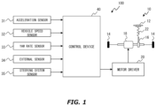
- FIG. 1 is a diagram showing a configuration example of an automatic steering system according to a first embodiment
- FIG. 2 is a block diagram showing a function configuration example of a controller shown in FIG. 1 ;
- FIG. 3 is a diagram illustrating an example of lane information
- FIG. 4 is a diagram showing a control configuration example of an automatic steering control part shown in FIG. 2 ;
- FIG. 5 is a flow chart showing a flow of calculation processing executed by a backup value calculation part shown in FIG. 2 ;
- FIG. 6 is a diagram illustrating an example of a relationship between lateral acceleration, steering angle, and driving speed
- FIG. 7 is a flow chart showing a flow of calculation processing of a target steering angle executed by the controller in the first embodiment
- FIG. 8 is a timing chart for explaining an effect by the first embodiment
- FIG. 9 is a timing chart explaining an outline of a second embodiment.
- FIG. 10 is a flow chart showing a flow of calculation processing of the target steering angle executed by the controller in the second embodiment.
- FIGS. 1 to 7 An automatic steering system of a first embodiment of the present disclosure will be explained by referring to FIGS. 1 to 7 .
- FIG. 1 is a diagram showing a configuration example of the automatic steering system according to the first embodiment.
- An automatic steering system 100 shown in FIG. 1 is mounted on a vehicle VH.
- the vehicle VH is, for example, a vehicle in which an internal combustion engine such as a diesel engine or a gasoline engine is used as a power source, an electronic vehicle in which an electric motor is used as the power source, or a hybrid vehicle including the internal combustion engine and the electric motor.
- the electric motor is driven by a battery such as a secondary cell, a hydrogen cell, a metallic fuel cell, and an alcohol fuel cell.
- the system 100 includes an EPS (Electronic Power Steering) device 10 .
- the EPS device 10 includes a steering wheel 12 , left and right tires 14 , 14 , a steering mechanism 16 , an electric motor 18 , and a motor driver 20 .
- the steering mechanism 16 includes, for example, a steering column shaft, a gear mechanism, and a linkage.
- the steering column shaft receives a rotational manipulation of the steering wheel 12 .
- the gear mechanism increases a steering force generated by the rotational manipulation inputted to a steering shaft.
- the linkage transmits the steering force transmitted from the gear mechanism to the left and right tires 14 and 14 .
- the electric motor 18 generates a torque by receiving a command current from the motor driver 20 , and applies it to the steering mechanism 16 .
- the electric motor 18 transmits the generated torque to a rack shaft of the gear mechanism.
- the EPS device 10 is configured as a rack-assisted EPS device.
- the EPS device 10 may be configured as a column-assisted EPS device for transmitting the generated torques to the steering column shaft.
- the EPS device 10 may be configured as a pinion assisted EPS device for transmitting the generated torques to a pinion shaft of the gear mechanism.
- the system 100 also includes various sensors.
- the various sensors include an internal sensor for acquiring information on a driving condition of the vehicle VH.
- Examples of the internal sensor include an acceleration sensor 31 , a vehicle speed sensor 32 and a yaw rate sensor 33 .
- the acceleration sensor 31 detects lateral acceleration Gy of the vehicle VH.
- a detected value of the lateral acceleration Gy is also referred to as a “detected value Gy_sen.”
- the vehicle speed sensor (or a wheel speed sensor) 32 detects driving speed V of the vehicle VH.
- the driving speed V is decomposed into a travel direction component Vx and a transverse direction component Vy of the vehicle VH.
- the yaw rate sensor 33 detects yaw rate ⁇ around a center of gravity axis generated when the vehicle VH is turned.
- Examples of the various sensors also include an external sensor 34 .
- the external sensor 34 acquires information on surroundings of the vehicle VH.
- Examples of the external sensor 34 include a camera and a radar.
- the camera captures a landscape in front of the vehicle VH.
- a radar illuminates an electromagnetic wave around the vehicle VH to detect a reflective wave.
- Examples of the radar include a millimeter wave radar, a microphone wave radar, and a laser radar.
- Examples of the various sensors also include a steering system sensor 35 .
- the steering system sensor 35 acquires information on an operating status of the steering wheel 12 .
- Examples of the steering system sensor 35 include a torque sensor.
- the torque sensor measures, for example, a torsion of a torsion bar in the steering column shaft and converts it into a torque. Horizontal direction of the torque is specified by a positive or a negative sign of the torque.
- the torque sensor measures a steering angle ⁇ in addition to the torque.
- the information obtained by the various sensors is collectively referred to as “driving environment information” of the vehicle VH.
- a sensor for detecting such the driving environment information corresponds to a “detection device” in the present application.
- the system 100 also includes a controller 40 .
- the controller 40 acquires the driving environment information and executes automatic steering control via a communication network built inside the vehicle VH.
- the controller 40 is typically a microcomputer having at least one memory and at least one processor.
- the memory stores various programs and maps used for the steering control.
- the processor reads and executes the programs from the memory to realize various functions related to the automatic steering control.
- the controller 40 may be composed of a plurality of microcomputers.
- the controller 40 provides a control amount to the motor driver 20 .
- This control amount is an amount to control the EPS device 10 (hereinafter also referred to as an “EPS control amount”).
- the EPS control amount is specified by a target steering angle ⁇ *, which will be described in detail later.
- the EPS control amount is expressed by current or torque.
- the controller 30 controls the torque applied from the electric motor 18 to steering mechanism 16 by adjusting the EPS control amount applied to the motor driver 20 .
- FIG. 2 is a block diagram showing a function configuration example of the controller 40 .
- the controller 40 includes an information acquisition part 41 , an automatic steering control part 42 , a fail-safe control part 43 , and a backup value calculation part 44 . These functions are realized when the processor of the controller 40 executes various control programs stored in the memory.
- the information acquisition part 41 captures signals related to the driving environment information from the various sensors.
- the information acquisition part 41 further processes the captured signals.
- the processing of the signals by the information acquisition part 41 includes processing to analyze image data from the external sensor 34 (especially, from the camera). In this analysis processing, a white lane formed on roads in front of the vehicle VH is recognized. In this analysis processing, lane information required to execute the automatic steering control is generated based on the recognized white lane.
- FIG. 3 is a diagram illustrating an example of the lane information.
- the lane information includes information on a left white lane LL and a right white lane LR shown in FIG. 3 .
- the Left white lane LL and the right white lane LR are lane division lines recognized by the analysis processing of the image data.
- the lane information also includes information on a reference line RL.
- the reference line RL is set, for example, at a position in a central of the left white lane LL and the right white lane LR. In another example, the reference line RL is set to a position close to the right white lane LR by a predetermined distance from the left white lane LL.
- the reference line RL is set to a target pass line of the vehicle VH.
- the lane information also includes information on a curvature CL of the target pass line.
- CL curvature radius
- the lane information also includes information on a lateral deviation Dy and a yaw angle ⁇ y.
- the lateral deviation Dy is a distance in a lane width direction from a reference position RP of the vehicle VH to the reference line RL as the target pass line. That is, the lateral deviation Dy is a deviation amount of the vehicle VH to the target pass line.
- the reference position RP is set at any position of the vehicle VH.
- the yaw angle ⁇ y is a slip angle of a direction of the vehicle VH relative to the target pass line.
- the yaw angle ⁇ y is calculated as follows, for example. First, a virtual line VL extending in a longitudinal direction of the vehicle VH is set.
- a tangent line TL of the target pass line passing through an intersection point between the virtual line VL and the target pass line is set.
- An angle formed between the virtual line VL and the tangent line TL is the yaw angle ⁇ y.
- the information acquisition part 41 transmits the driving environment information and the lane information to the automatic steering control part 42 .
- the automatic steering control part 42 executes the automatic steering control based on the driving environment information and the lane information.
- FIG. 4 is a diagram showing a control configuration example of the automatic steering control part 42 .
- the automatic steering control part 42 includes a FF (Feed-Forward) control portion 42 a , a FB (Feed-Back) control portion 42 b , a lateral deviation integral control part 42 c , an adder part 42 d to 42 f , a gain multiplier part 42 g and 42 h , a slant FF control part 42 i , and a straight-ahead integration control portion 42 j.
- the FF control part 42 a calculates a FF control term Ay 1 of a target lateral acceleration Ay* that is set based on the curvature CL by using the following equation (1).
- Ay 1 CL ⁇ V 2 ⁇ K 1 (1)
- V is the driving speed and K 1 is a FF control gain.
- the FB control part 42 b calculates a FB control term Ay 2 of the target lateral acceleration Ay* that is set based on a lateral deviation Dy by using the following equation (2).
- the FB control part 42 b also calculates a FB control term Ay 3 of the target lateral acceleration Ay* that is set based on a component Vy in a transverse direction of the driving speed V by using the following equation (3).
- Ay 2 Dy ⁇ K 2 (2)
- Ay 3 Vy ⁇ K 3 (3)
- K 2 is a lateral deviation FB control gain.
- K 3 is a lateral speed FB control gain.
- the lateral deviation integral control part 42 c calculates an integral control term Ay 4 of the target lateral acceleration Ay* that is obtained by integrating the lateral deviation Dy with time by using the following equation (4).
- Ay 4 Ay 4( n ⁇ 1)+ Dy ⁇ t ⁇ K 4 (4)
- Ay 4 ( n ⁇ 1) represents an integral control term calculated in a calculation period immediately before the calculation of the Ay 4
- t represents the calculation period
- K 4 represents a lateral deviation integral control gain.
- the lateral deviation integral control gain K 4 functions as a constant for setting a degree to which the integral control term Ay 4 can be changed per unit time (i.e., per one calculation period).
- the integral control term Ay 4 is an integral value of the lateral deviation Dy in proportion to the lateral deviation integral control gain K 4 . Therefore, the greater the lateral deviation integral control gain K 4 , the higher the speed at which the lateral deviation Dy is accumulated.
- the adder part 42 d calculates a target lateral acceleration Ay* by using the following equation (5).
- Ay* Ay 1+ Ay 2+ Ay 3+ Ay 4 (5)
- the target lateral acceleration Ay* is calculated by a sum of the FF control term Ay 1 , the FB control terms Ay 2 to Ay 3 and the integral control term Ay 4 .
- the FF control term Ay 1 , the FB control terms Ay 2 to Ay 3 and the integral control term Ay 4 are control terms for reducing an deviation amount of the vehicle VH on the target pass line, each of which corresponds to a “line following control term” in the present application.
- the gain multiplier part 42 g calculates a basic target tire turning angle ⁇ 0 by using the following equation (6).
- ⁇ 0 Ay* ⁇ K 5 (6)
- K 5 is a gain for converting the target lateral acceleration Ay* into the basic target tire turning angle ⁇ 0 .
- the slant FF control part 42 i calculates a slant FF control term ⁇ 1 that is set based on a slant angle ⁇ s of a road and driving speed V at which vehicle VH travels, using the following equation (7).
- ⁇ 1 ⁇ s ⁇ Kh ⁇ K 6 ⁇ L ⁇ g (7)
- Kh is a stability factor
- K 6 is a gain that is set in accordance with the driving speed V
- L is a wheelbase
- g is a gravitational acceleration.
- the slant angle ⁇ s is calculated by substituting the lateral acceleration Gy and the yaw rate ⁇ included in the driving environment information into the following equation (8).
- ⁇ s ( ⁇ V ⁇ Gy )/ g (8)
- the target tire turning angle ⁇ * is calculated by a sum of the basic target tire turning angle ⁇ 0 and the slant FF control term ⁇ 1 .
- K 7 is a gain for converting the target tire turning angle ⁇ * into the basic target steering angle ⁇ 0 .
- ⁇ 1 (n ⁇ 1) is a straight-ahead integral control term that was calculated in a calculation period immediately before the calculation of ⁇ 1
- t is the calculation period
- K 8 represents a straight-ahead integral control gain.
- the straight-ahead integral control gain K 8 functions as a constant for setting a degree to which the straight-ahead integral control term ⁇ 1 can be changed per unit time (i.e., per one calculation period).
- the straight-ahead integral control term ⁇ 1 is obtained by integrating the yaw angle ⁇ y in proportion to the straight-ahead integral control gain K 8 . Therefore, the greater the straight-ahead integral control gain K 8 , the higher the speed at which the yaw angle ⁇ y is accumulated.
- the target steering angle ⁇ * is calculated by a sum of the basic target steering angle ⁇ 0 and the straight-ahead integral control term ⁇ 1 .
- the fail-safe control part 43 executes fail-safe control of the automatic steering control when an anomaly occurs in the acceleration sensor 31 . Whether or not the anomaly has occurred in the acceleration sensor 31 is judged on the basis of an input of an error signal from the acceleration sensor 31 . When only one acceleration sensor 31 is mounted, this judgement method is valid.
- the occurrence of the anomaly can be judged by comparing respective signals of the acceleration sensors 31 .
- acceleration sensors 31 A and 31 B are mounted. If a difference between the detected values Gy_sen of the acceleration sensor 31 A and that of the acceleration sensor 31 B is greater than or equal to a threshold, it is judged that the anomaly has occurred in one of these sensors.
- the controller 40 stops using the detected value Gy_sen. If more than one acceleration sensor 31 is mounted, use of all detected values Gy_sen is stopped. Then, the executions of various operations in which the detected values Gy_sen are also stopped. Specifically, the calculation processing of the target steering angle ⁇ * that is executed by the automatic steering control part 42 is stopped.
- the execution of the calculation processing of the target steering angle ⁇ * is continued when the execution of the fail-safe control is started.
- the execution of the fail-safe control is started, the same processing as the calculation processing of the target steering angle ⁇ * that was executed by the automatic steering control part 42 is executed by the fail-safe control part 43 .
- a control configuration example for executing the fail-safe control is essentially the same as the one shown in FIG. 3 .
- the when fail-safe control is executed a backup value Gy_bac of the lateral acceleration Gy is used in the calculation processing of the target steering angle ⁇ *. More specifically, the calculation of the slant FF control term ⁇ 1 is executed by using the backup value Gy_bac instead of the detected value Gy_sen. This backup value Gy_bac is calculated by the backup value calculation part 44 .
- the backup value calculation part 44 calculates the backup value Gy_bac by using an estimation value Gy_est of the lateral acceleration Gy and a learning value KGy.
- FIG. 5 is a flowchart illustrating a flow of calculation processing executed by the backup value calculation part 44 (the processor of the controller 40 ). The processing routine shown in FIG. 5 is repeatedly executed every predetermined control cycle.
- the estimation value Gy_est is calculated (step S 11 ).
- the estimation value Gy_est is calculated, for example, based on a control map corresponding to a property indicated in FIG. 6 .
- a relationship between the lateral acceleration Gy, the steering angle ⁇ , and the driving speed V is shown.
- the estimation value Gy_est is calculated by referring to the control map based on the steering angle ⁇ and the driving speed V.
- step S 11 it is judged whether or not the acceleration sensor 31 is normal (step S 12 ).
- this judgement method include those described in the explanation of the fail-safe control part 43 .
- the learning value KGy is calculated (step S 13 ).
- the learning value KGy is calculated based on an error ERR between the detected value Gy_sen and the estimation value Gy_est calculated in the step S 11 .
- the learning value KGy is set to reduce the error ERR.
- the learning value KGy may be an average of a reciprocal of the errors ERR within a predetermined period from the present.
- a weighting may be performed according to timing at which the error ERR is obtained. For example, if the most recent data is emphasized on the calculation of the learning value KGy, data close to the present is multiplied by a large weight coefficient. If an aging of the acceleration sensor 31 is to be considered, historical data is multiplied by a large weight coefficient.
- the backup value Gy_bac is calculated (step S 14 ).
- the backup value Gy_bac is calculated (step S 15 ).
- the acceleration sensor 31 is not normal when the processing of the step S 15 is executed. Therefore, a reliability of the detected value Gy_sen is low, and thus it is expected that the reliability of the learning value KGy is low. Therefore, in the calculating the backup value Gy_bac of the step S 15 , the learning value KGy_p that was calculated before the execution of the processing of the step S 12 is used. Examples of the learning value KGy_p include the learning value KGy that was calculated immediately before the processing of the step S 12 .
- FIG. 7 is a flow chart showing a flow of calculation processing of the target steering angle ⁇ * executed by the controller 40 (the processor). It should be noted that the lateral acceleration Gy is only used to calculate the slant FF control term ⁇ 1 in the series of the calculation processing of the target steering angle ⁇ *. Therefore, in the example shown in FIG. 7 , the flow of the processing focusing on the calculation of the slant FF control term ⁇ 1 will be described. The processing routine shown in FIG. 7 is repeatedly executed every predetermined control cycle.
- step S 21 it is judged whether or not the acceleration sensor 31 is normal.
- the content of the processing of the step S 21 is the same as that of the step S 12 of FIG. 5 .
- step S 21 If the judgement result of the step S 21 is positive, the slant FF control term ⁇ 1 is calculated by using the detected value Gy_sen (step S 22 ). The fact that the judgement result is positive means that the acceleration sensor 31 is judged to be normal.
- the processing of the step S 22 is executed as processing executed by the automatic steering control part 42 .
- step S 23 it is judged whether or not the vehicle speed sensor 32 or the yaw rate sensor 33 is normal (step S 23 ).
- the judgement of the step S 23 is executed based on the error signal inputted from the vehicle speed sensor 32 or the yaw rate sensor 33 .
- the processing of the step S 23 may be executed by appropriately utilizing the judgement method of the acceleration sensor 31 described above.
- step S 24 If the judgement result of the step S 23 is positive, the slant FF control term ⁇ 1 is calculated by using the backup value Gy_bac (step S 24 ).
- the fact that the judgement result is positive means that vehicle speed sensor 32 and the yaw rate sensor 33 are judged to be normal. Therefore, the reliability of the estimation value Gy_est and the backup value Gy_bac are maintained.
- the processing of the step S 24 is executed as processing executed by the fail-safe control part 43 .
- step S 25 If the judgement result of the step S 23 is negative, the calculation of the slant FF control term ⁇ 1 is stopped (step S 25 ).
- the fact that the judgement result is negative means that vehicle speed sensor 32 or the yaw rate sensor 33 is judged to be abnormal. Then, it is expected that the reliability of the estimation value Gy_est that was calculated by using the driving speed V and the yaw rate ⁇ is decreased. Therefore, the calculation of the slant FF control term ⁇ 1 is stopped in order to suppress an increase in the deviation amount to the target pass line.
- the calculation of the target steering angle ⁇ * is executed while excluding the slant FF control term ⁇ 1 . That is, the target tire turning angle ⁇ * of the equation (9) is calculated by using only the basic target tire turning angle ⁇ 0 . In this case, however, since the slant FF control term ⁇ 1 is not taken into account in calculating the target steering angle ⁇ *, there is a possibility that the deviation amount to the target pass line increases.
- the lateral deviation integral control gain K 4 is increased.
- the greater the lateral deviation integral control gain K 4 the higher the speed at which the lateral deviation Dy is accumulated. Therefore, if such a gain adjustment is executed when the calculation of the slant FF control term ⁇ 1 is stopped, it is possible to suppress a decrease in the tracking performance to target pass line due to the exclusion of the slant FF control term ⁇ 1 .
- the lateral deviation integral control gain K 4 is adjusted by the fail-safe control part 43 .
- the calculation of the FB control term Ay 3 is also stopped in the processing of the step S 25 . This is because the driving speed V is used to calculate the FB control term Ay 3 (see the equation (3)). If the calculation of the FB control term Ay 3 is stopped, it is possible to suppress the decrease in the tracking performance to the target pass line.
- the use of the detected value Gy_sen is stopped and the backup value Gy_bac is used instead. Therefore, even after the anomaly occurs in the acceleration sensor 31 , it is possible to continue to calculate the target steering angle ⁇ * and to execute the automatic steering control.
- FIG. 8 is a timing chart for explaining the effect obtained by calculating the learning value KGy.
- An upper part of FIG. 8 shows transitions in three types of the lateral acceleration Gy (i.e., the detected value Gy_sen, the estimation value Gy_est, and the backup value Gy_bac).
- the detected value Gy_sen changes significantly at timing T 1 .
- the change in this detected value Gy_sen means that the anomaly occurs in the acceleration sensor 31 at the timing T 1 .
- the lateral acceleration Gy used to calculate the target steering angle ⁇ * is shown in a solid line.
- the detected value Gy_sen is used to calculate the target steering angle ⁇ * before the timing T 1 .
- the backup value Gy_bac is used to calculate target steering angle ⁇ *. This is because the fail-safe control is executed after the timing T 1 .
- a solid line (EM) shows the transition of the target steering angle ⁇ * when the backup value Gy_bac is used after the timing T 1 .
- a broken line (RE) shows the transition of the target steering angle ⁇ * when the estimation value Gy_est is used after the timing T 1 .
- a width in the change of the target steering angle ⁇ * immediately after the timing T 1 is smaller than when the estimation value Gy_est is used. This is because that the former case calculates the learning value KGy during the acceleration sensor 31 is normal and the estimation value Gy_est calculated after the timing T 1 continues to be corrected by this learning value KGy (i.e., learning value KGy_p).
- the width in the change of the steering torque caused by the starting of the execution of the fail-safe control can be minimized to suppress the occupant of the vehicle VH from feeling of a strangeness.
- the calculation of target steering angle ⁇ * can be continued by excluding the slant FF control term ⁇ 1 from the calculation. Therefore, even in such cases, it is possible to continue to execute the automatic steering control. Further, in this case, since the lateral deviation integral control gain K 4 is increased, it is possible to compensate the reduction in the tracking performance to target pass line due to the exclusion of the slant FF control term ⁇ 1 .
- the lateral acceleration Gy used to calculate the target steering angle ⁇ * is changed automatically from the detected value Gy_sen to the backup value Gy_bac as the fail-safe control starts to be executed.
- the backup value Gy_bac and target steering angle ⁇ * are calculated by using the detected value Gy_sen in the period (hereinafter, also referred to as a “transition period”) PT after the timing T 1 and until the execution of the fail-safe control is started. Therefore, it is inevitable that the target steering angle ⁇ * is changed in this transition period PT.
- FIG. 9 is a diagram illustrating an extension example of the transition period PT.
- FIG. 9 shows the lateral acceleration Gy used for the calculation of the target steering angle ⁇ * (i.e., the calculation of slant FF control term ⁇ 1 ).
- the combination of the detected value Gy_sen and the backup value Gy_bac_em 1 shown in this FIG. 9 correspond to the lateral acceleration Gy shown by the solid line in the middle part of FIG. 8 .
- the transition period PT_em 1 from the timing T 1 to the timing T 2 shown in FIG. 9 corresponds to transition period PT of first embodiment.
- the transition period PT_em 2 from timing T 2 to T 3 is set in accordance with the absolute value
- the target steering angle ⁇ * is calculated by using the lateral acceleration Gy intermediate value Dy_mid.
- the intermediate value Dy_mid is a value between the detected value Dy_sen and the backup value Dy_bac.
- the intermediate value Dy_mid is set to be equal to the detected value Dy_sen at the timing T 2 .
- the intermediate value Dy_mid is set so as to approach the backup value Dy_bac from the timing T 2 toward T 3 .
- setting processing of the transition period PT_em 2 is realized by one function of the fail-safe control part 43 shown in FIG. 2 .
- Setting processing of the intermediate value Dy_mid is realized by one function of the backup value calculation part 44 shown in FIG. 2 .
- FIG. 10 is a flow chart showing the flow of the calculation processing of the target steering angle ⁇ * executed by the controller 40 .
- the flow of the processing focusing on the calculation of the slant FF control term ⁇ 1 will be explained in the example shown in FIG. 10 .
- the processing routine shown in FIG. 10 is repeatedly executed every predetermined control cycle.
- step S 23 if the judgement result of step S 23 is positive, the processing of steps S 31 to S 33 is executed. The rest of the processing is the same as the processing described in FIG. 8 . The processing of steps S 31 to S 33 will be described below.
- the transition period PT_em 2 is calculated.
- the transition period PT_em 2 is calculated based on the absolute value of the slant FF control term ⁇ 1 (i.e., the absolute value
- the transition period PT_em 2 is set to a longer period as the absolute value
- the slant FF control term ⁇ 1 is calculated by using the intermediate value Gy_mid.
- the intermediate value Gy_mid is calculated by using, for example, the following equation (13).
- Gy _mid Gy _sen_ T 1 ⁇ Gy _bac( t ) ⁇ C ( t ) (13)
- Gy_sen_T 1 is the detected value Gy_sen at or immediately before the processing timing of step S 21 .
- Gy_bac(t) is the backup value Gy_bac calculated from time to time in the transition period PT_em 2 .
- C(t) is a coefficient that decreases with an elapsed time t.
- step S 33 it is judged whether or not the transition period PT_em 2 has elapsed. If the judgement result of the step S 33 is negative, the processing of the step S 32 is executed again. That is, the processing of the steps S 32 and S 33 is repeatedly executed until a positive judgement result is obtained in the step S 33 . When the positive judgement result is obtained, the processing of the step S 24 is executed.
- the transition period PT_em 2 is set appropriately in accordance with the absolute value
- the transition period PT_em 2 is set to the longer period as the absolute value
- the target steering angle ⁇ * is calculated by using the intermediate value Dy_mid. Therefore, it is possible to reduce change rate of the target steering angle ⁇ * in the transition period PT_em 2 . When the change rate is reduced, it is possible to suppress the occupant of the vehicle VH from feeling of the strangeness in the transition period PT_em 2 .
Abstract
Description
Ay1=CL×V 2 ×K1 (1)
Ay2=Dy×K2 (2)
Ay3=Vy×K3 (3)
Ay4=Ay4(n−1)+Dy×t×K4 (4)
Ay*=Ay1+Ay2+Ay3+Ay4 (5)
δ0=Ay*×K5 (6)
δ1=−θs×Kh×K6×L×g (7)
θs=(γV−Gy)/g (8)
δ*=δ0+δ1 (9)
θ0=δy*×K7 (10)
θ1=θ1(n−1)+θy×t×K8 (11)
θ*=θ0+θ1 (12)
Gy_mid=Gy_sen_T1×Gy_bac(t)×C(t) (13)
Claims (4)
Applications Claiming Priority (3)
| Application Number | Priority Date | Filing Date | Title |
|---|---|---|---|
| JP2020122907A JP7235015B2 (en) | 2020-07-17 | 2020-07-17 | automatic steering system |
| JPJP2020-122907 | 2020-07-17 | ||
| JP2020-122907 | 2020-07-17 |
Publications (2)
| Publication Number | Publication Date |
|---|---|
| US20220017141A1 US20220017141A1 (en) | 2022-01-20 |
| US11608108B2 true US11608108B2 (en) | 2023-03-21 |
Family
ID=79291954
Family Applications (1)
| Application Number | Title | Priority Date | Filing Date |
|---|---|---|---|
| US17/345,540 Active US11608108B2 (en) | 2020-07-17 | 2021-06-11 | Automatic steering system and automatic steering method |
Country Status (2)
| Country | Link |
|---|---|
| US (1) | US11608108B2 (en) |
| JP (1) | JP7235015B2 (en) |
Families Citing this family (5)
| Publication number | Priority date | Publication date | Assignee | Title |
|---|---|---|---|---|
| JP7235015B2 (en) * | 2020-07-17 | 2023-03-08 | トヨタ自動車株式会社 | automatic steering system |
| KR20220029802A (en) * | 2020-08-27 | 2022-03-10 | 현대자동차주식회사 | Apparatus for detecting error of actuator in vehicle and method thereof |
| JP7319957B2 (en) * | 2020-12-25 | 2023-08-02 | 本田技研工業株式会社 | moving body |
| KR20220128153A (en) * | 2021-03-12 | 2022-09-20 | 현대자동차주식회사 | Apparatus for controlling lane keeping, system having the same and method thereof |
| CN115320707B (en) * | 2022-08-11 | 2023-11-21 | 重庆长安汽车股份有限公司 | Automobile rear wheel steering control system and method |
Citations (87)
| Publication number | Priority date | Publication date | Assignee | Title |
|---|---|---|---|---|
| JPH10181551A (en) * | 1996-12-26 | 1998-07-07 | Mazda Motor Corp | Attitude control device for vehicle |
| JPH1123311A (en) * | 1997-07-07 | 1999-01-29 | Mitsubishi Motors Corp | Transverse acceleration computing unit for vehicle |
| WO1999014492A1 (en) * | 1997-09-15 | 1999-03-25 | INA Wälzlager Schaeffler oHG | Oscillating bearing |
| JPH11180328A (en) | 1997-12-18 | 1999-07-06 | Mitsubishi Motors Corp | Deviation preventing device from traffic lane |
| US6098733A (en) * | 1995-10-13 | 2000-08-08 | Toyota Jidosha Kabushiki Kaisha | Hybrid drive system for motor vehicle |
| JP2002331951A (en) * | 2001-05-09 | 2002-11-19 | Toyota Central Res & Dev Lab Inc | Road-surface friction coefficient estimation device |
| WO2003008243A1 (en) * | 2001-07-17 | 2003-01-30 | Toyota Jidosha Kabushiki Kaisha | Device for detecting force acting on a tire |
| DE10144880A1 (en) * | 2001-09-12 | 2003-03-27 | Bosch Gmbh Robert | Sensor circuit for determining camber of road used in motor vehicle stabilization, involves initiating automatic steering movement of vehicle and measuring yaw using sensors for storage |
| CN1439556A (en) * | 2002-02-23 | 2003-09-03 | 株式会社万都 | Control method for vehicle running stability |
| CN1491170A (en) * | 2001-02-07 | 2004-04-21 | 鲁卡斯工业有限公司 | Haptic controller for road vehicles |
| JP2004150973A (en) * | 2002-10-31 | 2004-05-27 | Honda Motor Co Ltd | Acceleration detector for vehicle |
| JP2005212522A (en) * | 2004-01-27 | 2005-08-11 | Hitachi Ltd | Vehicle behavior control device |
| JP2005528265A (en) * | 2002-03-19 | 2005-09-22 | オートモーティブ システムズ ラボラトリー インコーポレーテッド | Vehicle rollover detection system |
| US20060065050A1 (en) * | 2004-09-30 | 2006-03-30 | Honda Motor Co., Ltd. | Acceleration/angular velocity sensor unit |
| JP2007509808A (en) * | 2003-10-28 | 2007-04-19 | コンティネンタル・テーベス・アクチエンゲゼルシヤフト・ウント・コンパニー・オッフェネ・ハンデルスゲゼルシヤフト | Method and system for improving the running behavior of a vehicle |
| US20070299580A1 (en) * | 2006-06-27 | 2007-12-27 | Lin William C | Steering haptic feedback system for vehicle active safety |
| US20080019567A1 (en) * | 2006-07-18 | 2008-01-24 | Denso Corporation | Apparatus and method of pedestrian recognition |
| JP4127062B2 (en) * | 2003-01-22 | 2008-07-30 | トヨタ自動車株式会社 | Lateral acceleration sensor drift amount estimation device, lateral acceleration sensor output correction device, and road surface friction state estimation device |
| EP1950116B1 (en) * | 2005-12-27 | 2010-02-17 | Honda Motor Co., Ltd | Vehicle control device |
| US7692534B2 (en) | 2004-06-02 | 2010-04-06 | Toyota Jidosha Kabushiki Kaisha | Driving operation support system and method |
| EP2325069A1 (en) * | 2009-11-19 | 2011-05-25 | Ford Global Technologies, LLC | Method and system for controlling the lateral lane position of an automotive vehicle |
| US8155798B2 (en) * | 2006-02-22 | 2012-04-10 | Continental Teves Ag & Co. Ohg | Method and device for determining the roll angle of a motorcycle |
| DE102011077108A1 (en) * | 2011-06-07 | 2012-12-13 | Robert Bosch Gmbh | Method for estimation of lateral acceleration of motor vehicle, involves determining rough estimation value for lateral acceleration as function of longitudinal acceleration and yaw rate of vehicle |
| US8352124B2 (en) | 2007-08-27 | 2013-01-08 | Toyota Jidosha Kabushiki Kaisha | Steering control device |
| US8521352B1 (en) * | 2012-05-07 | 2013-08-27 | Google Inc. | Controlling a vehicle having inadequate map data |
| JP5347500B2 (en) * | 2008-12-27 | 2013-11-20 | 日産自動車株式会社 | Vehicle control apparatus and vehicle control method |
| US8682500B2 (en) | 2009-04-21 | 2014-03-25 | Toyota Jidosha Kabushiki Kaisha | Driving assistance apparatus |
| JP2014098591A (en) * | 2012-11-13 | 2014-05-29 | Toyota Motor Corp | Electric power steering device |
| US8818634B2 (en) | 2009-04-10 | 2014-08-26 | Toyota Jidosha Kabushiki Kaisha | Control apparatus for vehicle |
| CN104773173A (en) * | 2015-05-05 | 2015-07-15 | 吉林大学 | Autonomous driving vehicle traveling status information estimation method |
| EP2905193A1 (en) * | 2012-10-01 | 2015-08-12 | Hitachi Automotive Systems, Ltd. | Vehicle motion control device |
| US9168953B2 (en) | 2011-11-08 | 2015-10-27 | Toyota Jidosha Kabushiki Kaisha | Vehicle travel track control device |
| US20160090100A1 (en) * | 2014-09-29 | 2016-03-31 | Fuji Jukogyo Kabushiki Kaisha | Driving control apparatus for vehicle |
| US20160101809A1 (en) * | 2014-10-13 | 2016-04-14 | Mando Corporation | Method and apparatus for controlling electric power steering |
| JP2016084092A (en) | 2014-10-28 | 2016-05-19 | 富士重工業株式会社 | Travel control device of vehicle |
| US20170072996A1 (en) * | 2015-09-14 | 2017-03-16 | Mando Corporation | Apparatus and method for controlling electric power steering system |
| DE112009000955B4 (en) * | 2008-04-21 | 2017-05-24 | Toyota Jidosha Kabushiki Kaisha | Sensor drift amount estimating means |
| US9714034B2 (en) | 2015-03-18 | 2017-07-25 | Toyota Jidosha Kabushiki Kaisha | Vehicle control device |
| US9868469B2 (en) | 2016-05-12 | 2018-01-16 | Toyota Jidosha Kabushiki Kaisha | Vehicular object detection device |
| US9880558B2 (en) | 2015-03-02 | 2018-01-30 | Toyota Jidosha Kabushiki Kaisha | Travel control device |
| US9902399B2 (en) | 2015-01-07 | 2018-02-27 | Toyota Jidosha Kabushiki Kaisha | Vehicle travelling control device for controlling a vehicle in traffic |
| US9914492B1 (en) | 2017-04-13 | 2018-03-13 | Toyota Research Institute, Inc. | Low-profile vehicle |
| JP2018203032A (en) * | 2017-06-02 | 2018-12-27 | トヨタ自動車株式会社 | Automatic operation system |
| US10345443B2 (en) | 2014-11-28 | 2019-07-09 | Denso Corporation | Vehicle cruise control apparatus and vehicle cruise control method |
| US20190255971A1 (en) * | 2018-02-16 | 2019-08-22 | Aisin Seiki Kabushiki Kaisha | Seat device for vehicle |
| CN110316197A (en) * | 2018-03-29 | 2019-10-11 | 丰田自动车株式会社 | Tilt evaluation method, inclination estimation device and the non-transitory computer-readable storage media for storing program |
| US10569721B2 (en) | 2018-01-04 | 2020-02-25 | Toyota Motor Engineering & Manufacturing North America, Inc. | Autonomous radar roof module |
| US10579056B2 (en) | 2017-01-17 | 2020-03-03 | Toyota Jidosha Kabushiki Kaisha | Control system for vehicle |
| DE102019212933A1 (en) * | 2018-09-20 | 2020-03-26 | Jaguar Land Rover Limited | CONTROL SYSTEM FOR A VEHICLE |
| US10611240B2 (en) | 2014-11-28 | 2020-04-07 | Denso Corporation | Vehicle cruise control apparatus and cruise control method |
| US10625781B2 (en) * | 2016-11-30 | 2020-04-21 | Toyota Jidosha Kabushiki Kaisha | Vehicle driving assist apparatus |
| US10656651B2 (en) * | 2017-08-31 | 2020-05-19 | Toyota Jidosha Kabushiki Kaisha | Control device for vehicle and control method of vehicle |
| US10668940B2 (en) | 2017-04-28 | 2020-06-02 | Toyota Jidosha Kabushiki Kaisha | Control apparatus for vehicle |
| US20200198699A1 (en) * | 2018-12-20 | 2020-06-25 | Mando Corporation | Steering control system and control method thereof |
| US10710632B2 (en) * | 2015-07-01 | 2020-07-14 | Toyota Jidosha Kabushiki Kaisha | Automatic driving control device |
| US10754347B2 (en) | 2017-09-08 | 2020-08-25 | Toyota Jidosha Kabushiki Kaisha | Vehicle control device |
| US10752234B2 (en) | 2017-05-25 | 2020-08-25 | Toyota Jidosha Kabushiki Kaisha | Vehicle control device |
| US10759477B2 (en) | 2017-09-28 | 2020-09-01 | Toyota Jidosha Kabushiki Kaisha | Driving support apparatus |
| US10759419B2 (en) | 2007-10-19 | 2020-09-01 | Toyota Jidosha Kabushiki Kaisha | Vehicle traveling controller |
| US10845807B2 (en) | 2017-10-02 | 2020-11-24 | Toyota Jidosha Kabushiki Kaisha | Managing apparatus |
| US10882514B2 (en) | 2017-07-27 | 2021-01-05 | Toyota Jidosha Kabushiki Kaisha | Automatic parking control device and automatic parking system |
| US10889293B2 (en) * | 2015-11-23 | 2021-01-12 | Magna Electronics Inc. | Vehicular control system for emergency handling |
| DE102020209829A1 (en) * | 2019-09-04 | 2021-03-04 | Deere & Company | AUTOMATIC DOG STEERING ON SIDE INCLINE |
| US20210078581A1 (en) * | 2019-09-12 | 2021-03-18 | Ford Global Technologies, Llc | System and method for coordinating independent axles for continuous wheel slip control |
| US10953883B2 (en) | 2017-11-01 | 2021-03-23 | Toyota Jidosha Kabushiki Kaisha | Vehicle control device |
| US10960924B2 (en) | 2017-06-16 | 2021-03-30 | Toyota Research Institute, Inc. | Vehicle systems for adjusting resistance or sensitivity of steering wheels and/or accelerator pedals |
| US10991176B2 (en) | 2017-11-16 | 2021-04-27 | Toyota Jidosha Kabushiki Kaisha | Driverless transportation system |
| US11001198B2 (en) | 2019-01-17 | 2021-05-11 | Toyota Jidosha Kabushiki Kaisha | Notification device |
| CN112907781A (en) * | 2021-02-07 | 2021-06-04 | 中国人民解放军国防科技大学 | System fault diagnosis method and device, computer equipment and storage medium |
| US11027778B2 (en) | 2017-07-06 | 2021-06-08 | Toyota Jidosha Kabushiki Kaisha | Vehicle traveling support apparatus |
| DE102020100719A1 (en) * | 2020-01-14 | 2021-07-15 | Thyssenkrupp Ag | Method for redundant control of an electrical steering system of a motor vehicle |
| US11104381B2 (en) | 2019-06-28 | 2021-08-31 | Toyota Jidosha Kabushiki Kaisha | Vehicle structure |
| US11150649B2 (en) | 2017-05-18 | 2021-10-19 | Toyota Jidosha Kabushiki Kaisha | Abnormality detection device |
| US11175673B2 (en) | 2017-11-15 | 2021-11-16 | Toyota Jidosha Kabushiki Kaisha | Drive assist apparatus |
| CN113942570A (en) * | 2020-07-17 | 2022-01-18 | 丰田自动车株式会社 | Automatic steering system and automatic steering method |
| US11254356B2 (en) | 2019-01-25 | 2022-02-22 | Toyota Jidosha Kabushiki Kaisha | Vehicle control system |
| US11267326B2 (en) | 2019-06-28 | 2022-03-08 | Toyota Jidosha Kabushiki Kaisha | Vehicle lower-part structure |
| US11267452B2 (en) | 2018-10-17 | 2022-03-08 | Toyota Jidosha Kabushiki Kaisha | Control device of vehicle |
| US11274937B2 (en) | 2019-08-16 | 2022-03-15 | Toyota Motor North America, Inc. | Methods, systems, and vehicles for providing wind alerts to a driver of a vehicle |
| US11294388B2 (en) | 2018-04-09 | 2022-04-05 | Toyota Jidosha Kabushiki Kaisha | Machine learning enhanced vehicle merging |
| US11312410B2 (en) | 2019-02-21 | 2022-04-26 | Toyota Jidosha Kabushiki Kaisha | Electric power steering apparatus |
| US11338856B2 (en) | 2017-09-26 | 2022-05-24 | Toyota Research Institute, Inc. | Systems and methods for switching between a driver mode and an autonomous driving mode for a vehicle |
| US11352058B2 (en) * | 2018-04-13 | 2022-06-07 | Toyota Jidosha Kabushiki Kaisha | Vehicle traveling controller |
| US11364953B2 (en) | 2019-03-15 | 2022-06-21 | Toyota Jidosha Kabushiki Kaisha | Vehicle control system |
| US11377149B2 (en) | 2019-02-14 | 2022-07-05 | Toyota Jidosha Kabushiki Kaisha | Vehicle control system |
| US11377145B2 (en) | 2018-01-17 | 2022-07-05 | Toyota Jidosha Kabushiki Kaisha | Vehicle control device and control method for vehicle |
| US11383737B2 (en) * | 2019-09-17 | 2022-07-12 | Toyota Jidosha Kabushiki Kaisha | Automatic parking system |
Family Cites Families (3)
| Publication number | Priority date | Publication date | Assignee | Title |
|---|---|---|---|---|
| JP3393427B2 (en) * | 1996-09-30 | 2003-04-07 | 三菱自動車工業株式会社 | Curve radius estimation device and automatic steering control system with curve radius estimation device |
| JP5092818B2 (en) * | 2008-03-12 | 2012-12-05 | 日産自動車株式会社 | Vehicle travel control device |
| JP6003494B2 (en) * | 2012-10-01 | 2016-10-05 | 日産自動車株式会社 | Vehicle behavior control apparatus and vehicle behavior control method |
-
2020
- 2020-07-17 JP JP2020122907A patent/JP7235015B2/en active Active
-
2021
- 2021-06-11 US US17/345,540 patent/US11608108B2/en active Active
Patent Citations (91)
| Publication number | Priority date | Publication date | Assignee | Title |
|---|---|---|---|---|
| US6098733A (en) * | 1995-10-13 | 2000-08-08 | Toyota Jidosha Kabushiki Kaisha | Hybrid drive system for motor vehicle |
| JPH10181551A (en) * | 1996-12-26 | 1998-07-07 | Mazda Motor Corp | Attitude control device for vehicle |
| JPH1123311A (en) * | 1997-07-07 | 1999-01-29 | Mitsubishi Motors Corp | Transverse acceleration computing unit for vehicle |
| WO1999014492A1 (en) * | 1997-09-15 | 1999-03-25 | INA Wälzlager Schaeffler oHG | Oscillating bearing |
| JPH11180328A (en) | 1997-12-18 | 1999-07-06 | Mitsubishi Motors Corp | Deviation preventing device from traffic lane |
| CN1491170A (en) * | 2001-02-07 | 2004-04-21 | 鲁卡斯工业有限公司 | Haptic controller for road vehicles |
| CN1876468A (en) * | 2001-02-07 | 2006-12-13 | 鲁卡斯工业有限公司 | Haptic controller for road vehicles |
| JP2002331951A (en) * | 2001-05-09 | 2002-11-19 | Toyota Central Res & Dev Lab Inc | Road-surface friction coefficient estimation device |
| US20070073494A1 (en) * | 2001-07-17 | 2007-03-29 | Toyota Jidosha Kabushiki Kaisha | Device for detecting force acting on a tire |
| WO2003008243A1 (en) * | 2001-07-17 | 2003-01-30 | Toyota Jidosha Kabushiki Kaisha | Device for detecting force acting on a tire |
| DE10144880A1 (en) * | 2001-09-12 | 2003-03-27 | Bosch Gmbh Robert | Sensor circuit for determining camber of road used in motor vehicle stabilization, involves initiating automatic steering movement of vehicle and measuring yaw using sensors for storage |
| CN1439556A (en) * | 2002-02-23 | 2003-09-03 | 株式会社万都 | Control method for vehicle running stability |
| JP2005528265A (en) * | 2002-03-19 | 2005-09-22 | オートモーティブ システムズ ラボラトリー インコーポレーテッド | Vehicle rollover detection system |
| JP2004150973A (en) * | 2002-10-31 | 2004-05-27 | Honda Motor Co Ltd | Acceleration detector for vehicle |
| JP4127062B2 (en) * | 2003-01-22 | 2008-07-30 | トヨタ自動車株式会社 | Lateral acceleration sensor drift amount estimation device, lateral acceleration sensor output correction device, and road surface friction state estimation device |
| JP2007509808A (en) * | 2003-10-28 | 2007-04-19 | コンティネンタル・テーベス・アクチエンゲゼルシヤフト・ウント・コンパニー・オッフェネ・ハンデルスゲゼルシヤフト | Method and system for improving the running behavior of a vehicle |
| JP2005212522A (en) * | 2004-01-27 | 2005-08-11 | Hitachi Ltd | Vehicle behavior control device |
| US7692534B2 (en) | 2004-06-02 | 2010-04-06 | Toyota Jidosha Kabushiki Kaisha | Driving operation support system and method |
| US20060065050A1 (en) * | 2004-09-30 | 2006-03-30 | Honda Motor Co., Ltd. | Acceleration/angular velocity sensor unit |
| EP1950116B1 (en) * | 2005-12-27 | 2010-02-17 | Honda Motor Co., Ltd | Vehicle control device |
| US8155798B2 (en) * | 2006-02-22 | 2012-04-10 | Continental Teves Ag & Co. Ohg | Method and device for determining the roll angle of a motorcycle |
| US20070299580A1 (en) * | 2006-06-27 | 2007-12-27 | Lin William C | Steering haptic feedback system for vehicle active safety |
| US20080019567A1 (en) * | 2006-07-18 | 2008-01-24 | Denso Corporation | Apparatus and method of pedestrian recognition |
| US8352124B2 (en) | 2007-08-27 | 2013-01-08 | Toyota Jidosha Kabushiki Kaisha | Steering control device |
| US10759419B2 (en) | 2007-10-19 | 2020-09-01 | Toyota Jidosha Kabushiki Kaisha | Vehicle traveling controller |
| US11208099B2 (en) | 2007-10-19 | 2021-12-28 | Toyota Jidosha Kabushiki Kaisha | Vehicle traveling controller |
| DE112009000955B4 (en) * | 2008-04-21 | 2017-05-24 | Toyota Jidosha Kabushiki Kaisha | Sensor drift amount estimating means |
| JP5347500B2 (en) * | 2008-12-27 | 2013-11-20 | 日産自動車株式会社 | Vehicle control apparatus and vehicle control method |
| US8818634B2 (en) | 2009-04-10 | 2014-08-26 | Toyota Jidosha Kabushiki Kaisha | Control apparatus for vehicle |
| US8682500B2 (en) | 2009-04-21 | 2014-03-25 | Toyota Jidosha Kabushiki Kaisha | Driving assistance apparatus |
| EP2325069A1 (en) * | 2009-11-19 | 2011-05-25 | Ford Global Technologies, LLC | Method and system for controlling the lateral lane position of an automotive vehicle |
| DE102011077108A1 (en) * | 2011-06-07 | 2012-12-13 | Robert Bosch Gmbh | Method for estimation of lateral acceleration of motor vehicle, involves determining rough estimation value for lateral acceleration as function of longitudinal acceleration and yaw rate of vehicle |
| US9168953B2 (en) | 2011-11-08 | 2015-10-27 | Toyota Jidosha Kabushiki Kaisha | Vehicle travel track control device |
| US8521352B1 (en) * | 2012-05-07 | 2013-08-27 | Google Inc. | Controlling a vehicle having inadequate map data |
| EP2905193A1 (en) * | 2012-10-01 | 2015-08-12 | Hitachi Automotive Systems, Ltd. | Vehicle motion control device |
| JP2014098591A (en) * | 2012-11-13 | 2014-05-29 | Toyota Motor Corp | Electric power steering device |
| US20160090100A1 (en) * | 2014-09-29 | 2016-03-31 | Fuji Jukogyo Kabushiki Kaisha | Driving control apparatus for vehicle |
| US20160101809A1 (en) * | 2014-10-13 | 2016-04-14 | Mando Corporation | Method and apparatus for controlling electric power steering |
| JP2016084092A (en) | 2014-10-28 | 2016-05-19 | 富士重工業株式会社 | Travel control device of vehicle |
| US10345443B2 (en) | 2014-11-28 | 2019-07-09 | Denso Corporation | Vehicle cruise control apparatus and vehicle cruise control method |
| US10611240B2 (en) | 2014-11-28 | 2020-04-07 | Denso Corporation | Vehicle cruise control apparatus and cruise control method |
| US9902399B2 (en) | 2015-01-07 | 2018-02-27 | Toyota Jidosha Kabushiki Kaisha | Vehicle travelling control device for controlling a vehicle in traffic |
| US9880558B2 (en) | 2015-03-02 | 2018-01-30 | Toyota Jidosha Kabushiki Kaisha | Travel control device |
| US9714034B2 (en) | 2015-03-18 | 2017-07-25 | Toyota Jidosha Kabushiki Kaisha | Vehicle control device |
| CN104773173A (en) * | 2015-05-05 | 2015-07-15 | 吉林大学 | Autonomous driving vehicle traveling status information estimation method |
| US10710632B2 (en) * | 2015-07-01 | 2020-07-14 | Toyota Jidosha Kabushiki Kaisha | Automatic driving control device |
| US20170072996A1 (en) * | 2015-09-14 | 2017-03-16 | Mando Corporation | Apparatus and method for controlling electric power steering system |
| US10889293B2 (en) * | 2015-11-23 | 2021-01-12 | Magna Electronics Inc. | Vehicular control system for emergency handling |
| US9868469B2 (en) | 2016-05-12 | 2018-01-16 | Toyota Jidosha Kabushiki Kaisha | Vehicular object detection device |
| US10625781B2 (en) * | 2016-11-30 | 2020-04-21 | Toyota Jidosha Kabushiki Kaisha | Vehicle driving assist apparatus |
| US10579056B2 (en) | 2017-01-17 | 2020-03-03 | Toyota Jidosha Kabushiki Kaisha | Control system for vehicle |
| US9914492B1 (en) | 2017-04-13 | 2018-03-13 | Toyota Research Institute, Inc. | Low-profile vehicle |
| US10668940B2 (en) | 2017-04-28 | 2020-06-02 | Toyota Jidosha Kabushiki Kaisha | Control apparatus for vehicle |
| US11150649B2 (en) | 2017-05-18 | 2021-10-19 | Toyota Jidosha Kabushiki Kaisha | Abnormality detection device |
| US10752234B2 (en) | 2017-05-25 | 2020-08-25 | Toyota Jidosha Kabushiki Kaisha | Vehicle control device |
| JP2018203032A (en) * | 2017-06-02 | 2018-12-27 | トヨタ自動車株式会社 | Automatic operation system |
| US10960924B2 (en) | 2017-06-16 | 2021-03-30 | Toyota Research Institute, Inc. | Vehicle systems for adjusting resistance or sensitivity of steering wheels and/or accelerator pedals |
| US11027778B2 (en) | 2017-07-06 | 2021-06-08 | Toyota Jidosha Kabushiki Kaisha | Vehicle traveling support apparatus |
| US10882514B2 (en) | 2017-07-27 | 2021-01-05 | Toyota Jidosha Kabushiki Kaisha | Automatic parking control device and automatic parking system |
| US10656651B2 (en) * | 2017-08-31 | 2020-05-19 | Toyota Jidosha Kabushiki Kaisha | Control device for vehicle and control method of vehicle |
| US10754347B2 (en) | 2017-09-08 | 2020-08-25 | Toyota Jidosha Kabushiki Kaisha | Vehicle control device |
| US11338856B2 (en) | 2017-09-26 | 2022-05-24 | Toyota Research Institute, Inc. | Systems and methods for switching between a driver mode and an autonomous driving mode for a vehicle |
| US10759477B2 (en) | 2017-09-28 | 2020-09-01 | Toyota Jidosha Kabushiki Kaisha | Driving support apparatus |
| US10845807B2 (en) | 2017-10-02 | 2020-11-24 | Toyota Jidosha Kabushiki Kaisha | Managing apparatus |
| US10953883B2 (en) | 2017-11-01 | 2021-03-23 | Toyota Jidosha Kabushiki Kaisha | Vehicle control device |
| US11175673B2 (en) | 2017-11-15 | 2021-11-16 | Toyota Jidosha Kabushiki Kaisha | Drive assist apparatus |
| US10991176B2 (en) | 2017-11-16 | 2021-04-27 | Toyota Jidosha Kabushiki Kaisha | Driverless transportation system |
| US10569721B2 (en) | 2018-01-04 | 2020-02-25 | Toyota Motor Engineering & Manufacturing North America, Inc. | Autonomous radar roof module |
| US11377145B2 (en) | 2018-01-17 | 2022-07-05 | Toyota Jidosha Kabushiki Kaisha | Vehicle control device and control method for vehicle |
| US20190255971A1 (en) * | 2018-02-16 | 2019-08-22 | Aisin Seiki Kabushiki Kaisha | Seat device for vehicle |
| CN110316197A (en) * | 2018-03-29 | 2019-10-11 | 丰田自动车株式会社 | Tilt evaluation method, inclination estimation device and the non-transitory computer-readable storage media for storing program |
| US11294388B2 (en) | 2018-04-09 | 2022-04-05 | Toyota Jidosha Kabushiki Kaisha | Machine learning enhanced vehicle merging |
| US11352058B2 (en) * | 2018-04-13 | 2022-06-07 | Toyota Jidosha Kabushiki Kaisha | Vehicle traveling controller |
| DE102019212933A1 (en) * | 2018-09-20 | 2020-03-26 | Jaguar Land Rover Limited | CONTROL SYSTEM FOR A VEHICLE |
| US11267452B2 (en) | 2018-10-17 | 2022-03-08 | Toyota Jidosha Kabushiki Kaisha | Control device of vehicle |
| US20200198699A1 (en) * | 2018-12-20 | 2020-06-25 | Mando Corporation | Steering control system and control method thereof |
| US11001198B2 (en) | 2019-01-17 | 2021-05-11 | Toyota Jidosha Kabushiki Kaisha | Notification device |
| US11254356B2 (en) | 2019-01-25 | 2022-02-22 | Toyota Jidosha Kabushiki Kaisha | Vehicle control system |
| US11377149B2 (en) | 2019-02-14 | 2022-07-05 | Toyota Jidosha Kabushiki Kaisha | Vehicle control system |
| US11312410B2 (en) | 2019-02-21 | 2022-04-26 | Toyota Jidosha Kabushiki Kaisha | Electric power steering apparatus |
| US11364953B2 (en) | 2019-03-15 | 2022-06-21 | Toyota Jidosha Kabushiki Kaisha | Vehicle control system |
| US11104381B2 (en) | 2019-06-28 | 2021-08-31 | Toyota Jidosha Kabushiki Kaisha | Vehicle structure |
| US11267326B2 (en) | 2019-06-28 | 2022-03-08 | Toyota Jidosha Kabushiki Kaisha | Vehicle lower-part structure |
| US11274937B2 (en) | 2019-08-16 | 2022-03-15 | Toyota Motor North America, Inc. | Methods, systems, and vehicles for providing wind alerts to a driver of a vehicle |
| DE102020209829A1 (en) * | 2019-09-04 | 2021-03-04 | Deere & Company | AUTOMATIC DOG STEERING ON SIDE INCLINE |
| US20210078581A1 (en) * | 2019-09-12 | 2021-03-18 | Ford Global Technologies, Llc | System and method for coordinating independent axles for continuous wheel slip control |
| US11383737B2 (en) * | 2019-09-17 | 2022-07-12 | Toyota Jidosha Kabushiki Kaisha | Automatic parking system |
| DE102020100719A1 (en) * | 2020-01-14 | 2021-07-15 | Thyssenkrupp Ag | Method for redundant control of an electrical steering system of a motor vehicle |
| US20220017141A1 (en) * | 2020-07-17 | 2022-01-20 | Toyota Jidosha Kabushiki Kaisha | Automatic steering system and automatic steering method |
| CN113942570A (en) * | 2020-07-17 | 2022-01-18 | 丰田自动车株式会社 | Automatic steering system and automatic steering method |
| CN112907781A (en) * | 2021-02-07 | 2021-06-04 | 中国人民解放军国防科技大学 | System fault diagnosis method and device, computer equipment and storage medium |
Non-Patent Citations (4)
| Title |
|---|
| "Autonomous Vehicle Following System In Off-road Environment;" Yang et al.; 2020 3rd International Conference on Unmanned Systems (ICUS) (pp. 1173-1179); Nov. 27, 2020. (Year: 2020). * |
| "Emergency Steering Evasion Assistance Control Based on Driving Behavior Analysis;" Zhao et al.; IEEE Transactions on Intelligent Transportation Systems (vol. 20, Issue: 2, pp. 457-475); Mar. 24, 2018. (Year: 2018). * |
| "Technical challenges in the development of vehicle stability control system;" Tseng et al., Proceedings of the 1999 IEEE International Conference on Control Applications (Cat. No. 99CH36328) (vol. 2, pp. 1660-1666 vol. 2); Jan. 1, 1999. (Year: 1999). * |
| "The development of vehicle stability control at Ford;" Tseng et al.; IEEE/ASME Transactions on Mechatronics (vol. 4, Issue: 3, pp. 223-234); Sep. 1, 1999. (Year: 1999). * |
Also Published As
| Publication number | Publication date |
|---|---|
| JP2022024356A (en) | 2022-02-09 |
| JP7235015B2 (en) | 2023-03-08 |
| CN113942570A (en) | 2022-01-18 |
| US20220017141A1 (en) | 2022-01-20 |
Similar Documents
| Publication | Publication Date | Title |
|---|---|---|
| US11608108B2 (en) | Automatic steering system and automatic steering method | |
| US7509211B2 (en) | Apparatus for estimating of deviation from lane, and apparatus for warning of same and method for same | |
| US7734418B2 (en) | Vehicle operation assisting system | |
| US8190330B2 (en) | Model based predictive control for automated lane centering/changing control systems | |
| US10099689B2 (en) | Vehicle travel support system and vehicle travel support method | |
| US20110279254A1 (en) | Method and device for carrying out an avoidance maneuver | |
| JP2009096349A (en) | Vehicle driving support device | |
| JP2016193678A (en) | Vehicular steering device and vehicle steering control method | |
| US11731695B2 (en) | Vehicle control apparatus and method | |
| US11400918B2 (en) | Vehicle control device | |
| US8655550B2 (en) | Electric power steering system and method for controlling the same | |
| EP1935758A2 (en) | Electric power steering apparatus | |
| CN111591341B (en) | Electric power steering apparatus | |
| US11225256B2 (en) | Vehicle control system and control method of vehicle | |
| JP6537876B2 (en) | Driving support system and driving support method | |
| US11623685B2 (en) | System and method for active steering control with automatic torque compensation | |
| Hsu et al. | Integration and implementation of a lane keeping system with vehicle dynamics control | |
| US20070010919A1 (en) | Tilt regulation device and method for regulating vehicle tilt | |
| CN115158445B (en) | Vehicle steering redundancy control method, system, electronic equipment and storage medium | |
| Youn et al. | Steering wheel-based adaptive headlight controller with symmetric angle sensor compensator for functional safety requirement | |
| EP2243686B1 (en) | Electric power steering device | |
| CN113942570B (en) | Automatic steering system and automatic steering method | |
| KR20230094848A (en) | Apparatus for assisting lane following and method thereof | |
| JP2003252222A (en) | Steering device for vehicle | |
| KR20210078352A (en) | System for road slope compensation using camera information and method thereof |
Legal Events
| Date | Code | Title | Description |
|---|---|---|---|
| AS | Assignment |
Owner name: TOYOTA JIDOSHA KABUSHIKI KAISHA, JAPAN Free format text: ASSIGNMENT OF ASSIGNORS INTEREST;ASSIGNORS:MARUYAMA, SHUN;KOJO, TAKAHIRO;KUNIHIRO, YOJI;SIGNING DATES FROM 20210514 TO 20210520;REEL/FRAME:056514/0923 |
|
| FEPP | Fee payment procedure |
Free format text: ENTITY STATUS SET TO UNDISCOUNTED (ORIGINAL EVENT CODE: BIG.); ENTITY STATUS OF PATENT OWNER: LARGE ENTITY |
|
| STPP | Information on status: patent application and granting procedure in general |
Free format text: DOCKETED NEW CASE - READY FOR EXAMINATION |
|
| STPP | Information on status: patent application and granting procedure in general |
Free format text: NON FINAL ACTION MAILED |
|
| STPP | Information on status: patent application and granting procedure in general |
Free format text: RESPONSE TO NON-FINAL OFFICE ACTION ENTERED AND FORWARDED TO EXAMINER |
|
| STPP | Information on status: patent application and granting procedure in general |
Free format text: NOTICE OF ALLOWANCE MAILED -- APPLICATION RECEIVED IN OFFICE OF PUBLICATIONS |
|
| STPP | Information on status: patent application and granting procedure in general |
Free format text: DOCKETED NEW CASE - READY FOR EXAMINATION |
|
| STCF | Information on status: patent grant |
Free format text: PATENTED CASE |