US11599299B2 - 3D memory circuit - Google Patents
3D memory circuit Download PDFInfo
- Publication number
- US11599299B2 US11599299B2 US17/098,299 US202017098299A US11599299B2 US 11599299 B2 US11599299 B2 US 11599299B2 US 202017098299 A US202017098299 A US 202017098299A US 11599299 B2 US11599299 B2 US 11599299B2
- Authority
- US
- United States
- Prior art keywords
- die
- data lines
- memory blocks
- circuit
- data
- Prior art date
- Legal status (The legal status is an assumption and is not a legal conclusion. Google has not performed a legal analysis and makes no representation as to the accuracy of the status listed.)
- Active, expires
Links
Images


Classifications
-
- G—PHYSICS
- G06—COMPUTING OR CALCULATING; COUNTING
- G06F—ELECTRIC DIGITAL DATA PROCESSING
- G06F3/00—Input arrangements for transferring data to be processed into a form capable of being handled by the computer; Output arrangements for transferring data from processing unit to output unit, e.g. interface arrangements
- G06F3/06—Digital input from, or digital output to, record carriers, e.g. RAID, emulated record carriers or networked record carriers
- G06F3/0601—Interfaces specially adapted for storage systems
- G06F3/0628—Interfaces specially adapted for storage systems making use of a particular technique
- G06F3/0655—Vertical data movement, i.e. input-output transfer; data movement between one or more hosts and one or more storage devices
-
- G—PHYSICS
- G11—INFORMATION STORAGE
- G11C—STATIC STORES
- G11C5/00—Details of stores covered by group G11C11/00
- G11C5/02—Disposition of storage elements, e.g. in the form of a matrix array
- G11C5/025—Geometric lay-out considerations of storage- and peripheral-blocks in a semiconductor storage device
-
- G—PHYSICS
- G06—COMPUTING OR CALCULATING; COUNTING
- G06F—ELECTRIC DIGITAL DATA PROCESSING
- G06F3/00—Input arrangements for transferring data to be processed into a form capable of being handled by the computer; Output arrangements for transferring data from processing unit to output unit, e.g. interface arrangements
- G06F3/06—Digital input from, or digital output to, record carriers, e.g. RAID, emulated record carriers or networked record carriers
- G06F3/0601—Interfaces specially adapted for storage systems
- G06F3/0602—Interfaces specially adapted for storage systems specifically adapted to achieve a particular effect
- G06F3/061—Improving I/O performance
-
- G—PHYSICS
- G06—COMPUTING OR CALCULATING; COUNTING
- G06F—ELECTRIC DIGITAL DATA PROCESSING
- G06F3/00—Input arrangements for transferring data to be processed into a form capable of being handled by the computer; Output arrangements for transferring data from processing unit to output unit, e.g. interface arrangements
- G06F3/06—Digital input from, or digital output to, record carriers, e.g. RAID, emulated record carriers or networked record carriers
- G06F3/0601—Interfaces specially adapted for storage systems
- G06F3/0628—Interfaces specially adapted for storage systems making use of a particular technique
- G06F3/0638—Organizing or formatting or addressing of data
- G06F3/064—Management of blocks
-
- G—PHYSICS
- G06—COMPUTING OR CALCULATING; COUNTING
- G06F—ELECTRIC DIGITAL DATA PROCESSING
- G06F3/00—Input arrangements for transferring data to be processed into a form capable of being handled by the computer; Output arrangements for transferring data from processing unit to output unit, e.g. interface arrangements
- G06F3/06—Digital input from, or digital output to, record carriers, e.g. RAID, emulated record carriers or networked record carriers
- G06F3/0601—Interfaces specially adapted for storage systems
- G06F3/0668—Interfaces specially adapted for storage systems adopting a particular infrastructure
- G06F3/0671—In-line storage system
- G06F3/0673—Single storage device
- G06F3/0679—Non-volatile semiconductor memory device, e.g. flash memory, one time programmable memory [OTP]
-
- G—PHYSICS
- G11—INFORMATION STORAGE
- G11C—STATIC STORES
- G11C11/00—Digital stores characterised by the use of particular electric or magnetic storage elements; Storage elements therefor
- G11C11/21—Digital stores characterised by the use of particular electric or magnetic storage elements; Storage elements therefor using electric elements
- G11C11/34—Digital stores characterised by the use of particular electric or magnetic storage elements; Storage elements therefor using electric elements using semiconductor devices
- G11C11/40—Digital stores characterised by the use of particular electric or magnetic storage elements; Storage elements therefor using electric elements using semiconductor devices using transistors
- G11C11/401—Digital stores characterised by the use of particular electric or magnetic storage elements; Storage elements therefor using electric elements using semiconductor devices using transistors forming cells needing refreshing or charge regeneration, i.e. dynamic cells
- G11C11/4063—Auxiliary circuits, e.g. for addressing, decoding, driving, writing, sensing or timing
- G11C11/407—Auxiliary circuits, e.g. for addressing, decoding, driving, writing, sensing or timing for memory cells of the field-effect type
- G11C11/408—Address circuits
-
- G—PHYSICS
- G11—INFORMATION STORAGE
- G11C—STATIC STORES
- G11C11/00—Digital stores characterised by the use of particular electric or magnetic storage elements; Storage elements therefor
- G11C11/21—Digital stores characterised by the use of particular electric or magnetic storage elements; Storage elements therefor using electric elements
- G11C11/34—Digital stores characterised by the use of particular electric or magnetic storage elements; Storage elements therefor using electric elements using semiconductor devices
- G11C11/40—Digital stores characterised by the use of particular electric or magnetic storage elements; Storage elements therefor using electric elements using semiconductor devices using transistors
- G11C11/401—Digital stores characterised by the use of particular electric or magnetic storage elements; Storage elements therefor using electric elements using semiconductor devices using transistors forming cells needing refreshing or charge regeneration, i.e. dynamic cells
- G11C11/4063—Auxiliary circuits, e.g. for addressing, decoding, driving, writing, sensing or timing
- G11C11/407—Auxiliary circuits, e.g. for addressing, decoding, driving, writing, sensing or timing for memory cells of the field-effect type
- G11C11/409—Read-write [R-W] circuits
- G11C11/4097—Bit-line organisation, e.g. bit-line layout, folded bit lines
-
- G—PHYSICS
- G11—INFORMATION STORAGE
- G11C—STATIC STORES
- G11C8/00—Arrangements for selecting an address in a digital store
- G11C8/08—Word line control circuits, e.g. drivers, boosters, pull-up circuits, pull-down circuits, precharging circuits, for word lines
-
- G—PHYSICS
- G11—INFORMATION STORAGE
- G11C—STATIC STORES
- G11C8/00—Arrangements for selecting an address in a digital store
- G11C8/14—Word line organisation; Word line lay-out
-
- H01L25/0657—
-
- H—ELECTRICITY
- H10—SEMICONDUCTOR DEVICES; ELECTRIC SOLID-STATE DEVICES NOT OTHERWISE PROVIDED FOR
- H10W—GENERIC PACKAGES, INTERCONNECTIONS, CONNECTORS OR OTHER CONSTRUCTIONAL DETAILS OF DEVICES COVERED BY CLASS H10
- H10W90/00—Package configurations
-
- G—PHYSICS
- G11—INFORMATION STORAGE
- G11C—STATIC STORES
- G11C11/00—Digital stores characterised by the use of particular electric or magnetic storage elements; Storage elements therefor
- G11C11/21—Digital stores characterised by the use of particular electric or magnetic storage elements; Storage elements therefor using electric elements
- G11C11/34—Digital stores characterised by the use of particular electric or magnetic storage elements; Storage elements therefor using electric elements using semiconductor devices
- G11C11/40—Digital stores characterised by the use of particular electric or magnetic storage elements; Storage elements therefor using electric elements using semiconductor devices using transistors
- G11C11/401—Digital stores characterised by the use of particular electric or magnetic storage elements; Storage elements therefor using electric elements using semiconductor devices using transistors forming cells needing refreshing or charge regeneration, i.e. dynamic cells
- G11C11/4063—Auxiliary circuits, e.g. for addressing, decoding, driving, writing, sensing or timing
- G11C11/407—Auxiliary circuits, e.g. for addressing, decoding, driving, writing, sensing or timing for memory cells of the field-effect type
- G11C11/409—Read-write [R-W] circuits
- G11C11/4093—Input/output [I/O] data interface arrangements, e.g. data buffers
-
- G—PHYSICS
- G11—INFORMATION STORAGE
- G11C—STATIC STORES
- G11C11/00—Digital stores characterised by the use of particular electric or magnetic storage elements; Storage elements therefor
- G11C11/21—Digital stores characterised by the use of particular electric or magnetic storage elements; Storage elements therefor using electric elements
- G11C11/34—Digital stores characterised by the use of particular electric or magnetic storage elements; Storage elements therefor using electric elements using semiconductor devices
- G11C11/40—Digital stores characterised by the use of particular electric or magnetic storage elements; Storage elements therefor using electric elements using semiconductor devices using transistors
- G11C11/401—Digital stores characterised by the use of particular electric or magnetic storage elements; Storage elements therefor using electric elements using semiconductor devices using transistors forming cells needing refreshing or charge regeneration, i.e. dynamic cells
- G11C11/4063—Auxiliary circuits, e.g. for addressing, decoding, driving, writing, sensing or timing
- G11C11/407—Auxiliary circuits, e.g. for addressing, decoding, driving, writing, sensing or timing for memory cells of the field-effect type
- G11C11/409—Read-write [R-W] circuits
- G11C11/4096—Input/output [I/O] data management or control circuits, e.g. reading or writing circuits, I/O drivers or bit-line switches
-
- G—PHYSICS
- G11—INFORMATION STORAGE
- G11C—STATIC STORES
- G11C13/00—Digital stores characterised by the use of storage elements not covered by groups G11C11/00, G11C23/00, or G11C25/00
- G11C13/0002—Digital stores characterised by the use of storage elements not covered by groups G11C11/00, G11C23/00, or G11C25/00 using resistive RAM [RRAM] elements
- G11C13/0021—Auxiliary circuits
- G11C13/0023—Address circuits or decoders
-
- G—PHYSICS
- G11—INFORMATION STORAGE
- G11C—STATIC STORES
- G11C16/00—Erasable programmable read-only memories
- G11C16/02—Erasable programmable read-only memories electrically programmable
- G11C16/06—Auxiliary circuits, e.g. for writing into memory
- G11C16/08—Address circuits; Decoders; Word-line control circuits
-
- G—PHYSICS
- G11—INFORMATION STORAGE
- G11C—STATIC STORES
- G11C2213/00—Indexing scheme relating to G11C13/00 for features not covered by this group
- G11C2213/70—Resistive array aspects
- G11C2213/71—Three dimensional array
-
- G—PHYSICS
- G11—INFORMATION STORAGE
- G11C—STATIC STORES
- G11C7/00—Arrangements for writing information into, or reading information out from, a digital store
- G11C7/10—Input/output [I/O] data interface arrangements, e.g. I/O data control circuits, I/O data buffers
- G11C7/1006—Data managing, e.g. manipulating data before writing or reading out, data bus switches or control circuits therefor
-
- G—PHYSICS
- G11—INFORMATION STORAGE
- G11C—STATIC STORES
- G11C8/00—Arrangements for selecting an address in a digital store
- G11C8/12—Group selection circuits, e.g. for memory block selection, chip selection, array selection
-
- H—ELECTRICITY
- H10—SEMICONDUCTOR DEVICES; ELECTRIC SOLID-STATE DEVICES NOT OTHERWISE PROVIDED FOR
- H10W—GENERIC PACKAGES, INTERCONNECTIONS, CONNECTORS OR OTHER CONSTRUCTIONAL DETAILS OF DEVICES COVERED BY CLASS H10
- H10W76/00—Containers; Fillings or auxiliary members therefor; Seals
- H10W76/10—Containers or parts thereof
-
- H—ELECTRICITY
- H10—SEMICONDUCTOR DEVICES; ELECTRIC SOLID-STATE DEVICES NOT OTHERWISE PROVIDED FOR
- H10W—GENERIC PACKAGES, INTERCONNECTIONS, CONNECTORS OR OTHER CONSTRUCTIONAL DETAILS OF DEVICES COVERED BY CLASS H10
- H10W90/00—Package configurations
- H10W90/701—Package configurations characterised by the relative positions of pads or connectors relative to package parts
- H10W90/721—Package configurations characterised by the relative positions of pads or connectors relative to package parts of bump connectors
- H10W90/722—Package configurations characterised by the relative positions of pads or connectors relative to package parts of bump connectors between stacked chips
-
- H—ELECTRICITY
- H10—SEMICONDUCTOR DEVICES; ELECTRIC SOLID-STATE DEVICES NOT OTHERWISE PROVIDED FOR
- H10W—GENERIC PACKAGES, INTERCONNECTIONS, CONNECTORS OR OTHER CONSTRUCTIONAL DETAILS OF DEVICES COVERED BY CLASS H10
- H10W90/00—Package configurations
- H10W90/701—Package configurations characterised by the relative positions of pads or connectors relative to package parts
- H10W90/721—Package configurations characterised by the relative positions of pads or connectors relative to package parts of bump connectors
- H10W90/724—Package configurations characterised by the relative positions of pads or connectors relative to package parts of bump connectors between a chip and a stacked insulating package substrate, interposer or RDL
Definitions
- Some embodiments provide a three-dimensional (3D) circuit that has multiple stacked IC dies, with a memory circuit that spans two or more of the stacked IC dies.
- the memory circuit includes a memory block on one die and data lines for the memory block on another IC die.
- the 3D circuit includes a first IC die with a first set of two or more memory blocks that have a first set of data lines.
- the 3D circuit also includes a second IC die that is stacked with the first IC die and that includes a second set of two or more memory blocks with a second set of data lines.
- the 3D circuit further includes a third IC die that is stacked with the first and second IC dies and that includes a third set of data lines, which connect through several z-axis connections with the first and second sets of data lines to carry data to and from the first and second memory block sets when data is being written to and read from the first and second memory block sets.
- the z-axis connections in some embodiments electrically connect circuit nodes in overlapping portions of the first and third IC dies, and overlapping portions of second and third IC dies, in order to carry data between the third set of data lines on the third IC die and the first and second set of data lines of the first and second memory block sets on the first and second IC dies.
- These z-axis connections between the dies are very short as the dies are very thin.
- the z-axis connections are less than 10 or 20 microns.
- the z-axis connections are through silicon vias (TSVs) in some embodiments.
- the first and second memory block sets are part of a single addressable memory circuit, while in other embodiments these memory block sets are part of multiple, separately addressable memory circuits (e.g., the first memory block set is part of a first addressable memory circuit, while the second memory block set is part of a different, second addressable memory circuit).
- the set of one or more memory circuits formed by the first and second memory block sets in some embodiments include (1) a set of addressing circuits to activate different addressed locations in the memory blocks, and (2) a set of input/output (I/O) circuits to write/read data to addressed locations in the memory blocks.
- the addressing circuits are implemented at least partially on the first and second dies, while the I/O circuits are implemented at least partially on the third die.
- the addressing circuits include sense amplifiers and bit lines defined on the first and second dies.
- the first and second memory block sets have numerous bit lines that connect their respective storage cells to their respective first and second data line sets through sense amplifiers that amplify the values stored in the storage cells.
- the I/O circuits include the third data line sets on the third die, which connect to the first and second data line sets.
- the I/O circuit set further include a set of buffers defined on the third die. Different buffers are used in different embodiments. Examples of such buffers include inverters, level shifters, stateful storage circuits (e.g., latches, flip flops, etc.), etc.
- compute circuits are defined on the third die, and these compute circuits receive through the I/O circuits on the third die the data that is read from the first and second memory blocks. In some of these embodiments, these compute circuits also provide to the I/O circuits data that is to be written to the first and second memory blocks. In some embodiments, these compute circuits are processing cores that implement machine-trained nodes (e.g., neurons) of a machine trained network (e.g., a neural network).
- machine-trained nodes e.g., neurons
- a machine trained network e.g., a neural network
- FIG. 1 illustrates a 3D circuit of some embodiments of the invention.
- FIG. 2 illustrates another perspective view of the components of the memory circuit of FIG. 1 .
- FIG. 3 illustrates the structure of a DRAM memory block that can be used to implement the memory blocks of FIG. 1 .
- FIG. 4 illustrates an example where the pass gate transistors of a memory block are controlled by AND'ing a die select signal and a block select signal.
- FIG. 5 illustrates buffer circuits of the I/O circuits defined on the fourth IC die of FIG. 1 .
- FIG. 6 illustrates another 3D circuit of some embodiments.
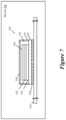
- FIG. 7 illustrates a device that uses a 3D IC of some embodiments of the invention.
- Some embodiments provide a three-dimensional (3D) circuit that has multiple stacked IC dies, with a memory circuit that spans two or more of the stacked IC dies.
- the memory circuit includes a memory block on one die and data lines for the memory block on another IC die.
- the 3D circuit includes a first IC die with a first set of two or more memory blocks that have a first set of data lines.
- the 3D circuit also includes a second IC die that is stacked with the first IC die and that includes a second set of two or more memory blocks with a second set of data lines.
- the 3D circuit further includes a third IC die that is stacked with the first and second IC dies and that includes a third set of data lines, which connect through several z-axis connections with the first and second sets of data lines to carry data to and from the first and second memory block sets when data is being written to, and read from, the first and second memory block sets.
- the first and second memory block sets form a single addressable memory circuit, while in other embodiments these memory block sets are part of multiple, separately addressable memory circuits (e.g., the first memory block set is part of a first addressable memory circuit, while the second memory block set is part of a different, second addressable memory circuit).
- Examples of such memory circuits include DRAMs (Dynamic Random Access Memories), SRAMs (Static Random Access Memories), ROMs (Read Only Memories), etc.
- the set of one or more memory circuits formed by the first and second memory block sets in some embodiments include (1) a set of addressing circuits to activate different addressed locations in the memory blocks, and (2) a set of input/output (I/O) circuits to write/read data to addressed locations in the memory blocks.
- the addressing circuits are implemented at least partially on the first and second dies, while the I/O circuits are implemented at least partially on the third die.
- the addressing circuits include sense amplifiers defined on the first and second dies, while the I/O circuits include the third data line sets on the third die, which connect to the first and second data line sets.
- the I/O circuit set further includes a set of buffers defined on the third die.
- buffers are used in different embodiments. Examples of such buffers include inverters, level shifters, stateful storage circuits (e.g., latches, flip flops, etc.), etc.
- connections that cross bonding layers (that bond vertically stacked dies) to electrically connect electrical nodes (e.g., circuit points, etc.) on different dies are referred to below as z-axis connections. This is because these connections traverse completely or mostly in the z-axis of the 3D circuit (e.g., because these connections in some embodiments cross the bonding layer(s) in a direction normal or nearly normal to the bonded surface), with the x-y axes of the 3D circuit defining the planar surface of the IC die substrate or interconnect layers. These connections are also referred to as vertical connections to differentiate them from the horizontal planar connections along the interconnect layers of the IC dies.
- z-axis connections are native interconnects that allow signals to span two different dies with no standard interfaces and no input/output protocols at the cross-die boundaries.
- the direct bonded interconnects allow native signals from one die to pass directly to the other die with no modification of the native signal or negligible modification of the native signal, thereby forgoing standard interfacing and consortium-imposed input/output protocols.
- z-axis connections are direct unbuffered electrical connections (i.e., connections that do not go through any buffer or other circuit).
- a z-axis connection between two dies terminates typically on electrical contacts (referred to as pads) on each die (e.g., on an interconnect or substrate layer of each die).
- pads electrical contacts
- the z-axis connection pad on each die electrically connects the z-axis connection with circuit nodes on the die that need to provide the signal to the z-axis connection or to receive the signal from the z-axis connection.
- a z-axis connection pad connects to an interconnect segment on an interconnect layer of a die, which then carries the signal to a circuit block on the die's substrate through a series of vias and interconnect lines.
- Vias are z-axis structures on each die that carry signals between the interconnect layers of the die, and between the IC die substrate and the interconnect layers of the die.
- FIG. 1 illustrates a 3D circuit 100 of some embodiments of the invention.
- the 3D circuit 100 has a memory circuit 105 with different components on different IC dies.
- the 3D circuit 100 includes four dies 120 - 126 that are vertically stacked on top of each other. To vertically stack these dies on top of each other, some embodiments use commonly known techniques for aligning dies vertically and bonding neighboring dies through a bonding layer. As further described below, some embodiments use z-axis connections 160 (e.g., connections that are orthogonal to the x-y surface of the dies) to electrically connect nodes on vertically mounted dies.
- z-axis connections 160 e.g., connections that are orthogonal to the x-y surface of the dies
- the first IC die 120 includes a first set of four memory blocks 130
- the second IC die 122 includes a second set of four memory blocks 132
- the third IC die 124 includes a third set of four memory blocks 134 .
- the memory blocks in each of these three dies 120 - 124 are arranged in a single direction (e.g., a single row or single column), with the cross section of each block (e.g., block 130 d on die 120 ) on each die overlapping the cross section of two other memory blocks on two other dies (e.g., blocks 132 d and 134 d on dies 122 and 124 ).
- each memory block on one die is vertically aligned with two other memory blocks on two other dies in this example.
- the memory blocks are not so aligned, and/or have a different arrangement on each die (e.g., are arranged in a two-dimensional array).
- each die includes a semiconductor substrate 190 and a set of interconnect layers 192 defined above the semiconductor substrate.
- numerous electronic components e.g., active components, like transistors and diodes, or passive components, like resistors and capacitors
- interconnect wiring on the die's set of interconnect layers in order to form storage cells, microcircuits (e.g., Boolean gates, such as AND gates, OR gates, etc.) and/or larger circuit blocks (e.g., functional blocks, such as memories, decoders, logic units, multipliers, adders, etc.).
- each memory block on each die is defined on that die's semiconductor substrate with the needed interconnect wiring on the die's set of interconnect layers.
- Each memory block has a set of local data lines 140 on the same IC die as the memory block.
- the local data lines 140 of each memory block carry data read from, and written to, the memory block.
- These local data lines 140 of each memory block connect to global data lines 145 on the fourth IC die 126 through control circuits 165 and z-axis connections 160 .
- the memory circuit has several sets of global data lines 145 on the fourth IC die 126 , with each set of global data lines used by a different set of overlapping memory blocks on the first, second and third IC dies 120 - 124 .
- the global data lines 145 include wiring that is defined on one or more interconnect layers of the fourth IC die 126 .
- the global data lines 145 provide the data read from the memory blocks to the I/O circuits 180 (e.g., circuits on the fourth IC die 126 ) of the memory circuit 105 , and provide data to write to the memory blocks from the I/O circuits 180 .
- the I/O circuits 180 are implemented at least partially on the fourth die 126 .
- the I/O circuits in some embodiments include buffer circuits (e.g., inverters, level shifters, stateful storage circuits (e.g., latches, flip flops, etc.), etc.) that are defined on the fourth IC die 126 .
- buffer circuits e.g., inverters, level shifters, stateful storage circuits (e.g., latches, flip flops, etc.), etc.
- the z-axis connections 160 in some embodiments electrically connect circuit nodes in overlapping portions of the local data lines 140 and global data lines 145 , in order to carry data between the global data lines and the local data lines. These z-axis connections between the dies are very short as the dies are very thin. For instance, in some embodiments, the z-axis connections are less than 10 or 20 microns.
- the z-axis connections are through silicon vias (TSVs) in some embodiments.
- the memory circuit 105 has row and column addressing circuits 170 and 172 that activate a set of addressed locations in a set of memory blocks based on addresses that the receive from other circuits of the 3D circuit 100 .
- the memory circuit 105 has different row and column addressing sub-circuits for each memory block that process the received addresses for that memory block.
- each memory block's row and column addressing sub-circuits are at least partially defined on that block's die.
- the addressing sub-circuits of each memory block in some embodiments include sense amplifiers and bit lines that are defined on the memory block's die.
- the bit lines of the memory block connect the block's storage cells to their respective block's local data lines through sense amplifiers that amplify the values stored in the storage cells.
- FIG. 2 illustrates another perspective view of the memory blocks 130 - 134 , the local data lines 140 and global data lines 145 of the memory circuit 105 .
- the memory circuit 105 is a DRAM that is implemented with a differential logic design.
- This view illustrates the four memory blocks on each of the first three dies 120 - 124 , with each memory block vertically overlapping two other memory blocks on two other dies and each set of three vertically overlapping memory blocks on the three dies 120 - 124 sharing one set of global data lines 145 .
- it shows the local data lines 140 of each memory block connected through pass gate controls 265 (serving as the control circuits 165 ) and z-axis connections 160 to the global data lines 145 .
- Each memory block's set of local data lines 140 has two subsets of complementary local data lines (as the design is a differential design), with each subset having several (e.g., 8, 16, 32, 64, etc.) data lines.
- each pass gate control 265 of the memory block has two subset of pass gates for the two subsets of local data lines, with each subset of pass gates having several (e.g., 8, 16, 32, 64, etc.) pass gates.
- the pass gate controls 265 receive die select signals that at any given time, activate the pass gate controls for the memory blocks of just one die. For example, for one set of address values, the pass gate controls 265 of the first IC die 120 would receive an active die select signals DS 1 that would turn on their transistors to connect their local data lines 140 to the global data lines 145 , while the other pass gate controls 265 of the other IC dies 122 and 124 would not receive active die select signals DS 2 and DS 3 .
- a given address in these embodiments would cause each of the memory blocks on one IC die (e.g., the first IC die) to read from or write to one set of storage locations.
- a large amount of data can be read from, or written to, addressed sets of locations in the memory blocks on one IC die (e.g., the first IC die) concurrently through the local data lines 140 of the memory blocks, their associated pass gate controls 265 , and the different sets of global data lines 145 .
- the access to any one memory block on a die is not blocked by the concurrent access of another memory block on the die as the different memory blocks on the same die connect to different global data lines.
- the global data lines do not have to span all the memory blocks on a given die, and hence have a shorter length than global data lines that are typically used today to span a row or column of memory blocks on a single die.
- the span of the global data lines is one length, or less than one length, of a memory block, as each set of global data lines is used for three overlapping memory blocks that have the same footprint (i.e., cross section). Hence, each set of global data lines needs to be long enough to provide sufficient space for connecting to the z-axis connections from the memory blocks.
- the short span of the global data lines is highly advantageous when the memory circuit has a large number of memory blocks (e.g., 8, 16, etc.).
- the length of the wire and z-axis connections between each memory block's local data lines 140 and its corresponding global data lines 145 is rather short, as the global data lines traverse over the local data lines very near to the memory blocks, and the z-axis connections are very short.
- the memory circuit 105 sequentially activates the die select signals of the different dies so that after concurrently reading from or writing to addressed locations in all the memory blocks of one die, the memory circuit can then read from or write to the addressed locations of the memory block of other die(s). For instance, in the above-described example, after reading from or writing to the set of address locations in the memory blocks of the first IC die 120 , the memory circuit sequentially provides active die select signals to the pass gate controls of the second and third IC dies 122 and 124 so that it can sequentially read from or write to the set of address locations in the memory blocks of the second IC die 122 followed by the set of address locations in the memory blocks of the third IC dies 124 . In other embodiments, the memory circuit 105 has other schemes for activating the pass gate controls and accessing the memory blocks on different IC dies, as further described below by reference to FIG. 4 .
- FIG. 3 illustrates the structure of a DRAM memory block 300 that can be used to implement the memory blocks 130 , 132 and 134 when the memory circuit is a DRAM.
- the memory block 300 has a commonly used differential design that is used in many DRAMs today.
- each logical storage cell is implemented by a complementary pair of single physical storage cells 310 (e.g., single capacitors) that are accessed through complementary pass gate transistors 315 , word lines and bit lines.
- Each cell's pass gate transistor connects to a bit line, a word line and the cell.
- the bit and word lines 330 and 332 that connect to the cell's pass gate transistor are complimentary (i.e., carry the opposite signal values) to the bit and word lines that connect to that cell's complimentary cell.
- each particular pass gate transistor 315 of each particular cell has its gate connected to a particular word line, while a word line that is complementary to the particular word line connects to the gate of the pass gate transistor of a cell that is the complementary cell to the particular cell.
- each particular pass gate transistor 315 of each particular cell has one of its second terminal connected to a particular bit line, while a bit line that is complementary to the particular bit line connects to the second terminal of the pass gate transistor of the complementary cell of the particular cell.
- each pass gate transistor's third terminal connects to its storage cell.
- Each pair of complementary bit lines are fed to a differential sense amplifier circuit 340 that amplifies the differential voltage value read from a complementary pair of cells by the bit lines, in order to quickly move the data to the high and low rail values.
- each differential pair of cells has one cell store a high or low value, while the other stores the opposite value or a mid-range value.
- the sense amplifiers quickly move the data values to the desired rail values to address any degradation in stored values, or to address the storage of the mid-range value.
- the sense amplifier circuits 340 includes several differential sense amplifiers (e.g., one for each bit line pair, or one for each several bit lines pairs).
- each differential sense amplifier is formed as a gated, cross coupled latch.
- the bit lines in some embodiments connect to the local data lines 140 of the memory circuit through column addressing controls (not shown) of the column addressing circuit of the memory circuit.
- all the components illustrated in FIG. 3 i.e., the bit and word lines 330 and 332 , the local data lines 140 , the storage cells 310 , the pass gate transistors 315 , the sense amplifier circuits 340 ) in some embodiments are defined entirely on one of the dies 120 , 122 or 124 .
- FIG. 4 illustrates an example where the pass gate transistors 465 of a memory block 400 (e.g., memory block 130 , 132 or 134 ) are controlled by AND'ing a die select signal and a block select signal.
- the 3D memory circuit 105 can have any arbitrary combination of non-overlapping memory blocks connect their local data lines 140 to the global data lines 145 through the pass gate transistors 265 and the z-axis connections 160 . For instance, for the example illustrated in FIG.
- a particular combination of die and block select signals can result in the memory bocks 130 a , 132 b , and 134 c outputting their results concurrently on their respective global data lines 145 .
- other embodiments use staggered sets of sense amplifiers such that consecutive bit lines in each set of bits lines are fed to different sense amplifiers (e.g., even complementary bit lines are fed to a sense amplifier to the right of the memory cells while odd complementary bit lines are fed to a sense amplifier to the left of the memory cells).
- FIG. 5 illustrates buffer circuits 500 of the I/O circuits 180 defined on the fourth IC die 126 along with the global data lines 145 .
- buffers include inverters 502 , level shifters 504 , stateful storage circuits 506 (e.g., latches, flip flops, etc.), etc.
- I/O circuits 180 of the memory circuit 105 receives data to store in the memory blocks from, and supply data read from the memory blocks to, circuit defined on the first, second, third and fourth dies IC 120 - 126 .
- these circuits include compute circuits 550 defined on the fourth IC die 126 , as shown in FIG. 5 .
- these compute circuits on the fourth IC die 126 are processing cores that implement machine-trained nodes (e.g., neurons) of a machine trained network (e.g., a neural network), while the memory blocks store values used or computed by these compute circuits (e.g., weight values or activation values).
- machine-trained nodes e.g., neurons
- a machine trained network e.g., a neural network
- FIG. 1 For instance, some embodiments have two sets of global data lines 145 for two opposing sides (e.g., right and left sets of global data lines) of each set of stacked memory blocks (e.g., memory blocks 130 a , 132 a , and 134 a ), instead of just having one set of global data lines 145 for each set of stacked memory blocks. Also, some embodiments also employ a multiplexer between the I/O circuit 500 and the compute circuits 550 to connect different subsets of global data lines with the compute circuits at different times. Both these approaches would increase the number of memory blocks that can be concurrently or sequentially accessed through the global data lines and the z-axis connections.
- FIG. 1 For instance, some embodiments have two sets of global data lines 145 for two opposing sides (e.g., right and left sets of global data lines) of each set of stacked memory blocks (e.g., memory blocks 130 a , 132 a , and 134 a ), instead of just having one set of global
- the memory blocks on one set of stacked IC dies that use the global data lines on another stacked IC die are part of two or more separately addressable memory circuits, instead of the single addressable memory circuit 105 .
- other embodiments use many more memory blocks and global data lines than the memory circuit 105 .
- the memory circuit of other embodiments has eight overlapping memory blocks on three dies.
- the memory circuit has eight memory blocks on each of the three stacked dies 120 , 122 and 124 , and these twenty-four memory blocks form eight sets of three overlapping memory blocks on these dies. Each of these eight sets shares two sets of global data lines that connect to two sets of local data lines that emanate from two sides of each memory block.
- other embodiments have different sets of global data lines on different stacked IC dies (e.g., a first set of global data lines on IC die 126 for use by a first set of memory blocks on IC dies 120 - 124 , and a second set of global data lines on IC die 120 for use by a second set of memory blocks on IC dies 122 - 126 ).
- the four dies 120 - 126 of the 3D circuit 100 of FIG. 1 are face-to-back mounted, in that the set of interconnect layers of one die is mounted next to the backside of the semiconductor substrate of the other die.
- TSVs are used as the z-axis connections to carry signals from one die to another.
- the 3D circuit of other embodiments uses other techniques for vertically stacking the dies.
- FIG. 6 illustrates one such alternative approach. It shows a 3D circuit 600 that, like the 3D circuit 100 , has four vertically stacked dies, with the first three being face-to-back mounted. However, unlike the 3D circuit 100 , the third and fourth dies 124 and 626 of the 3D circuit 600 are face-to-face stacked. In some embodiments, the die 626 is similar to the die 126 in that it includes the global data lines 145 discussed above. However, the die 626 in some embodiments has contacts that facilitate its face-to-face mounting to the die 124 .
- the sets of interconnect layers of the dies 124 and 626 are facing each other and are bonded to each other through a direct bonding process that establishes direct-contact metal-to-metal bonding, oxide bonding, or fusion bonding between these two sets of interconnect layers.
- An example of such bonding is copper-to-copper (Cu—Cu) metallic bonding between two copper conductors in direct contact.
- the direct bonding is provided by a hybrid bonding technique such as DBI® (direct bond interconnect) technology, and other metal bonding techniques (such as those offered by Invensas Bonding Technologies, Inc., an Xperi Corporation company, San Jose, Calif.).
- DBI connects span across silicon oxide and silicon nitride surfaces.
- the DBI process is further described in U.S. Pat. Nos. 6,962,835 and 7,485,968, both of which are incorporated herein by reference. This process is also described in U.S. Published Patent Application 2018/0102251, which is also incorporated herein by reference.
- the back side of the fourth die 626 can be used to connect to a ball grid array, which is then used to mount the 3D circuit 600 on a board.
- the back side of the fourth die 626 can be used to connect to a ball grid array, which is then used to mount the 3D circuit 600 on a board.
- face-to-face mount two pairs of dies e.g., dies 120 and 122 and dies 124 and 626
- back-to-back mount one die from each of these pairs e.g., dies 122 and 124 .
- Back-to-back stacked dies have the backside of the semiconductor substrate of one die mounted next to the backside of the semiconductor substrate of the other die.
- FIG. 7 illustrates a device 702 that uses a 3D IC 100 .
- the 3D IC die 100 includes a cap 750 that encapsulates the four dies of this IC in a secure housing 725 .
- On the back side of the die 120 one or more TSVs and/or interconnect layers are defined to connect the 3D IC to a ball grid array 720 (e.g., a micro bump array) that allows this to be mounted on a printed circuit board 730 of the device 702 .
- the device 702 includes other components (not shown). In some embodiments, examples of such components include one or more memory storages (e.g., semiconductor or disk storages), input/output interface circuit(s), one or more processors, etc.
- the die 120 receives data signals through the ball grid array, and routes the received signals to I/O circuits on this and/or other dies through interconnect lines on the interconnect layer, vias between the interconnect layers, and z-axis connections with the other dies. As mentioned by reference to FIG. 6 , other embodiments connect the backside of the substrate of the die 626 to the ball grid array.
Landscapes
- Engineering & Computer Science (AREA)
- Theoretical Computer Science (AREA)
- Microelectronics & Electronic Packaging (AREA)
- Human Computer Interaction (AREA)
- Physics & Mathematics (AREA)
- General Engineering & Computer Science (AREA)
- General Physics & Mathematics (AREA)
- Computer Hardware Design (AREA)
- Dram (AREA)
Abstract
Description
Claims (14)
Priority Applications (3)
| Application Number | Priority Date | Filing Date | Title |
|---|---|---|---|
| US17/098,299 US11599299B2 (en) | 2019-11-19 | 2020-11-13 | 3D memory circuit |
| US18/100,110 US12293108B2 (en) | 2019-11-19 | 2023-01-23 | 3D memory circuit |
| US19/172,520 US20250328278A1 (en) | 2019-11-19 | 2025-04-07 | 3d memory circuit |
Applications Claiming Priority (2)
| Application Number | Priority Date | Filing Date | Title |
|---|---|---|---|
| US201962937749P | 2019-11-19 | 2019-11-19 | |
| US17/098,299 US11599299B2 (en) | 2019-11-19 | 2020-11-13 | 3D memory circuit |
Related Child Applications (1)
| Application Number | Title | Priority Date | Filing Date |
|---|---|---|---|
| US18/100,110 Continuation US12293108B2 (en) | 2019-11-19 | 2023-01-23 | 3D memory circuit |
Publications (2)
| Publication Number | Publication Date |
|---|---|
| US20210149586A1 US20210149586A1 (en) | 2021-05-20 |
| US11599299B2 true US11599299B2 (en) | 2023-03-07 |
Family
ID=75909965
Family Applications (3)
| Application Number | Title | Priority Date | Filing Date |
|---|---|---|---|
| US17/098,299 Active 2041-02-12 US11599299B2 (en) | 2019-11-19 | 2020-11-13 | 3D memory circuit |
| US18/100,110 Active US12293108B2 (en) | 2019-11-19 | 2023-01-23 | 3D memory circuit |
| US19/172,520 Pending US20250328278A1 (en) | 2019-11-19 | 2025-04-07 | 3d memory circuit |
Family Applications After (2)
| Application Number | Title | Priority Date | Filing Date |
|---|---|---|---|
| US18/100,110 Active US12293108B2 (en) | 2019-11-19 | 2023-01-23 | 3D memory circuit |
| US19/172,520 Pending US20250328278A1 (en) | 2019-11-19 | 2025-04-07 | 3d memory circuit |
Country Status (1)
| Country | Link |
|---|---|
| US (3) | US11599299B2 (en) |
Cited By (2)
| Publication number | Priority date | Publication date | Assignee | Title |
|---|---|---|---|---|
| US20230317561A1 (en) * | 2022-03-30 | 2023-10-05 | Intel Corporation | Scalable architecture for multi-die semiconductor packages |
| US12293108B2 (en) | 2019-11-19 | 2025-05-06 | Adeia Semiconductor Technologies Llc | 3D memory circuit |
Families Citing this family (3)
| Publication number | Priority date | Publication date | Assignee | Title |
|---|---|---|---|---|
| EP4165637A4 (en) * | 2020-06-16 | 2024-07-10 | Groq, Inc. | DETERMINISTIC NEAR-COMPUTATIONAL MEMORY FOR DETERMINISTIC PROCESSOR AND ENHANCED DATA MOVEMENT BETWEEN STORAGE UNITS AND PROCESSING UNITS |
| US20230207428A1 (en) * | 2021-12-23 | 2023-06-29 | Intel Corporation | Integrated circuit die for efficient incorporation in a die stack |
| US20240088099A1 (en) * | 2022-09-09 | 2024-03-14 | Advanced Micro Devices, Inc. | 3d layout and organization for enhancement of modern memory systems |
Citations (144)
| Publication number | Priority date | Publication date | Assignee | Title |
|---|---|---|---|---|
| US5016138A (en) | 1987-10-27 | 1991-05-14 | Woodman John K | Three dimensional integrated circuit package |
| US5376825A (en) | 1990-10-22 | 1994-12-27 | Seiko Epson Corporation | Integrated circuit package for flexible computer system alternative architectures |
| US5579207A (en) | 1994-10-20 | 1996-11-26 | Hughes Electronics | Three-dimensional integrated circuit stacking |
| US5621863A (en) | 1994-07-28 | 1997-04-15 | International Business Machines Corporation | Neuron circuit |
| US5673478A (en) | 1995-04-28 | 1997-10-07 | Texas Instruments Incorporated | Method of forming an electronic device having I/O reroute |
| US5717832A (en) | 1994-07-28 | 1998-02-10 | International Business Machines Corporation | Neural semiconductor chip and neural networks incorporated therein |
| US5740326A (en) | 1994-07-28 | 1998-04-14 | International Business Machines Corporation | Circuit for searching/sorting data in neural networks |
| US5793115A (en) | 1993-09-30 | 1998-08-11 | Kopin Corporation | Three dimensional processor using transferred thin film circuits |
| US5909587A (en) | 1997-10-24 | 1999-06-01 | Advanced Micro Devices, Inc. | Multi-chip superscalar microprocessor module |
| US20010017418A1 (en) | 1999-12-22 | 2001-08-30 | Kabushiki Kaisha Toshiba | Semiconductor device |
| US6320255B1 (en) | 1998-10-09 | 2001-11-20 | Texas Instruments Incorporated | Rerouted semiconductor device and method of fabrication |
| US6421654B1 (en) | 1996-11-18 | 2002-07-16 | Commissariat A L'energie Atomique | Learning method generating small size neurons for data classification |
| US20030227795A1 (en) * | 2002-06-11 | 2003-12-11 | Mirmajid Seyyedy | Hybrid MRAM array structure and operation |
| US6707124B2 (en) | 1992-10-26 | 2004-03-16 | Texas Instruments Incorporated | HID land grid array packaged device having electrical and optical interconnects |
| US6844624B1 (en) | 2003-06-26 | 2005-01-18 | Renesas Technology Corp. | Multichip module |
| US6891447B2 (en) | 2002-07-12 | 2005-05-10 | Massachusetts Institute Of Technology | Electromagnetic coupling connector for three-dimensional electronic circuits |
| US20050127490A1 (en) | 2003-12-16 | 2005-06-16 | Black Bryan P. | Multi-die processor |
| US6909194B2 (en) | 1999-08-27 | 2005-06-21 | Micron Technology, Inc. | Electronic assembly having semiconductor component with polymer support member and method of fabrication |
| US6917219B2 (en) | 2003-03-12 | 2005-07-12 | Xilinx, Inc. | Multi-chip programmable logic device having configurable logic circuitry and configuration data storage on different dice |
| US6962835B2 (en) | 2003-02-07 | 2005-11-08 | Ziptronix, Inc. | Method for room temperature metal direct bonding |
| US20060036559A1 (en) | 2002-03-12 | 2006-02-16 | Alex Nugent | Training of a physical neural network |
| US7046522B2 (en) | 2002-03-21 | 2006-05-16 | Raymond Jit-Hung Sung | Method for scalable architectures in stackable three-dimensional integrated circuits and electronics |
| US7099215B1 (en) | 2005-02-11 | 2006-08-29 | North Carolina State University | Systems, methods and devices for providing variable-latency write operations in memory devices |
| US7124250B2 (en) | 2003-01-03 | 2006-10-17 | Samsung Electronics Co., Ltd. | Memory module device for use in high-frequency operation |
| US7202566B2 (en) | 2003-12-05 | 2007-04-10 | Taiwan Semiconductor Manufacturing Company, Ltd. | Crossed power strapped layout for full CMOS circuit design |
| US20070220207A1 (en) | 2006-03-14 | 2007-09-20 | Bryan Black | Transferring data from stacked memory |
| US20080080261A1 (en) * | 2005-09-26 | 2008-04-03 | Rambus Inc. | Memory system topologies including a buffer device and an integrated circuit memory device |
| US7485968B2 (en) | 2005-08-11 | 2009-02-03 | Ziptronix, Inc. | 3D IC method and device |
| US20090070727A1 (en) | 2007-09-12 | 2009-03-12 | Solomon Research Llc | Three dimensional integrated circuits and methods of fabrication |
| SG153683A1 (en) | 2007-12-14 | 2009-07-29 | Tezzaron Semiconductor S Pte L | 3d integrated circuit package and method of fabrication thereof |
| US7638869B2 (en) | 2007-03-28 | 2009-12-29 | Qimonda Ag | Semiconductor device |
| US7692946B2 (en) | 2007-06-29 | 2010-04-06 | Intel Corporation | Memory array on more than one die |
| US20100085825A1 (en) * | 2008-10-07 | 2010-04-08 | Micron Technology, Inc. | Stacked device remapping and repair |
| US20100140750A1 (en) | 2008-12-10 | 2010-06-10 | Qualcomm Incorporated | Parallel Plane Memory and Processor Coupling in a 3-D Micro-Architectural System |
| US20100195364A1 (en) * | 2009-02-05 | 2010-08-05 | Elpida Memory, Inc. | Semiconductor device |
| US7863918B2 (en) | 2007-11-13 | 2011-01-04 | International Business Machines Corporation | Disposable built-in self-test devices, systems and methods for testing three dimensional integrated circuits |
| US20110121433A1 (en) * | 2009-11-20 | 2011-05-26 | Hynix Semiconductor Inc. | Semiconductor chip and stacked semiconductor package having the same |
| US20110184688A1 (en) * | 2010-01-28 | 2011-07-28 | Elpida Memory, Inc. | Semiconductor device, test method thereof, and system |
| US20110208906A1 (en) * | 2010-02-25 | 2011-08-25 | Peter Gillingham | Semiconductor memory device with plural memory die and controller die |
| US8032711B2 (en) | 2006-12-22 | 2011-10-04 | Intel Corporation | Prefetching from dynamic random access memory to a static random access memory |
| US8042082B2 (en) | 2007-09-12 | 2011-10-18 | Neal Solomon | Three dimensional memory in a system on a chip |
| US8110899B2 (en) | 2006-12-20 | 2012-02-07 | Intel Corporation | Method for incorporating existing silicon die into 3D integrated stack |
| US8148814B2 (en) | 2009-02-10 | 2012-04-03 | Hitachi, Ltd. | Semiconductor integrated circuit device comprising a plurality of semiconductor chips mounted to stack for transmitting a signal between the semiconductor chips |
| US20120201068A1 (en) | 2009-10-23 | 2012-08-09 | Ware Frederick A | Stacked semiconductor device |
| US20120243355A1 (en) * | 2011-03-24 | 2012-09-27 | Hynix Semiconductor Inc. | Semiconductor apparatus |
| US20120242346A1 (en) | 2011-03-22 | 2012-09-27 | Taiwan Semiconductor Manufacturing Company, Ltd. | Power Compensation in 3DIC Testing |
| US20120250286A1 (en) * | 2011-03-31 | 2012-10-04 | Taiwan Semiconductor Manufacturing Company, Ltd. | Apparatus and Method for Increasing Bandwidths of Stacked Dies |
| US20130032950A1 (en) | 2010-04-26 | 2013-02-07 | Rambus Inc. | Techniques for Interconnecting Stacked Dies Using Connection Sites |
| US20130051116A1 (en) | 2011-08-24 | 2013-02-28 | Advanced Micro Devices, Inc. | Integrated circuit with face-to-face bonded passive variable resistance memory and method for making the same |
| US8432467B2 (en) | 2009-07-24 | 2013-04-30 | Raytheon Company | Integrated detection and display imaging system and method |
| US20130144542A1 (en) | 2010-06-07 | 2013-06-06 | California Institute Of Technology | Analysis device including a mems and/or nems network |
| US20130187292A1 (en) | 2012-01-20 | 2013-07-25 | Taiwan Semiconductor Manufacturing Company, Ltd. | Multi-Dimensional Integrated Circuit Structures and Methods of Forming the Same |
| US20130207268A1 (en) | 2012-02-14 | 2013-08-15 | Stmicroelectronics (Crolles 2) Sas | Chip assembly system |
| US8516409B2 (en) | 2010-11-11 | 2013-08-20 | International Business Machines Corporation | Implementing vertical die stacking to distribute logical function over multiple dies in through-silicon-via stacked semiconductor device |
| US20130242500A1 (en) | 2009-03-30 | 2013-09-19 | Megica Corporation | Integrated circuit chip using top post-passivation technology and bottom structure technology |
| US8547769B2 (en) | 2011-03-31 | 2013-10-01 | Intel Corporation | Energy efficient power distribution for 3D integrated circuit stack |
| US8546955B1 (en) | 2012-08-16 | 2013-10-01 | Xilinx, Inc. | Multi-die stack package |
| US20130275823A1 (en) | 2011-04-06 | 2013-10-17 | International Business Machines Corporation | Programmable logic circuit using three-dimensional stacking techniques |
| US20130275798A1 (en) * | 2009-10-09 | 2013-10-17 | Elpida Memory, Inc. | Semiconductor device, control method for the semiconductor device and information processing system including the same |
| US20140022002A1 (en) | 2012-07-20 | 2014-01-23 | Qualcomm Incorporated | Thermal management of tightly integrated semiconductor device, system and/or package |
| US20140040698A1 (en) * | 2012-08-06 | 2014-02-06 | Advanced Micro Devices, Inc. | Stacked memory device with metadata mangement |
| US8704384B2 (en) | 2012-02-17 | 2014-04-22 | Xilinx, Inc. | Stacked die assembly |
| US20140133246A1 (en) * | 2012-11-09 | 2014-05-15 | Xilinx, Inc. | Configurable embedded memory system |
| US8736068B2 (en) | 2010-10-26 | 2014-05-27 | International Business Machines Corporation | Hybrid bonding techniques for multi-layer semiconductor stacks |
| TWI441308B (en) | 2006-01-13 | 2014-06-11 | 特瑟榮半導體(新加坡)私人有限公司 | Stacked wafer for 3D integration |
| US20140189257A1 (en) * | 2013-01-02 | 2014-07-03 | SK Hynix Inc. | Semiconductor memory device |
| US8797818B2 (en) | 2008-12-30 | 2014-08-05 | Micron Technology, Inc. | Variable memory refresh devices and methods |
| US8816506B2 (en) | 2008-12-19 | 2014-08-26 | Tessera Advanced Technologies, Inc. | Semiconductor device and method of manufacturing the same |
| US20140323046A1 (en) | 2012-09-18 | 2014-10-30 | Panasonic Corporation | Antenna, transmitter device, receiver device, three-dimensional integrated circuit, and contactless communication system |
| US8901749B2 (en) | 2009-04-27 | 2014-12-02 | Samsung Electronics Co., Ltd. | Semiconductor packages and electronic systems including the same |
| US8907439B1 (en) | 2010-08-30 | 2014-12-09 | Sandia Corporation | Focal plane array with modular pixel array components for scalability |
| US8930647B1 (en) | 2011-04-06 | 2015-01-06 | P4tents1, LLC | Multiple class memory systems |
| US20150016172A1 (en) * | 2013-07-15 | 2015-01-15 | Advanced Micro Devices, Inc. | Query operations for stacked-die memory device |
| US8947931B1 (en) | 2014-06-13 | 2015-02-03 | Sandisk Technologies Inc. | Memory module |
| US20150121052A1 (en) * | 2013-10-24 | 2015-04-30 | International Business Machines Corporation | Three-dimensional processing system having independent calibration and statistical collection layer |
| US9067272B2 (en) | 2010-06-18 | 2015-06-30 | Arizona Board Of Regents On Behalf Of Arizona State University | Systems and methods for high aspect ratio flip-chip interconnects |
| US20150213860A1 (en) * | 2014-01-28 | 2015-07-30 | Micron Technology, Inc. | Semiconductor device including spiral data path |
| US20150228584A1 (en) | 2014-02-13 | 2015-08-13 | Taiwan Semiconductor Manufacturing Company, Ltd. | Multi-via interconnect structure and method of manufacture |
| US20150355763A1 (en) * | 2014-03-07 | 2015-12-10 | Semiconductor Energy Laboratory Co., Ltd. | Sensor, input device, and input/output device |
| US20160111386A1 (en) | 2014-10-16 | 2016-04-21 | Globalfoundries Inc. | Bond pad structure for low temperature flip chip bonding |
| US20160181214A1 (en) * | 2014-12-22 | 2016-06-23 | Ki-Seok OH | Stacked memory chip having reduced input-output load, memory module and memory system including the same |
| US20160225431A1 (en) | 2006-12-14 | 2016-08-04 | Rambus Inc. | Multi-die memory device |
| US20160233134A1 (en) | 2015-02-09 | 2016-08-11 | Qualcomm Incorporated | Clock tree synthesis for low cost pre-bond testing of 3d integrated circuits |
| US9432298B1 (en) | 2011-12-09 | 2016-08-30 | P4tents1, LLC | System, method, and computer program product for improving memory systems |
| US9478496B1 (en) | 2015-10-26 | 2016-10-25 | United Microelectronics Corp. | Wafer to wafer structure and method of fabricating the same |
| US20160329312A1 (en) | 2015-05-05 | 2016-11-10 | Sean M. O'Mullan | Semiconductor chip with offloaded logic |
| US9497854B2 (en) | 2011-10-18 | 2016-11-15 | Arctic Sand Technologies, Inc. | Multi-layer power converter with devices having reduced lateral current |
| US9501603B2 (en) | 2014-09-05 | 2016-11-22 | International Business Machines Corporation | Integrated circuit design changes using through-silicon vias |
| US20160379115A1 (en) | 2015-06-29 | 2016-12-29 | Microsoft Technology Licensing, Llc | Deep neural network processing on hardware accelerators with stacked memory |
| US20170092615A1 (en) | 2015-06-02 | 2017-03-30 | Noda Screen Co., Ltd. | Semiconductor memory device |
| US20170092616A1 (en) | 2015-09-25 | 2017-03-30 | Michael Z. Su | Semiconductor workpiece with selective backside metallization |
| US9640233B2 (en) | 2012-02-28 | 2017-05-02 | Samsung Electronics Co., Ltd. | Semiconductor memory device having inverting circuit and controlling method there of |
| US9647187B1 (en) | 2013-05-30 | 2017-05-09 | Hrl Laboratories, Llc | Multi-slice two-dimensional phased array assembly |
| US9645603B1 (en) | 2013-09-12 | 2017-05-09 | Advanced Processor Architectures, Llc | System clock distribution in a distributed computing environment |
| US20170148737A1 (en) | 2015-11-19 | 2017-05-25 | Globalfoundries Inc. | Method and structure for establishing interconnects in packages using thin interposers |
| US20170154655A1 (en) * | 2015-11-26 | 2017-06-01 | Samsung Electronics Co., Ltd. | Stacked memory devices, and memory packages and memory systems having the same |
| US20170194038A1 (en) * | 2015-12-30 | 2017-07-06 | SK Hynix Inc. | Latch circuit and semiconductor apparatus including the same |
| US20170213787A1 (en) | 2016-01-27 | 2017-07-27 | Michael S. Alfano | Interposer with beyond reticle field conductor pads |
| US9726691B2 (en) | 2014-01-07 | 2017-08-08 | International Business Machines Corporation | 3D chip testing through micro-C4 interface |
| WO2017138121A1 (en) | 2016-02-10 | 2017-08-17 | ルネサスエレクトロニクス株式会社 | Semiconductor device |
| US9746517B2 (en) | 2011-02-07 | 2017-08-29 | Texas Instruments Incorporated | IC interposer with TAP controller and output boundary scan cell |
| US20170278789A1 (en) | 2014-03-20 | 2017-09-28 | Taiwan Semiconductor Manufacturing Company, Ltd. | Method for layout design and structure with inter-layer vias |
| US20170278213A1 (en) | 2016-03-24 | 2017-09-28 | Advanced Micro Devices, Inc. | Hierarchical register file at a graphics processing unit |
| US20170285584A1 (en) | 2016-04-04 | 2017-10-05 | Fanuc Corporation | Machine learning device that performs learning using simulation result, machine system, manufacturing system, and machine learning method |
| US20170301625A1 (en) | 2013-12-18 | 2017-10-19 | Intel Corporation | Integrated circuit package with embedded bridge |
| US9853053B2 (en) * | 2012-09-10 | 2017-12-26 | 3B Technologies, Inc. | Three dimension integrated circuits employing thin film transistors |
| US20180005697A1 (en) * | 2016-06-29 | 2018-01-04 | Samsung Electronics Co., Ltd. | Memory device, memory package including the same, and memory module including the same |
| US20180017614A1 (en) | 2013-03-13 | 2018-01-18 | Glenn J Leedy | Configurable Vertical Integration |
| US20180047432A1 (en) * | 2016-08-10 | 2018-02-15 | Micron Technology, Inc. | Semiconductor layered device with data bus |
| US9915978B2 (en) | 2015-09-21 | 2018-03-13 | Intel Corporaiton | Method of fabricating a stretchable computing device |
| US20180286800A1 (en) | 2017-03-29 | 2018-10-04 | Qualcomm Incorporated | Power distribution networks for a three-dimensional (3d) integrated circuit (ic) (3dic) |
| US20180330992A1 (en) | 2016-10-07 | 2018-11-15 | Xcelsis Corporation | 3D Chip Sharing Power Interconnect Layer |
| US20180331094A1 (en) | 2016-10-07 | 2018-11-15 | Xcelsis Corporation | 3D Chip Sharing Data Bus Circuit |
| US20180331072A1 (en) | 2016-10-07 | 2018-11-15 | Xcelsis Corporation | Face-to-Face Mounted IC Dies with Orthogonal Top Interconnect Layers |
| US20180331095A1 (en) | 2016-10-07 | 2018-11-15 | Xcelsis Corporation | 3D Chip with Shielded Clock Lines |
| US20180330993A1 (en) | 2016-10-07 | 2018-11-15 | Xcelsis Corporation | 3D Chip Sharing Power Circuit |
| US20180331037A1 (en) | 2016-10-07 | 2018-11-15 | Xcelsis Corporation | Stacked IC Structure with System Level Wiring on Multiple Sides of the IC Die |
| US20180331038A1 (en) | 2016-10-07 | 2018-11-15 | Xcelsis Corporation | 3D Chip Sharing Data Bus |
| US20180350775A1 (en) | 2016-10-07 | 2018-12-06 | Xcelsis Corporation | 3D Chip Sharing Clock Interconnect Layer |
| US20180373975A1 (en) | 2017-06-21 | 2018-12-27 | Arm Ltd. | Systems and devices for compressing neural network parameters |
| US20190043832A1 (en) | 2017-08-03 | 2019-02-07 | Xcelsis Corporation | Three dimensional chip structure implementing machine trained network |
| US20190051641A1 (en) | 2017-08-08 | 2019-02-14 | iCometrue Company Ltd. | Logic drive based on standardized commodity programmable logic semiconductor ic chips |
| US10255969B2 (en) | 2014-07-09 | 2019-04-09 | Samsung Electronics Co., Ltd. | Multi channel semiconductor device having multi dies and operation method thereof |
| US20190109057A1 (en) | 2008-07-15 | 2019-04-11 | Micron Technology, Inc. | Apparatus and methods for through substrate via test |
| US10262911B1 (en) | 2016-12-14 | 2019-04-16 | Xilinx, Inc. | Circuit for and method of testing bond connections between a first die and a second die |
| US20190115052A1 (en) * | 2017-10-12 | 2019-04-18 | SK Hynix Inc. | Memory chip, package device having the same, and operating method thereof |
| US10269394B2 (en) * | 2016-02-01 | 2019-04-23 | Samsung Electronics Co., Ltd. | Memory package, memory module including the same, and operation method of memory package |
| US10269586B2 (en) | 2013-02-04 | 2019-04-23 | Taiwan Semiconductor Manufacturing Company, Ltd. | Package structure and methods of forming same |
| WO2019079631A1 (en) | 2017-10-20 | 2019-04-25 | Xcelsis Corporation | Face-to-face mounted ic dies with orthogonal top interconnect layers |
| WO2019079625A1 (en) | 2017-10-20 | 2019-04-25 | Xcelsis Corporation | 3d compute circuit with high density z-axis interconnects |
| US20190123024A1 (en) | 2016-10-07 | 2019-04-25 | Xcelsis Corporation | 3D Processor |
| US20190123022A1 (en) | 2016-10-07 | 2019-04-25 | Xcelsis Corporation | 3D Compute Circuit with High Density Z-Axis Interconnects |
| US20190123023A1 (en) * | 2016-10-07 | 2019-04-25 | Xcelsis Corporation | 3D Compute Circuit with High Density Z-Axis Interconnects |
| US10289604B2 (en) | 2014-08-07 | 2019-05-14 | Wisconsin Alumni Research Foundation | Memory processing core architecture |
| US20190146870A1 (en) * | 2017-11-14 | 2019-05-16 | Samsung Electronics Co., Ltd. | Semiconductor memory devices, memory systems and methods of operating semiconductor memory devices |
| US10347354B2 (en) * | 2011-12-29 | 2019-07-09 | Intel Corporation | Boundary scan chain for stacked memory |
| US20190244933A1 (en) | 2016-10-10 | 2019-08-08 | Monolithic 3D Inc. | 3d semiconductor device and structure |
| US20190278511A1 (en) * | 2018-03-12 | 2019-09-12 | Samsung Electronics Co., Ltd. | High bandwidth memory device and system device having the same |
| US20190287584A1 (en) * | 2018-03-19 | 2019-09-19 | Micron Technology, Inc. | Memory device with configurable input/output interface |
| US10446207B2 (en) | 2012-05-17 | 2019-10-15 | Samsung Electronics Co., Ltd. | Spin transfer torque magnetic random access memory for supporting operational modes with mode register |
| US10446601B2 (en) | 2016-10-18 | 2019-10-15 | Sony Semiconductor Solutions Corporation | Photodetector |
| US20190363098A1 (en) * | 2018-05-22 | 2019-11-28 | Macronix International Co., Ltd. | Pitch scalable 3d nand |
| US20190371391A1 (en) * | 2018-06-01 | 2019-12-05 | Samsung Electronics Co., Ltd. | Semiconductor memory devices, memory systems and methods of operating semiconductor memory devices |
| US20200013699A1 (en) | 2017-03-01 | 2020-01-09 | Telefonaktiebolaget Lm Ericsson (Publ) | Stacked Microfluidic Cooled 3D Electronic-Photonic Integrated Circuit |
Family Cites Families (42)
| Publication number | Priority date | Publication date | Assignee | Title |
|---|---|---|---|---|
| US6137746A (en) * | 1999-07-28 | 2000-10-24 | Alliance Semiconductor Corporation | High performance random access memory with multiple local I/O lines |
| DE102007036989B4 (en) * | 2007-08-06 | 2015-02-26 | Qimonda Ag | Method for operating a memory device, memory device and memory device |
| US8064739B2 (en) * | 2007-10-23 | 2011-11-22 | Hewlett-Packard Development Company, L.P. | Three-dimensional die stacks with inter-device and intra-device optical interconnect |
| US8059443B2 (en) * | 2007-10-23 | 2011-11-15 | Hewlett-Packard Development Company, L.P. | Three-dimensional memory module architectures |
| US9136259B2 (en) * | 2008-04-11 | 2015-09-15 | Micron Technology, Inc. | Method of creating alignment/centering guides for small diameter, high density through-wafer via die stacking |
| US8032804B2 (en) * | 2009-01-12 | 2011-10-04 | Micron Technology, Inc. | Systems and methods for monitoring a memory system |
| KR101583717B1 (en) * | 2009-01-13 | 2016-01-11 | 삼성전자주식회사 | Methods for fabricating resistive random access memory devices |
| KR101605747B1 (en) * | 2009-06-11 | 2016-03-23 | 삼성전자주식회사 | Semiconductor memory device having physically shared data path and test device for the same |
| US20100327419A1 (en) * | 2009-06-26 | 2010-12-30 | Sriram Muthukumar | Stacked-chip packages in package-on-package apparatus, methods of assembling same, and systems containing same |
| JP5144698B2 (en) * | 2010-03-05 | 2013-02-13 | 株式会社東芝 | Semiconductor memory device and manufacturing method thereof |
| US8913447B2 (en) * | 2011-06-24 | 2014-12-16 | Micron Technology, Inc. | Method and apparatus for memory command input and control |
| KR101900423B1 (en) * | 2011-09-19 | 2018-09-21 | 삼성전자주식회사 | Semiconductor memory device |
| US9082808B2 (en) * | 2012-06-05 | 2015-07-14 | Oracle International Corporation | Batch process for three-dimensional integration |
| US9170948B2 (en) * | 2012-12-23 | 2015-10-27 | Advanced Micro Devices, Inc. | Cache coherency using die-stacked memory device with logic die |
| US9224436B2 (en) * | 2013-05-24 | 2015-12-29 | Micron Technology, Inc. | Apparatuses including a memory array with separate global read and write lines and/or sense amplifier region column select line and related methods |
| US9535831B2 (en) * | 2014-01-10 | 2017-01-03 | Advanced Micro Devices, Inc. | Page migration in a 3D stacked hybrid memory |
| CN105244312B (en) * | 2014-07-11 | 2018-06-29 | 中芯国际集成电路制造(上海)有限公司 | Contact through hole engraving method |
| US9780782B2 (en) * | 2014-07-23 | 2017-10-03 | Intel Corporation | On-die termination control without a dedicated pin in a multi-rank system |
| US10984838B2 (en) * | 2015-11-17 | 2021-04-20 | Advanced Micro Devices, Inc. | Interconnect architecture for three-dimensional processing systems |
| US9613689B1 (en) * | 2016-07-08 | 2017-04-04 | Sandisk Technologies Llc | Self-selecting local bit line for a three-dimensional memory array |
| KR102471529B1 (en) * | 2016-07-29 | 2022-11-28 | 에스케이하이닉스 주식회사 | Semiconductor Apparatus |
| US11397687B2 (en) * | 2017-01-25 | 2022-07-26 | Samsung Electronics Co., Ltd. | Flash-integrated high bandwidth memory appliance |
| US10147664B2 (en) * | 2017-04-24 | 2018-12-04 | Xilinx, Inc. | Dynamic mounting thermal management for devices on board |
| US10692874B2 (en) * | 2017-06-20 | 2020-06-23 | Sunrise Memory Corporation | 3-dimensional NOR string arrays in segmented stacks |
| US10290571B2 (en) * | 2017-09-18 | 2019-05-14 | Taiwan Semiconductor Manufacturing Company, Ltd. | Packages with si-substrate-free interposer and method forming same |
| KR102395463B1 (en) * | 2017-09-27 | 2022-05-09 | 삼성전자주식회사 | Stacked memory device, system including the same and associated method |
| US11296052B2 (en) * | 2017-09-30 | 2022-04-05 | Intel Corporation | TSV-less die stacking using plated pillars/through mold interconnect |
| US10312201B1 (en) * | 2017-11-30 | 2019-06-04 | Taiwan Semiconductor Manufacturing Company, Ltd. | Seal ring for hybrid-bond |
| US10509596B2 (en) * | 2017-12-21 | 2019-12-17 | Advanced Micro Devices, Inc. | Extreme-bandwidth scalable performance-per-watt GPU architecture |
| US10475771B2 (en) * | 2018-01-24 | 2019-11-12 | Micron Technology, Inc. | Semiconductor device with an electrically-coupled protection mechanism and associated systems, devices, and methods |
| US10644826B2 (en) * | 2018-02-23 | 2020-05-05 | Advanced Micro Devices, Inc. | Flexibile interfaces using through-silicon via technology |
| US10468379B1 (en) * | 2018-05-15 | 2019-11-05 | Taiwan Semiconductor Manufacturing Co., Ltd. | 3DIC structure and method of manufacturing the same |
| US10685937B2 (en) * | 2018-06-15 | 2020-06-16 | Taiwan Semiconductor Manufacturing Company, Ltd. | Integrated circuit package having dummy structures and method of forming same |
| DE102018130035B4 (en) * | 2018-09-28 | 2020-09-03 | Taiwan Semiconductor Manufacturing Co., Ltd. | PACKAGE AND PROCEDURE |
| US10840240B2 (en) * | 2018-10-24 | 2020-11-17 | Micron Technology, Inc. | Functional blocks implemented by 3D stacked integrated circuit |
| CN111181006B (en) * | 2018-11-12 | 2021-05-11 | 中国科学院半导体研究所 | On-chip bonded Si/III-V quantum dot single-photon source and preparation method thereof |
| CN109643700B (en) * | 2018-11-21 | 2019-09-10 | 长江存储科技有限责任公司 | Methods, devices and structures for bonding alignment marks at bonding interfaces |
| US11599299B2 (en) | 2019-11-19 | 2023-03-07 | Invensas Llc | 3D memory circuit |
| JP2022102917A (en) * | 2020-12-25 | 2022-07-07 | キオクシア株式会社 | Semiconductor storage device |
| KR102847178B1 (en) * | 2020-12-30 | 2025-08-20 | 삼성전자주식회사 | Semiconductor memory devices and methods of operating semiconductor memory devices |
| KR20220121385A (en) * | 2021-02-25 | 2022-09-01 | 삼성전자주식회사 | Application processor and electronic device including same |
| US12125522B2 (en) * | 2021-11-08 | 2024-10-22 | Samsung Electronics Co., Ltd. | Memory device |
-
2020
- 2020-11-13 US US17/098,299 patent/US11599299B2/en active Active
-
2023
- 2023-01-23 US US18/100,110 patent/US12293108B2/en active Active
-
2025
- 2025-04-07 US US19/172,520 patent/US20250328278A1/en active Pending
Patent Citations (182)
| Publication number | Priority date | Publication date | Assignee | Title |
|---|---|---|---|---|
| US5016138A (en) | 1987-10-27 | 1991-05-14 | Woodman John K | Three dimensional integrated circuit package |
| US5376825A (en) | 1990-10-22 | 1994-12-27 | Seiko Epson Corporation | Integrated circuit package for flexible computer system alternative architectures |
| US6707124B2 (en) | 1992-10-26 | 2004-03-16 | Texas Instruments Incorporated | HID land grid array packaged device having electrical and optical interconnects |
| US5793115A (en) | 1993-09-30 | 1998-08-11 | Kopin Corporation | Three dimensional processor using transferred thin film circuits |
| US5621863A (en) | 1994-07-28 | 1997-04-15 | International Business Machines Corporation | Neuron circuit |
| US5717832A (en) | 1994-07-28 | 1998-02-10 | International Business Machines Corporation | Neural semiconductor chip and neural networks incorporated therein |
| US5740326A (en) | 1994-07-28 | 1998-04-14 | International Business Machines Corporation | Circuit for searching/sorting data in neural networks |
| US5579207A (en) | 1994-10-20 | 1996-11-26 | Hughes Electronics | Three-dimensional integrated circuit stacking |
| US5673478A (en) | 1995-04-28 | 1997-10-07 | Texas Instruments Incorporated | Method of forming an electronic device having I/O reroute |
| US6421654B1 (en) | 1996-11-18 | 2002-07-16 | Commissariat A L'energie Atomique | Learning method generating small size neurons for data classification |
| US5909587A (en) | 1997-10-24 | 1999-06-01 | Advanced Micro Devices, Inc. | Multi-chip superscalar microprocessor module |
| US6320255B1 (en) | 1998-10-09 | 2001-11-20 | Texas Instruments Incorporated | Rerouted semiconductor device and method of fabrication |
| US6909194B2 (en) | 1999-08-27 | 2005-06-21 | Micron Technology, Inc. | Electronic assembly having semiconductor component with polymer support member and method of fabrication |
| US20010017418A1 (en) | 1999-12-22 | 2001-08-30 | Kabushiki Kaisha Toshiba | Semiconductor device |
| US20060036559A1 (en) | 2002-03-12 | 2006-02-16 | Alex Nugent | Training of a physical neural network |
| US7046522B2 (en) | 2002-03-21 | 2006-05-16 | Raymond Jit-Hung Sung | Method for scalable architectures in stackable three-dimensional integrated circuits and electronics |
| US20030227795A1 (en) * | 2002-06-11 | 2003-12-11 | Mirmajid Seyyedy | Hybrid MRAM array structure and operation |
| US6891447B2 (en) | 2002-07-12 | 2005-05-10 | Massachusetts Institute Of Technology | Electromagnetic coupling connector for three-dimensional electronic circuits |
| US7124250B2 (en) | 2003-01-03 | 2006-10-17 | Samsung Electronics Co., Ltd. | Memory module device for use in high-frequency operation |
| US6962835B2 (en) | 2003-02-07 | 2005-11-08 | Ziptronix, Inc. | Method for room temperature metal direct bonding |
| US6917219B2 (en) | 2003-03-12 | 2005-07-12 | Xilinx, Inc. | Multi-chip programmable logic device having configurable logic circuitry and configuration data storage on different dice |
| US6844624B1 (en) | 2003-06-26 | 2005-01-18 | Renesas Technology Corp. | Multichip module |
| US7202566B2 (en) | 2003-12-05 | 2007-04-10 | Taiwan Semiconductor Manufacturing Company, Ltd. | Crossed power strapped layout for full CMOS circuit design |
| US8860199B2 (en) | 2003-12-16 | 2014-10-14 | Intel Corporation | Multi-die processor |
| US20050127490A1 (en) | 2003-12-16 | 2005-06-16 | Black Bryan P. | Multi-die processor |
| US7099215B1 (en) | 2005-02-11 | 2006-08-29 | North Carolina State University | Systems, methods and devices for providing variable-latency write operations in memory devices |
| US7485968B2 (en) | 2005-08-11 | 2009-02-03 | Ziptronix, Inc. | 3D IC method and device |
| US20080080261A1 (en) * | 2005-09-26 | 2008-04-03 | Rambus Inc. | Memory system topologies including a buffer device and an integrated circuit memory device |
| US20200194052A1 (en) | 2005-09-26 | 2020-06-18 | Rambus Inc. | Memory System Topologies Including A Buffer Device And An Integrated Circuit Memory Device |
| TWI441308B (en) | 2006-01-13 | 2014-06-11 | 特瑟榮半導體(新加坡)私人有限公司 | Stacked wafer for 3D integration |
| US20070220207A1 (en) | 2006-03-14 | 2007-09-20 | Bryan Black | Transferring data from stacked memory |
| US20160225431A1 (en) | 2006-12-14 | 2016-08-04 | Rambus Inc. | Multi-die memory device |
| US8110899B2 (en) | 2006-12-20 | 2012-02-07 | Intel Corporation | Method for incorporating existing silicon die into 3D integrated stack |
| US8032711B2 (en) | 2006-12-22 | 2011-10-04 | Intel Corporation | Prefetching from dynamic random access memory to a static random access memory |
| US7638869B2 (en) | 2007-03-28 | 2009-12-29 | Qimonda Ag | Semiconductor device |
| US7692946B2 (en) | 2007-06-29 | 2010-04-06 | Intel Corporation | Memory array on more than one die |
| US8042082B2 (en) | 2007-09-12 | 2011-10-18 | Neal Solomon | Three dimensional memory in a system on a chip |
| US20090070727A1 (en) | 2007-09-12 | 2009-03-12 | Solomon Research Llc | Three dimensional integrated circuits and methods of fabrication |
| US7863918B2 (en) | 2007-11-13 | 2011-01-04 | International Business Machines Corporation | Disposable built-in self-test devices, systems and methods for testing three dimensional integrated circuits |
| SG153683A1 (en) | 2007-12-14 | 2009-07-29 | Tezzaron Semiconductor S Pte L | 3d integrated circuit package and method of fabrication thereof |
| US20190109057A1 (en) | 2008-07-15 | 2019-04-11 | Micron Technology, Inc. | Apparatus and methods for through substrate via test |
| US20100085825A1 (en) * | 2008-10-07 | 2010-04-08 | Micron Technology, Inc. | Stacked device remapping and repair |
| US20100140750A1 (en) | 2008-12-10 | 2010-06-10 | Qualcomm Incorporated | Parallel Plane Memory and Processor Coupling in a 3-D Micro-Architectural System |
| US8816506B2 (en) | 2008-12-19 | 2014-08-26 | Tessera Advanced Technologies, Inc. | Semiconductor device and method of manufacturing the same |
| US9076700B2 (en) | 2008-12-19 | 2015-07-07 | Tessera Advanced Technologies, Inc. | Semiconductor device and method of manufacturing same |
| US9691739B2 (en) | 2008-12-19 | 2017-06-27 | Tessera Advanced Technologies, Inc. | Semiconductor device and method of manufacturing same |
| US9318418B2 (en) | 2008-12-19 | 2016-04-19 | Tessera Advanced Technologies, Inc. | Semiconductor device and method of manufacturing same |
| US8797818B2 (en) | 2008-12-30 | 2014-08-05 | Micron Technology, Inc. | Variable memory refresh devices and methods |
| US20100195364A1 (en) * | 2009-02-05 | 2010-08-05 | Elpida Memory, Inc. | Semiconductor device |
| US8148814B2 (en) | 2009-02-10 | 2012-04-03 | Hitachi, Ltd. | Semiconductor integrated circuit device comprising a plurality of semiconductor chips mounted to stack for transmitting a signal between the semiconductor chips |
| US20130242500A1 (en) | 2009-03-30 | 2013-09-19 | Megica Corporation | Integrated circuit chip using top post-passivation technology and bottom structure technology |
| US8901749B2 (en) | 2009-04-27 | 2014-12-02 | Samsung Electronics Co., Ltd. | Semiconductor packages and electronic systems including the same |
| US8432467B2 (en) | 2009-07-24 | 2013-04-30 | Raytheon Company | Integrated detection and display imaging system and method |
| US20130275798A1 (en) * | 2009-10-09 | 2013-10-17 | Elpida Memory, Inc. | Semiconductor device, control method for the semiconductor device and information processing system including the same |
| US9142262B2 (en) | 2009-10-23 | 2015-09-22 | Rambus Inc. | Stacked semiconductor device |
| US20120201068A1 (en) | 2009-10-23 | 2012-08-09 | Ware Frederick A | Stacked semiconductor device |
| US20110121433A1 (en) * | 2009-11-20 | 2011-05-26 | Hynix Semiconductor Inc. | Semiconductor chip and stacked semiconductor package having the same |
| US20110184688A1 (en) * | 2010-01-28 | 2011-07-28 | Elpida Memory, Inc. | Semiconductor device, test method thereof, and system |
| US20110208906A1 (en) * | 2010-02-25 | 2011-08-25 | Peter Gillingham | Semiconductor memory device with plural memory die and controller die |
| US20130032950A1 (en) | 2010-04-26 | 2013-02-07 | Rambus Inc. | Techniques for Interconnecting Stacked Dies Using Connection Sites |
| US20130144542A1 (en) | 2010-06-07 | 2013-06-06 | California Institute Of Technology | Analysis device including a mems and/or nems network |
| US9067272B2 (en) | 2010-06-18 | 2015-06-30 | Arizona Board Of Regents On Behalf Of Arizona State University | Systems and methods for high aspect ratio flip-chip interconnects |
| US8907439B1 (en) | 2010-08-30 | 2014-12-09 | Sandia Corporation | Focal plane array with modular pixel array components for scalability |
| US8736068B2 (en) | 2010-10-26 | 2014-05-27 | International Business Machines Corporation | Hybrid bonding techniques for multi-layer semiconductor stacks |
| US8516409B2 (en) | 2010-11-11 | 2013-08-20 | International Business Machines Corporation | Implementing vertical die stacking to distribute logical function over multiple dies in through-silicon-via stacked semiconductor device |
| US9746517B2 (en) | 2011-02-07 | 2017-08-29 | Texas Instruments Incorporated | IC interposer with TAP controller and output boundary scan cell |
| US20120242346A1 (en) | 2011-03-22 | 2012-09-27 | Taiwan Semiconductor Manufacturing Company, Ltd. | Power Compensation in 3DIC Testing |
| US20120243355A1 (en) * | 2011-03-24 | 2012-09-27 | Hynix Semiconductor Inc. | Semiconductor apparatus |
| US8547769B2 (en) | 2011-03-31 | 2013-10-01 | Intel Corporation | Energy efficient power distribution for 3D integrated circuit stack |
| US20120250286A1 (en) * | 2011-03-31 | 2012-10-04 | Taiwan Semiconductor Manufacturing Company, Ltd. | Apparatus and Method for Increasing Bandwidths of Stacked Dies |
| US9300298B2 (en) | 2011-04-06 | 2016-03-29 | International Business Machines Corporation | Programmable logic circuit using three-dimensional stacking techniques |
| US20130275823A1 (en) | 2011-04-06 | 2013-10-17 | International Business Machines Corporation | Programmable logic circuit using three-dimensional stacking techniques |
| US8930647B1 (en) | 2011-04-06 | 2015-01-06 | P4tents1, LLC | Multiple class memory systems |
| US20130051116A1 (en) | 2011-08-24 | 2013-02-28 | Advanced Micro Devices, Inc. | Integrated circuit with face-to-face bonded passive variable resistance memory and method for making the same |
| US9497854B2 (en) | 2011-10-18 | 2016-11-15 | Arctic Sand Technologies, Inc. | Multi-layer power converter with devices having reduced lateral current |
| US9432298B1 (en) | 2011-12-09 | 2016-08-30 | P4tents1, LLC | System, method, and computer program product for improving memory systems |
| US10347354B2 (en) * | 2011-12-29 | 2019-07-09 | Intel Corporation | Boundary scan chain for stacked memory |
| US20130187292A1 (en) | 2012-01-20 | 2013-07-25 | Taiwan Semiconductor Manufacturing Company, Ltd. | Multi-Dimensional Integrated Circuit Structures and Methods of Forming the Same |
| US20130207268A1 (en) | 2012-02-14 | 2013-08-15 | Stmicroelectronics (Crolles 2) Sas | Chip assembly system |
| US8704384B2 (en) | 2012-02-17 | 2014-04-22 | Xilinx, Inc. | Stacked die assembly |
| US9640233B2 (en) | 2012-02-28 | 2017-05-02 | Samsung Electronics Co., Ltd. | Semiconductor memory device having inverting circuit and controlling method there of |
| US10446207B2 (en) | 2012-05-17 | 2019-10-15 | Samsung Electronics Co., Ltd. | Spin transfer torque magnetic random access memory for supporting operational modes with mode register |
| US9508607B2 (en) | 2012-07-20 | 2016-11-29 | Qualcomm Incorporated | Thermal management of tightly integrated semiconductor device, system and/or package |
| US20140022002A1 (en) | 2012-07-20 | 2014-01-23 | Qualcomm Incorporated | Thermal management of tightly integrated semiconductor device, system and/or package |
| US20140040698A1 (en) * | 2012-08-06 | 2014-02-06 | Advanced Micro Devices, Inc. | Stacked memory device with metadata mangement |
| US8546955B1 (en) | 2012-08-16 | 2013-10-01 | Xilinx, Inc. | Multi-die stack package |
| US9853053B2 (en) * | 2012-09-10 | 2017-12-26 | 3B Technologies, Inc. | Three dimension integrated circuits employing thin film transistors |
| US20140323046A1 (en) | 2012-09-18 | 2014-10-30 | Panasonic Corporation | Antenna, transmitter device, receiver device, three-dimensional integrated circuit, and contactless communication system |
| US20140133246A1 (en) * | 2012-11-09 | 2014-05-15 | Xilinx, Inc. | Configurable embedded memory system |
| US20140189257A1 (en) * | 2013-01-02 | 2014-07-03 | SK Hynix Inc. | Semiconductor memory device |
| US10269586B2 (en) | 2013-02-04 | 2019-04-23 | Taiwan Semiconductor Manufacturing Company, Ltd. | Package structure and methods of forming same |
| US20180017614A1 (en) | 2013-03-13 | 2018-01-18 | Glenn J Leedy | Configurable Vertical Integration |
| US9647187B1 (en) | 2013-05-30 | 2017-05-09 | Hrl Laboratories, Llc | Multi-slice two-dimensional phased array assembly |
| US20150016172A1 (en) * | 2013-07-15 | 2015-01-15 | Advanced Micro Devices, Inc. | Query operations for stacked-die memory device |
| US9645603B1 (en) | 2013-09-12 | 2017-05-09 | Advanced Processor Architectures, Llc | System clock distribution in a distributed computing environment |
| US20150121052A1 (en) * | 2013-10-24 | 2015-04-30 | International Business Machines Corporation | Three-dimensional processing system having independent calibration and statistical collection layer |
| US20170301625A1 (en) | 2013-12-18 | 2017-10-19 | Intel Corporation | Integrated circuit package with embedded bridge |
| US9726691B2 (en) | 2014-01-07 | 2017-08-08 | International Business Machines Corporation | 3D chip testing through micro-C4 interface |
| US20150213860A1 (en) * | 2014-01-28 | 2015-07-30 | Micron Technology, Inc. | Semiconductor device including spiral data path |
| US20150228584A1 (en) | 2014-02-13 | 2015-08-13 | Taiwan Semiconductor Manufacturing Company, Ltd. | Multi-via interconnect structure and method of manufacture |
| US20150355763A1 (en) * | 2014-03-07 | 2015-12-10 | Semiconductor Energy Laboratory Co., Ltd. | Sensor, input device, and input/output device |
| US20170278789A1 (en) | 2014-03-20 | 2017-09-28 | Taiwan Semiconductor Manufacturing Company, Ltd. | Method for layout design and structure with inter-layer vias |
| US8947931B1 (en) | 2014-06-13 | 2015-02-03 | Sandisk Technologies Inc. | Memory module |
| US10255969B2 (en) | 2014-07-09 | 2019-04-09 | Samsung Electronics Co., Ltd. | Multi channel semiconductor device having multi dies and operation method thereof |
| US10289604B2 (en) | 2014-08-07 | 2019-05-14 | Wisconsin Alumni Research Foundation | Memory processing core architecture |
| US9501603B2 (en) | 2014-09-05 | 2016-11-22 | International Business Machines Corporation | Integrated circuit design changes using through-silicon vias |
| US20160111386A1 (en) | 2014-10-16 | 2016-04-21 | Globalfoundries Inc. | Bond pad structure for low temperature flip chip bonding |
| US20160181214A1 (en) * | 2014-12-22 | 2016-06-23 | Ki-Seok OH | Stacked memory chip having reduced input-output load, memory module and memory system including the same |
| US20160233134A1 (en) | 2015-02-09 | 2016-08-11 | Qualcomm Incorporated | Clock tree synthesis for low cost pre-bond testing of 3d integrated circuits |
| US20160329312A1 (en) | 2015-05-05 | 2016-11-10 | Sean M. O'Mullan | Semiconductor chip with offloaded logic |
| US20170092615A1 (en) | 2015-06-02 | 2017-03-30 | Noda Screen Co., Ltd. | Semiconductor memory device |
| US20160379115A1 (en) | 2015-06-29 | 2016-12-29 | Microsoft Technology Licensing, Llc | Deep neural network processing on hardware accelerators with stacked memory |
| US9915978B2 (en) | 2015-09-21 | 2018-03-13 | Intel Corporaiton | Method of fabricating a stretchable computing device |
| US20170092616A1 (en) | 2015-09-25 | 2017-03-30 | Michael Z. Su | Semiconductor workpiece with selective backside metallization |
| US9478496B1 (en) | 2015-10-26 | 2016-10-25 | United Microelectronics Corp. | Wafer to wafer structure and method of fabricating the same |
| US20170148737A1 (en) | 2015-11-19 | 2017-05-25 | Globalfoundries Inc. | Method and structure for establishing interconnects in packages using thin interposers |
| US20170154655A1 (en) * | 2015-11-26 | 2017-06-01 | Samsung Electronics Co., Ltd. | Stacked memory devices, and memory packages and memory systems having the same |
| US20170194038A1 (en) * | 2015-12-30 | 2017-07-06 | SK Hynix Inc. | Latch circuit and semiconductor apparatus including the same |
| US20170213787A1 (en) | 2016-01-27 | 2017-07-27 | Michael S. Alfano | Interposer with beyond reticle field conductor pads |
| US10269394B2 (en) * | 2016-02-01 | 2019-04-23 | Samsung Electronics Co., Ltd. | Memory package, memory module including the same, and operation method of memory package |
| US20180374788A1 (en) | 2016-02-10 | 2018-12-27 | Renesas Electronics Corporation | Semiconductor device |
| WO2017138121A1 (en) | 2016-02-10 | 2017-08-17 | ルネサスエレクトロニクス株式会社 | Semiconductor device |
| US20170278213A1 (en) | 2016-03-24 | 2017-09-28 | Advanced Micro Devices, Inc. | Hierarchical register file at a graphics processing unit |
| US20170285584A1 (en) | 2016-04-04 | 2017-10-05 | Fanuc Corporation | Machine learning device that performs learning using simulation result, machine system, manufacturing system, and machine learning method |
| US10490281B2 (en) * | 2016-06-29 | 2019-11-26 | Samsung Electronics Co., Ltd. | Memory device, memory package including the same, and memory module including the same |
| US20180005697A1 (en) * | 2016-06-29 | 2018-01-04 | Samsung Electronics Co., Ltd. | Memory device, memory package including the same, and memory module including the same |
| US10373657B2 (en) * | 2016-08-10 | 2019-08-06 | Micron Technology, Inc. | Semiconductor layered device with data bus |
| US20180047432A1 (en) * | 2016-08-10 | 2018-02-15 | Micron Technology, Inc. | Semiconductor layered device with data bus |
| US20190123022A1 (en) | 2016-10-07 | 2019-04-25 | Xcelsis Corporation | 3D Compute Circuit with High Density Z-Axis Interconnects |
| US10672744B2 (en) | 2016-10-07 | 2020-06-02 | Xcelsis Corporation | 3D compute circuit with high density Z-axis interconnects |
| US20200294858A1 (en) | 2016-10-07 | 2020-09-17 | Xcelsis Corporation | 3D Chip with Shared Clock Distribution Network |
| US20200273798A1 (en) | 2016-10-07 | 2020-08-27 | Xcelsis Corporation | Stacked IC Structure with System Level Wiring on Multiple Sides of the IC Die |
| US20200227389A1 (en) | 2016-10-07 | 2020-07-16 | Xcelsis Corporation | 3d processor |
| US20200219771A1 (en) | 2016-10-07 | 2020-07-09 | Xcelsis Corporation | 3D Chip Sharing Power Interconnect Layer |
| US20200203318A1 (en) | 2016-10-07 | 2020-06-25 | Xcelsis Corporation | Face-to-Face Mounted IC Dies with Orthogonal Top Interconnect Layers |
| US20180350775A1 (en) | 2016-10-07 | 2018-12-06 | Xcelsis Corporation | 3D Chip Sharing Clock Interconnect Layer |
| US10672743B2 (en) | 2016-10-07 | 2020-06-02 | Xcelsis Corporation | 3D Compute circuit with high density z-axis interconnects |
| US10672745B2 (en) | 2016-10-07 | 2020-06-02 | Xcelsis Corporation | 3D processor |
| US20180331038A1 (en) | 2016-10-07 | 2018-11-15 | Xcelsis Corporation | 3D Chip Sharing Data Bus |
| US20180331037A1 (en) | 2016-10-07 | 2018-11-15 | Xcelsis Corporation | Stacked IC Structure with System Level Wiring on Multiple Sides of the IC Die |
| US10672663B2 (en) | 2016-10-07 | 2020-06-02 | Xcelsis Corporation | 3D chip sharing power circuit |
| US10600735B2 (en) | 2016-10-07 | 2020-03-24 | Xcelsis Corporation | 3D chip sharing data bus |
| US20190123024A1 (en) | 2016-10-07 | 2019-04-25 | Xcelsis Corporation | 3D Processor |
| US20180330993A1 (en) | 2016-10-07 | 2018-11-15 | Xcelsis Corporation | 3D Chip Sharing Power Circuit |
| US20190123023A1 (en) * | 2016-10-07 | 2019-04-25 | Xcelsis Corporation | 3D Compute Circuit with High Density Z-Axis Interconnects |
| US20180331095A1 (en) | 2016-10-07 | 2018-11-15 | Xcelsis Corporation | 3D Chip with Shielded Clock Lines |
| US10600691B2 (en) | 2016-10-07 | 2020-03-24 | Xcelsis Corporation | 3D chip sharing power interconnect layer |
| US20180331072A1 (en) | 2016-10-07 | 2018-11-15 | Xcelsis Corporation | Face-to-Face Mounted IC Dies with Orthogonal Top Interconnect Layers |
| US20180331094A1 (en) | 2016-10-07 | 2018-11-15 | Xcelsis Corporation | 3D Chip Sharing Data Bus Circuit |
| US10600780B2 (en) | 2016-10-07 | 2020-03-24 | Xcelsis Corporation | 3D chip sharing data bus circuit |
| US10593667B2 (en) | 2016-10-07 | 2020-03-17 | Xcelsis Corporation | 3D chip with shielded clock lines |
| US10586786B2 (en) | 2016-10-07 | 2020-03-10 | Xcelsis Corporation | 3D chip sharing clock interconnect layer |
| US20180330992A1 (en) | 2016-10-07 | 2018-11-15 | Xcelsis Corporation | 3D Chip Sharing Power Interconnect Layer |
| US10580757B2 (en) | 2016-10-07 | 2020-03-03 | Xcelsis Corporation | Face-to-face mounted IC dies with orthogonal top interconnect layers |
| US10580735B2 (en) | 2016-10-07 | 2020-03-03 | Xcelsis Corporation | Stacked IC structure with system level wiring on multiple sides of the IC die |
| US20190244933A1 (en) | 2016-10-10 | 2019-08-08 | Monolithic 3D Inc. | 3d semiconductor device and structure |
| US10446601B2 (en) | 2016-10-18 | 2019-10-15 | Sony Semiconductor Solutions Corporation | Photodetector |
| US10580817B2 (en) | 2016-10-18 | 2020-03-03 | Sony Semiconductor Solutions Corporation | Photodetector |
| US10262911B1 (en) | 2016-12-14 | 2019-04-16 | Xilinx, Inc. | Circuit for and method of testing bond connections between a first die and a second die |
| US20200013699A1 (en) | 2017-03-01 | 2020-01-09 | Telefonaktiebolaget Lm Ericsson (Publ) | Stacked Microfluidic Cooled 3D Electronic-Photonic Integrated Circuit |
| US10121743B2 (en) | 2017-03-29 | 2018-11-06 | Qualcomm Incorporated | Power distribution networks for a three-dimensional (3D) integrated circuit (IC) (3DIC) |
| US20180286800A1 (en) | 2017-03-29 | 2018-10-04 | Qualcomm Incorporated | Power distribution networks for a three-dimensional (3d) integrated circuit (ic) (3dic) |
| US20180373975A1 (en) | 2017-06-21 | 2018-12-27 | Arm Ltd. | Systems and devices for compressing neural network parameters |
| US10719762B2 (en) | 2017-08-03 | 2020-07-21 | Xcelsis Corporation | Three dimensional chip structure implementing machine trained network |
| US20200293872A1 (en) | 2017-08-03 | 2020-09-17 | Xcelsis Corporation | Time borrowing between layers of a three dimensional chip stack |
| US10607136B2 (en) | 2017-08-03 | 2020-03-31 | Xcelsis Corporation | Time borrowing between layers of a three dimensional chip stack |
| US20190042377A1 (en) | 2017-08-03 | 2019-02-07 | Xcelsis Corporation | Self repairing neural network |
| US20190042912A1 (en) | 2017-08-03 | 2019-02-07 | Xcelsis Corporation | Time borrowing between layers of a three dimensional chip stack |
| US20190043832A1 (en) | 2017-08-03 | 2019-02-07 | Xcelsis Corporation | Three dimensional chip structure implementing machine trained network |
| US10762420B2 (en) | 2017-08-03 | 2020-09-01 | Xcelsis Corporation | Self repairing neural network |
| US20190042929A1 (en) | 2017-08-03 | 2019-02-07 | Xcelsis Corporation | Three dimensional circuit implementing machine trained network |
| US20190051641A1 (en) | 2017-08-08 | 2019-02-14 | iCometrue Company Ltd. | Logic drive based on standardized commodity programmable logic semiconductor ic chips |
| US20190115052A1 (en) * | 2017-10-12 | 2019-04-18 | SK Hynix Inc. | Memory chip, package device having the same, and operating method thereof |
| WO2019079631A1 (en) | 2017-10-20 | 2019-04-25 | Xcelsis Corporation | Face-to-face mounted ic dies with orthogonal top interconnect layers |
| WO2019079625A1 (en) | 2017-10-20 | 2019-04-25 | Xcelsis Corporation | 3d compute circuit with high density z-axis interconnects |
| EP3698402A1 (en) | 2017-10-20 | 2020-08-26 | XCelsis Corporation | 3d compute circuit with high density z-axis interconnects |
| EP3698401A1 (en) | 2017-10-20 | 2020-08-26 | XCelsis Corporation | Face-to-face mounted ic dies with orthogonal top interconnect layers |
| US20190146870A1 (en) * | 2017-11-14 | 2019-05-16 | Samsung Electronics Co., Ltd. | Semiconductor memory devices, memory systems and methods of operating semiconductor memory devices |
| US20190278511A1 (en) * | 2018-03-12 | 2019-09-12 | Samsung Electronics Co., Ltd. | High bandwidth memory device and system device having the same |
| US20190287584A1 (en) * | 2018-03-19 | 2019-09-19 | Micron Technology, Inc. | Memory device with configurable input/output interface |
| US20190363098A1 (en) * | 2018-05-22 | 2019-11-28 | Macronix International Co., Ltd. | Pitch scalable 3d nand |
| US20190371391A1 (en) * | 2018-06-01 | 2019-12-05 | Samsung Electronics Co., Ltd. | Semiconductor memory devices, memory systems and methods of operating semiconductor memory devices |
Non-Patent Citations (19)
| Title |
|---|
| "Hybrid Memory Cube—HMC Gen2 HMC Memory Features", Micron Technology, Inc., 2018, pp. 1-105. |
| Author Unknown, "Fact Sheet: New Intel Architectures and Technologies Target Expanded Market Opportunities," Dec. 12, 2018, 9 pages, Intel Corporation, Santa Clara, California. |
| Author Unknown, "Vector Supercomputer SX Series: SX-Aurora TSUBASA," Oct. 2017, 2 pages, NEC Corporation. |
| Bansal, Samta, "3D-IC is Now Real: Wide-IO is Driving 3D-IC TSV," Cadence Flash Memory Summit, Aug. 2012, 14 pages, Cadence Design Systems, Inc. |
| Black, Bryan, "Die Stacking is Happening!," Dec. 9, 2013, 53 pages, Advanced Micro Devices, Inc., Santa Clara, California. |
| Black, Bryan, et al., "3D Processing Technology and its Impact on iA32 Microprocessors," Proceedings of 2004 IEEE International Conference on Computer Design: VLSI in Computers and Processors, Oct. 11-13, 2004, 3 pages, IEEE, San Jose, California. |
| Black, Bryan, et al., "Die Stacking (3D) Microarchitecture," Proceedings of the 39th Annual IEEE/ACM International Symposium on Microarchitecture, Dec. 9-13, 2006, 11 pages, IEEE, Oriando, Florida. |
| Hajkazemi, Mohammad Hossein, et al., "Wide I/O or LPDDR? Exploration and Analysis of Performance, Power and Temperature Trade-offs of Emerging DRAM Technologies in Embedded MPSoCs," Proceedings of 33rd IEEE International Conference on Computer Design (ICCD), Oct. 18-21, 2015, 8 pages, IEEE, New York City, New York. |
| International Search Report and Written Opinion of Commonly Owned International Patent Application PCT/US2018/056559 (XCEL.P0047PCT), dated Mar. 29, 2019, 17 pages, International Searching Authority (European Patent Office). |
| International Search Report and Written Opinion of Commonly Owned International Patent Application PCT/US2018/056565 (XCEL.P0017PCT), dated Apr. 2, 2019, 17 pages, International Searching Authority (European Patent Office). |
| Kim, Jung-Sik, et al., "A 1.2 V 12.8 GB/s 2 GB Mobile Wide-I/O DRAM With 4x128 I/Os Using TSV Based Stacking," IEEE Journal of Solid-State Circuits, Jan. 2012, 10 pages, vol. 47, No. 1, IEEE. |
| Lin, F., et al., "Memory Interface Design for Hybrid Memory Cube (HMC)", IEEE, 2016, pp. 1-5. |
| Loh, Gabriel H., et al., "Processor Design in 3D Die-Stacking Technologies," IEEE Micro, May-Jun. 2007, 18 pages, vol. 27, Issue 3, IEEE Computer Society. |
| Nakamoto, Mark, et al., "Simulation Methodology and Flow Integration for 3D IC Stress Management," 2010 IEEE Custom Integrated Circuits Conference, Sep. 19-22, 2010, 4 pages, IEEE, San Jose, CA, USA. |
| Patti, Bob, "A Perspective on Manufacturing 2.5/3D", IEEE 3D System Integration Conference, 2013, pp. 1-30. |
| Pawlowski, J. Thomas, "Hybrid Memory Cube (HMC)", Micron Technology, Inc., Aug. 4, 2011, pp. 1-24. |
| Sangki, Hong , "3D Super-Via for Memory Applications", Micro-Systems Packaging Initiative (MSPI) Packaging Workshop, Jan. 31, 2007, pp. 1-35. |
| Tran, Kevin, et al., "Start Your HBM/2.5D Design Today," High-Bandwidth Memory White Paper, Mar. 29, 2016, 6 pages, Amkor Technology, Inc., San Jose, CA, USA. |
| Wu, Xiaoxia, et al., "Electrical Characterization for Intertier Connections and Timing Analysis for 3-D ICs," IEEE Transactions on Very Large Scale Integration (VLSI) Systems, Dec. 6, 2010, 5 pages, IEEE. |
Cited By (2)
| Publication number | Priority date | Publication date | Assignee | Title |
|---|---|---|---|---|
| US12293108B2 (en) | 2019-11-19 | 2025-05-06 | Adeia Semiconductor Technologies Llc | 3D memory circuit |
| US20230317561A1 (en) * | 2022-03-30 | 2023-10-05 | Intel Corporation | Scalable architecture for multi-die semiconductor packages |
Also Published As
| Publication number | Publication date |
|---|---|
| US20230376234A1 (en) | 2023-11-23 |
| US20210149586A1 (en) | 2021-05-20 |
| US20250328278A1 (en) | 2025-10-23 |
| US12293108B2 (en) | 2025-05-06 |
Similar Documents
| Publication | Publication Date | Title |
|---|---|---|
| US11599299B2 (en) | 3D memory circuit | |
| CN100383968C (en) | stacked semiconductor memory device | |
| US10037971B2 (en) | Semiconductor device having plural memory chip | |
| KR101456503B1 (en) | Stack Memory | |
| US11705432B2 (en) | Stacked die package including a first die coupled to a substrate through direct chip attachment and a second die coupled to the substrate through wire bonding, and related methods and devices | |
| US20080220565A1 (en) | Design techniques for stacking identical memory dies | |
| CN113707642B (en) | Stacked package including a core wafer stacked on a controller wafer | |
| US20240290752A1 (en) | Apparatuses and methods for coupling a plurality of semiconductor devices | |
| US10679956B2 (en) | Semiconductor memory chip, semiconductor memory package, and electronic system using the same | |
| US9928883B2 (en) | TFD I/O partition for high-speed, high-density applications | |
| US12388050B2 (en) | Apparatuses and methods for coupling a plurality of semiconductor devices | |
| CN119695012A (en) | Memory block with probe pad arrangement and stacked memory device | |
| US12494236B2 (en) | Memory device and system device including the same | |
| US20240421040A1 (en) | Apparatus including tsv structure | |
| US20240395289A1 (en) | Logic die-based techniques for dram row segmentation and fine-grained accesses on stacked memory | |
| US20250062283A1 (en) | Semiconductor package | |
| US20260073959A1 (en) | Memory device and system device including the same | |
| KR20240162953A (en) | Memory device |
Legal Events
| Date | Code | Title | Description |
|---|---|---|---|
| FEPP | Fee payment procedure |
Free format text: ENTITY STATUS SET TO UNDISCOUNTED (ORIGINAL EVENT CODE: BIG.); ENTITY STATUS OF PATENT OWNER: LARGE ENTITY |
|
| AS | Assignment |
Owner name: INVENSAS CORPORATION, CALIFORNIA Free format text: ASSIGNMENT OF ASSIGNORS INTEREST;ASSIGNORS:DELACRUZ, JAVIER A.;FISCH, DAVID EDWARD;SIGNING DATES FROM 20201113 TO 20201114;REEL/FRAME:054522/0287 |
|
| STPP | Information on status: patent application and granting procedure in general |
Free format text: APPLICATION DISPATCHED FROM PREEXAM, NOT YET DOCKETED |
|
| STPP | Information on status: patent application and granting procedure in general |
Free format text: DOCKETED NEW CASE - READY FOR EXAMINATION |
|
| AS | Assignment |
Owner name: INVENSAS LLC, CALIFORNIA Free format text: CERTIFICATE OF CONVERSION & CHANGE OF NAME;ASSIGNOR:INVENSAS CORPORATION;REEL/FRAME:059581/0435 Effective date: 20211001 |
|
| STPP | Information on status: patent application and granting procedure in general |
Free format text: NON FINAL ACTION MAILED |
|
| STPP | Information on status: patent application and granting procedure in general |
Free format text: RESPONSE TO NON-FINAL OFFICE ACTION ENTERED AND FORWARDED TO EXAMINER |
|
| STPP | Information on status: patent application and granting procedure in general |
Free format text: FINAL REJECTION MAILED |
|
| STPP | Information on status: patent application and granting procedure in general |
Free format text: DOCKETED NEW CASE - READY FOR EXAMINATION |
|
| STPP | Information on status: patent application and granting procedure in general |
Free format text: NOTICE OF ALLOWANCE MAILED -- APPLICATION RECEIVED IN OFFICE OF PUBLICATIONS |
|
| STCF | Information on status: patent grant |
Free format text: PATENTED CASE |
|
| AS | Assignment |
Owner name: BANK OF AMERICA, N.A., AS COLLATERAL AGENT, NORTH CAROLINA Free format text: SECURITY INTEREST;ASSIGNORS:ADEIA GUIDES INC.;ADEIA IMAGING LLC;ADEIA MEDIA HOLDINGS LLC;AND OTHERS;REEL/FRAME:063529/0272 Effective date: 20230501 |
|
| AS | Assignment |
Owner name: ADEIA SEMICONDUCTOR TECHNOLOGIES LLC, CALIFORNIA Free format text: CHANGE OF NAME;ASSIGNOR:INVENSAS LLC;REEL/FRAME:069516/0252 Effective date: 20220815 |