US11589258B2 - Communication connection device and communication connection method - Google Patents
Communication connection device and communication connection method Download PDFInfo
- Publication number
- US11589258B2 US11589258B2 US17/263,720 US201817263720A US11589258B2 US 11589258 B2 US11589258 B2 US 11589258B2 US 201817263720 A US201817263720 A US 201817263720A US 11589258 B2 US11589258 B2 US 11589258B2
- Authority
- US
- United States
- Prior art keywords
- priority
- communication
- forwarding
- slice
- network
- Prior art date
- Legal status (The legal status is an assumption and is not a legal conclusion. Google has not performed a legal analysis and makes no representation as to the accuracy of the status listed.)
- Active
Links
Images


Classifications
-
- H—ELECTRICITY
- H04—ELECTRIC COMMUNICATION TECHNIQUE
- H04W—WIRELESS COMMUNICATION NETWORKS
- H04W28/00—Network traffic management; Network resource management
- H04W28/02—Traffic management, e.g. flow control or congestion control
- H04W28/0268—Traffic management, e.g. flow control or congestion control using specific QoS parameters for wireless networks, e.g. QoS class identifier [QCI] or guaranteed bit rate [GBR]
-
- H—ELECTRICITY
- H04—ELECTRIC COMMUNICATION TECHNIQUE
- H04L—TRANSMISSION OF DIGITAL INFORMATION, e.g. TELEGRAPHIC COMMUNICATION
- H04L45/00—Routing or path finding of packets in data switching networks
- H04L45/30—Routing of multiclass traffic
-
- H—ELECTRICITY
- H04—ELECTRIC COMMUNICATION TECHNIQUE
- H04W—WIRELESS COMMUNICATION NETWORKS
- H04W28/00—Network traffic management; Network resource management
- H04W28/02—Traffic management, e.g. flow control or congestion control
- H04W28/10—Flow control between communication endpoints
- H04W28/14—Flow control between communication endpoints using intermediate storage
-
- H—ELECTRICITY
- H04—ELECTRIC COMMUNICATION TECHNIQUE
- H04W—WIRELESS COMMUNICATION NETWORKS
- H04W72/00—Local resource management
- H04W72/12—Wireless traffic scheduling
-
- H—ELECTRICITY
- H04—ELECTRIC COMMUNICATION TECHNIQUE
- H04W—WIRELESS COMMUNICATION NETWORKS
- H04W28/00—Network traffic management; Network resource management
- H04W28/02—Traffic management, e.g. flow control or congestion control
- H04W28/0215—Traffic management, e.g. flow control or congestion control based on user or device properties, e.g. MTC-capable devices
Definitions
- the present invention relates to a communication connection device and a communication connection method for performing a communication priority process.
- 5GS 5 Generation Network System
- an access network such as a RAN (Radio Access Network)
- priority is allocated in units of communication flows based on QoS profiles, and a forwarding process according to the priority is performed.
- control such as resource separation is performed in units of slices. Therefore, there is a problem that it is not possible to continuously perform, on a RAN side, processes based on priority in units of slices, such as guaranteeing a resource amount, performed on a core network side.
- an object of the present invention is to provide a communication control device and a communication control method enabling priority forwarding processes in units of slice networks in addition to in units of communication flows.
- a communication connection device allocated to one or a plurality of slice networks each of which is a virtual network, the communication connection device including: a storage unit configured to store priority of performing a forwarding process, for each communication flow representing a data forwarding unit and the one or the plurality of slice networks; and a forwarding unit configured to transmit data transmitted from the core network to a user terminal, according to the priority stored in the storage unit.
- the present invention it is possible to perform a forwarding process for a user terminal according to the priority defined for each communication flow and slice network.
- FIG. 1 is a diagram illustrating a system configuration of a communication system according to the present embodiment.
- FIG. 2 is a block diagram illustrating a functional configuration of a RAN 100 .
- FIG. 3 is a diagram illustrating a specific example of a priority table.
- FIG. 4 is a diagram illustrating a processing sequence of a communication system.
- FIG. 5 is a detailed explanatory diagram of a scheduling process.
- FIG. 6 is a diagram illustrating a specific example of a priority table illustrating one example of the present embodiment.
- FIG. 7 is a diagram illustrating an example of a hardware configuration of the RAN 100 according to the present embodiment.
- FIG. 1 is a diagram illustrating a system configuration of a communication system according to the present embodiment.
- the communication system is configured to include a RAN (Radio Access Network) 100 , an AMF (Access and Mobility Management Function) 200 , a SMF 300 (Session Management Function), a UPF 400 (User Plane Function), and a DN (Data Network) 500 .
- RAN Radio Access Network
- AMF Access and Mobility Management Function
- SMF 300 Session Management Function
- UPF 400 User Plane Function
- DN Data Network
- the RAN 100 is a base station device configuring an access network for communicating with user terminal (UE: User Equipment) 50 by radio communication.
- a slice network which is a virtual network constructed on a network infrastructure is allocated to this RAN 100 . That is, by allocating resources (memory use amount, CPU allocation amount, bandwidth to be used, and the like) of the RAN 100 to respective slice networks, it is possible to virtually configure several networks.
- slice networks of RAN slices #1 to #3 are allocated to the RAN 100 .
- the AMF 200 is a NF (Network Function) having a function of performing position management of a mobile communication terminal and a setting process of a communication route.
- the SMF 300 is a NF having a function of managing sessions.
- the UPF 400 is a NF for transmitting and receiving user data to and from the RAN 100 .
- the DN 500 is a site located on the Internet or the like.
- resources are allocated to some core slices (slice networks in the core network).
- User data is transmitted to the user terminal 50 via the slice network and the RAN slice.
- the user data is transmitted and received within the slice network in units of communication flows indicating units of a series of communication procedures.
- FIG. 2 is a block diagram illustrating the functional configuration of the RAN 100 .
- the RAN 100 is configured to include a receiving unit 101 , a storage unit 102 , a priority processing unit 103 , and a forwarding processing unit 104 (forwarding unit).
- the receiving unit 101 is a unit that receives linking information of a Qos profile and a slice from the AMF 200 .
- the receiving unit 101 is a unit that receives user data from the UPF 400 .
- the storage unit 102 is a unit that stores a priority table describing priority of a communication flow and a slice network.
- FIG. 3 is a diagram illustrating specific examples of the priority table.
- FIG. 3 ( a ) illustrates a correspondence table between a flow ID and 5QI.
- FIG. 3 ( b ) illustrates a correspondence table between S-NSSAI (Single-NSSAI) and 5QI.
- FIG. 3 ( c ) illustrates a correspondence table between a flow ID and S-NSSAI.
- 5QI (5generation Qos Indicator) is information indicating priority order.
- 5QI indicates priority order of flow IDs.
- 5QI is information included in a Qos profile, and a Qos profile and a flow ID are associated with each other. However, in the figure, entirety of the Qos profile is not illustrated. The same applies to FIG. 3 ( b ) .
- 5QI is information indicating priority order of S-NSSAI.
- FIG. 3 ( c ) illustrates association between a flow ID and S-NSSAI.
- this management table several communication flows are associated with a slice indicated by S-NSSAI, and communication control according to the priority order indicated in FIGS. 3 ( a ) and 3 ( b ) is enabled.
- the priority processing unit 103 refers to the storage unit 102 and performs a priority process using the flow ID and the S-NSSAI. That is, the priority processing unit 103 derives priority based on the flow ID and the slice ID of the communication flow received by the receiving unit 101 , and performs a scheduling process based on the priority.
- the scheduling process is performed by selecting a resource block having a good communication status from among resource blocks in radio communication.
- the forwarding processing unit 104 performs a forwarding process using the resource blocks subjected to the scheduling process performed by the priority processing unit 103 .
- FIG. 4 is a diagram illustrating a processing sequence of the communication system.
- the AMF 200 transmits to the RAN 100 linking information in which S-NSSAI and a flow ID are associated with a Qos profile (S 101 ).
- the Qos profile is configured of 5QI, ARP (Allocation and Retention Priority), RQA (Reflective Qos Attribute), GFBR (Guaranteed Flow Bit Rate), MFBR (Maximum Flow Bit Rate), Notification Control, maximum packet loss rate, and the like.
- This transmission process is performed by the AMF 200 according to an instruction from an administrator of the slice networks.
- the SMF 300 transmits SDF templates to the UPF (S 102 ).
- the SDF templates are information indicating priority of communication flows. Therefore, the UPF 400 can perform a priority process according to this priority.
- the UPF 400 receives user data packets from the DN 500 (S 103 ) and classifies the user data packets for each communication flow (S 104 ). That is, the user data transmitted via slice networks allocated to the UPF 400 is classified for each communication flow. A flow ID for identifying each communication flow is given to a communication flow for each packet, and the communication flows are classified based on the flow IDs.
- the UPF 400 transmits the communication flows classified in units of flows to the RAN 100 (S 105 ).
- the priority processing unit 103 derives priority by using the flow IDs and the S-NSSAI described in the communication flows as keys. Then, resource allocation is performed based on the priority (S 106 ). The resource allocation based on the priority is performed by the scheduling process.
- the forwarding processing unit 104 performs radio communication in the frequency bandwidth and the time band allocated by the scheduling process (S 107 ).
- FIG. 5 is a detailed explanatory diagram of the scheduling process.
- FIG. 5 illustrates schedules for respective resource blocks.
- the horizontal direction indicates a time zone and the vertical direction indicates the frequency bandwidth used in radio communication. Communication at the designated time and frequency is performed.
- S-NSSAI and a flow ID are added to a communication flow transmitted from the UPF 400 (slice network).
- the priority processing unit 103 derives priority based on S-NSSAI and the flow IDs, and designates a resource block with a better communication status in descending order of priority.
- the priority processing unit 103 derives priority based on the flow IDs of the communication flows A to C and S-NSSAI of the slice networks through which the communication flows A to C have passed. Priority of each slice and each communication flow is derived by using the priority tables stored in the storage unit 102 .
- a communication flow A using a slice network X and a communication flow B using a slice network Y are assumed. Priority is set in order of communication flow B>communication flow A>communication flow C, and priority of the slice network X is set to be higher than that of the slice network Y.
- the priority processing unit 103 preferentially schedules resource blocks for the communication flow A ( FIG. 5 ( a ) ). Thereafter, resource blocks for the communication flow C are scheduled ( FIG. 5 ( b ) ). Next, since there is no communication flow corresponding to the slice network X, the priority processing unit 103 next schedules resource blocks for the communication flow B of the slice network Y with the second highest priority ( FIG. 5 ( c ) ). The scheduling process is performed by selecting a predetermined number of resource blocks with good communication status (SN ratio, radio wave condition, and the like) of each resource block.
- the RAN 100 is a communication connection device allocated to one or a plurality of slice networks each of which is a virtual network.
- the RAN 100 includes the storage unit 102 storing priority of performing a forwarding process for each communication flow representing a data forwarding unit and slice network, and the forwarding processing unit 104 forwarding data transmitted from the core network to the user terminal 50 according to the priority stored in the storage unit 102 .
- a priority forwarding process in units of slice networks can be performed. Therefore, it is possible to make the priority different from priority of another slice network such that a resource amount is guaranteed in units of slice networks.
- the storage unit 102 associates one or a plurality of communication flows with each slice network, and stores priority of each of the communication flows and the slice networks. Then, the forwarding processing unit 104 refers to the storage unit 102 , and performs a communication flow forwarding process on the communication flow associated with the slice network with higher priority, according to the priority of the communication flows.
- the forwarding processing unit 104 performs data forwarding to the user terminal 50 by using radio communication, and performs a scheduling process in a radio section based on the priority.
- a priority forwarding process of a RAN slice in the radio section can be performed. That is, conventionally, in a radio section, scheduling based on priority in units of flows is performed; however, in addition, it is possible to perform a scheduling process in consideration of priority defined in units of RAN slices.
- each functional block may be realized by using one physically and/or logically coupled device, or may be realized by directly or indirectly (for example, using a cable and/or radio) connecting two or more devices physically and/or logically separated and by using the plurality of devices.
- the RAN 100 may function as a computer that performs processes of the present embodiment.
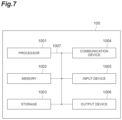
- FIG. 7 is a diagram illustrating an example of a hardware configuration of the RAN 100 according to the present embodiment.
- the RAN 100 described above may be physically configured as a computer device including a processor 1001 , a memory 1002 , a storage 1003 , a communication device 1004 , an input device 1005 , an output device 1006 , a bus 1007 , and the like.
- the hardware configuration of the RAN 100 may be configured to include one or a plurality of the respective devices illustrated in the figure, or may be configured without including some of the devices.
- Each function of the RAN 100 is realized by causing predetermined software (program) to be loaded into hardware such as the processor 1001 and the memory 1002 so that the processor 1001 performs computation and controls communication performed by the communication device 1004 and reading and/or writing of data from and to the memory 1002 and the storage 1003 .
- predetermined software program
- the processor 1001 operates, for example, an operating system to control the entire computer.
- the processor 1001 may be configured of a central processing unit (CPU) including an interface with a peripheral device, a control device, a computing device, a register, and the like.
- the priority processing unit 103 or the like may be realized by the processor 1001 .
- the processor 1001 causes a program (program code), a software module, and data to be loaded from the storage 1003 and/or the communication device 1004 into the memory 1002 , and executes various processes according to them.
- a program causing the computer to execute at least some of the operations described in the embodiment described above is used.
- the RAN 100 may be realized by a control program that is stored in the memory 1002 and operates in the processor 1001 .
- Other functional blocks may be similarly realized. Even though it has been described that various processes described above are executed by one processor 1001 ; however, the various processes may be executed simultaneously or sequentially by two or more processors 1001 .
- the processor 1001 may be implemented as one or more chips. Note that the program may be transmitted from a network through a telecommunications line.
- the memory 1002 is a computer-readable recording medium and may be configured of at least one of a ROM (Read Only Memory), an EPROM (Erasable Programmable ROM), an EEPROM (Electrically Erasable Programmable ROM), a RAM (Random Access Memory), and the like, for example.
- the memory 1002 may be referred to as a register, a cache, a main memory (main storage device), or the like.
- the memory 1002 can store a program (program code), a software module, and the like which can be executed for performing the radio communication method according to an embodiment of the present invention.
- the storage 1003 is a computer-readable recording medium and may be configured of at least one of an optical disk such as a CD-ROM (Compact Disc ROM), a hard disk drive, a flexible disk, a magneto-optical disk (for example, a compact disk, a digital versatile disk, a Blu-ray (registered trademark) disk), a smart card, a flash memory (for example, a card, a stick, a key drive), a floppy (registered trademark) disk, a magnetic strip, and the like, for example.
- the storage 1003 may be referred to as an auxiliary storage device.
- the storage medium described above may be an appropriate medium such as a database, a server, or the like including the memory 1002 and/or the storage 1003 .
- the storage unit 102 described above may be realized by the storage 1003 .
- the communication device 1004 is hardware (transmission and reception device) for performing communication between computers through a wired network and/or a wireless network, and is also referred to as a network device, a network controller, a network card, a communication module, or the like, for example.
- a network device a network controller, a network card, a communication module, or the like, for example.
- the receiving unit 101 , the forwarding processing unit 104 , and the like described above may be realized by the communication device 1004 .
- the input device 1005 is an input device (for example, a keyboard, a mouse, a microphone, a switch, a button, a sensor, or the like) that receives an input from the outside.
- the output device 1006 is an output device (for example, a display, a speaker, a LED lamp, or the like) that performs output to the outside. Note that a configuration may be possible in which the input device 1005 and the output device 1006 are integrated (for example, a touch panel).
- bus 1007 for communicating information.
- the bus 1007 may be configured of a single bus or may be configured by using different buses between respective devices.
- the RAN 100 may be configured to include hardware such as a microprocessor, a digital signal processor (DSP), an ASIC (Application Specific Integrated Circuit), a PLD (Programmable Logic Device), a FPGA (Field Programmable Gate Array), or the like, and some or all of the functional blocks may be realized by the hardware.
- the processor 1001 may be implemented by using at least one of the above examples of the hardware.
- Information notification is not limited to the aspect/embodiment described in the present Description, and may be performed by another method.
- information notification may be performed by physical layer signaling (for example, DCI (Downlink Control Information), UCI (Uplink Control Information)), upper layer signaling (for example, RRC (Radio Resource Control) signaling, MAC (Medium Access Control) signaling), notification information (MIB (Master Information Block), SIB (System Information Block))), other signals, or a combination thereof.
- the RRC signaling may be referred to as a RRC message, and may be, for example, a RRC Connection Setup message, a RRC Connection Reconfiguration message, or the like.
- LTE Long Term Evolution
- LTE-A Long Term Evolution-Advanced
- SUPER 3G IMT-Advanced
- 4G 5G
- FRA Full Radio Access
- W-CDMA registered trademark
- GSM registered trademark
- CDMA 2000 UMB (Ultra Mobile Broadband)
- IEEE 802.11 Wi-Fi
- IEEE 802.16 WiMAX
- IEEE 802.20 UWB (Ultra-WideBand)
- Bluetooth registered trademark
- Information or the like can be output from an upper layer (or a lower layer) to the lower layer (or the upper layer). Information or the like may be input and output via a plurality of network nodes.
- Information or the like that has been input or output may be stored in a specific place (for example, the memory), or may be managed by using a management table. Information or the like to be input or output can be overwritten, updated, or added. Information or the like that has been output may be deleted. Information or the like that has been input may be transmitted to another device.
- Judging may be performed by using a value ( 0 or 1 ) represented by 1 bit, may be performed by using a Boolean value (true or false), or may be performed by using numerical comparison (for example, comparison with a predetermined value).
- notification of predetermined information is not limited to being made explicitly, and may be made implicitly (for example, notification of the predetermined information is not made).
- Software should be interpreted widely so as to mean an instruction, an instruction set, a code, a code segment, a program code, a program, a sub-program, a software module, an application, a software application, a software package, a routine, a sub-routine, an object, an executable file, a thread of execution, a procedure, a function, and the like regardless of whether software may be referred to as software, firmware, middleware, microcode, hardware description language or referred to as another name.
- software, an instruction, and the like may be transmitted and received via a transmission medium.
- a transmission medium for example, in a case where software is transmitted from a website, a server, or another remote source by using a wired technology such as a coaxial cable, a fiber optic cable, a twisted-pair wire, and a digital subscriber line (DSL), and/or wireless technology such as infrared rays, radio, microwaves, or the like, the wired technology and/or the wireless technology are included within the definition of the transmission medium.
- a wired technology such as a coaxial cable, a fiber optic cable, a twisted-pair wire, and a digital subscriber line (DSL)
- wireless technology such as infrared rays, radio, microwaves, or the like
- Information, signals, and the like described in the present Description may be represented by using any of a variety of different techniques.
- data, an instruction, a command, information, a signal, a bit, a symbol, a chip, and the like that can be mentioned throughout the above description may be represented by a voltage, a current, an electromagnetic wave, a magnetic field or a magnetic particle, or a photo field or a photon, or any combination thereof.
- system and “network” used in the present Description are used interchangeably.
- information, parameters, and the like described in the present Description may be expressed by an absolute value, may be expressed by a relative value from a predetermined value, or may be expressed by other corresponding information.
- radio resources may be indicated by an index.
- the user terminal may be referred to by those skilled in the art as a subscriber station, a mobile unit, a subscriber unit, a wireless unit, a remote unit, a mobile device, a wireless device, a wireless communication device, a remote device, a mobile subscriber station, an access terminal, a mobile terminal, a wireless terminal, a remote terminal, a handset, a user agent, a mobile client, a client, or some other appropriate terms.
- determining and “determining” used in the present Description may encompass a wide variety of motions.
- “determining” or “determining” can include considering judging, calculating, computing, processing, deriving, investigating, looking up (for example, looking up in a table, a database, or another data structure), ascertaining, or the like, to be determined or determined.
- “determining” or “determining” can include considering receiving (for example, receiving information), transmitting (for example, transmitting information), input, output, or accessing (for example, accessing data in the memory), to be determined or determined.
- “determining” or “determining” can include considering resolving, selecting, choosing, establishing, comparing, or the like, to be determined or determined. That is, “determining” or “determining” can include considering a certain operation to be “determined” or “determined”.
- connection and “coupled” or every transformation of these terms mean every direct or indirect connection or coupling between two or more elements, and may include a case where there are one or more intermediate elements between two elements that are “connected” or “coupled” to each other. Coupling or connection between elements may be a physical coupling or connection, logical coupling or connection, or a combination thereof. In a case of being used in the present Description, it can be considered that two elements are “connected” or “coupled” to each other by using one or more electric wires, cables, and/or printed electric connections, and as several non-definitive and non-comprehensive examples, by using electromagnetic energy such as electromagnetic energy having a wavelength of a radio frequency region, a microwave region, and an optical (both visible and invisible) region.
- electromagnetic energy such as electromagnetic energy having a wavelength of a radio frequency region, a microwave region, and an optical (both visible and invisible) region.
Abstract
Description
- Non Patent Literature 1: 3GPP TS 23.501
- 101 Receiving unit
- 102 Storage unit
- 103 Priority processing unit
- 104 Forwarding processing unit
Claims (5)
Applications Claiming Priority (1)
| Application Number | Priority Date | Filing Date | Title |
|---|---|---|---|
| PCT/JP2018/029822 WO2020031303A1 (en) | 2018-08-08 | 2018-08-08 | Communication connection device and communication connection method |
Publications (2)
| Publication Number | Publication Date |
|---|---|
| US20210377781A1 US20210377781A1 (en) | 2021-12-02 |
| US11589258B2 true US11589258B2 (en) | 2023-02-21 |
Family
ID=69413272
Family Applications (1)
| Application Number | Title | Priority Date | Filing Date |
|---|---|---|---|
| US17/263,720 Active US11589258B2 (en) | 2018-08-08 | 2018-08-08 | Communication connection device and communication connection method |
Country Status (2)
| Country | Link |
|---|---|
| US (1) | US11589258B2 (en) |
| WO (1) | WO2020031303A1 (en) |
Families Citing this family (1)
| Publication number | Priority date | Publication date | Assignee | Title |
|---|---|---|---|---|
| US11528635B2 (en) * | 2021-01-12 | 2022-12-13 | Verizon Patent And Licensing Inc. | Method and system for radio resource management and network slicing |
Citations (8)
| Publication number | Priority date | Publication date | Assignee | Title |
|---|---|---|---|---|
| US20170164349A1 (en) * | 2015-12-08 | 2017-06-08 | Peiying Zhu | Method and system for performing network slicing in a radio access network |
| JP2018056867A (en) | 2016-09-30 | 2018-04-05 | 株式会社Nttドコモ | Communication system and communication method |
| US20180109973A1 (en) * | 2015-06-17 | 2018-04-19 | Huawei Technologies Co., Ltd. | Method and apparatus for handling data flow in wireless communication networks |
| US20190182752A1 (en) * | 2016-08-15 | 2019-06-13 | Huawei Technologies Co., Ltd. | Method and apparatus for network slice configuration |
| US20190238413A1 (en) * | 2016-09-29 | 2019-08-01 | Telefonaktiebolaget Lm Ericsson (Publ) | Quality Of Service Differentiation Between Network Slices |
| US20190364495A1 (en) * | 2017-02-03 | 2019-11-28 | Telefonaktiebolaget Lm Ericsson (Publ) | Access to a Communication System Employing Network Slicing Based on Pre-Configured Access Category |
| US20200120580A1 (en) * | 2017-06-16 | 2020-04-16 | Huawei Technologies Co., Ltd. | Communication method, network device, terminal device, and system |
| US20210084523A1 (en) * | 2017-12-15 | 2021-03-18 | Mokia Technologies Oy | Method for controlling data transmission by using network slices |
Family Cites Families (2)
| Publication number | Priority date | Publication date | Assignee | Title |
|---|---|---|---|---|
| EP3500048B1 (en) * | 2016-08-10 | 2021-11-03 | Nec Corporation | Radio access network node, wireless terminal, core network node, and methods for these |
| JP6660277B2 (en) * | 2016-09-30 | 2020-03-11 | 株式会社Nttドコモ | Slice management device, slice management method, and slice management system |
-
2018
- 2018-08-08 US US17/263,720 patent/US11589258B2/en active Active
- 2018-08-08 WO PCT/JP2018/029822 patent/WO2020031303A1/en active Application Filing
Patent Citations (8)
| Publication number | Priority date | Publication date | Assignee | Title |
|---|---|---|---|---|
| US20180109973A1 (en) * | 2015-06-17 | 2018-04-19 | Huawei Technologies Co., Ltd. | Method and apparatus for handling data flow in wireless communication networks |
| US20170164349A1 (en) * | 2015-12-08 | 2017-06-08 | Peiying Zhu | Method and system for performing network slicing in a radio access network |
| US20190182752A1 (en) * | 2016-08-15 | 2019-06-13 | Huawei Technologies Co., Ltd. | Method and apparatus for network slice configuration |
| US20190238413A1 (en) * | 2016-09-29 | 2019-08-01 | Telefonaktiebolaget Lm Ericsson (Publ) | Quality Of Service Differentiation Between Network Slices |
| JP2018056867A (en) | 2016-09-30 | 2018-04-05 | 株式会社Nttドコモ | Communication system and communication method |
| US20190364495A1 (en) * | 2017-02-03 | 2019-11-28 | Telefonaktiebolaget Lm Ericsson (Publ) | Access to a Communication System Employing Network Slicing Based on Pre-Configured Access Category |
| US20200120580A1 (en) * | 2017-06-16 | 2020-04-16 | Huawei Technologies Co., Ltd. | Communication method, network device, terminal device, and system |
| US20210084523A1 (en) * | 2017-12-15 | 2021-03-18 | Mokia Technologies Oy | Method for controlling data transmission by using network slices |
Non-Patent Citations (4)
| Title |
|---|
| 3GPP TS 23.501 V15.2.0, Release 15; "3rd Generation Partnership Project; Technical Specification Group Services and System Aspects; System Architecture for the 5G System; Stage 2;" Jun. 2018; Sophia Antipolis Valbonne, France (216 pages). |
| International Preliminary Report on Patentability for corresponding International Application No. PCT/JP2018/029822, dated Feb. 18, 2021 (6 pages). |
| International Search Report issued in Application No. PCT/JP2018/029822, dated Oct. 30, 2018 (3 pages). |
| Written Opinion issued in International Application No. PCT/JP2018/029822, dated Oct. 30, 2018 (3 pages). |
Also Published As
| Publication number | Publication date |
|---|---|
| WO2020031303A1 (en) | 2020-02-13 |
| US20210377781A1 (en) | 2021-12-02 |
Similar Documents
| Publication | Publication Date | Title |
|---|---|---|
| US10966270B2 (en) | User equipment and base station | |
| US11102827B2 (en) | Information notification method and mobile communication system | |
| US10993068B2 (en) | Communication control device and communication control method | |
| US20200137678A1 (en) | Slice management device and slice management method | |
| JP2018056868A (en) | Device, method and system for slice management | |
| EP4114057A1 (en) | Terminal, wireless base station, and wireless communication method | |
| US11589258B2 (en) | Communication connection device and communication connection method | |
| US11818753B2 (en) | Random access wait time setting method | |
| US20240007911A1 (en) | Radio base station, radio communication system, and radio communication method | |
| US20190394001A1 (en) | Base station and user apparatus | |
| US20190166642A1 (en) | Radio communication system | |
| US20230319823A1 (en) | Terminal, base station apparatus and feedback method | |
| EP4047988A1 (en) | Terminal | |
| US11646942B2 (en) | Slice operation device, communication system, and slice operation method | |
| JP7053846B2 (en) | Communication control device, selection device, communication control method and selection method | |
| US20220322420A1 (en) | Terminal and base station | |
| EP3962214A1 (en) | User device | |
| WO2019193764A1 (en) | Base station device and communication system | |
| US20240031884A1 (en) | Terminal and radio communication system | |
| JP2019036874A (en) | base station | |
| US20240129818A1 (en) | Radio base station and terminal | |
| US20240064719A1 (en) | Base station and communication method | |
| US20230308365A1 (en) | Management apparatus | |
| US20200022124A1 (en) | Base station and user equipment | |
| US20220330135A1 (en) | Network device |
Legal Events
| Date | Code | Title | Description |
|---|---|---|---|
| FEPP | Fee payment procedure |
Free format text: ENTITY STATUS SET TO UNDISCOUNTED (ORIGINAL EVENT CODE: BIG.); ENTITY STATUS OF PATENT OWNER: LARGE ENTITY |
|
| AS | Assignment |
Owner name: NTT DOCOMO, INC., JAPAN Free format text: ASSIGNMENT OF ASSIGNORS INTEREST;ASSIGNORS:KATSUMATA, YUKI;IWASHINA, SHIGERU;REEL/FRAME:055212/0123 Effective date: 20210107 |
|
| STPP | Information on status: patent application and granting procedure in general |
Free format text: DOCKETED NEW CASE - READY FOR EXAMINATION |
|
| STPP | Information on status: patent application and granting procedure in general |
Free format text: NON FINAL ACTION MAILED |
|
| STPP | Information on status: patent application and granting procedure in general |
Free format text: RESPONSE TO NON-FINAL OFFICE ACTION ENTERED AND FORWARDED TO EXAMINER |
|
| STPP | Information on status: patent application and granting procedure in general |
Free format text: FINAL REJECTION MAILED |
|
| STPP | Information on status: patent application and granting procedure in general |
Free format text: RESPONSE AFTER FINAL ACTION FORWARDED TO EXAMINER |
|
| STPP | Information on status: patent application and granting procedure in general |
Free format text: ADVISORY ACTION MAILED |
|
| STPP | Information on status: patent application and granting procedure in general |
Free format text: DOCKETED NEW CASE - READY FOR EXAMINATION |
|
| STPP | Information on status: patent application and granting procedure in general |
Free format text: NOTICE OF ALLOWANCE MAILED -- APPLICATION RECEIVED IN OFFICE OF PUBLICATIONS |
|
| STCF | Information on status: patent grant |
Free format text: PATENTED CASE |