US11588331B2 - Method and system for transferring a load in a thunder and lightning weather - Google Patents
Method and system for transferring a load in a thunder and lightning weather Download PDFInfo
- Publication number
- US11588331B2 US11588331B2 US16/987,864 US202016987864A US11588331B2 US 11588331 B2 US11588331 B2 US 11588331B2 US 202016987864 A US202016987864 A US 202016987864A US 11588331 B2 US11588331 B2 US 11588331B2
- Authority
- US
- United States
- Prior art keywords
- lightning
- loads
- transmission line
- control
- customer
- Prior art date
- Legal status (The legal status is an assumption and is not a legal conclusion. Google has not performed a legal analysis and makes no representation as to the accuracy of the status listed.)
- Active, expires
Links
Images


Classifications
-
- H—ELECTRICITY
- H02—GENERATION; CONVERSION OR DISTRIBUTION OF ELECTRIC POWER
- H02J—ELECTRIC POWER NETWORKS; CIRCUIT ARRANGEMENTS OR SYSTEMS FOR SUPPLYING OR DISTRIBUTING ELECTRIC POWER; SYSTEMS FOR STORING ELECTRIC ENERGY
- H02J3/00—Circuit arrangements for AC mains or AC distribution networks
- H02J3/04—Arrangements for connecting networks of the same frequency but supplied from different sources
- H02J3/06—Controlling the transfer of power between connected networks; Controlling load sharing between connected networks
-
- G—PHYSICS
- G06—COMPUTING OR CALCULATING; COUNTING
- G06Q—INFORMATION AND COMMUNICATION TECHNOLOGY [ICT] SPECIALLY ADAPTED FOR ADMINISTRATIVE, COMMERCIAL, FINANCIAL, MANAGERIAL OR SUPERVISORY PURPOSES; SYSTEMS OR METHODS SPECIALLY ADAPTED FOR ADMINISTRATIVE, COMMERCIAL, FINANCIAL, MANAGERIAL OR SUPERVISORY PURPOSES, NOT OTHERWISE PROVIDED FOR
- G06Q10/00—Administration; Management
- G06Q10/04—Forecasting or optimisation specially adapted for administrative or management purposes, e.g. linear programming or "cutting stock problem"
-
- G—PHYSICS
- G01—MEASURING; TESTING
- G01R—MEASURING ELECTRIC VARIABLES; MEASURING MAGNETIC VARIABLES
- G01R29/00—Arrangements for measuring or indicating electric quantities not covered by groups G01R19/00 - G01R27/00
- G01R29/08—Measuring electromagnetic field characteristics
- G01R29/0807—Measuring electromagnetic field characteristics characterised by the application
- G01R29/0814—Field measurements related to measuring influence on or from apparatus, components or humans, e.g. in ESD, EMI, EMC, EMP testing, measuring radiation leakage; detecting presence of micro- or radiowave emitters; dosimetry; testing shielding; measurements related to lightning
- G01R29/0842—Measurements related to lightning, e.g. measuring electric disturbances, warning systems
-
- G—PHYSICS
- G01—MEASURING; TESTING
- G01W—METEOROLOGY
- G01W1/00—Meteorology
- G01W1/10—Devices for predicting weather conditions
-
- G—PHYSICS
- G01—MEASURING; TESTING
- G01W—METEOROLOGY
- G01W1/00—Meteorology
- G01W1/16—Measuring atmospheric potential differences, e.g. due to electrical charges in clouds
-
- H—ELECTRICITY
- H02—GENERATION; CONVERSION OR DISTRIBUTION OF ELECTRIC POWER
- H02H—EMERGENCY PROTECTIVE CIRCUIT ARRANGEMENTS
- H02H3/00—Emergency protective circuit arrangements for automatic disconnection directly responsive to an undesired change from normal electric working condition with or without subsequent reconnection ; integrated protection
- H02H3/20—Emergency protective circuit arrangements for automatic disconnection directly responsive to an undesired change from normal electric working condition with or without subsequent reconnection ; integrated protection responsive to excess voltage
- H02H3/22—Emergency protective circuit arrangements for automatic disconnection directly responsive to an undesired change from normal electric working condition with or without subsequent reconnection ; integrated protection responsive to excess voltage of short duration, e.g. lightning
-
- H—ELECTRICITY
- H02—GENERATION; CONVERSION OR DISTRIBUTION OF ELECTRIC POWER
- H02J—ELECTRIC POWER NETWORKS; CIRCUIT ARRANGEMENTS OR SYSTEMS FOR SUPPLYING OR DISTRIBUTING ELECTRIC POWER; SYSTEMS FOR STORING ELECTRIC ENERGY
- H02J3/00—Circuit arrangements for AC mains or AC distribution networks
- H02J3/007—Arrangements for selectively connecting one or more loads to one or more power sources or power lines
- H02J3/0073—Arrangements for selectively connecting one or more loads to one or more power sources or power lines by providing alternative feeding paths when the main path fails
-
- Y—GENERAL TAGGING OF NEW TECHNOLOGICAL DEVELOPMENTS; GENERAL TAGGING OF CROSS-SECTIONAL TECHNOLOGIES SPANNING OVER SEVERAL SECTIONS OF THE IPC; TECHNICAL SUBJECTS COVERED BY FORMER USPC CROSS-REFERENCE ART COLLECTIONS [XRACs] AND DIGESTS
- Y04—INFORMATION OR COMMUNICATION TECHNOLOGIES HAVING AN IMPACT ON OTHER TECHNOLOGY AREAS
- Y04S—SYSTEMS INTEGRATING TECHNOLOGIES RELATED TO POWER NETWORK OPERATION, COMMUNICATION OR INFORMATION TECHNOLOGIES FOR IMPROVING THE ELECTRICAL POWER GENERATION, TRANSMISSION, DISTRIBUTION, MANAGEMENT OR USAGE, i.e. SMART GRIDS
- Y04S10/00—Systems supporting electrical power generation, transmission or distribution
- Y04S10/50—Systems or methods supporting the power network operation or management, involving a certain degree of interaction with the load-side end user applications
- Y04S10/52—Outage or fault management, e.g. fault detection or location
Definitions
- This application relates to the field of lightning protection and load control, for example, to a load transfer method and system in thunder and lightning weather.
- Lightning has always been an important natural factor endangering the operation safety of a power grid.
- the impact of lightning on the power grid is becoming more significant.
- one lightning storm may cause hundreds of power supply lines of the power grid to trip out, resulting in a large number of customers losing power and bringing huge economic losses. Therefore, lightning protection of the power grid is particularly important.
- a main lightning protection strategy adopted by the power system is to divert lightning energy through the multiple types of lightning protection devices installed on equipment and transmission lines, so as to reduce the probability that the equipment in the power grid trips out due to a lightning strike, thereby achieving static lightning protection.
- lightning rods are installed in and around substations to reduce the possibility that the lightning strikes equipment in the substations; lightning conductors are disposed above transmission lines to protect the lines below them; grounding devices of transmission towers are optimized to reduce the grounding resistance of the towers and weaken the ground potential rise caused by a lightning strike on the towers; line insulation is strengthened so that it can bear the overvoltage caused by a lightning strike.
- static lightning protection equipment can provide better protection for the equipment in the substations, but the lightning protection effect for transmission lines is not good. Due to the randomness of discharge channels of the lightning, the situation where the lightning bypasses the lightning conductors and strikes the phase line under the lightning conductors occurs occasionally. More common than the bypass strike is the arcing between the transmission tower and lines caused by the transmission tower being struck by the lightning. Due to the diversity and complexity of the geology and climatic conditions in transmission corridors, the effect of reducing the grounding resistance and strengthening the line insulation is not significant.
- the power grid adopts a rigid processing approach to the processing of the lightning protection and the loads, that is, if the normal operation of equipment and loads cannot be ensured, all of them will be cut off.
- the passive lightning protection measures for the power system mainly have the following limitations: the cost of the equipment is relatively high, and it will increase with the growth of the scale of power grid equipment; for transmission lines, the success rate of lightning protection is low; early warning is so lacking that almost no time is reserved for handling faults; after the trip-out, the load is cut off directly, causing large-area power outage and economic losses; a large amount of loads are disconnected from the grid in a short time, causing a great impact on the system.
- This application provides a load transfer method and system in thunder and lightning weather that can reasonably and effectively control a power grid, thereby reducing the impact of lightning on the power grid, increasing success rate of lightning protection and utilization rate of the power grid.
- This application provides a load transfer method in thunder and lightning weather.
- the method includes the following steps: lightning is detected and a position and time of a lightning strike are predicted to obtain a lightning prediction result; a transmission line possibly struck by lightning in a power grid is determined according to the lightning prediction result; a load transfer scheme is determined; and before the lightning occurs, at least part of loads on the transmission line possibly struck by the lightning is transferred according to the load transfer scheme.
- This application further provides a load transfer system in thunder and lightning weather for implementing the preceding method.
- the system includes a lightning detection module, a lightning prediction module, a control and decision system and an executive system.
- the lightning detection module is configured to detect lightning.
- the lightning prediction module is connected to the lightning detection module and configured to predict a position and time of a lightning strike to obtain a lightning prediction result.
- the control and decision system is connected to the lightning prediction module and configured to determine a transmission line possibly struck by lightning in a power grid according to the lightning prediction result and determine a load transfer scheme.
- the executive system is connected to the control and decision system and configured to, before the lightning occurs, execute the load transfer scheme to transfer at least part of loads on the transmission line possibly struck by the lightning.
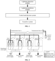
- FIG. 1 is a schematic diagram of a load transfer system in thunder and lightning weather according to an embodiment of this application.
- FIG. 2 is a schematic diagram of a normally operating power grid according to embodiment one of this application.
- FIG. 3 is a schematic diagram of load transferring before lightning occurs in a load transfer method in thunder and lightning weather according to embodiment one of this application.
- FIG. 4 is a schematic diagram of load transferring after lightning occurs according to embodiment one of this application.
- FIG. 5 is a schematic diagram of a load transfer system in thunder and lightning weather according to embodiment one of this application.
- FIG. 6 is a schematic diagram of a unified power flow controller (UPFC) facility according to embodiment two of this application.
- UPFC unified power flow controller
- FIG. 7 is a schematic diagram illustrating four modes of a UPFC facility during operating according to embodiment two of this application.
- FIG. 8 is a schematic diagram of a power flow adjustment when a line is threatened by a lightning strike according to embodiment two of this application.
- FIG. 9 is a schematic diagram of a load transfer system in thunder and lightning weather according to embodiment two of this application.
- An embodiment of this application provides a load transfer method in thunder and lightning weather.
- the method includes the following steps: lightning is detected and a position and time of a lightning strike are predicted to obtain a lightning prediction result; a transmission line possibly struck by lightning in a power grid is determined according to the lightning prediction result; a load transfer scheme is determined; and before the lightning occurs, at least part of loads on the transmission line possibly struck by the lightning is transferred according to the load transfer scheme.
- An embodiment of this application provides a load transfer system in thunder and lightning weather.
- the system includes a lightning detection module, a lightning prediction module, a control and decision system and an executive system.
- the lightning detection module is configured to detect lightning.
- the lightning prediction module is connected to the lightning detection module and configured to predict a position and time of a lightning strike to obtain a lightning prediction result.
- the control and decision system is connected to the lightning prediction module and configured to determine a transmission line possibly struck by lightning in a power grid according to the lightning prediction result and determine a load transfer scheme.
- the executive system is connected to the control and decision system and configured to, before the lightning occurs, execute the load transfer scheme to transfer at least part of loads on the transmission line possibly struck by the lightning.
- This embodiment provides a load transfer method in thunder and lightning weather.
- the method includes a preparation stage and an implementation stage as below.
- loads in a power grid are pre-classified according to significance of them, so as to obtain a classification result.
- the loads are classified into primary loads, important loads and general loads in descending order of the significance.
- the primary loads mainly include two types, one is a load that has a significant impact on production and operation activities and will cause significant economic losses in the case of power outage, such as blast furnaces in steel mills and spinning machines in textile mills, and the other is a load that has a significant impact on social operations, such as operating rooms in hospitals, urban subway lines and high-speed rail lines.
- the important loads mainly refer to a load that undertakes relatively large production tasks and can create relatively great economic values, but not causes additional losses in the case of power outage, such as machine tools that can be interrupted.
- the general loads refer to a load that is dominated by life power supplies and has a small impact after interruption, such as air conditioners, electric water heaters and lighting sources.
- the preceding scheme is an overall load classification scheme. In actual operation, it is necessary to classify the loads according to customers' will and different operating conditions in the power grid. For example, the significance of lighting sources applied in different times and places are apparently different. For some important loads, relevant agreements may be signed with customers, and in special cases such as lightning, such important loads are regarded as general load to be processed and certain compensations are provided.
- the customers are classified according to load sorts owned by the customers in the power grid. Almost all customers in the power grid have general loads so the customers in the power grid are classified into four sorts according to the combinations of primary loads and important loads owned by the customers, that is, according to the load sorts owned by the customers in the power grid.
- the four sorts of the customers are a sort-I customer, a sort-II customer, a sort-III customer and a sort-IV customer.
- the sort-I customer is a grid customer who owns at least both primary loads and important loads.
- the sort-II customer is a grid customer who owns at least primary loads but does not own important loads.
- the sort-III customer is a grid customer who owns at least important loads but does not own primary loads.
- the sort-IV customer is a grid customer who owns only general loads.
- This stage includes the steps described below.
- step 1 lightning is detected and a position and time of a lightning strike are predicted to obtain a lightning prediction result.
- step 2 a transmission line in the power grid possibly struck by lightning is determined according to the lightning prediction result.
- step 3 a load transfer scheme is determined, and before the lightning occurs, at least part of loads on the transmission line possibly struck by the lightning is transferred to a standby transmission line and/or a distributed micro-grid and/or a power storage device.
- the operation mode of the power grid is adjusted according to the lightning strike prediction result, and the load transfer scheme is determined according to the load classification result.
- the load transfer scheme may include the following: primary loads owned by the sort-I customer and the sort-II customer are transferred to the standby transmission line, important loads and/or general loads owned by the sort-I customer and the sort-II customer are transferred to the distributed micro-grid and/or the power storage device, and loads owned by the sort-III customer and the sort-IV customer are kept unchanged.
- a part of primary loads owned by the sort-I customer and the sort-II customer is transferred to the distributed micro-grid and/or the power storage device if the remaining capacity of the standby transmission line is not enough to carry the primary loads owned by the sort-I customer and the sort-II customer.
- transmission line A and transmission line B are two transmission lines which are standby for each other, and each of the transmission line A and the transmission line B carries certain loads and there are various sorts of customers on each of the transmission line A and the transmission line B.
- distributed power supplies and power storage devices there are a number of distributed power supplies and power storage devices in the region. These distributed power supplies and power storage devices are connected to the customers through a distributed micro-grid and are in a standby state under normal conditions, as shown in FIG. 2 .
- the operation mode of the power grid is adjusted according to the amount of the loads in the line regional power grid, the load rate on the transmission line B and the output levels of the distributed power supplies and the power storage devices.
- all the primary loads owned by the sort-I customer and the sort-II customer carried by the transmission line A should be transferred to the transmission line B, then the important loads and general loads of these customers are transferred to be powered by the distributed micro-grid, so that the burden of the transmission line B is eased, and the loads of the sort-III customer and sort-IV customer carried by the transmission line A are kept unchanged, as shown in FIG. 3 .
- step 4 after a period of time, the transmission line A trips out after struck by the lightning. At this time, the loads of the sort-I customer and the sort-II customer carried by the transmission line A have all been transferred and are not affected by the trip-out, and the remaining part of loads, that is, the loads of the sort-III customer and the sort-IV customer, are quickly transferred to the distributed micro-grid and/or power storage devices by the automatic apparatus after the trip-out.
- the transfer amount depends on the carrying capability of the micro-grid, and the power supplying of important loads is guaranteed in priority, as shown in FIG. 4 .
- step 5 after the lightning occurs, the transferred loads are recovered to the normal state before the transferring if the transmission line, such as the transmission line A, possibly struck by the lightning operates normally. If the fault of the transmission line A cannot be recovered in a short time, the subsequent processing is performed on the transferred loads according to the carrying capability of the transmission line B and the distributed power supplies until the transmission line A is recovered to operate.
- the preceding load transfer method in thunder and lightning weather is implemented by a load transfer system in thunder and lightning weather.
- the load transfer system in thunder and lightning weather mainly includes a lightning detection module, a lightning prediction module, a control and decision system and an executive module.
- the system may further include a geographic information system, a main-grid monitoring system and a micro-grid monitoring system.
- the lightning detection module is configured to detect lightning.
- the lightning prediction module is connected to the lightning detection module and configured to predict a position and time of a lightning strike to obtain a lightning prediction result.
- the lightning detection module and the lightning prediction module use lightning sensors installed on the ground to measure the variation in electric field intensity in the air and the electromagnetic radiation generated by lightning activities and predict the position and the approximate time of the lightning strike by performing a time-domain quantitative analysis on the lightning activities on the basis of the broad-spectrum frequency-division sensing technology and in combination with the time-domain differential technology. This technology has been covered in a previously applied patent (application number CN201710615287.2) and thus is not detailed here.
- the control and decision system is connected to the lightning prediction module and configured to determine a transmission line possibly struck by lightning in a power grid according to a lightning prediction result, determine a load transfer scheme, and send out a corresponding control signal.
- the executive module is connected to the control and decision system and the power grid and the executive module is configured to execute the load transfer scheme according to the control signal, and before the lightning occurs, transfer at least part of loads on the transmission line possibly struck by the lightning to a standby transmission line and/or a distributed micro-grid and/or a power storage device.
- the geographic information system is connected to the control and decision system and configured to provide the control and decision system with geographic information required in determining the transmission line possibly struck by the lightning in the power grid.
- the main-grid monitoring system is connected to the control and decision system and configured to provide the control and decision system with operation status data of the power grid.
- the micro-grid monitoring system is connected to the control and decision system and configured to provide the control and decision system with operation status data of the distributed micro-grid.
- the lightning early warning system in this embodiment has an accuracy rate of over 99% in predicting lightning strikes within a core region covering 200 square kilometers.
- This embodiment provides a load transfer method in thunder and lightning weather.
- the method includes the steps described below.
- step 1 lightning is detected and a position and time of a lightning strike are predicted to obtain a lightning prediction result.
- lightning detection is implemented by a lightning detection module.
- the position and time of the lightning strike being predicted to obtain the lightning prediction result is implemented by the lightning prediction module.
- the lightning detection module and the lightning prediction module constitute a lightning early warning system that can send out early warning signals.
- the lightning detection module and the lightning prediction module use lightning sensors installed on the ground to measure the variation in electric field intensity in the air and the electromagnetic radiation generated by lightning activities and predict the position and the approximate time of the lightning strike by performing a time-domain quantitative analysis on the lightning activities on the basis of the broad-spectrum frequency-division sensing technology and in combination with the time-domain differential technology.
- This technology has been covered in the previously applied patent (application number CN201710615287.2) and thus is not detailed here.
- step 2 a transmission line possibly struck by lightning in a power grid are determined according to the lightning prediction result, and the transmission line possibly struck by the lightning and an adjacent line of the transmission line are taken as adjustment objects.
- the geographic information provided by the geographic information system according to the lightning prediction result is compared with the topology of the power grid, and the transmission line that may trip out due to the lightning strike and the adjacent line associated with the transmission line are found.
- This step is implemented by the control and decision system.
- step 3 the control quantity of each adjustment object is calculated and distributed and sent to a corresponding UPFC facility according to the load condition of each adjustment object and the power flow control capability of the corresponding UPFC facility. This step is also implemented by the control and decision system.
- step 4 before the lightning occurs, an early warning signal and a control quantity sent out by the lightning prediction module are sent to the UPFC facility corresponding to the determined adjustment object.
- Each UPFC facility perform the power flow adjustment of the corresponding adjustment object according to the received control quantity, to transfer at least part of loads on the transmission line possibly struck by the lightning to the adjacent line.
- the principle of the UPFC facility is shown in FIG. 6 , and the UPFC facility mainly includes two parts: a main circuit and a control unit.
- the control unit of the UPFC facility includes a controller connected to the control and decision system.
- the main circuit of the UPFC facility includes a parallel converter and a series converter that are controlled by the controller.
- the parallel converter and the series converter are in coupling connection through a common-side capacitor and are connected to the power grid through a parallel transformer and a series transformer respectively, so as to be connected to a controlled transmission line.
- the series converter may inject a voltage with variable amplitude and phase into the grid system through the series transformer and the voltage can be superimposed, through in series, on a line where the UPFC is located, so as to achieve phase shift adjustment and series compensation of the line voltage.
- the power flow on a transmission line depends on the voltage amplitude and phase angle of a node, so the active and reactive power transmitted on the line can be flexibly controlled through adjusting the voltage of the UPFC access point.
- the main function of the parallel converter is to absorb active power from the power grid through the parallel transformer and then transmit the active power to the series converter through a direct-current connection line.
- FIG. 7 shows four modes during UPFC operating, namely modes of voltage adjustment, series compensation, phase angle adjustment and power flow control.
- the output voltage of the series transformer has a phase same as or opposite to the line voltage, and the amplitude of the line voltage after the superimposition is the original amplitude plus or minus the output voltage of the series transformer, and the phase does not change;
- (b) of FIG. 7 shows the series compensation mode, and in this case, the phase of the compensation voltage and the phase of the line current differ by 90°;
- FIG. 7 shows the phase angle adjustment mode, and in this case, the UPFC is equivalent to a phase shifter, which only changes the phase angle of the line voltage but does not change the amplitude of the line voltage; (d) of FIG. 7 shows the power flow control mode, which is a combination of the preceding three modes.
- the UPFC should operate in the power flow control mode.
- the lightning early warning system simultaneously transmits an alarm signal to the controllers of the UPFCs on lines A, B and C, where the lines B and C are adjacent lines of the line A.
- the control and decision system transmits a calculated control quantity to the UPFC on the line A, a calculated control quantity to the UPFC on the line B, and a calculated control quantity to the UPFC on the line C respectively.
- the UPFC on the line A controls its operation state through adjusting the converter, so as to enable the series transformer to output a voltage whose phase lags behind a phase of an original line voltage on the transmission line A possibly struck by the lightning, so that the amplitude of the line voltage after the superimposition is reduced and the phase of the line voltage after the superimposition lags behind, thereby reducing the power flow on the line A.
- the UPFC on the line B and the UPFC on the line C each adjusts the series output voltage, and the UPFC on the line B outputs a voltage whose phase leads ahead a phase of an original line voltage on the adjacent line B and the UPFC on the line C outputs a voltage whose phase leads ahead a phase of an original line voltage on the adjacent line C, so that the amplitude of the voltage on the line after the superimposition increases and the phase leads ahead, thereby increasing the power flow passing through each of the two lines and thus achieving the transfer of loads on the line A to the lines B and C.
- step 5 after the lightning occurs and the threat of the lightning strike is removed, whether the transmission line A possibly struck by the lightning trips out is determined by using a telesignal of the switch. If the transmission line A possibly struck by the lightning does not trip out, a recovery signal is sent to the UPFC controller on each of the three lines, and the UPFC performs an opposite operation, so as to enable the loads recover to a state before the transferring. If the line A has tripped out, it is necessary to send a recovery signal to the UPFC on each line side after the completion of the accident handling, the completion of the line defect elimination work, and the reset of the telesignal of the switch.
- the preceding power-grid power flow adjustment method in thunder and lightning weather is implemented by a power-grid power flow adjustment system in thunder and lightning weather.
- the power-grid power flow adjustment system in thunder and lightning weather mainly includes a lightning detection module, a lightning prediction module, a control and decision system, and a number of UPFC facilities configured in the power grid.
- the power-grid power flow adjustment system further includes a geographic information system and a power grid information system.
- the lightning detection module is configured to detect lightning.
- the lightning prediction module is connected to the lightning detection module and configured to predict a position and time of a lightning strike to obtain a lightning prediction result.
- the two modules form a lightning detection system, which can be implemented based on the related art.
- a lightning sensor detects the electromagnetic radiation generated during the forming of the lightning and the variation in the electric field in the air during the forming of the lightning and transmits the waveform data to the lightning prediction module.
- the lightning prediction module predicts the lightning situation in the region within a period of time based on the current waveform and sends the prediction result to the control and decision system.
- the control and decision system is connected to a lightning prediction module and configured to determine a transmission line possibly struck by lightning and an adjacent line of the transmission line in the power grid and take the transmission line possibly struck by the lightning and the adjacent line as adjustment objects, calculate and allocate the control quantity of each adjustment object according to the load condition of each adjustment object and the power flow control capability of a corresponding UPFC facility and send the control quantity to the corresponding UPFC facility.
- the control and decision system selects a line that requires load adjustment according to the lightning strike prediction result and in combination with regional geographic information, the topology of the power grid and real-time load conditions of equipment, and then sends the adjustment amount to the controller of the UPFC corresponding to the line.
- Each UPFC facility is connected to the control and decision system separately and connected to a corresponding transmission line.
- Each UPFC facility is configured to perform the power flow adjustment of the corresponding adjustment object according to the received control quantity, to transfer at least part of loads on the transmission line possibly struck by the lightning to the adjacent line.
- the controller of the UPFC facility After the controller of the UPFC facility performs the power flow adjustment, the controller of the UPFC facility returns the adjustment result to the control and decision system, and the control and decision system updates power grid information according to the feedback.
- the geographic information system connected to the control and decision system is configured to provide the control and decision system with the geographic information required in determining the transmission line possibly struck by the lightning and the adjacent line.
- the power grid information system connected to the control and decision system is configured to provide the control and decision system with power grid information and update power grid information under the control of the control and decision system.
- This scheme proposes a power flow control strategy for a power grid in lightning storm weather, that is, “active protection and active control”, and designs a corresponding collaborative system that organically combines dynamic lightning protection with UPFC.
- the scheme has the advantages described below.
- High accuracy rate of lightning strike prediction the position and the approximate time of the lightning strike within a range of hundreds of kilometers can be accurately predicted through measuring electromagnetic radiation and electric field intensity in the atmosphere by the sensors, so that precautionary measures can be taken for the equipment in the lightning region.
- the accuracy rate of lightning strike prediction has reached more than 99% in the core detection region covering 200 square kilometers, and the prediction error of the position of the lightning strike is between 100-250 m. This is enough to satisfy the accuracy requirements in prediction of a fault caused by the trip-out of a lightning-struck line.
- the UPFC can reasonably allocate the power flow according to the architecture and real-time operation of the power grid to achieve the precise adjustment and control of the power flow of the power grid, thereby avoiding excessive power flow of a single circuit. Moreover, since the power flow of the line is transferred in advance, the power flow changes little at the moment of tripping out caused by the lightning strike, so the impact on the power grid is also small, thereby improving the stability of the power grid when a lightning strike accident occurs. This enables the lightning accident to be restricted within a small range without threatening the stability of the power grid.
Landscapes
- Engineering & Computer Science (AREA)
- Environmental & Geological Engineering (AREA)
- Physics & Mathematics (AREA)
- Business, Economics & Management (AREA)
- Economics (AREA)
- Strategic Management (AREA)
- Environmental Sciences (AREA)
- Biodiversity & Conservation Biology (AREA)
- Ecology (AREA)
- General Physics & Mathematics (AREA)
- Atmospheric Sciences (AREA)
- Human Resources & Organizations (AREA)
- Life Sciences & Earth Sciences (AREA)
- Quality & Reliability (AREA)
- Development Economics (AREA)
- Electromagnetism (AREA)
- Entrepreneurship & Innovation (AREA)
- Marketing (AREA)
- Operations Research (AREA)
- Game Theory and Decision Science (AREA)
- Tourism & Hospitality (AREA)
- General Business, Economics & Management (AREA)
- Theoretical Computer Science (AREA)
- Power Engineering (AREA)
- Supply And Distribution Of Alternating Current (AREA)
- Remote Monitoring And Control Of Power-Distribution Networks (AREA)
Abstract
Description
Claims (17)
Applications Claiming Priority (4)
| Application Number | Priority Date | Filing Date | Title |
|---|---|---|---|
| CN201910732890.8A CN110311377B (en) | 2019-08-09 | 2019-08-09 | Method and system for source network load storage control and load flexible switching in lightning climate |
| CN201910732908.4A CN110417024A (en) | 2019-08-09 | 2019-08-09 | Electric network swim adjusting method and system under thunder and lightning weather |
| CN201910732908.4 | 2019-08-09 | ||
| CN201910732890.8 | 2019-08-09 |
Publications (2)
| Publication Number | Publication Date |
|---|---|
| US20210066914A1 US20210066914A1 (en) | 2021-03-04 |
| US11588331B2 true US11588331B2 (en) | 2023-02-21 |
Family
ID=74679364
Family Applications (1)
| Application Number | Title | Priority Date | Filing Date |
|---|---|---|---|
| US16/987,864 Active 2041-06-30 US11588331B2 (en) | 2019-08-09 | 2020-08-07 | Method and system for transferring a load in a thunder and lightning weather |
Country Status (1)
| Country | Link |
|---|---|
| US (1) | US11588331B2 (en) |
Families Citing this family (12)
| Publication number | Priority date | Publication date | Assignee | Title |
|---|---|---|---|---|
| CN113063993B (en) * | 2021-03-10 | 2025-01-21 | 国网安徽省电力有限公司电力科学研究院 | A lightning trip monitoring device and method thereof |
| JP7611769B2 (en) * | 2021-05-27 | 2025-01-10 | 株式会社日立製作所 | Power system planning and operation device, method and system |
| CN113809822A (en) * | 2021-08-12 | 2021-12-17 | 国网浙江嘉善县供电有限公司 | An auxiliary decision-making system for rapid load transfer in distribution network based on PI database |
| US11444476B1 (en) * | 2021-09-23 | 2022-09-13 | State Grid Jiangsu Electric Power Co., Ltd. | Lightning strike probability-based coordinated power control method for energy storage system and load |
| CN114355059B (en) * | 2022-01-11 | 2024-11-15 | 武汉三江中电科技有限责任公司 | A lightning monitoring system based on silicon photocells and multi-channel narrow-band filters |
| WO2023208019A1 (en) * | 2022-04-27 | 2023-11-02 | 国网江苏省电力有限公司苏州供电分公司 | Thunderstorm wind-solar storage integrated electric vehicle charging station response system and method |
| CN115276062B (en) * | 2022-07-22 | 2024-04-26 | 国网江苏省电力有限公司苏州供电分公司 | Wind-storage combined system power two-layer regulation and control method and system based on lightning probability |
| CN116011814A (en) * | 2022-12-30 | 2023-04-25 | 广西电网有限责任公司电力科学研究院 | A main transformer risk management and control system |
| CN116073523B (en) * | 2023-03-14 | 2023-06-16 | 广东电网有限责任公司梅州供电局 | Power supply system, low-voltage distribution line monitoring method and monitoring device thereof |
| CN118763673B (en) * | 2024-09-09 | 2024-12-31 | 南方电网人工智能科技有限公司 | Self-adaptive wiring method and device for power distribution network and computer equipment |
| CN120109816B (en) * | 2025-02-26 | 2026-01-20 | 南方电网科学研究院有限责任公司 | Power grid tide optimization method based on accident chain in extreme weather and related device |
| CN120262465B (en) * | 2025-05-21 | 2025-08-19 | 国网上海市电力公司 | Power balancing method and system for multiple parallel lines of new energy power grid |
Citations (2)
| Publication number | Priority date | Publication date | Assignee | Title |
|---|---|---|---|---|
| CN106410792A (en) | 2016-10-17 | 2017-02-15 | 国网江苏省电力公司苏州供电公司 | Power grid lightning protection method and system |
| CN107453352A (en) | 2017-07-13 | 2017-12-08 | 国网江苏省电力公司苏州供电公司 | A kind of thunder and lightning dynamic protection method and system |
-
2020
- 2020-08-07 US US16/987,864 patent/US11588331B2/en active Active
Patent Citations (4)
| Publication number | Priority date | Publication date | Assignee | Title |
|---|---|---|---|---|
| CN106410792A (en) | 2016-10-17 | 2017-02-15 | 国网江苏省电力公司苏州供电公司 | Power grid lightning protection method and system |
| CN106410792B (en) | 2016-10-17 | 2019-03-15 | 国网江苏省电力公司苏州供电公司 | Method and system for lightning protection of power grid |
| CN107453352A (en) | 2017-07-13 | 2017-12-08 | 国网江苏省电力公司苏州供电公司 | A kind of thunder and lightning dynamic protection method and system |
| US20200059093A1 (en) * | 2017-07-13 | 2020-02-20 | State Grid Jiangsu Electric Power Co., Ltd Suzhou Branch | Dynamic thunder and lightning protection method and system |
Also Published As
| Publication number | Publication date |
|---|---|
| US20210066914A1 (en) | 2021-03-04 |
Similar Documents
| Publication | Publication Date | Title |
|---|---|---|
| US11588331B2 (en) | Method and system for transferring a load in a thunder and lightning weather | |
| Monadi et al. | Centralized protection strategy for medium voltage DC microgrids | |
| CN104391211B (en) | A kind of repair based on condition of component on-line detecting system for series compensation device | |
| CN103124068B (en) | A kind of anti-island protect system of distributed power generation grid-connected system and guard method thereof | |
| US20150005970A1 (en) | Distributed Control in Electric Power Delivery Systems | |
| CN103336220A (en) | Method and apparatus for monitoring and positioning fault in power distribution network | |
| CN108173264A (en) | A kind of Optimal Configuration Method of fault current limiter | |
| CN108957245A (en) | A kind of flexible direct current power distribution network monopole fault identification method based on total failure electric current | |
| CN107167709A (en) | A kind of electric network fault localization method and alignment system | |
| CN105186467A (en) | Distributed power fault analysis method and protection system | |
| CN101299541B (en) | Supervoltage magnetic-controlled shunt reactor excitation equipment | |
| CN105391033B (en) | Layering for large-scale wind power generation divides domain anti-isolated island guard method | |
| CN105372529B (en) | Grid islanding detection and anti-islanding protection method for large-scale wind power | |
| CN105591371B (en) | Anti- isolated island Protection control system based on photovoltaic plant power control system and method | |
| CN105703341B (en) | There is the layering point domain isolated island guard method of anti-jump function for large-scale wind power | |
| Zbunjak et al. | Advanced control and system integrity protection schemes of Croatian power transmission network with integrated renewable energy sources | |
| Xiang et al. | A Method of Dynamic Control of the Power Grid based on Real-time Lightning Tracking | |
| CN110311377B (en) | Method and system for source network load storage control and load flexible switching in lightning climate | |
| CN107516908B (en) | Island protection method in distribution network area under distributed photovoltaic scale access | |
| CN104901321A (en) | Long-distance cable power transmission and distribution network voltage control system | |
| CN110417024A (en) | Electric network swim adjusting method and system under thunder and lightning weather | |
| CN105978017B (en) | There is the method for detecting and protecting isolated island of anti-jump function for large-scale wind power | |
| Mujie et al. | Research on the Influence of 500 kV Fault Current Limiter on Line Distance Protection | |
| CN105375520B (en) | There is the island detection method of anti-jump function for large-scale wind power | |
| Hao et al. | Research on Active Distribution Network Monitoring and Police Method of Substation Based on Fault Tree |
Legal Events
| Date | Code | Title | Description |
|---|---|---|---|
| AS | Assignment |
Owner name: STATE GRID SUZHOU POWER SUPPLY COMPANY, CHINA Free format text: ASSIGNMENT OF ASSIGNORS INTEREST;ASSIGNORS:CAI, YUNFENG;TONG, CHONG;WANG, NING;AND OTHERS;REEL/FRAME:053437/0908 Effective date: 20200727 |
|
| FEPP | Fee payment procedure |
Free format text: ENTITY STATUS SET TO UNDISCOUNTED (ORIGINAL EVENT CODE: BIG.); ENTITY STATUS OF PATENT OWNER: LARGE ENTITY |
|
| STPP | Information on status: patent application and granting procedure in general |
Free format text: APPLICATION DISPATCHED FROM PREEXAM, NOT YET DOCKETED |
|
| AS | Assignment |
Owner name: STATE GRID JIANGSU ELECTRIC POWER CO., LTD. MARKETING CENTER, CHINA Free format text: ASSIGNMENT OF ASSIGNORS INTEREST;ASSIGNOR:STATE GRID SUZHOU POWER SUPPLY COMPANY;REEL/FRAME:054699/0747 Effective date: 20201130 Owner name: STATE GRID JIANGSU ELECTRIC POWER CO., LTD., CHINA Free format text: ASSIGNMENT OF ASSIGNORS INTEREST;ASSIGNOR:STATE GRID SUZHOU POWER SUPPLY COMPANY;REEL/FRAME:054699/0747 Effective date: 20201130 Owner name: STATE GRID SUZHOU POWER SUPPLY COMPANY, CHINA Free format text: ASSIGNMENT OF ASSIGNORS INTEREST;ASSIGNOR:STATE GRID SUZHOU POWER SUPPLY COMPANY;REEL/FRAME:054699/0747 Effective date: 20201130 Owner name: STATE GRID SUZHOU POWER SUPPLY COMPANY, CHINA Free format text: ASSIGNMENT OF ASSIGNORS INTEREST;ASSIGNORS:CAI, YUNFENG;TONG, CHONG;WANG, NING;AND OTHERS;REEL/FRAME:054699/0909 Effective date: 20200930 Owner name: STATE GRID JIANGSU ELECTRIC POWER CO., LTD. MARKETING CENTER, CHINA Free format text: ASSIGNMENT OF ASSIGNORS INTEREST;ASSIGNORS:CAI, YUNFENG;TONG, CHONG;WANG, NING;AND OTHERS;REEL/FRAME:054699/0909 Effective date: 20200930 Owner name: STATE GRID JIANGSU ELECTRIC POWER CO., LTD., CHINA Free format text: ASSIGNMENT OF ASSIGNORS INTEREST;ASSIGNORS:CAI, YUNFENG;TONG, CHONG;WANG, NING;AND OTHERS;REEL/FRAME:054699/0909 Effective date: 20200930 |
|
| STPP | Information on status: patent application and granting procedure in general |
Free format text: DOCKETED NEW CASE - READY FOR EXAMINATION |
|
| STPP | Information on status: patent application and granting procedure in general |
Free format text: NON FINAL ACTION MAILED |
|
| STPP | Information on status: patent application and granting procedure in general |
Free format text: RESPONSE TO NON-FINAL OFFICE ACTION ENTERED AND FORWARDED TO EXAMINER |
|
| STPP | Information on status: patent application and granting procedure in general |
Free format text: NOTICE OF ALLOWANCE MAILED -- APPLICATION RECEIVED IN OFFICE OF PUBLICATIONS |
|
| STCF | Information on status: patent grant |
Free format text: PATENTED CASE |