US11577442B2 - Polymeric tube forming apparatus with a multi-dimensional control system - Google Patents
Polymeric tube forming apparatus with a multi-dimensional control system Download PDFInfo
- Publication number
- US11577442B2 US11577442B2 US17/065,633 US202017065633A US11577442B2 US 11577442 B2 US11577442 B2 US 11577442B2 US 202017065633 A US202017065633 A US 202017065633A US 11577442 B2 US11577442 B2 US 11577442B2
- Authority
- US
- United States
- Prior art keywords
- tube
- core tube
- exterior
- forming apparatus
- tip
- Prior art date
- Legal status (The legal status is an assumption and is not a legal conclusion. Google has not performed a legal analysis and makes no representation as to the accuracy of the status listed.)
- Active, expires
Links
Images


Classifications
-
- B—PERFORMING OPERATIONS; TRANSPORTING
- B29—WORKING OF PLASTICS; WORKING OF SUBSTANCES IN A PLASTIC STATE IN GENERAL
- B29C—SHAPING OR JOINING OF PLASTICS; SHAPING OF MATERIAL IN A PLASTIC STATE, NOT OTHERWISE PROVIDED FOR; AFTER-TREATMENT OF THE SHAPED PRODUCTS, e.g. REPAIRING
- B29C48/00—Extrusion moulding, i.e. expressing the moulding material through a die or nozzle which imparts the desired form; Apparatus therefor
- B29C48/25—Component parts, details or accessories; Auxiliary operations
- B29C48/30—Extrusion nozzles or dies
- B29C48/32—Extrusion nozzles or dies with annular openings, e.g. for forming tubular articles
- B29C48/325—Extrusion nozzles or dies with annular openings, e.g. for forming tubular articles being adjustable, i.e. having adjustable exit sections
-
- B—PERFORMING OPERATIONS; TRANSPORTING
- B29—WORKING OF PLASTICS; WORKING OF SUBSTANCES IN A PLASTIC STATE IN GENERAL
- B29C—SHAPING OR JOINING OF PLASTICS; SHAPING OF MATERIAL IN A PLASTIC STATE, NOT OTHERWISE PROVIDED FOR; AFTER-TREATMENT OF THE SHAPED PRODUCTS, e.g. REPAIRING
- B29C48/00—Extrusion moulding, i.e. expressing the moulding material through a die or nozzle which imparts the desired form; Apparatus therefor
- B29C48/03—Extrusion moulding, i.e. expressing the moulding material through a die or nozzle which imparts the desired form; Apparatus therefor characterised by the shape of the extruded material at extrusion
- B29C48/09—Articles with cross-sections having partially or fully enclosed cavities, e.g. pipes or channels
-
- B—PERFORMING OPERATIONS; TRANSPORTING
- B29—WORKING OF PLASTICS; WORKING OF SUBSTANCES IN A PLASTIC STATE IN GENERAL
- B29C—SHAPING OR JOINING OF PLASTICS; SHAPING OF MATERIAL IN A PLASTIC STATE, NOT OTHERWISE PROVIDED FOR; AFTER-TREATMENT OF THE SHAPED PRODUCTS, e.g. REPAIRING
- B29C48/00—Extrusion moulding, i.e. expressing the moulding material through a die or nozzle which imparts the desired form; Apparatus therefor
- B29C48/25—Component parts, details or accessories; Auxiliary operations
- B29C48/252—Drive or actuation means; Transmission means; Screw supporting means
- B29C48/2522—Shaft or screw supports, e.g. bearings
-
- B—PERFORMING OPERATIONS; TRANSPORTING
- B29—WORKING OF PLASTICS; WORKING OF SUBSTANCES IN A PLASTIC STATE IN GENERAL
- B29C—SHAPING OR JOINING OF PLASTICS; SHAPING OF MATERIAL IN A PLASTIC STATE, NOT OTHERWISE PROVIDED FOR; AFTER-TREATMENT OF THE SHAPED PRODUCTS, e.g. REPAIRING
- B29C48/00—Extrusion moulding, i.e. expressing the moulding material through a die or nozzle which imparts the desired form; Apparatus therefor
- B29C48/25—Component parts, details or accessories; Auxiliary operations
- B29C48/252—Drive or actuation means; Transmission means; Screw supporting means
- B29C48/2528—Drive or actuation means for non-plasticising purposes, e.g. dosing unit
-
- B—PERFORMING OPERATIONS; TRANSPORTING
- B29—WORKING OF PLASTICS; WORKING OF SUBSTANCES IN A PLASTIC STATE IN GENERAL
- B29C—SHAPING OR JOINING OF PLASTICS; SHAPING OF MATERIAL IN A PLASTIC STATE, NOT OTHERWISE PROVIDED FOR; AFTER-TREATMENT OF THE SHAPED PRODUCTS, e.g. REPAIRING
- B29C48/00—Extrusion moulding, i.e. expressing the moulding material through a die or nozzle which imparts the desired form; Apparatus therefor
- B29C48/25—Component parts, details or accessories; Auxiliary operations
- B29C48/255—Flow control means, e.g. valves
- B29C48/2556—Flow control means, e.g. valves provided in or in the proximity of dies
-
- B—PERFORMING OPERATIONS; TRANSPORTING
- B29—WORKING OF PLASTICS; WORKING OF SUBSTANCES IN A PLASTIC STATE IN GENERAL
- B29C—SHAPING OR JOINING OF PLASTICS; SHAPING OF MATERIAL IN A PLASTIC STATE, NOT OTHERWISE PROVIDED FOR; AFTER-TREATMENT OF THE SHAPED PRODUCTS, e.g. REPAIRING
- B29C48/00—Extrusion moulding, i.e. expressing the moulding material through a die or nozzle which imparts the desired form; Apparatus therefor
- B29C48/25—Component parts, details or accessories; Auxiliary operations
- B29C48/256—Exchangeable extruder parts
- B29C48/2566—Die parts
-
- B—PERFORMING OPERATIONS; TRANSPORTING
- B29—WORKING OF PLASTICS; WORKING OF SUBSTANCES IN A PLASTIC STATE IN GENERAL
- B29C—SHAPING OR JOINING OF PLASTICS; SHAPING OF MATERIAL IN A PLASTIC STATE, NOT OTHERWISE PROVIDED FOR; AFTER-TREATMENT OF THE SHAPED PRODUCTS, e.g. REPAIRING
- B29C48/00—Extrusion moulding, i.e. expressing the moulding material through a die or nozzle which imparts the desired form; Apparatus therefor
- B29C48/25—Component parts, details or accessories; Auxiliary operations
- B29C48/256—Exchangeable extruder parts
- B29C48/2568—Inserts
- B29C48/25686—Inserts for dies
-
- B—PERFORMING OPERATIONS; TRANSPORTING
- B29—WORKING OF PLASTICS; WORKING OF SUBSTANCES IN A PLASTIC STATE IN GENERAL
- B29C—SHAPING OR JOINING OF PLASTICS; SHAPING OF MATERIAL IN A PLASTIC STATE, NOT OTHERWISE PROVIDED FOR; AFTER-TREATMENT OF THE SHAPED PRODUCTS, e.g. REPAIRING
- B29C48/00—Extrusion moulding, i.e. expressing the moulding material through a die or nozzle which imparts the desired form; Apparatus therefor
- B29C48/25—Component parts, details or accessories; Auxiliary operations
- B29C48/266—Means for allowing relative movements between the apparatus parts, e.g. for twisting the extruded article or for moving the die along a surface to be coated
-
- B—PERFORMING OPERATIONS; TRANSPORTING
- B29—WORKING OF PLASTICS; WORKING OF SUBSTANCES IN A PLASTIC STATE IN GENERAL
- B29C—SHAPING OR JOINING OF PLASTICS; SHAPING OF MATERIAL IN A PLASTIC STATE, NOT OTHERWISE PROVIDED FOR; AFTER-TREATMENT OF THE SHAPED PRODUCTS, e.g. REPAIRING
- B29C48/00—Extrusion moulding, i.e. expressing the moulding material through a die or nozzle which imparts the desired form; Apparatus therefor
- B29C48/25—Component parts, details or accessories; Auxiliary operations
- B29C48/30—Extrusion nozzles or dies
- B29C48/32—Extrusion nozzles or dies with annular openings, e.g. for forming tubular articles
- B29C48/325—Extrusion nozzles or dies with annular openings, e.g. for forming tubular articles being adjustable, i.e. having adjustable exit sections
- B29C48/327—Extrusion nozzles or dies with annular openings, e.g. for forming tubular articles being adjustable, i.e. having adjustable exit sections with centering means
-
- B—PERFORMING OPERATIONS; TRANSPORTING
- B29—WORKING OF PLASTICS; WORKING OF SUBSTANCES IN A PLASTIC STATE IN GENERAL
- B29C—SHAPING OR JOINING OF PLASTICS; SHAPING OF MATERIAL IN A PLASTIC STATE, NOT OTHERWISE PROVIDED FOR; AFTER-TREATMENT OF THE SHAPED PRODUCTS, e.g. REPAIRING
- B29C48/00—Extrusion moulding, i.e. expressing the moulding material through a die or nozzle which imparts the desired form; Apparatus therefor
- B29C48/25—Component parts, details or accessories; Auxiliary operations
- B29C48/92—Measuring, controlling or regulating
-
- B—PERFORMING OPERATIONS; TRANSPORTING
- B29—WORKING OF PLASTICS; WORKING OF SUBSTANCES IN A PLASTIC STATE IN GENERAL
- B29C—SHAPING OR JOINING OF PLASTICS; SHAPING OF MATERIAL IN A PLASTIC STATE, NOT OTHERWISE PROVIDED FOR; AFTER-TREATMENT OF THE SHAPED PRODUCTS, e.g. REPAIRING
- B29C49/00—Blow-moulding, i.e. blowing a preform or parison to a desired shape within a mould; Apparatus therefor
- B29C49/02—Combined blow-moulding and manufacture of the preform or the parison
- B29C49/04—Extrusion blow-moulding
-
- B—PERFORMING OPERATIONS; TRANSPORTING
- B29—WORKING OF PLASTICS; WORKING OF SUBSTANCES IN A PLASTIC STATE IN GENERAL
- B29D—PRODUCING PARTICULAR ARTICLES FROM PLASTICS OR FROM SUBSTANCES IN A PLASTIC STATE
- B29D23/00—Producing tubular articles
-
- B—PERFORMING OPERATIONS; TRANSPORTING
- B29—WORKING OF PLASTICS; WORKING OF SUBSTANCES IN A PLASTIC STATE IN GENERAL
- B29C—SHAPING OR JOINING OF PLASTICS; SHAPING OF MATERIAL IN A PLASTIC STATE, NOT OTHERWISE PROVIDED FOR; AFTER-TREATMENT OF THE SHAPED PRODUCTS, e.g. REPAIRING
- B29C37/00—Component parts, details, accessories or auxiliary operations, not covered by group B29C33/00 or B29C35/00
- B29C2037/90—Measuring, controlling or regulating
-
- B—PERFORMING OPERATIONS; TRANSPORTING
- B29—WORKING OF PLASTICS; WORKING OF SUBSTANCES IN A PLASTIC STATE IN GENERAL
- B29C—SHAPING OR JOINING OF PLASTICS; SHAPING OF MATERIAL IN A PLASTIC STATE, NOT OTHERWISE PROVIDED FOR; AFTER-TREATMENT OF THE SHAPED PRODUCTS, e.g. REPAIRING
- B29C2948/00—Indexing scheme relating to extrusion moulding
- B29C2948/92—Measuring, controlling or regulating
- B29C2948/92009—Measured parameter
- B29C2948/92114—Dimensions
- B29C2948/92152—Thickness
-
- B—PERFORMING OPERATIONS; TRANSPORTING
- B29—WORKING OF PLASTICS; WORKING OF SUBSTANCES IN A PLASTIC STATE IN GENERAL
- B29C—SHAPING OR JOINING OF PLASTICS; SHAPING OF MATERIAL IN A PLASTIC STATE, NOT OTHERWISE PROVIDED FOR; AFTER-TREATMENT OF THE SHAPED PRODUCTS, e.g. REPAIRING
- B29C2948/00—Indexing scheme relating to extrusion moulding
- B29C2948/92—Measuring, controlling or regulating
- B29C2948/92323—Location or phase of measurement
- B29C2948/92447—Moulded article
-
- B—PERFORMING OPERATIONS; TRANSPORTING
- B29—WORKING OF PLASTICS; WORKING OF SUBSTANCES IN A PLASTIC STATE IN GENERAL
- B29C—SHAPING OR JOINING OF PLASTICS; SHAPING OF MATERIAL IN A PLASTIC STATE, NOT OTHERWISE PROVIDED FOR; AFTER-TREATMENT OF THE SHAPED PRODUCTS, e.g. REPAIRING
- B29C2948/00—Indexing scheme relating to extrusion moulding
- B29C2948/92—Measuring, controlling or regulating
- B29C2948/92504—Controlled parameter
- B29C2948/92609—Dimensions
- B29C2948/92628—Width or height
-
- B—PERFORMING OPERATIONS; TRANSPORTING
- B29—WORKING OF PLASTICS; WORKING OF SUBSTANCES IN A PLASTIC STATE IN GENERAL
- B29C—SHAPING OR JOINING OF PLASTICS; SHAPING OF MATERIAL IN A PLASTIC STATE, NOT OTHERWISE PROVIDED FOR; AFTER-TREATMENT OF THE SHAPED PRODUCTS, e.g. REPAIRING
- B29C2948/00—Indexing scheme relating to extrusion moulding
- B29C2948/92—Measuring, controlling or regulating
- B29C2948/92504—Controlled parameter
- B29C2948/92609—Dimensions
- B29C2948/92647—Thickness
-
- B—PERFORMING OPERATIONS; TRANSPORTING
- B29—WORKING OF PLASTICS; WORKING OF SUBSTANCES IN A PLASTIC STATE IN GENERAL
- B29C—SHAPING OR JOINING OF PLASTICS; SHAPING OF MATERIAL IN A PLASTIC STATE, NOT OTHERWISE PROVIDED FOR; AFTER-TREATMENT OF THE SHAPED PRODUCTS, e.g. REPAIRING
- B29C2948/00—Indexing scheme relating to extrusion moulding
- B29C2948/92—Measuring, controlling or regulating
- B29C2948/92819—Location or phase of control
- B29C2948/92857—Extrusion unit
- B29C2948/92904—Die; Nozzle zone
-
- B—PERFORMING OPERATIONS; TRANSPORTING
- B29—WORKING OF PLASTICS; WORKING OF SUBSTANCES IN A PLASTIC STATE IN GENERAL
- B29L—INDEXING SCHEME ASSOCIATED WITH SUBCLASS B29C, RELATING TO PARTICULAR ARTICLES
- B29L2023/00—Tubular articles
-
- B—PERFORMING OPERATIONS; TRANSPORTING
- B29—WORKING OF PLASTICS; WORKING OF SUBSTANCES IN A PLASTIC STATE IN GENERAL
- B29L—INDEXING SCHEME ASSOCIATED WITH SUBCLASS B29C, RELATING TO PARTICULAR ARTICLES
- B29L2023/00—Tubular articles
- B29L2023/22—Tubes or pipes, i.e. rigid
Definitions
- the present invention relates generally to an apparatus for forming polymeric tube and more particularly to an apparatus for forming polymeric tube having a modulation system for multi-dimensional control of polymeric tube wall thickness and concentricity.
- a prior art tube forming apparatus is designated by element number 100 .
- the tube forming apparatus 100 includes a housing 112 with a core tube 114 disposed therein.
- the core tube 114 includes a tip 116 for forming the inside diameter D 10 of a tube 120 .
- a die assembly 118 is positioned in a discharge section of the housing 112 .
- An annular die bushing 118 B is positioned in the die assembly 118 .
- the tip 116 is positioned in the die bushing 118 B and an annular die opening G 1 is formed between the tip 116 and an inside surface of the die bushing 118 B.
- the die opening G 1 is often referred to as a gum space.
- Molten material such as a polymeric material
- Molten material is fed into the housing 112 via an inlet 124 , flows in the housing 112 via flow passage FP around the mandrel 117 and tip 116 , and is discharged from the die assembly 118 through the die opening G 1 in the form of a hollow tube 120 having an outside diameter D 21 , an inside diameter D 10 and a wall thickness T 1 .
- the flow passage FP is configured to create a flow distribution for a predetermined range of extrusion rates and multiple different polymeric materials.
- the wall thickness T 1 and concentricity of the tube 120 discharged from the die assembly 118 is difficult to control.
- Typical prior art tube forming apparatuses 100 required manual positioning of the die bushing 118 B relative to the tip 116 to adjust the size of the die opening G 1 which controls the wall thickness T 1 and concentricity of the tube 120 .
- Such adjustments of the die opening G 1 are typically accomplished by manually turning adjusting screws 122 that are threaded into the housing 112 and are configured to move the die bushing 118 B relative to the tip 116 .
- the adjustments of the die opening G 1 are typically performed while the prior art tube forming apparatus 100 is shut down.
- the adjustments of the die bushing 118 B to establish appropriate the wall thickness and concentricity of the tube 120 using the prior art tube forming apparatus 100 is a time consuming iterative process that results in production of material that does not meet specifications and results in a significant waste of material.
- the present invention is directed to a tube forming apparatus for multi-dimensional controlled forming of polymeric tube.
- the tube forming apparatus includes a housing that extends around a longitudinal axis and between a rear end and a discharge end thereof.
- the housing has an inside surface that extends between the rear end and the discharge end.
- the inside surface forms an interior area inside the housing.
- the tube forming apparatus includes a core tube assembly that has an exterior core tube which extends between a pivot end and a tip engagement end thereof.
- the exterior core tube extending into the interior area such that the tip engagement end is located proximate the discharge end of the housing and the mounting section is located proximate the rear end of the housing.
- the tube forming apparatus includes an inner core tube that extends between a first inner tube end and a second inner tube end.
- the first inner tube end is disposed in the exterior core tube and the second inner tube end extends out of the exterior core tube.
- the tube forming apparatus includes a die that is in fixed relation to the housing and has an inner die-surface.
- the tube forming apparatus includes a diverter tip that is mounted in and extends from the first inner tube end.
- the diverter tip has an exterior tip-surface thereon.
- the diverter tip extends into the die such that a die opening is formed between the inner die-surface and the exterior tip-surface.
- the tube forming apparatus includes a core tube adjustment system that is mounted proximate the rear end of the housing.
- the core tube adjustment system includes one or both of an axial displacement device configured to axially position the core tube assembly for modulating wall thickness of the tube being discharged from the die opening; and an angular displacement device configured to modulate the inner core tube, relative to the longitudinal axis, for modulating concentricity of the tube being discharged from the die opening.
- the core tube adjustment system includes one or more servo motor.
- the axial displacement device is configured to accomplish the axially positioning the core tube assembly automatically during operation of the tube forming apparatus.
- the angular displacement device is configured to accomplish the modulating of the inner core tube automatically during operation of the tube forming apparatus.
- the tube forming apparatus includes a sensor system that includes one or both of a tube wall thickness sensor system configured to measure wall thickness of the tube and to generate tube wall thickness signals; and a tube concentricity sensor system configured to measure concentricity of the tube and to generate tube concentricity signals.
- the tube forming system includes a control system in communication with the core tube adjustment system.
- the control system includes a computer processor configured with executable software.
- the computer processor is configured to receive the signals (e.g., tube wall thickness signals, tube inside diameter signals, and tube outside diameter signals) and/or the concentricity signals.
- the executable software is configured to analyze the signals and/or the concentricity signals and to control the tube adjustment system to automatically modulate wall thickness and concentricity of the tube.
- tube forming apparatus includes a thrust bearing in communication with the exterior core tube and the housing to facilitate the accomplishing of the axially positioning the core tube assembly during operation of the tube forming apparatus.
- the axial displacement device includes a drive thread on the exterior surface of the exterior core tube and a gear arrangement in communication with the drive thread such that operation of the gear arrangement causes axial movement of the core tube assembly.
- the diverter tip has a spherical exterior sleeve surface and the tip engagement end of the exterior core tube has a spherical inner engagement surface that slidingly engages the exterior sleeve surface in response to modulating of the inner core tube relative to the exterior core tube.
- tube forming apparatus includes a spherical bearing that has an outer member positioned around an inner member.
- the outer member has a cylindrical outer surface and a spherical inner bearing surface.
- the inner member has a spherical outer bearing surface and a cylindrical inner surface. The exterior surface of the exterior core tube is in sliding engagement with the cylindrical inner surface of the inner member.
- the inner core tube is angularly modulatable relative to the exterior tube.
- the angular displacement device includes a first actuator that is configured to modulate the inner core tube in a first radial direction (Y-axis) and a second actuator that is configured to modulate the inner core tube in a second radial direction (X-axis) that is perpendicular to the first radial direction (Y-axis), such that cooperation of the first actuator and the second actuator enables modulating of the inner core tube in around the longitudinal axis.
- the axial displacement device is configured to axially move the core tube assembly via communication with the exterior core tube.
- the inner core tube is in fixed axial relation to the exterior core tube via a locking assembly that includes a bushing and a lock nut that are threaded onto the inner core tube such that the inner core tube is axially fixed between the bushing and a spherical exterior sleeve surface of the diverter tip.
- An axial face of the bushing is in angular sliding engagement with the pivot end of the exterior core tube.
- the axial face 31 M has a spherical contour.
- a wear resistant coating is applied to the inner die-surface, the exterior tip-surface, and/or the inner bushing-surface.
- the wear resistant coating is a chromium based material.
- the mandrel assembly has a tapered area configured to facilitate installation and removal of the mandrel assembly to and from the housing.
- the flow passage creates a uniform flow distribution and uniform wall thickness of the tube for a predetermined range of extrusion rates and multiple different polymeric materials.
- the tube forming apparatus also includes a first linear bearing and a second linear bearing.
- the first linear bearing is between the housing and the first actuator to facilitate movement of the first actuator relative to the housing in the second radial direction (X-axis).
- the second linear bearing is between the housing and the second actuator to facilitate movement of the second actuator relative to the housing in the first radial direction (Y-axis).
- the present invention includes, a core tube assembly that includes an exterior core tube and an inner core tube.
- the exterior core tube extends between a pivot end and a tip engagement end thereof.
- the exterior core tube extends into the interior area such that the tip engagement end is located proximate the discharge end of the housing and the mounting section is located proximate the rear end of the housing.
- the core tube assembly includes an inner core tube that extends between a first inner tube end and a second inner tube end.
- the first inner tube end is disposed in the exterior core tube and the second inner tube end extends out of the exterior core tube.
- a diverter tip is mounted in and extends from the first inner tube end.
- the diverter tip has an exterior tip-surface thereon and a spherical exterior sleeve surface that extends axially inward from the exterior tip-surface.
- the tip engagement end of the exterior core tube has a spherical inner engagement surface that slidingly engages the exterior sleeve surface.
- the inner core tube is in fixed axial relation to the exterior core tube via a locking assembly that includes a bushing and a lock nut that are threaded onto the inner core tube such that the inner core tube is axially fixed between the bushing and a spherical exterior sleeve surface of the diverter tip.
- An axial face of the bushing is in angular sliding engagement with the pivot end of the exterior core tube.
- FIG. 1 is a top cross sectional view of a prior art tube forming apparatus
- FIG. 2 A is a top cross sectional view of the tube forming apparatus of the present invention.
- FIG. 2 B is an enlarged view of detail 2 B of FIG. 2 A ;
- FIG. 2 C is an enlarged view of detail 2 C of FIG. 2 A ;
- FIG. 2 D is a cross sectional view of the core tube assembly of the present invention with an angular displacement device of the present invention attached thereto;
- FIG. 2 E is a cross sectional view of the core tube assembly of the present invention illustrating the angular displacement device modulating the inner core tube;
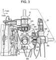
- FIG. 3 is a perspective view of the tube forming apparatus of the present invention taken from the rear end of the apparatus and illustrating a core tube adjustment system;
- FIG. 4 A is another perspective view of the tube forming apparatus of FIG. 3 ;
- FIG. 4 B is another perspective view of the tube forming apparatus of FIG. 3 ;
- FIG. 5 A is a schematic drawing of a computer screen display of tube wall thickness measurements before adjustment
- FIG. 5 B is a schematic drawing of a computer screen display of tube wall thickness measurements after adjustment
- FIG. 6 is a graph showing tube wall thickness and adjustments as a function of time
- FIG. 7 is a graph showing tube wall concentricity and adjustments as a function of time
- FIG. 8 is a display showing tube wall concentricity, tube wall eccentricity, and tube wall thickness measurements
- FIG. 9 is a cross sectional view of the axial displacement device for axially moving the core tube assembly.
- FIG. 10 is a perspective view of the axial displacement device of FIG. 9 .
- a tube forming apparatus of the present invention for multi-dimensional controlled forming of polymeric tube is generally designated by the numeral 10 .
- the tube forming apparatus 10 includes a housing 12 that extends around a longitudinal axis L and between a rear end 12 A and a discharge end 12 B thereof.
- the housing 12 has an inside surface 12 F (best seen in FIG. 2 C ) that extends between the rear end 12 A and the discharge end 12 B.
- the inside surface 12 F forms an interior area 12 C inside the housing 12 .
- a die 18 is arranged proximate to the discharge end 12 B of the housing 12 , as described further herein.
- the tube forming apparatus 10 includes a core tube assembly 14 that is positioned in the interior area 12 C of the housing 12 .
- the tube forming apparatus 10 includes a mandrel 17 that is disposed in the interior area 12 C.
- the mandrel 17 surrounds a portion of the core tube assembly 14 and is fixedly secured to the rear end 12 A of the housing 12 .
- a diverter tip 16 is arranged to a portion of the core tube assembly 14 , as described further herein.
- a hollow tube 20 (e.g., having a circular cross section) is shown being discharged from a portion of the die 18 adjacent to the diverter tip 16 , as described further herein.
- tube forming apparatus 10 has utility in forming hollow tubes with a circular cross section
- the present invention is not limited in this regard as the tube forming apparatus 10 may be employed to form other geometrically shaped products and tubes such as tubes with rectilinear, oval, triangular and star shaped cross sections and tubes with ribs or protrusions thereon.
- a core tube adjustment system 30 is mounted proximate the rear end 12 A of the housing 12 .
- the core tube adjustment system 30 includes: (a) an axial displacement device 40 configured to axially position the core tube assembly 14 for modulating wall thickness of the tube 20 being discharged from the housing 12 ; and (b) an angular displacement device 50 configured to modulate (e.g., tilt, incline, slant or slope relative to the longitudinal axis L sweeping an angle that forms a conical shaped area) a portion (i.e., an inner core tube 14 B, as shown in FIGS. 2 B and 2 C ) of the core tube assembly 14 , relative to the longitudinal axis L, as described further herein.
- the angular displacement device 50 has utility in modulating concentricity of the tube 20 being discharged from the die 18 .
- the angular displacement device 50 includes a bearing 60 that is in communication with a portion of the core tube assembly 14 , as described further herein.
- the tube forming apparatus 10 includes a control system 75 for automatic control of the thickness, inside diameter, outside diameter and concentricity of the tube 20 .
- the tube forming apparatus 10 includes sensor system 70 that includes: (a) a tube size sensor system 71 configured to measure wall thickness of the tube 20 , inside diameter of the tube 20 and/or outside diameter of the tube 20 and to generate tube size signals 71 F (e.g., tube wall thickness and diameter signals); and (b) a tube concentricity sensor system 72 configured to measure concentricity of the tube 20 and to generate tube concentricity signals 72 F.
- the control system 75 is in communication with the core tube adjustment system 30 and the sensor system 70 .
- the control system 75 includes a computer processor 75 P configured with executable software 76 that includes algorithms that analyze and control the wall thickness and the concentricity of the tube 20 .
- the computer processor 75 P is configured to receive the tube size signals 71 F and/or the concentricity signals 72 F.
- the executable software 76 is configured to analyze the tube size signals 71 F and/or the concentricity signals 72 F and is configured to control the tube adjustment system 30 to automatically modulate wall thickness and concentricity of the tube 20 .
- a plurality of displays 75 D 1 , 75 D 2 are in communication with the computer processor 75 P.
- the tube size sensor system 71 and/or the tube concentricity sensor system 72 employ X-ray gauges, ultrasound gauges, nuclear gauges and/or other suitable gauges.
- the core tube assembly 14 includes an exterior core tube 14 A with an inner core tube 14 B positioned partially therein.
- the exterior core tube 14 A extends between a pivot end 14 M and a tip engagement end 14 C thereof.
- the inner core tube 14 B has an exterior surface 14 F and extends between a first inner tube end 14 G and a second inner tube end 14 H thereof.
- the first inner tube end 14 G of the inner core tube 14 B is disposed in the exterior core tube 14 A and the second inner tube end 14 H of the inner core tube 14 B extends out of the exterior core tube 14 A proximate the rear end 12 A (see FIG. 2 A ) of the housing 12 (see FIG. 2 A ).
- the tube forming apparatus 10 includes the diverter tip 16 mounted in (e.g., threaded into, welded to or secured via another suitable fixed connection) and extending outwardly from the first inner tube end 14 G of the inner core tube 14 B.
- the inner core tube 14 B is in fixed axial relation to the exterior core tube 14 A between the diverter tip 16 and a locking assembly 39 . Details of the diverter tip 16 and the locking assembly are described further herein with respect to FIG. 2 C and FIG. 2 B , respectively.
- the diverter tip 16 has a tapered exterior tip-surface 16 F thereon.
- the tapered exterior tip-surface 16 F is generally conical and tapers radially inward from the exterior core tube 14 A and axially away from the first inner tube end 14 G of the inner core tube 14 B.
- the diverter tip 16 extends into the die 18 .
- the die 18 has an inner die-surface 18 F that is generally conical and is complementary in shape to the tapered exterior tip-surface 16 F of the diverter tip 16 .
- a die opening G 1 is formed between the inner die-surface 18 F and the exterior tip-surface 16 F.
- the diverter tip 16 includes a convex spherical exterior surface 16 C that extends from the diverter tip 16 , radially and axially inward toward the inner core tube 14 B from a radially outermost portion of the tapered exterior tip surface 16 F.
- the tip engagement end 14 C the exterior core tube 14 A has a concave spherical engagement surface that is complementary in shape to the convex spherical exterior surface 16 C of the diverter tip 16 .
- the convex spherical exterior surface 16 C slidingly engages the stationary tip engagement surface 14 C of the exterior core tube 14 A in response to modulation of the inner core tube 14 B relative to the stationary exterior core tube 14 A as shown and described further herein with regard to FIG. 2 E .
- a flow passage FP is formed between the mandrel 17 and the inside surface 12 F of the housing 12 .
- the flow passage FP extends between the tapered exterior tip-surface 16 F and the inner die-surface 18 F and terminates at the die opening G 1 where the tube 20 is formed and is discharged from the tube forming apparatus 10 .
- the locking assembly 39 includes a bushing 31 and a lock nut 32 that are threaded onto the inner core tube 14 B such that the inner core tube 14 B engages an axial face 31 M of the bushing 31 and the lock nut 32 engages and axially secures the bushing 31 to the inner core tube 14 B.
- the axial face 31 M of the bushing 31 has a concave spherical contour and the pivot end 14 M of the exterior core tube 14 A has a convex spherical contour that is complementary in shape to the concave spherical contour of the axial face 31 M of the bushing 31 .
- the axial face 31 M is in sliding engagement with the stationary pivot end 14 M of the exterior core tube 14 A, for example during modulation of the inner core tube 14 B caused by the angular displacement device 50 as shown and described further herein with respect to FIG. 2 E .
- the axial displacement device 40 includes an L-shaped collar 41 that has a longitudinal leg 41 L that extends parallel to the longitudinal axis L and has internal threads 41 T (e.g., female threads) formed therein.
- a radial leg 41 R extends radially outward from the longitudinal leg 41 L.
- the L-shaped collar 41 is threaded on to a drive thread 14 ET (e.g., an external threaded portion) on the exterior surface 14 E of the exterior core tube 14 A.
- a thrust bearing 38 is disposed between the radially leg 41 R and the housing 12 to support thrust loads.
- the thrust bearing 38 is disposed between and engages the radial leg 41 R and a cover plate 35 A secured to the rear end 12 A of the housing 12 .
- the axial displacement device 40 includes a drive thread 14 ET is formed on the exterior surface 14 E of the exterior core tube 14 A and a gear arrangement 37 (see FIGS. 9 and 10 for further cross section and perspective views, respectively) is in communication with the drive thread 14 ET such that operation of the gear arrangement 37 causes axial movement of the core tube assembly 14 .
- FIG. 9 illustrates the gear arrangement 37 which includes a bull gear 37 A (e.g., main gear) that is keyed to the L-shaped collar 41 with keys 41 K.
- the bull gear 37 A is mounted between the cover plate 35 A and an end plate 35 B.
- FIG. 9 illustrates the gear arrangement 37 which includes a bull gear 37 A (e.g., main gear) that is keyed to the L-shaped collar 41 with keys 41 K.
- the bull gear 37 A is driven by a pinion gear 37 B that is rotatably mounted in a housing 37 H.
- the pinion gear 37 B is rotated by drive shaft 92 A of a drive unit 92 , such as a servo motor. Rotation of the bull gear 37 A causes axial movement of the core tube assembly 14 .
- the axial displacement device 40 is configured to accomplish the axially positioning the core tube assembly 14 during operation of the tube forming apparatus 10 .
- the angular displacement device 50 includes a spherical bearing 60 that has an outer member 62 positioned around an inner member 64 .
- the outer member 62 has a cylindrical outer surface 62 E and a concave spherical inner bearing surface 62 F.
- the inner member 64 has convex spherical outer bearing surface 64 F and a cylindrical inner surface 64 E.
- the exterior surface 14 F of the inner core tube 14 B is in axial sliding engagement with the cylindrical inner surface 64 E of the inner member 64 , for example during adjustment of the axial position of the core tube assembly 14 using the axial displacement device 40 (see FIG. 2 B ).
- the angular displacement device 50 includes a first actuator 51 that is configured to modulate the inner core tube 14 B in a first radial direction (Y-axis).
- the angular displacement device 50 includes a second actuator 52 that is configured to modulate the inner core tube 14 B in a second radial direction (X-axis) that is perpendicular to the first radial direction (Y-axis), such that cooperation of the first actuator 51 and the second actuator 52 enables modulating of the inner core tube 14 B in a wide range of angular directions (e.g., in a conical envelope) relative to the longitudinal axis L.
- the first actuator 51 is in fixed relation to the housing 12 except that the first actuator 51 is moveable relative to the housing 12 in the second radial direction (X-axis); and the second actuator 52 is in fixed relation to the housing 12 except that the second actuator 52 is moveable relative to the housing 12 in the first radial direction (Y-axis).
- the first actuator 51 includes a first servo motor 90 Y that has an actuator rod 51 R that is in engagement with an exterior surface 53 X (i.e., on an X-axis plane) of a modulation collar 53 .
- the second actuator 52 includes a second servo motor 90 X that has an actuator rod 52 R that is in engagement with an exterior surface 53 Y (i.e., on a Y-axis plane) of the modulation collar 53 .
- the modulation collar 53 has an interior cylindrical surface 53 F that surrounds and engages the cylindrical outer surface 62 E of the outer member 62 of the spherical bearing 60 .
- the angular displacement device 50 includes a first linear bearing 51 B disposed between the housing 12 (see FIG. 4 A ) and the first actuator 51 to facilitate movement of the first actuator 51 relative to the housing 12 in the second radial direction (X-axis).
- a second linear bearing 52 B is disposed between the housing 12 (see FIG. 4 A ) and the second actuator 52 to facilitate movement of the second actuator 52 relative to the housing 12 (see FIG. 4 A ) in the first radial direction (Y-axis).
- the inner core tube 14 B is modulatable at an angle ⁇ of up to 5 degree relative to a reference line RL that is parallel to the longitudinal axis L, for a total included angle of 10 degrees between opposing maximum modulation angles ⁇ (i.e., the included angle equals 2 times ⁇ ).
- the modulation of the inner core tube 14 B over the angle ⁇ results in adjustment of the diverter tip 16 in the die 18 to adjust the concentricity of the die opening G 1 .
- the angular displacement device 50 is configured to accomplish the modulating of the inner core tube 14 B from a position axially outward from the rear end 12 A of the housing 12 during operation of the tube forming apparatus 10 . As shown in FIG.
- the core tube assembly 14 is shown in a neutral position with the inner core tube 14 B shown coaxial with the exterior core tube 14 A and the longitudinal axis L.
- the actuator rod 51 R is in a position to engage the exterior surface 53 X of the modulation collar 53 at a reference line R 1 .
- the extension of the actuator rod 51 R by a stroke length L 10 results in the actuator rod 51 R engaging the exterior surface 53 X at a reference line RE which is a distance equal to the stroke length L 10 away from the reference line R 1 .
- the extension of the actuator rod 51 R by the stroke length L 10 also results in modulation of the inner core tube 14 B by the angle ⁇ .
- the modulation of the inner core tube 14 B results in adjustment of the magnitude of the die opening as indicated by element numbers G 1 and G 2 on FIG. 2 E .
- a wear resistant coating is applied to the inner die-surface 18 F, the exterior tip-surface 16 F and the axial face 31 M of the inner bushing 31 .
- the wear resistant coating is a chromium based material.
- the mandrel assembly 17 has a tapered area configured to facilitate installation and removal of the mandrel assembly 17 to and from the housing 12 .
- FIG. 5 A illustrates a reproduction of a screen image 200 that appears on one or more of the displays 75 D 1 , 75 D 2 shown in FIG. 2 A .
- the screen image 200 illustrates the wall thickness of the tube 20 as measured by the tube size sensor system 71 of the sensor system 70 shown in FIG. 2 A .
- the tube size sensor system 71 measures the wall thickness “T” of the tube at eight distinct points T 1 , T 2 , T 3 , T 4 , T 5 , T 6 , T 7 and T 8 , equidistantly spaced around the circumference of the tube 20 discharged from the die opening G 1 .
- the tube 20 discharged from the die opening G 1 is strung through a gauge (e.g., x-ray gauge, ultrasound gage) to measure the wall thickness at the eight distinct points T 1 , T 2 , T 3 , T 4 , T 5 , T 6 , T 7 , and T 8 , for example, during operation of the tube forming apparatus 10 .
- a gauge e.g., x-ray gauge, ultrasound gage
- FIG. 5 A thickness T 2 is below a minimum wall thickness set by the user or operator and thickness T 6 is above a maximum wall thickness set by the user or operator.
- a computer processor 75 P (shown in FIG. 2 A ) analyzes the tube wall thickness signals 75 F and controls the tube adjustment system 30 to modulate the wall thickness of the tube 20 discharged from the die opening G 1 .
- FIG. 5 B depicts the screen image 200 ′ illustrating the wall thickness of the tube 20 at the eight distinct points T 1 , T 2 , T 3 , T 4 , T 5 , T 6 , T 7 and T 8 after the tube adjustment system 30 modulates the wall thickness of the tube 20 .
- the screen image 200 ′ depicted in FIG. 5 B shows the thickness measurements at all eight points T 1 , T 2 , T 3 , T 4 , T 5 , T 6 , T 7 and T 8 are within acceptable ranges.
- FIG. 6 is a graph 220 that depicts the wall thickness T of the tube 20 as a function of time as the tube adjustment system 30 automatically adjusts the thicknesses T of the wall thickness of the tube 20 , as discussed herein with reference to FIG. 5 A to FIG. 5 B .
- the graph 220 designates time on an X coordinate axis which is designated as element number 222 on the graph 220 .
- the graph 220 designates wall thickness T of the tube 20 on a left side Y coordinate axis which is marked as element number 224 on the graph 220 .
- the graph 220 designates adjustments made by the tube adjustment system 30 (see FIG. 2 A ) on a right side Y coordinate axis which is marked as element number 225 on the graph 220 .
- the present invention is not limited in this regard as more than eight points or less than eight points may be measured by the sensor system 70 .
- a plot 228 depicts the wall thickness measurement point T 6 as a function of time and a plot 226 depicts the wall thickness measurement point T 2 as a function of time, as depicted in FIG. 5 A .
- the graph 220 also includes a plot 229 (depicted as a dotted line in FIG. 6 ) of the number of adjustments as a function of time.
- the graph 220 also includes a horizontal line 223 that designates the target nominal wall thickness (e.g., shown in the graph 220 as being about 0.054 inches).
- the executable software 76 in the computer processor 75 P automatically initiates adjustments via the tube adjustment system 30 when the wall thickness of the tube 20 exceeds a target wall nominal thickness 223 (see FIG. 6 ) for a predetermined length of time.
- the adjustments automatically modulate the thickness of the wall of the tube 20 at measurement point T 6 based upon the tube size signals 71 F processed by the computer processor 75 P decreases, approaching the target wall nominal thickness 223 shown in FIG. 6 .
- the thickness T of the tube 20 at measurement point T 6 decreases, the thickness of the tube 20 at the measurement point T 2 increases accordingly. As shown in FIG.
- both the plot 228 of the thickness of the tube 20 at the measurement point T 6 and the plot 226 of the thickness of the tube 20 at measurement point T 2 approach the target wall nominal thickness 223 in response to adjustments 229 by the tube adjustment system 30 .
- the adjustments 229 are automatically initiated at an appropriate time as marked on the graph 220 .
- the tube adjustment system 30 automatically decreases the thickness of the tube 20 at measurement point T 6 and increases the thickness of the tube measurement point T 2 .
- Each time the tube adjustment system 30 adjusts the thickness of the tube at measurement points T 6 and T 2 and the measurements are compared to the target wall nominal thickness 223 .
- FIG. 7 is a graph 230 that depicts the concentricity of the tube 20 on the left side Y-axis 232 discharged from the die opening G 1 over time shown on the X-axis 234 .
- the graph 230 designates adjustments by the motors 90 X and 90 Y of the angular displacement device 50 (see FIG. 2 A ) on a right side Y coordinate axis, which is marked as element number 225 on the graph 230 .
- the tube 20 discharged from the die opening G 1 has a concentricity 236 of approximately 70%, due to the tube thickness being significantly less than the target wall nominal thickness 223 at one thickness measurement point T 2 and the tube thickness being significantly greater than the target wall nominal thickness 223 at another thickness measurement point T 6 .
- Adjustments by the tube adjustment system 30 result in an increase in concentricity 236 of the tube 20 discharged from the die opening G 1 .
- An initial concentricity of around 70-80% is expected.
- the automatic adjustment by the computer processor 75 P in cooperation with the tube adjustment system 30 maximizes the concentricity 236 of the tube 20 discharged from the die opening G 1 and minimizes the eccentricity 237 (depicted in FIG. 8 ) of the tube 20 discharged from the die opening G 1 .
- the computer processor 75 P of the tube forming apparatus 10 continues to monitor the thickness and concentricity of the tube 20 discharged from the die opening G 1 and continues to send the tube size signals 71 F and/or concentricity signals 72 F when necessary.
- the computer processor 75 P accounts for variation over as the tube 20 exits the die opening G 1 , including variation based on day or night limitations, and variations required to correct for gum space adjustment.
- FIG. 8 illustrates a reproduction of a representative display 75 D 1 ′ as shown in FIG. 2 A .
- the depicted display 75 D 1 ′ has a screen image 200 ′′ that illustrates the thickness of the tube 20 as measured by the tube size sensor system 71 of the sensor system 70 shown in FIG. 2 A .
- the thickness measurements at all points T 1 , T 2 , T 3 , T 4 , T 5 , T 6 , T 7 , and T 8 are all within an acceptable range.
- the computer processor 75 P adjusts the servo motors 90 X, 90 Y (see FIG.
- the representative display 75 D 1 ′ depicts the thickness measurements at each point, the concentricity 236 , and the eccentricity 237 in real time to allow an algorithm contained in the computer processor 75 P or a user to adjust the axial displacement device 40 and/or the angular displacement device 50 (as depicted in FIGS.
Landscapes
- Engineering & Computer Science (AREA)
- Mechanical Engineering (AREA)
- Manufacturing & Machinery (AREA)
- Extrusion Moulding Of Plastics Or The Like (AREA)
Abstract
Description
Claims (15)
Priority Applications (1)
| Application Number | Priority Date | Filing Date | Title |
|---|---|---|---|
| US17/065,633 US11577442B2 (en) | 2019-10-09 | 2020-10-08 | Polymeric tube forming apparatus with a multi-dimensional control system |
Applications Claiming Priority (2)
| Application Number | Priority Date | Filing Date | Title |
|---|---|---|---|
| US201962912898P | 2019-10-09 | 2019-10-09 | |
| US17/065,633 US11577442B2 (en) | 2019-10-09 | 2020-10-08 | Polymeric tube forming apparatus with a multi-dimensional control system |
Publications (2)
| Publication Number | Publication Date |
|---|---|
| US20210107203A1 US20210107203A1 (en) | 2021-04-15 |
| US11577442B2 true US11577442B2 (en) | 2023-02-14 |
Family
ID=72811646
Family Applications (1)
| Application Number | Title | Priority Date | Filing Date |
|---|---|---|---|
| US17/065,633 Active 2040-12-09 US11577442B2 (en) | 2019-10-09 | 2020-10-08 | Polymeric tube forming apparatus with a multi-dimensional control system |
Country Status (7)
| Country | Link |
|---|---|
| US (1) | US11577442B2 (en) |
| EP (3) | EP4159406A1 (en) |
| JP (1) | JP7719597B2 (en) |
| KR (1) | KR20210042833A (en) |
| CN (1) | CN112643995B (en) |
| CA (1) | CA3095514C (en) |
| MX (1) | MX2020010637A (en) |
Families Citing this family (2)
| Publication number | Priority date | Publication date | Assignee | Title |
|---|---|---|---|---|
| JP7741839B2 (en) * | 2023-04-19 | 2025-09-18 | 中田エンヂニアリング株式会社 | Extrusion Head |
| CN119747421A (en) * | 2025-03-06 | 2025-04-04 | 龙口市龙蓬精密铜管有限公司 | Special-shaped copper pipe stretching die capable of being positioned rapidly |
Citations (10)
| Publication number | Priority date | Publication date | Assignee | Title |
|---|---|---|---|---|
| US3209404A (en) | 1961-08-03 | 1965-10-05 | Hagen Norbert | Extruder |
| US3221372A (en) * | 1963-09-16 | 1965-12-07 | Johnson & Johnson | Apparatus for extruding collagen fibrils |
| US3386132A (en) * | 1965-10-22 | 1968-06-04 | Hoover Ball & Bearing Co | Extrusion apparatus |
| US3923439A (en) * | 1972-10-10 | 1975-12-02 | Western Electric Co | System for controlling the eccentricity of an extruded article |
| US5120212A (en) | 1989-11-02 | 1992-06-09 | Krauss-Maffei Aktiengesellschaft | Thickness-adjusting system for tubing extruder |
| US5206032A (en) * | 1990-06-29 | 1993-04-27 | Krupp Kautex Maschinenbau Gmbh | Apparatus for producing a preform for the manufacture of a hollow body from thermoplastic material |
| WO1997039872A1 (en) | 1996-04-22 | 1997-10-30 | Greif Bros. Corporation | Process for preparing thermoplastic polyolefin resin articles of reduced hydrocarbon permeability |
| WO2002026470A1 (en) | 2000-09-28 | 2002-04-04 | Genca Corporation | Crosshead with accurate adjustment for uniform dispersion of extrudate |
| DE102008061286A1 (en) | 2008-12-11 | 2010-06-17 | Troester Gmbh & Co. Kg | Extrusion device for manufacturing tubular hollow bodies i.e. tubes, or casings from polymer materials, has annular passage adjustable by automatic adjusting unit lying against area of spindle sleeve, where area is turned to extruder nozzle |
| CN205767428U (en) | 2016-07-20 | 2016-12-07 | 苏州同大机械有限公司 | The double-deck water conservancy diversion storing type die head device of blow moulding machine |
Family Cites Families (11)
| Publication number | Priority date | Publication date | Assignee | Title |
|---|---|---|---|---|
| NL7014565A (en) * | 1970-10-05 | 1972-04-07 | ||
| US4882104A (en) * | 1987-04-03 | 1989-11-21 | Cincinnati Milacron, Inc. | Method of controlling the thickness of an extruded plastic article |
| US4946364A (en) * | 1989-05-31 | 1990-08-07 | Rcm, Ltd., Rubber Consulting & Machinery | Apparatus for manufacturing reinforced polymeric tubing |
| JPH05116201A (en) * | 1991-10-25 | 1993-05-14 | Sekisui Chem Co Ltd | Synthetic resin pipe extrusion molding equipment |
| JPH10202724A (en) * | 1997-01-21 | 1998-08-04 | Sekisui Chem Co Ltd | Automatic thickness adjustment device in extrusion equipment |
| NL1012032C2 (en) * | 1999-03-05 | 2000-09-06 | Wavin Bv | Method for manufacturing a tube of biaxially oriented thermoplastic plastic material. |
| CN203198226U (en) * | 2013-02-04 | 2013-09-18 | 惠升管业有限公司 | Pipe extrusion die |
| CN205238540U (en) * | 2015-12-23 | 2016-05-18 | 台州奥博管业有限公司 | Pipe extruder wall thickness automated inspection governing system |
| CN106079370B (en) * | 2016-06-22 | 2018-06-26 | 湖北工业大学 | Size detecting system and detection method are squeezed out for pvc pipe |
| JP6581633B2 (en) * | 2017-09-12 | 2019-09-25 | 株式会社協成 | Manufacturing method of resin-coated steel pipe |
| CN108016020B (en) * | 2017-12-12 | 2023-10-24 | 河北天昱恒科技有限公司 | Automatic detection device for plastic pipe |
-
2020
- 2020-10-06 CA CA3095514A patent/CA3095514C/en active Active
- 2020-10-06 JP JP2020168843A patent/JP7719597B2/en active Active
- 2020-10-08 EP EP22206171.5A patent/EP4159406A1/en active Pending
- 2020-10-08 KR KR1020200130234A patent/KR20210042833A/en active Pending
- 2020-10-08 EP EP22206160.8A patent/EP4159405B1/en active Active
- 2020-10-08 MX MX2020010637A patent/MX2020010637A/en unknown
- 2020-10-08 US US17/065,633 patent/US11577442B2/en active Active
- 2020-10-08 EP EP20200703.5A patent/EP3804954B1/en active Active
- 2020-10-09 CN CN202011072626.5A patent/CN112643995B/en active Active
Patent Citations (10)
| Publication number | Priority date | Publication date | Assignee | Title |
|---|---|---|---|---|
| US3209404A (en) | 1961-08-03 | 1965-10-05 | Hagen Norbert | Extruder |
| US3221372A (en) * | 1963-09-16 | 1965-12-07 | Johnson & Johnson | Apparatus for extruding collagen fibrils |
| US3386132A (en) * | 1965-10-22 | 1968-06-04 | Hoover Ball & Bearing Co | Extrusion apparatus |
| US3923439A (en) * | 1972-10-10 | 1975-12-02 | Western Electric Co | System for controlling the eccentricity of an extruded article |
| US5120212A (en) | 1989-11-02 | 1992-06-09 | Krauss-Maffei Aktiengesellschaft | Thickness-adjusting system for tubing extruder |
| US5206032A (en) * | 1990-06-29 | 1993-04-27 | Krupp Kautex Maschinenbau Gmbh | Apparatus for producing a preform for the manufacture of a hollow body from thermoplastic material |
| WO1997039872A1 (en) | 1996-04-22 | 1997-10-30 | Greif Bros. Corporation | Process for preparing thermoplastic polyolefin resin articles of reduced hydrocarbon permeability |
| WO2002026470A1 (en) | 2000-09-28 | 2002-04-04 | Genca Corporation | Crosshead with accurate adjustment for uniform dispersion of extrudate |
| DE102008061286A1 (en) | 2008-12-11 | 2010-06-17 | Troester Gmbh & Co. Kg | Extrusion device for manufacturing tubular hollow bodies i.e. tubes, or casings from polymer materials, has annular passage adjustable by automatic adjusting unit lying against area of spindle sleeve, where area is turned to extruder nozzle |
| CN205767428U (en) | 2016-07-20 | 2016-12-07 | 苏州同大机械有限公司 | The double-deck water conservancy diversion storing type die head device of blow moulding machine |
Non-Patent Citations (2)
| Title |
|---|
| CN Office Action issued in corresponding CN Application No. 202011072626.5, dated Aug. 10, 2022. pp. 1-11. |
| Extended European Search Report issued in corresponding EP Application No. 20200703.5, dated Mar. 5, 2021, pp. 1-8. |
Also Published As
| Publication number | Publication date |
|---|---|
| EP4159405A1 (en) | 2023-04-05 |
| EP4159405B1 (en) | 2024-05-15 |
| CN112643995B (en) | 2023-07-28 |
| KR20210042833A (en) | 2021-04-20 |
| CA3095514C (en) | 2025-03-11 |
| JP2021075048A (en) | 2021-05-20 |
| MX2020010637A (en) | 2021-08-19 |
| EP3804954A1 (en) | 2021-04-14 |
| JP7719597B2 (en) | 2025-08-06 |
| EP3804954B1 (en) | 2023-11-29 |
| CN112643995A (en) | 2021-04-13 |
| CA3095514A1 (en) | 2021-04-09 |
| EP4159406A1 (en) | 2023-04-05 |
| US20210107203A1 (en) | 2021-04-15 |
Similar Documents
| Publication | Publication Date | Title |
|---|---|---|
| US11577442B2 (en) | Polymeric tube forming apparatus with a multi-dimensional control system | |
| US20230018826A1 (en) | Apparatus and method to adjust the thickness profile in the production of blown films | |
| CN106413985B (en) | Method for mounting end pieces for fixing flexible cylindrical tubes and device for carrying out said method | |
| US11718009B2 (en) | Concentricity adjustment sleeve | |
| US20220055159A1 (en) | Flange fitting for tubular structures | |
| EP3999308B1 (en) | Method and device for measuring a tubular strand | |
| EP0429862B1 (en) | Centering apparatus for a tube extruder head | |
| KR102522385B1 (en) | film forming device | |
| WO2020072322A1 (en) | Adjustable extruder die retaining assembly and method | |
| CN108698781A (en) | Management method for device for winding up and corresponding equipment | |
| EP3552799B1 (en) | Tool head for a hollow profile extruder | |
| DE102014208911B4 (en) | Gear pump and gear pump actuation method | |
| EP1736297A1 (en) | Controllable gas cooling ring with rectifying unit and method for controlling and/or regulating a gas cooling ring during the manufacture of blown thermoplastic films | |
| JPH07155949A (en) | Spiral steel pipe automatic welding method | |
| DE1552359A1 (en) | Measuring device on peeling machines for bars or tubes | |
| JP2024507062A (en) | Method and system for forming tubular or frustoconical segments | |
| US3492694A (en) | Radial extrusion die | |
| EP2336566B1 (en) | Rolling bearing arrangement | |
| JPH06262122A (en) | Metal plate resin coating equipment | |
| US20090272164A1 (en) | Tube making machine with diameter control and method | |
| CA2659953A1 (en) | Tube making machine with diameter control and method | |
| CN121475048A (en) | A steel pipe outer diameter detection device | |
| DE19805602A1 (en) | Method of measuring and setting gauge openings formed by drive and/or non-driven rollers, e.g. for rolling systems for producing rolled goods | |
| GB1598855A (en) | Extrusion of plastics pipes | |
| JPS629945A (en) | Winding material of strip stock for flexible pipe at flexible-pipe making apparatus |
Legal Events
| Date | Code | Title | Description |
|---|---|---|---|
| FEPP | Fee payment procedure |
Free format text: ENTITY STATUS SET TO UNDISCOUNTED (ORIGINAL EVENT CODE: BIG.); ENTITY STATUS OF PATENT OWNER: LARGE ENTITY |
|
| STPP | Information on status: patent application and granting procedure in general |
Free format text: APPLICATION DISPATCHED FROM PREEXAM, NOT YET DOCKETED |
|
| STPP | Information on status: patent application and granting procedure in general |
Free format text: DOCKETED NEW CASE - READY FOR EXAMINATION |
|
| AS | Assignment |
Owner name: BANK OF MONTREAL, AS COLLATERAL AGENT, CANADA Free format text: NOTICE OF GRANT OF SECURITY INTEREST IN PATENTS;ASSIGNORS:DAVIS-STANDARD, LLC;THERMOFORMING SYSTEMS, LLC;REEL/FRAME:058495/0515 Effective date: 20211210 |
|
| STPP | Information on status: patent application and granting procedure in general |
Free format text: NON FINAL ACTION MAILED |
|
| AS | Assignment |
Owner name: DAVIS-STANDARD, LLC, CONNECTICUT Free format text: ASSIGNMENT OF ASSIGNORS INTEREST;ASSIGNORS:CHRISTIANO, JOHN P.;BIRON, CHAD ALLEN;MACGREGOR, ALEXANDRE;AND OTHERS;SIGNING DATES FROM 20200713 TO 20200811;REEL/FRAME:059595/0171 |
|
| STPP | Information on status: patent application and granting procedure in general |
Free format text: RESPONSE TO NON-FINAL OFFICE ACTION ENTERED AND FORWARDED TO EXAMINER |
|
| STPP | Information on status: patent application and granting procedure in general |
Free format text: NOTICE OF ALLOWANCE MAILED -- APPLICATION RECEIVED IN OFFICE OF PUBLICATIONS |
|
| STPP | Information on status: patent application and granting procedure in general |
Free format text: NOTICE OF ALLOWANCE MAILED -- APPLICATION RECEIVED IN OFFICE OF PUBLICATIONS |
|
| STPP | Information on status: patent application and granting procedure in general |
Free format text: NOTICE OF ALLOWANCE MAILED -- APPLICATION RECEIVED IN OFFICE OF PUBLICATIONS |
|
| STPP | Information on status: patent application and granting procedure in general |
Free format text: PUBLICATIONS -- ISSUE FEE PAYMENT VERIFIED |
|
| STCF | Information on status: patent grant |
Free format text: PATENTED CASE |
|
| AS | Assignment |
Owner name: WELLS FARGO BANK, NATIONAL ASSOCIATION, AS COLLATERAL AGENT, TEXAS Free format text: SECURITY INTEREST;ASSIGNOR:DAVIS-STANDARD, LLC;REEL/FRAME:066308/0392 Effective date: 20240131 |
|
| AS | Assignment |
Owner name: THERMOFORMING SYSTEMS, LLC, WASHINGTON Free format text: TERMINATION AND RELEASE OF SECURITY INTEREST IN PATENTS (REEL/FRAME 058495/0515);ASSIGNOR:BANK OF MONTREAL, AS COLLATERAL AGENT;REEL/FRAME:066627/0842 Effective date: 20240131 Owner name: DAVIS-STANDARD, LLC, CONNECTICUT Free format text: TERMINATION AND RELEASE OF SECURITY INTEREST IN PATENTS (REEL/FRAME 058495/0515);ASSIGNOR:BANK OF MONTREAL, AS COLLATERAL AGENT;REEL/FRAME:066627/0842 Effective date: 20240131 |
|
| AS | Assignment |
Owner name: DEUTSCHE BANK AG, NEW YORK BRANCH, AS COLLATERAL AGENT, NEW YORK Free format text: SECURITY INTEREST;ASSIGNOR:DAVIS-STANDARD, LLC;REEL/FRAME:071297/0766 Effective date: 20250411 |