US11569724B2 - Faraday based pallet generator for device charging - Google Patents
Faraday based pallet generator for device charging Download PDFInfo
- Publication number
- US11569724B2 US11569724B2 US16/939,417 US202016939417A US11569724B2 US 11569724 B2 US11569724 B2 US 11569724B2 US 202016939417 A US202016939417 A US 202016939417A US 11569724 B2 US11569724 B2 US 11569724B2
- Authority
- US
- United States
- Prior art keywords
- upper platform
- dampener
- guide shaft
- platform
- disposed
- Prior art date
- Legal status (The legal status is an assumption and is not a legal conclusion. Google has not performed a legal analysis and makes no representation as to the accuracy of the status listed.)
- Active, expires
Links
- 230000006835 compression Effects 0.000 claims abstract description 36
- 238000007906 compression Methods 0.000 claims abstract description 36
- 238000003860 storage Methods 0.000 claims abstract description 12
- 230000035939 shock Effects 0.000 claims description 4
- 230000033001 locomotion Effects 0.000 description 25
- 230000007704 transition Effects 0.000 description 20
- 239000011343 solid material Substances 0.000 description 10
- 239000000463 material Substances 0.000 description 8
- 230000000694 effects Effects 0.000 description 4
- 239000003990 capacitor Substances 0.000 description 3
- 239000013078 crystal Substances 0.000 description 2
- 230000026058 directional locomotion Effects 0.000 description 2
- 238000009826 distribution Methods 0.000 description 2
- 239000006260 foam Substances 0.000 description 2
- 230000001939 inductive effect Effects 0.000 description 2
- 238000000034 method Methods 0.000 description 2
- 239000010453 quartz Substances 0.000 description 2
- VYPSYNLAJGMNEJ-UHFFFAOYSA-N silicon dioxide Inorganic materials O=[Si]=O VYPSYNLAJGMNEJ-UHFFFAOYSA-N 0.000 description 2
- 239000013589 supplement Substances 0.000 description 2
- 239000002023 wood Substances 0.000 description 2
- RYGMFSIKBFXOCR-UHFFFAOYSA-N Copper Chemical compound [Cu] RYGMFSIKBFXOCR-UHFFFAOYSA-N 0.000 description 1
- 239000002131 composite material Substances 0.000 description 1
- 229910052802 copper Inorganic materials 0.000 description 1
- 239000010949 copper Substances 0.000 description 1
- 238000013016 damping Methods 0.000 description 1
- 230000001934 delay Effects 0.000 description 1
- 230000001419 dependent effect Effects 0.000 description 1
- 230000005611 electricity Effects 0.000 description 1
- 238000005516 engineering process Methods 0.000 description 1
- 238000004519 manufacturing process Methods 0.000 description 1
- 239000002184 metal Substances 0.000 description 1
- 229910052751 metal Inorganic materials 0.000 description 1
- 238000012986 modification Methods 0.000 description 1
- 230000004048 modification Effects 0.000 description 1
- 238000012544 monitoring process Methods 0.000 description 1
- 239000004065 semiconductor Substances 0.000 description 1
Images


Classifications
-
- H—ELECTRICITY
- H02—GENERATION; CONVERSION OR DISTRIBUTION OF ELECTRIC POWER
- H02K—DYNAMO-ELECTRIC MACHINES
- H02K35/00—Generators with reciprocating, oscillating or vibrating coil system, magnet, armature or other part of the magnetic circuit
- H02K35/02—Generators with reciprocating, oscillating or vibrating coil system, magnet, armature or other part of the magnetic circuit with moving magnets and stationary coil systems
-
- H—ELECTRICITY
- H02—GENERATION; CONVERSION OR DISTRIBUTION OF ELECTRIC POWER
- H02K—DYNAMO-ELECTRIC MACHINES
- H02K44/00—Machines in which the dynamo-electric interaction between a plasma or flow of conductive liquid or of fluid-borne conductive or magnetic particles and a coil system or magnetic field converts energy of mass flow into electrical energy or vice versa
- H02K44/08—Magnetohydrodynamic [MHD] generators
- H02K44/16—Constructional details of the magnetic circuits
-
- H—ELECTRICITY
- H01—ELECTRIC ELEMENTS
- H01F—MAGNETS; INDUCTANCES; TRANSFORMERS; SELECTION OF MATERIALS FOR THEIR MAGNETIC PROPERTIES
- H01F7/00—Magnets
- H01F7/06—Electromagnets; Actuators including electromagnets
- H01F7/20—Electromagnets; Actuators including electromagnets without armatures
- H01F7/202—Electromagnets for high magnetic field strength
Definitions
- This disclosure relates generally to device charging, and in particular, to a faraday-based generator integrated into a pallet for device charging.
- IoT Internet of Things
- GPS Global Positioning System
- IoT sensors with enabled Global Positioning System (GPS) to monitor a position and status of a shipment (e.g., server equipment) during transit between an origin location and a destination location.
- the status of the shipment is monitored by collecting various data during transit that includes shock, vibration, tilt, temperature, humidity, and light readings.
- IoT sensors can experience a depletion of power reserves, thus resulting in missing data for the position and the status of the shipment.
- One aspect of an embodiment of the present invention discloses an apparatus for a faraday generator structure, the apparatus comprising the faraday generator structure disposed between an upper platform and a lower platform, wherein the faraday generator structure includes a magnet, a coil structure, and a guide shaft.
- the apparatus further comprising the magnet coupled to the guide shaft configured to pass through an inner aperture area of the ring structure during a compression and rebound of a dampener positioned between the upper platform and the lower platform, wherein a voltage is produced as the magnet passes through the inner aperture area of the ring structure.
- the apparatus further comprising the dampener configured to compress under an additional load applied to an existing load on a top surface of the upper platform.
- the apparatus further comprising the faraday generator structure configured to provide the voltage to an electrically coupled power storage unit.
- FIG. 1 depicts a pallet with multiple integrated faraday generator structures and electronic device, in accordance with an embodiment of the present invention.
- FIG. 2 depicts a pallet with multiple integrated faraday generator structures electrically coupled to an electronic device mounted to a shipment, in accordance with an embodiment of the present invention.
- FIG. 3 depicts a faraday generator structure positioned between an upper platform and a lower platform of a pallet, in accordance with an embodiment of the present invention.
- FIG. 4 A depicts a faraday generator structure with a load being applied to an upper platform of a pallet in an initial state, in accordance with an embodiment of the present invention.
- FIG. 4 B depicts a faraday generator structure with a damper in a compression transition state, in accordance with an embodiment of the present invention.
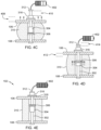
- FIG. 4 C depicts a faraday generator structure with a damper in a compressed state, in accordance with an embodiment of the present invention.
- FIG. 4 D depicts a faraday generator structure with a damper in a rebound transition state, in accordance with an embodiment of the present invention.
- FIG. 4 E depicts a faraday generator structure with a damper in a rebound state, in accordance with an embodiment of the present invention.
- FIG. 5 depicts a faraday generator structure utilizing a guide wire positioned between an upper platform and a lower platform of a pallet, in accordance with an embodiment of the present invention.
- FIG. 6 A depicts a faraday generator structure utilizing a guide wire with a load being applied to an upper platform of a pallet in an initial state, in accordance with an embodiment of the present invention.
- FIG. 6 B depicts a faraday generator structure utilizing a guide wire with a damper in a compression transition state, in accordance with an embodiment of the present invention.
- FIG. 6 C depicts a faraday generator structure utilizing a guide wire with a damper in a compressed state, in accordance with an embodiment of the present invention.
- FIG. 6 D depicts a faraday generator structure utilizing a guide wire with a damper in a rebound transition state, in accordance with an embodiment of the present invention.
- FIG. 6 E depicts a faraday generator structure utilizing a guide wire with a damper in a rebound state, in accordance with an embodiment of the present invention.
- Embodiments of the present invention provide a faraday generator structure integrated into a pallet, where the faraday generator structure is disposed between an upper platform and a lower platform of the pallet.
- the faraday generator structure utilizes additional forces (e.g., shock, vibration) applied to the upper platform which includes a previously applied load (i.e., shipment), to generate charge for one or more electronic devices associated with the pallet or the previously applied load.
- additional force e.g., shock, vibration
- energy is harvested and utilized to generate electrical power to charge a battery or capacitor for providing charge to the one or more electronic devices.
- terms such as “upper”, “lower”, “right”, “left”, “vertical”, “horizontal”, “top”, “bottom”, and derivatives thereof shall relate to the disclosed structures and methods, as oriented in the drawing figures.
- Terms such as “above”, “overlying”, “atop”, “on top”, “positioned on” or “positioned atop” mean that a first element, such as a first structure or first member, is present on a second element, such as a second structure or second member, wherein intervening elements, such as an interface structure may be present between the first element and the second element.
- direct contact means that a first element, such as a first structure, and a second element, such as a second structure, are connected without any intermediary conducting, insulating or semiconductor layers at the interface of the two elements.
- substantially, or substantially similar refer to instances in which the difference in length, height, or orientation convey no practical difference between the definite recitation (e.g. the phrase sans the substantially similar term), and the substantially similar variations.
- substantial (and its derivatives) denote a difference by a generally accepted engineering or manufacturing tolerance for similar devices, up to, for example, 10% deviation in value or 10° deviation in angle.
- FIG. 1 depicts a pallet with multiple integrated faraday generator structures and electronic device, in accordance with an embodiment of the present invention.
- Pallet 100 includes multiple faraday generator structures 102 electrically coupled to electronic device 104 , where each faraday generator structure 102 is positioned at various points of pallet 100 .
- Electronic device 104 is electrically coupled to the multiple faraday generator structures 102 utilizing one or more of cables, electrical contact pads, inductive charging, or other mediums for transferring electrical current.
- Pallet 100 includes upper platform 106 and lower platform 108 , where a lower surface of upper platform 106 is disposed on a top surface of supporting structures 110 and a lower surface of supporting structures 110 are disposed on a top surface of lower platform 108 .
- Supporting structure 110 can be a cushioning dampening material (e.g., foam, deformable plastic, corrugated cardboard), a solid material (e.g., wood, rigid plastic), or a combination of a solid material and a dampening material.
- a cushioning dampening material e.g., foam, deformable plastic, corrugated cardboard
- a solid material e.g., wood, rigid plastic
- electronic device 104 is integrated into pallet 100 , where electronic device 104 can be positioned at any location on pallet 100 such that electronic device 104 does not interfere with a load placed on a top surface of upper platform 106 .
- Electronic device 104 is positioned in a cavity in a center supporting structure 110 , where a single fork of a forklift or pallet jack is placeable between the center supporting structure 110 .
- electronic device 104 is positioned between upper platform 106 and lower platform 108 in a cavity of supporting structures 110 .
- electronic device 104 is positioned on a perimeter edge of upper platform 106 .
- Electronic device 104 represents any device (e.g., IoT device) with one or more integrated sensors capable of capturing data readings that include position, shock, vibration, tilt, temperature, humidity, light, and any other pertinent data for monitoring a shipment during transit between an origin location and a destination location.
- each faraday generator structure 102 includes a coupled power storage unit (e.g., battery, capacitor, supercapacitor), where each faraday generator structure 102 is capable of supplying power to electronic device 104 .
- Electronic device 104 includes an integrated power storage for primary power, where secondary power (e.g., backup power) for electronic device 104 is sourced from the power storage units coupled to faraday generator structures 102 .
- each faraday generator structure 102 directly provides charge to an integrated power storage of electronic device 104 .
- FIG. 2 depicts a pallet with multiple integrated faraday generator structures electrically coupled to an electronic device mounted to a shipment, in accordance with an embodiment of the present invention.
- electronic device 104 is attachable to shipment 200 (e.g., server equipment), where shipment 200 is disposed on upper platform 106 of pallet 100 and electronic device is electrically coupled to the multiple faraday generator structures 102 .
- shipment 200 e.g., server equipment
- electronic device is electrically coupled to the multiple faraday generator structures 102 .
- a type and mounting location of electronic device 104 affixed to shipment 200 allows for shipment specific customization, where any type of electronic device 104 is capable of being electrically coupled to the multiple faraday generator structures 102 for supplement power and charging capabilities.
- the multiple faraday generator structures 102 are electrically coupled to electronic device 104 and one or more other electrical devices (e.g., auxiliary fan, dehumidifier) to provide supplement power and charging capabilities.
- each supporting structure 110 can be a cushioning dampening material (e.g., foam, deformable plastic, corrugated cardboard), a solid material (e.g., wood, rigid plastic), or a combination of one or more solid materials and one or more dampening materials.
- each supporting structure 110 includes dampening material 204 positioned between first solid material 202 and second solid material 206 .
- First solid material 202 is disposed on a top surface of lower platform 108
- dampening material 204 is disposed on a top surface of first solid material 202
- second solid material 206 is disposed on a top surface of dampening material 204
- a bottom surface of upper platform 106 is disposed on a top surface of second solid material 206 .
- a compression and rebound of damping material 204 provides a vertical movement (i.e., y-axis) of upper platform 106 with respect to lower platform 108 , where the vertical movement allows for each of the multiple faraday generator structures 102 to generate power.
- a deflection and rebound of upper platform 106 also provides a vertical movement with respect to lower platform 108 , where one or more piezoelectric pads of each faraday generator structure 102 generates power.
- FIG. 3 depicts a faraday generator structure positioned between an upper platform and a lower platform of a pallet, in accordance with an embodiment of the present invention.
- faraday generator structure 102 includes guide shaft 302 with magnet 304 and coil structure 306 disposed in cavity 308 of dampener 310 , where dampener 310 provides structural support between upper platform 106 and lower platform 108 .
- Lower platform 108 remains fixed relative to upper platform 106 when dampener 310 experiences compression and rebound due to a movement of a load on a top surface of upper platform 106 , where guide shaft 302 disposed in an aperture of upper platform 106 and lower platform 108 dictates a vertical movement of upper platform 106 .
- magnet 304 is cylindrical in shape and coupled to guide shaft 302 , where a shape and dimensions of magnet 304 are dependent on coil structure 306 .
- Coil structure 306 includes a ring (e.g. metal or composite) with a coil or loop of electrical wire (e.g., copper) surrounding the ring along the circumference, where an area defined by a circumference of an inner portion (i.e., inner aperture area) of the ring allows for magnet 304 to pass through coil structure 306 in the vertical direction (i.e., y-axis).
- a relative motion between a magnetic field of magnet 304 and coil structure 306 causes the magnetic lines of magnet 304 to pass through an inner aperture area of coil structure 306 inducing a voltage across coil structure 306 .
- Faraday generator structure 102 captures the induced voltage and stores the charge in one or more power storage units (e.g., battery, capacitors, supercapacitors), wherein the one or more power storage units are positioned between upper platform 106 and lower platform 108 and/or one or more power storage units of an electrically coupled to an electronic device for capturing data during transit.
- magnet 304 is coupled to guide shaft 302 utilizing a spring, where a compression and rebound of the spring due to movement of the load, upper platform 106 , and/or lower platform 108 causes magnet 304 to pass through an inner aperture area of coil structure 306 , without requiring compression of dampener 310 .
- coil structure 306 is fixed (i.e., coupled) to inner walls within cavity 308 of dampener 310 , where a compression of dampener 310 dictates the vertical movement of coil structure 306 relative to magnet 304 on guide shaft 302 .
- Guide shaft 302 includes top end 312 and bottom end 314 to secure faraday generator structure 102 between upper platform 106 and lower platform 108 .
- Cap 316 disposed on piezoelectric pad 318 includes an aperture in which guide shaft 302 is slidable in the vertical direction (i.e., y-axis). Cap 316 secures piezoelectric pad 318 to upper platform 106 , where an upward motion of upper platform 106 compresses piezoelectric pad 318 .
- Piezoelectric pad 318 produces piezoelectricity which is an appearance of electrical potential (i.e., voltage) across the sides of crystal (e.g., quartz) of piezoelectric pad 318 when subjected to mechanical stress (i.e. compression). Though the illustrated embodiment includes piezoelectric pad 318 for generating additional power, piezoelectric pad 318 is not necessary and represents an additional source for producing charge in a rebound state of faraday generator structure 102 , discussed in further detail with regards to FIG. 4 E .
- FIG. 4 A depicts a faraday generator structure with a load being applied to an upper platform of a pallet in an initial state, in accordance with an embodiment of the present invention.
- the initial state represents a load (i.e., shipment) applied to a top surface of upper platform 106 , where dampener 310 either partially compresses or does not compress to provide stability to the load.
- lower platform 108 remains fixed relative to upper platform 106 and as a result, the partial compression of dampener 310 causes upper platform 106 to move a distance in a downward vertical direction (i.e., ⁇ y-axis) equal to a distance of partial compression of dampener 310 .
- dampener 310 are customizable based on weight and weight distribution of the load being applied to the top surface of upper platform 106 , such that dampener 310 further compresses when an additional force is applied to upper platform 106 due to movement during transit.
- a partial compression of dampener 310 when a load is applied to upper platform 106 causes an edge of magnet 304 to at least partially align with an edge of coil structure 306 . Therefore, as an additional force is applied to upper platform 106 , magnet 304 slides into an inner aperture area of coil structure 306 .
- a partial compression of dampener 310 when a load is applied to upper platform 106 causes magnet 304 to be at least partial disposed in an inner aperture area of coil structure 306 , where any additional force applied to upper platform 106 causes magnet 304 to slide through the inner aperture area of coil structure 306 .
- Voltage indicator 402 illustrates that no voltage is created while in the initial state.
- FIG. 4 B depicts a faraday generator structure with a damper in a compression transition state, in accordance with an embodiment of the present invention.
- the compression transition state represents a load that is experiencing an additional force being applied to a top surface of upper platform 106 due to movement during transit, where dampener 310 compresses and upper platform 106 moves in a downward direct relative to lower platform 108 .
- upper platform 106 travels partial distance 404 in the down direction (i.e., ⁇ y-axis), resulting in magnet 304 traveling an equal partial distance through an inner aperture area of coil structure 306 .
- Guide shaft 302 compensates for partial distance 404 by extending top end 312 an equal partial distance 406 from cap 316 .
- Upper platform 106 also has the ability to temporarily deflect a set partial distance due to the additional force being applied to the top surface.
- guide shaft 302 is a single structure that includes guide shaft portion 302 A and guide shaft portion 302 B.
- guide shaft 302 is a two-piece structure that include guide shaft portion 302 A and guide shaft portion 302 B, where magnet 304 is coupled to guide shaft portion 302 A and guide shaft portion 302 B extends and retracts out of guide shaft portion 302 A during compression.
- An addition spring can be present inside guide shaft portion 302 A to provide additional rebound to guide shaft portion 302 B.
- Voltage indicator 402 illustrates that voltage is created while transitioning from the initial state to the compression transition state, where magnet 304 partially passes through an inner aperture area of coil structure 306 .
- FIG. 4 C depicts a faraday generator structure with a damper in a compressed state, in accordance with an embodiment of the present invention.
- the compressed state represents a load that is experiencing an additional force being applied to a top surface of upper platform 106 due to movement during transit, where dampener 310 reaches maximum compression due to the additional force.
- upper platform 106 travels compressed distance 408 in the down direction (i.e., ⁇ y-axis) relative to lower platform 108 , resulting in magnet 304 traveling an equal distance through an inner aperture area of coil structure 306 .
- Guide shaft 302 compensates for compressed distance 408 by extending top end 312 an equal extension distance 410 from cap 316 .
- Voltage indicator 402 illustrates that voltage is further created while transitioning between the transition compression state to the compressed state, where magnet 304 fully passes through an inner aperture area of coil structure 306 .
- FIG. 4 D depicts a faraday generator structure with a damper in a rebound transition state, in accordance with an embodiment of the present invention.
- the rebound transition state represents a load that is no longer experiencing the effects of the additional force that was applied to a top surface of upper platform 106 due to movement during transit, resulting in dampener 310 transitioning back to the initial state.
- upper platform 106 travels partial rebound distance 412 in the upward direction (i.e., +y-axis) relative to lower platform 108 , resulting in magnet 304 traveling an equal partial rebound distance through an inner aperture area of coil structure 306 .
- Guide shaft 302 compensates for partial rebound distance 412 by retracting top end 312 an equal partial retraction distance 412 from cap 316 .
- Voltage indicator 402 illustrates that voltage is further created while transitioning between the compressed state to the rebound transition state, where magnet 304 partially passes through an inner aperture area of coil structure 306 .
- FIG. 4 E depicts a faraday generator structure with a damper in a rebound state, in accordance with an embodiment of the present invention.
- the rebound state represents a load that is no longer experiencing the effects of the additional force that was applied to a top surface of upper platform 106 due to movement during transit, where dampener 310 has fully rebounded to the initial state.
- faraday generator structure 102 utilizes piezoelectric pad 318 which exploits the upward directional movement (i.e., +y-axis) of upper platform 106 relative to lower platform 108 during the rebound movement of dampener 310 .
- piezoelectric pad 318 is compressed between a top surface of upper platform 106 and cap 316 , where top end 312 of guide shaft 302 limits movement of cap 316 .
- piezoelectric pad 318 is not necessary and represents an additional source for producing charge in a rebound state of faraday generator structure 102 .
- Voltage indicator 402 illustrates that voltage is further created while completing the transition to the rebound state by compressing piezoelectric pad 318 , where magnet 304 fully passes through an inner aperture area of coil structure 306 .
- FIG. 5 depicts a faraday generator structure utilizing a guide wire positioned between an upper platform and a lower platform of a pallet, in accordance with an embodiment of the present invention.
- faraday generator structure 102 includes guide wire 502 with magnet 304 and coil structure 306 disposed in cavity 308 of dampener 310 , where dampener 310 provides structural support between upper platform 106 and lower platform 108 .
- coil structure 306 is fixed within cavity 308 of dampener 310 , where a compression of dampener 310 dictates the vertical movement of coil structure 306 relative to magnet 304 on guide wire 502 .
- Guide wire 502 is flexible, such that magnet 304 can pass through an inner aperture area of coil structure 306 when dampener 310 compresses and rebounds due to an additional force being applied to upper platform 108 .
- guide wire 502 is a spring that compresses along with dampener 310 when an additional force is being applied to upper platform 108 , where a compression of the spring (i.e., guide wire 502 ) results in magnet 304 passing through an inner aperture area of coil structure 306 .
- Guide wire 502 includes top end 312 and bottom end 314 to secure faraday generator structure 102 between upper platform 106 and lower platform 108 .
- Cap 316 disposed on piezoelectric pad 318 each an aperture in which guide shaft 302 is slidable in the vertical direction (i.e., y-axis). Cap 316 secures piezoelectric pad 318 to upper platform 106 , where an upward motion of upper platform 106 compresses piezoelectric pad 318 . Piezoelectric pad 318 produces piezoelectricity which is an appearance of electrical potential (i.e., voltage) across the sides of crystal (e.g., quartz) of piezoelectric pad 318 when subjected to mechanical stress (i.e. compression).
- electrical potential i.e., voltage
- piezoelectric pad 318 is not necessary and represents an additional source for producing charge in a rebound state of faraday generator structure 102 , discussed in further detail with regards to FIG. 6 E .
- FIG. 6 A depicts a faraday generator structure utilizing a guide wire with a load being applied to an upper platform of a pallet in an initial state, in accordance with an embodiment of the present invention.
- the initial state represents a load (i.e., shipment) applied to a top surface of upper platform 106 , where dampener 310 either partially compresses or does not compress to provide stability to the load.
- lower platform 108 remains fixed relative to upper platform 106 and as a result, the partial compression of dampener 310 causes upper platform 106 to move a distance in a downward vertical direction (i.e., ⁇ y-axis) equal to a distance of partial compression of dampener 310 .
- dampener 310 are customizable based on weight and weight distribution of the load being applied to the top surface of upper platform 106 , such that dampener 310 further compresses when an additional force is applied to upper platform 106 due to movement during transit.
- a partial compression of dampener 310 when a load is applied to upper platform 106 causes an edge of magnet 304 to at least partially align with an edge of coil structure 306 . Therefore, as an additional force is applied to upper platform 106 , magnet 304 slides into an inner aperture area of coil structure 306 .
- a partial compression of dampener 310 when a load is applied to upper platform 106 causes magnet 304 to be at least partial disposed in an inner aperture area of coil structure 306 , where any additional force applied to upper platform 106 causes magnet 304 to slide through the inner aperture area of coil structure 306 .
- Voltage indicator 402 illustrates that no voltage is created while in the initial state.
- FIG. 6 B depicts a faraday generator structure utilizing a guide wire with a damper in a compression transition state, in accordance with an embodiment of the present invention.
- the compression transition state represents a load that is experiencing an additional force being applied to a top surface of upper platform 106 due to movement during transit, where dampener 310 compresses and upper platform 106 moves in a downward direct relative to lower platform 108 .
- dampener 310 compresses
- upper platform 106 travels partial distance 602 in the down direction (i.e., ⁇ y-axis), resulting in magnet 304 traveling an equal partial distance through an inner aperture area of coil structure 306 .
- Guide wire 502 compensates for partial distance 602 by compressing within cavity 308 of dampener 310 .
- Upper platform 106 also has the ability to temporarily deflect a set partial distance due to the additional force being applied to the top surface.
- Voltage indicator 402 illustrates that voltage is created while transitioning from the initial state to the compression transition state, where magnet 304 partially passes through an inner aperture area of coil structure 306 .
- FIG. 6 C depicts a faraday generator structure utilizing a guide wire with a damper in a compressed state, in accordance with an embodiment of the present invention.
- the compressed state represents a load that is experiencing an additional force being applied to a top surface of upper platform 106 due to movement during transit, where dampener 310 reaches maximum compression due to the additional force.
- upper platform 106 travels compressed distance 604 in the down direction (i.e., ⁇ y-axis) relative to lower platform 108 , resulting in magnet 304 traveling an equal distance through an inner aperture area of coil structure 306 .
- Guide wire 502 further compensates for compressed distance 604 by compressing within cavity 308 of dampener 310 .
- Voltage indicator 402 illustrates that voltage is further created while transitioning between the transition compression state to the compressed state, where magnet 304 fully passes through an inner aperture area of coil structure 306 .
- FIG. 6 D depicts a faraday generator structure utilizing a guide wire with a damper in a rebound transition state, in accordance with an embodiment of the present invention.
- the rebound transition state represents a load that is no longer experiencing the effects of the additional force that was applied to a top surface of upper platform 106 due to movement during transit, resulting in dampener 310 transitioning back to the initial state.
- upper platform 106 travels partial rebound distance 606 in the upward direction (i.e., +y-axis) relative to lower platform 108 , resulting in magnet 304 traveling an equal partial rebound distance through an inner aperture area of coil structure 306 .
- Guide wire 502 compensates for partial rebound distance 606 by expanding within cavity 308 of dampener 310 .
- Voltage indicator 402 illustrates that voltage is further created while transitioning between the compressed state to the rebound transition state, where magnet 304 partially passes through an inner aperture area of coil structure 306 .
- FIG. 6 E depicts a faraday generator structure utilizing a guide wire with a damper in a rebound state, in accordance with an embodiment of the present invention.
- the rebound state represents a load that is no longer experiencing the effects of the additional force that was applied to a top surface of upper platform 108 due to movement during transit, where dampener 310 has fully rebounded to the initial state.
- faraday generator structure 102 utilizes a piezoelectric pad 318 which exploits the upward directional movement (i.e., +y-axis) of upper platform 106 relative to lower platform 108 during the rebound movement of dampener 310 .
- piezoelectric pad 318 is compressed between a top surface of upper platform 106 and cap 316 , where top end 312 of guide wire 502 limits movement of cap 316 .
- piezoelectric pad 318 is not necessary and represents an additional source for producing charge in a rebound state of faraday generator structure 102 .
- Voltage indicator 402 illustrates that voltage is further created while completing the transition to the compressed state and compressing piezoelectric pad 318 , where magnet 304 fully passes through an inner aperture area of coil structure 306 .
Landscapes
- Physics & Mathematics (AREA)
- Electromagnetism (AREA)
- Engineering & Computer Science (AREA)
- Power Engineering (AREA)
- Fluid Mechanics (AREA)
- Vibration Prevention Devices (AREA)
Abstract
Description
Claims (17)
Priority Applications (1)
| Application Number | Priority Date | Filing Date | Title |
|---|---|---|---|
| US16/939,417 US11569724B2 (en) | 2020-07-27 | 2020-07-27 | Faraday based pallet generator for device charging |
Applications Claiming Priority (1)
| Application Number | Priority Date | Filing Date | Title |
|---|---|---|---|
| US16/939,417 US11569724B2 (en) | 2020-07-27 | 2020-07-27 | Faraday based pallet generator for device charging |
Publications (2)
| Publication Number | Publication Date |
|---|---|
| US20220029516A1 US20220029516A1 (en) | 2022-01-27 |
| US11569724B2 true US11569724B2 (en) | 2023-01-31 |
Family
ID=79688753
Family Applications (1)
| Application Number | Title | Priority Date | Filing Date |
|---|---|---|---|
| US16/939,417 Active 2040-10-23 US11569724B2 (en) | 2020-07-27 | 2020-07-27 | Faraday based pallet generator for device charging |
Country Status (1)
| Country | Link |
|---|---|
| US (1) | US11569724B2 (en) |
Citations (18)
| Publication number | Priority date | Publication date | Assignee | Title |
|---|---|---|---|---|
| JP2002004620A (en) | 2000-06-23 | 2002-01-09 | Ishikawajima Transport Machinery Co Ltd | Pallet with charging contacts and mechanical parking device using it |
| US20030034697A1 (en) * | 2001-05-07 | 2003-02-20 | Goldner Ronald B. | Electromagnetic linear generator and shock absorber |
| US6737789B2 (en) | 2002-01-18 | 2004-05-18 | Leon J. Radziemski | Force activated, piezoelectric, electricity generation, storage, conditioning and supply apparatus and methods |
| US7038585B2 (en) | 2003-02-21 | 2006-05-02 | Washington Government Enviromental Services, Llc | Cargo lock and monitoring apparatus and process |
| US20070114890A1 (en) | 2005-11-23 | 2007-05-24 | Churchill David L | Slotted beam piezoelectric composite |
| US20070284969A1 (en) | 2006-04-10 | 2007-12-13 | Honeywell International Inc. | Micromachined, piezoelectric vibration-induced energy harvesting device and its fabrication |
| US7847421B2 (en) | 2007-01-19 | 2010-12-07 | Willowview Systems, Inc. | System for generating electrical energy from ambient motion |
| GB2475497A (en) | 2009-11-19 | 2011-05-25 | Perpetuum Ltd | Vibration energy harvester for converting mechanical vibrational energy into electrical energy |
| KR101064100B1 (en) | 2006-09-22 | 2011-09-08 | 도요타지도샤가부시키가이샤 | Battery module, how to assemble the battery module and the vehicle with the battery module |
| US8154177B1 (en) | 2007-01-29 | 2012-04-10 | Microstrain, Inc. | Wide-band vibration energy harvester with stop |
| US8729747B2 (en) | 2008-02-01 | 2014-05-20 | University Of Florida Research Foundation, Inc. | Method and apparatus for motional/vibrational energy harvesting via electromagnetic induction |
| CN108233768A (en) | 2018-02-06 | 2018-06-29 | 桂林电子科技大学 | A kind of power generator and electricity-generating method using conveying tray |
| US10033304B2 (en) | 2015-11-19 | 2018-07-24 | Analog Devices Global | Piezoelectric impact energy harvesting |
| US10044018B2 (en) | 2013-09-06 | 2018-08-07 | Johnson Controls Technology Company | Battery module lid assembly system and method of making the same |
| US20190033172A1 (en) | 2017-07-31 | 2019-01-31 | Blackberry Limited | Method and system for sensor monitoring and analysis |
| US20190190550A1 (en) | 2016-10-14 | 2019-06-20 | NanoThings, Inc. | Item status tracking system and method |
| US20200076288A1 (en) * | 2018-08-31 | 2020-03-05 | George Nerubenko | Vibration energy harvesting damper |
| US20210359584A1 (en) * | 2020-05-12 | 2021-11-18 | Richard L. Lewis | Vibration-based electric generation device |
-
2020
- 2020-07-27 US US16/939,417 patent/US11569724B2/en active Active
Patent Citations (18)
| Publication number | Priority date | Publication date | Assignee | Title |
|---|---|---|---|---|
| JP2002004620A (en) | 2000-06-23 | 2002-01-09 | Ishikawajima Transport Machinery Co Ltd | Pallet with charging contacts and mechanical parking device using it |
| US20030034697A1 (en) * | 2001-05-07 | 2003-02-20 | Goldner Ronald B. | Electromagnetic linear generator and shock absorber |
| US6737789B2 (en) | 2002-01-18 | 2004-05-18 | Leon J. Radziemski | Force activated, piezoelectric, electricity generation, storage, conditioning and supply apparatus and methods |
| US7038585B2 (en) | 2003-02-21 | 2006-05-02 | Washington Government Enviromental Services, Llc | Cargo lock and monitoring apparatus and process |
| US20070114890A1 (en) | 2005-11-23 | 2007-05-24 | Churchill David L | Slotted beam piezoelectric composite |
| US20070284969A1 (en) | 2006-04-10 | 2007-12-13 | Honeywell International Inc. | Micromachined, piezoelectric vibration-induced energy harvesting device and its fabrication |
| KR101064100B1 (en) | 2006-09-22 | 2011-09-08 | 도요타지도샤가부시키가이샤 | Battery module, how to assemble the battery module and the vehicle with the battery module |
| US7847421B2 (en) | 2007-01-19 | 2010-12-07 | Willowview Systems, Inc. | System for generating electrical energy from ambient motion |
| US8154177B1 (en) | 2007-01-29 | 2012-04-10 | Microstrain, Inc. | Wide-band vibration energy harvester with stop |
| US8729747B2 (en) | 2008-02-01 | 2014-05-20 | University Of Florida Research Foundation, Inc. | Method and apparatus for motional/vibrational energy harvesting via electromagnetic induction |
| GB2475497A (en) | 2009-11-19 | 2011-05-25 | Perpetuum Ltd | Vibration energy harvester for converting mechanical vibrational energy into electrical energy |
| US10044018B2 (en) | 2013-09-06 | 2018-08-07 | Johnson Controls Technology Company | Battery module lid assembly system and method of making the same |
| US10033304B2 (en) | 2015-11-19 | 2018-07-24 | Analog Devices Global | Piezoelectric impact energy harvesting |
| US20190190550A1 (en) | 2016-10-14 | 2019-06-20 | NanoThings, Inc. | Item status tracking system and method |
| US20190033172A1 (en) | 2017-07-31 | 2019-01-31 | Blackberry Limited | Method and system for sensor monitoring and analysis |
| CN108233768A (en) | 2018-02-06 | 2018-06-29 | 桂林电子科技大学 | A kind of power generator and electricity-generating method using conveying tray |
| US20200076288A1 (en) * | 2018-08-31 | 2020-03-05 | George Nerubenko | Vibration energy harvesting damper |
| US20210359584A1 (en) * | 2020-05-12 | 2021-11-18 | Richard L. Lewis | Vibration-based electric generation device |
Non-Patent Citations (4)
| Title |
|---|
| IBM, List of IBM Patents or Patent Applications Treated as Related, Appendix P, dated Jul. 29, 2020, 2 pages. |
| O'Connor et al., "Power Management Circuit for Kinetic Energy Harvesting from Freight Railcars", IEEE, 2017, https://ieeexplore.ieee.org/search/searchresult.jsp?newsearch=true&queryText=power%20management%20circuit%20for%20kinetic%20energy%20harvesting%20from%20freight%20railcars, pp. 1-4. |
| Pending U.S. Appl. No. 16/939,436, filed Jul. 27, 2020, entitled: "Piezoelectric Based Pallet Generator for Device Charging", 26 pages. |
| Shirvanimoghaddam et al., "Towards a Green and Self-Powered Internet of Things Using Piezoelectric Energy Harvesting", https://arxiv.org/pdf/1712.02277.pdf, 2019 IEEE., pp. 1-16. |
Also Published As
| Publication number | Publication date |
|---|---|
| US20220029516A1 (en) | 2022-01-27 |
Similar Documents
| Publication | Publication Date | Title |
|---|---|---|
| US11811336B2 (en) | Piezoelectric based pallet generator for device charging | |
| US20090200983A1 (en) | Self-powering on-board power generation | |
| EP2329588B1 (en) | A device for maximum detection of vibrating energy for harvesting energy | |
| US8222754B1 (en) | Vibration-based power generator | |
| Jiang et al. | Modeling and design of V-shaped piezoelectric vibration energy harvester with stopper for low-frequency broadband and shock excitation | |
| JP5862567B2 (en) | Vibration sensor | |
| CN103516257A (en) | Tunable vibration energy harvester and method | |
| EP2662971A1 (en) | Piezoelectric power generator | |
| US20110001493A1 (en) | Fluidic electrostatic energy harvester | |
| US20130342075A1 (en) | Optimized device for converting mechanical energy into electrical energy | |
| Zhu et al. | Vibration energy harvesting in automobiles to power wireless sensors | |
| Halvorsen et al. | An electrostatic energy harvester with electret bias | |
| CN106257699B (en) | Cantilever PZT (piezoelectric transducer) | |
| US11569724B2 (en) | Faraday based pallet generator for device charging | |
| US11677269B2 (en) | Systems and methods for harvesting vibration energy using a hybrid device | |
| US9024511B2 (en) | Impact-type piezoelectric micro power generator | |
| Ayala-Garcia et al. | A tunable kinetic energy harvester with dynamic over range protection | |
| KR101332006B1 (en) | Omnidirectional vibration based energy harvester | |
| JP2014054161A (en) | Power generator and monitoring system | |
| US10666166B2 (en) | Semiconductor device | |
| KR101053487B1 (en) | Vibration frequency converter, energy collector and vibration method using vibration frequency converter | |
| Zhang et al. | Electret-based electrostatic energy harvesting device with the MEMS technology | |
| US20180087491A1 (en) | Coupled accordion springs in microelectromechanical systems (mems) devices | |
| JP6095119B2 (en) | Energy harvesting / tire pressure, temperature and tire data transmitter | |
| Monaco et al. | Investigation of gravitational energy harvesters for IoT power supply in freight train monitoring |
Legal Events
| Date | Code | Title | Description |
|---|---|---|---|
| AS | Assignment |
Owner name: INTERNATIONAL BUSINESS MACHINES CORPORATION, NEW YORK Free format text: ASSIGNMENT OF ASSIGNORS INTEREST;ASSIGNORS:GREEN, WILLIAM J;COOK, CEDRIC D.;HOLLOWAY, MYNEEKA;AND OTHERS;SIGNING DATES FROM 20200722 TO 20200723;REEL/FRAME:053317/0040 |
|
| FEPP | Fee payment procedure |
Free format text: ENTITY STATUS SET TO UNDISCOUNTED (ORIGINAL EVENT CODE: BIG.); ENTITY STATUS OF PATENT OWNER: LARGE ENTITY |
|
| AS | Assignment |
Owner name: INTERNATIONAL BUSINESS MACHINES CORPORATION, NEW YORK Free format text: CORRECTIVE ASSIGNMENT TO CORRECT THE CORRECT CONVEYING PARTY DATA INVENTOR NUMBER 4 PREVIOUSLY RECORDED AT REEL: 053317 FRAME: 0040. ASSIGNOR(S) HEREBY CONFIRMS THE ASSIGNMENT;ASSIGNORS:GREEN, WILLIAM J.;COOK, CEDRIC D.;HOLLOWAY, MYNEEKA;AND OTHERS;SIGNING DATES FROM 20200722 TO 20200723;REEL/FRAME:053379/0057 |
|
| STPP | Information on status: patent application and granting procedure in general |
Free format text: RESPONSE TO NON-FINAL OFFICE ACTION ENTERED AND FORWARDED TO EXAMINER |
|
| STPP | Information on status: patent application and granting procedure in general |
Free format text: NON FINAL ACTION MAILED |
|
| STPP | Information on status: patent application and granting procedure in general |
Free format text: NON FINAL ACTION MAILED |
|
| STPP | Information on status: patent application and granting procedure in general |
Free format text: RESPONSE TO NON-FINAL OFFICE ACTION ENTERED AND FORWARDED TO EXAMINER |
|
| STPP | Information on status: patent application and granting procedure in general |
Free format text: AWAITING TC RESP, ISSUE FEE PAYMENT RECEIVED |
|
| STPP | Information on status: patent application and granting procedure in general |
Free format text: AWAITING TC RESP, ISSUE FEE PAYMENT RECEIVED |
|
| STCF | Information on status: patent grant |
Free format text: PATENTED CASE |