US11560987B2 - Light source device - Google Patents
Light source device Download PDFInfo
- Publication number
- US11560987B2 US11560987B2 US17/099,453 US202017099453A US11560987B2 US 11560987 B2 US11560987 B2 US 11560987B2 US 202017099453 A US202017099453 A US 202017099453A US 11560987 B2 US11560987 B2 US 11560987B2
- Authority
- US
- United States
- Prior art keywords
- light
- angle
- intensity
- value
- axis
- Prior art date
- Legal status (The legal status is an assumption and is not a legal conclusion. Google has not performed a legal analysis and makes no representation as to the accuracy of the status listed.)
- Active, expires
Links
- 230000003287 optical effect Effects 0.000 claims abstract description 205
- 238000006243 chemical reaction Methods 0.000 claims description 15
- 238000010586 diagram Methods 0.000 description 18
- 239000000463 material Substances 0.000 description 3
- 239000011521 glass Substances 0.000 description 2
- 230000006866 deterioration Effects 0.000 description 1
- 230000000694 effects Effects 0.000 description 1
- 238000004519 manufacturing process Methods 0.000 description 1
- 239000011159 matrix material Substances 0.000 description 1
- 238000012986 modification Methods 0.000 description 1
- 230000004048 modification Effects 0.000 description 1
- 239000010453 quartz Substances 0.000 description 1
- 239000011347 resin Substances 0.000 description 1
- 229920005989 resin Polymers 0.000 description 1
- 229910052594 sapphire Inorganic materials 0.000 description 1
- 239000010980 sapphire Substances 0.000 description 1
- 239000004065 semiconductor Substances 0.000 description 1
- VYPSYNLAJGMNEJ-UHFFFAOYSA-N silicon dioxide Inorganic materials O=[Si]=O VYPSYNLAJGMNEJ-UHFFFAOYSA-N 0.000 description 1
Images


Classifications
-
- F—MECHANICAL ENGINEERING; LIGHTING; HEATING; WEAPONS; BLASTING
- F21—LIGHTING
- F21V—FUNCTIONAL FEATURES OR DETAILS OF LIGHTING DEVICES OR SYSTEMS THEREOF; STRUCTURAL COMBINATIONS OF LIGHTING DEVICES WITH OTHER ARTICLES, NOT OTHERWISE PROVIDED FOR
- F21V5/00—Refractors for light sources
- F21V5/04—Refractors for light sources of lens shape
-
- F—MECHANICAL ENGINEERING; LIGHTING; HEATING; WEAPONS; BLASTING
- F21—LIGHTING
- F21K—NON-ELECTRIC LIGHT SOURCES USING LUMINESCENCE; LIGHT SOURCES USING ELECTROCHEMILUMINESCENCE; LIGHT SOURCES USING CHARGES OF COMBUSTIBLE MATERIAL; LIGHT SOURCES USING SEMICONDUCTOR DEVICES AS LIGHT-GENERATING ELEMENTS; LIGHT SOURCES NOT OTHERWISE PROVIDED FOR
- F21K9/00—Light sources using semiconductor devices as light-generating elements, e.g. using light-emitting diodes [LED] or lasers
- F21K9/60—Optical arrangements integrated in the light source, e.g. for improving the colour rendering index or the light extraction
- F21K9/69—Details of refractors forming part of the light source
-
- F—MECHANICAL ENGINEERING; LIGHTING; HEATING; WEAPONS; BLASTING
- F21—LIGHTING
- F21K—NON-ELECTRIC LIGHT SOURCES USING LUMINESCENCE; LIGHT SOURCES USING ELECTROCHEMILUMINESCENCE; LIGHT SOURCES USING CHARGES OF COMBUSTIBLE MATERIAL; LIGHT SOURCES USING SEMICONDUCTOR DEVICES AS LIGHT-GENERATING ELEMENTS; LIGHT SOURCES NOT OTHERWISE PROVIDED FOR
- F21K9/00—Light sources using semiconductor devices as light-generating elements, e.g. using light-emitting diodes [LED] or lasers
- F21K9/60—Optical arrangements integrated in the light source, e.g. for improving the colour rendering index or the light extraction
- F21K9/64—Optical arrangements integrated in the light source, e.g. for improving the colour rendering index or the light extraction using wavelength conversion means distinct or spaced from the light-generating element, e.g. a remote phosphor layer
-
- F—MECHANICAL ENGINEERING; LIGHTING; HEATING; WEAPONS; BLASTING
- F21—LIGHTING
- F21V—FUNCTIONAL FEATURES OR DETAILS OF LIGHTING DEVICES OR SYSTEMS THEREOF; STRUCTURAL COMBINATIONS OF LIGHTING DEVICES WITH OTHER ARTICLES, NOT OTHERWISE PROVIDED FOR
- F21V5/00—Refractors for light sources
- F21V5/007—Array of lenses or refractors for a cluster of light sources, e.g. for arrangement of multiple light sources in one plane
-
- F—MECHANICAL ENGINEERING; LIGHTING; HEATING; WEAPONS; BLASTING
- F21—LIGHTING
- F21V—FUNCTIONAL FEATURES OR DETAILS OF LIGHTING DEVICES OR SYSTEMS THEREOF; STRUCTURAL COMBINATIONS OF LIGHTING DEVICES WITH OTHER ARTICLES, NOT OTHERWISE PROVIDED FOR
- F21V5/00—Refractors for light sources
- F21V5/008—Combination of two or more successive refractors along an optical axis
-
- G—PHYSICS
- G02—OPTICS
- G02B—OPTICAL ELEMENTS, SYSTEMS OR APPARATUS
- G02B27/00—Optical systems or apparatus not provided for by any of the groups G02B1/00 - G02B26/00, G02B30/00
- G02B27/09—Beam shaping, e.g. changing the cross-sectional area, not otherwise provided for
- G02B27/0927—Systems for changing the beam intensity distribution, e.g. Gaussian to top-hat
-
- G—PHYSICS
- G02—OPTICS
- G02B—OPTICAL ELEMENTS, SYSTEMS OR APPARATUS
- G02B27/00—Optical systems or apparatus not provided for by any of the groups G02B1/00 - G02B26/00, G02B30/00
- G02B27/09—Beam shaping, e.g. changing the cross-sectional area, not otherwise provided for
- G02B27/0938—Using specific optical elements
- G02B27/095—Refractive optical elements
- G02B27/0955—Lenses
- G02B27/0966—Cylindrical lenses
-
- F—MECHANICAL ENGINEERING; LIGHTING; HEATING; WEAPONS; BLASTING
- F21—LIGHTING
- F21V—FUNCTIONAL FEATURES OR DETAILS OF LIGHTING DEVICES OR SYSTEMS THEREOF; STRUCTURAL COMBINATIONS OF LIGHTING DEVICES WITH OTHER ARTICLES, NOT OTHERWISE PROVIDED FOR
- F21V13/00—Producing particular characteristics or distribution of the light emitted by means of a combination of elements specified in two or more of main groups F21V1/00 - F21V11/00
- F21V13/02—Combinations of only two kinds of elements
-
- F—MECHANICAL ENGINEERING; LIGHTING; HEATING; WEAPONS; BLASTING
- F21—LIGHTING
- F21V—FUNCTIONAL FEATURES OR DETAILS OF LIGHTING DEVICES OR SYSTEMS THEREOF; STRUCTURAL COMBINATIONS OF LIGHTING DEVICES WITH OTHER ARTICLES, NOT OTHERWISE PROVIDED FOR
- F21V9/00—Elements for modifying spectral properties, polarisation or intensity of the light emitted, e.g. filters
- F21V9/40—Elements for modifying spectral properties, polarisation or intensity of the light emitted, e.g. filters with provision for controlling spectral properties, e.g. colour, or intensity
- F21V9/45—Elements for modifying spectral properties, polarisation or intensity of the light emitted, e.g. filters with provision for controlling spectral properties, e.g. colour, or intensity by adjustment of photoluminescent elements
-
- F—MECHANICAL ENGINEERING; LIGHTING; HEATING; WEAPONS; BLASTING
- F21—LIGHTING
- F21Y—INDEXING SCHEME ASSOCIATED WITH SUBCLASSES F21K, F21L, F21S and F21V, RELATING TO THE FORM OR THE KIND OF THE LIGHT SOURCES OR OF THE COLOUR OF THE LIGHT EMITTED
- F21Y2115/00—Light-generating elements of semiconductor light sources
- F21Y2115/30—Semiconductor lasers
Definitions
- the present disclosure relates to a light source device.
- light source devices using, for example, laser diodes or the like. Such light source devices are desired to exhibit light intensity distribution of improved uniformity (for example, see JP 2004-252275 A).
- Certain embodiments of the present invention allows for providing a light source device in which uniformity of light intensity distribution can be improved.
- a light source device includes a first light source configured to emit first light; and a first lens that includes a first surface on which the first light having a first optical axis is incident and a second surface from which second light having a second optical axis is emitted.
- An intensity of the first light in a direction of the first optical axis has a first value.
- the intensity of the first light in a direction at a first angle with respect to the first optical axis is 0.7 times as great as the first value.
- the intensity of the first light in a direction at a second angle with respect to the first optical axis is 0.5 times as great as the first value.
- the intensity of the first light in a direction at a third angle with respect to the first optical axis is 0.3 times as great as the first value.
- An intensity of the second light in a direction of the second optical axis has a second value.
- the intensity of the second light in a direction at a fourth angle with respect to the second optical axis is 0.7 times as great as the second value.
- the intensity of the second light in a direction at a fifth angle with respect to the second optical axis is 0.5 times as great as the second value.
- the intensity of the second light in a direction at a sixth angle with respect to the second optical axis is 0.3 times as great as the second value.
- the direction at the first angle, the direction at the second angle, the direction at the fourth angle, the direction at the fifth angle, and the direction at the sixth angle extend in a first plane that includes the direction at the third angle and the first optical axis.
- An angle with respect to the first optical axis in the first plane, at which the intensity of the first light is 0.135 times as great as the first value, is 3 degrees or more.
- the first lens is configured such that: where a first ratio is a ratio of (i) an absolute value of a difference between the first angle and the third angle to (ii) the second angle, and where a second ratio is a ratio of (i) an absolute value of a difference between the fourth angle and the sixth angle to (ii) the fifth angle, the second ratio is smaller than the first ratio.
- a light source device that exhibits light intensity distribution of improved uniformity can be provided.
- FIG. 1 is a schematic perspective view of a light source device according to a first embodiment.
- FIG. 2 is a schematic diagram of the light source device according to the first embodiment.
- FIG. 3 is a schematic diagram of the light source device according to the first embodiment.
- FIG. 4 is a schematic diagram of the light source device according to the first embodiment.
- FIG. 5 A is a graph of an example of a characteristic of the light source device according to the first embodiment.
- FIG. 5 B is a graph of an example of a characteristic of the light source device according to the first embodiment.
- FIG. 6 A is a graph of an example of a characteristic of the light source device according to the first embodiment.
- FIG. 6 B is a graph of an example of a characteristic of the light source device according to the first embodiment.
- FIG. 7 A is a schematic diagram of an example of a characteristic of the light source device.
- FIG. 7 B is a schematic diagram of an example of a characteristic of the light source device.
- FIG. 8 is a schematic diagram of the light source device according to the first embodiment.
- FIG. 9 is a schematic diagram of the light source device according to the first embodiment.
- FIG. 10 A is a graph of an example of a characteristic of the light source device according to the first embodiment.
- FIG. 10 B is a graph of an example of a characteristic of the light source device according to the first embodiment.
- FIG. 11 A is a graph of an example of a characteristic of the light source device according to the first embodiment.
- FIG. 11 B is a graph of an example of a characteristic of the light source device according to the first embodiment.
- FIG. 12 is a schematic diagram of the light source device according to the first embodiment.
- FIG. 13 A is a graph of an example of a characteristic of the light source device according to the first embodiment.
- FIG. 13 B is a graph of an example of a characteristic of the light source device according to the first embodiment.
- FIG. 14 A is a graph of an example of a characteristic of the light source device according to the first embodiment.
- FIG. 14 B is a graph of an example of a characteristic of the light source device according to the first embodiment.
- FIG. 15 A is a graph of an example of a characteristic of the light source device according to the first embodiment.
- FIG. 15 B is a graph of an example of a characteristic of the light source device according to the first embodiment.
- FIG. 16 A is a graph of an example of a characteristic of the light source device according to the first embodiment.
- FIG. 16 B is a graph of an example of a characteristic of the light source device according to the first embodiment.
- FIG. 17 A is a graph of an example of a characteristic of the light source device according to the first embodiment.
- FIG. 17 B is a graph of an example of a characteristic of the light source device according to the first embodiment.
- FIG. 18 A is a graph of an example of a characteristic of the light source device according to the first embodiment.
- FIG. 18 B is a graph of an example of a characteristic of the light source device according to the first embodiment.
- FIG. 19 A is a graph of an example of a characteristic of the light source device according to the first embodiment.
- FIG. 19 B is a graph of an example of a characteristic of the light source device according to the first embodiment.
- FIG. 20 A is a graph of an example of a characteristic of the light source device according to the first embodiment.
- FIG. 20 B is a graph of an example of a characteristic of the light source device according to the first embodiment.
- FIG. 21 is a schematic diagram of a light source device according to a second embodiment.
- FIG. 22 is a schematic diagram of the light source device according to the second embodiment.
- FIG. 23 A is a schematic side view of the light source device according to one embodiment.
- FIG. 23 B is a schematic side view of the light source device according to one embodiment.
- FIG. 24 A is a schematic side view of the light source device according to one embodiment.
- FIG. 24 B is a schematic side view of the light source device according to one embodiment.
- FIG. 25 is a schematic perspective view of part of the light source device according to one embodiment.
- FIG. 26 is a schematic perspective view of part of the light source device according to one embodiment.
- FIG. 27 is a schematic side view of part of the light source device according to one embodiment.
- FIG. 1 is a schematic perspective view of a light source device according to a first embodiment.
- FIG. 2 is a schematic diagram of the light source device according to the first embodiment.
- a light source device 110 includes a first light source 11 and a first lens 21 .
- the first light source 11 emits a first light L 1 .
- the first light L 1 is incident on the first lens 21 .
- the first light source 11 includes, for example, a laser.
- Examples of the laser include a semiconductor laser.
- the first light L 1 is, for example, laser light.
- the peak wavelength of the first light L 1 is in a range of 300 nm to 800 nm.
- the first lens 21 includes a first surface 21 a and a second surface 21 b .
- the first light L 1 is incident on the first surface 21 a .
- the second light L 2 is emitted from the second surface 21 b .
- the first surface 21 a is the incident surface of the first lens 21 .
- the second surface 21 b is the emission surface of the first lens 21 .
- the first light L 1 incident on the first surface 21 a is emitted from the second surface 21 b as the second light L 2 .
- the first lens 21 may include, for example, resin, glass, or quartz.
- a direction from the first surface 21 a of the first lens 21 toward the second surface 21 b of the first lens 21 is defined as a “Z-axis direction.”
- the Z-axis direction corresponds to the propagation of the first light L 1 incident on the first surface 21 a.
- a direction perpendicular to the Z-axis direction is defined as a “X-axis direction.”
- a direction perpendicular to the Z-axis direction and the X-axis direction is defined as a “Y-axis direction.”
- a fast axis Af and a slow axis As are perpendicular to the Z-axis direction.
- the fast axis Af may extend in the Y-axis direction.
- the slow axis As may extend in the X-axis direction.
- the first light L 1 emitted from the first light source 11 may be directly incident on the first surface 21 a .
- the first light L 1 emitted from the first light source 11 may be incident on the first surface 21 a via an optical element (for example, a reflective surface) or the like.
- An example in which the first light L 1 emitted from the first light source 11 is directly incident on the first surface 21 a will be described below.
- the first light L 1 incident on the first surface 21 a travels along a first optical axis La 1 .
- the second light L 2 emitted from the second surface 21 b travels along a second optical axis La 2 .
- the second light L 2 is incident on an optical element 31 .
- the optical element 31 is configured to condenses the second light L 2 .
- the optical element 31 is a lens.
- a third light L 3 emitted from the optical element 31 is condensed at a condensing position 31 P.
- an incident region 31 S of the third light L 3 is formed.
- the incident region 31 S has, for example, a quadrangular shape.
- a wavelength conversion member or the like may be disposed at the incident region 31 S, to convert the wavelength of the third light L 3 .
- light irradiated onto the incident region 31 S may be used as the light obtained from the light source device 110 .
- the light source device 110 may include the optical element 31 .
- the light source device 110 may include the wavelength conversion member.
- the second light L 2 may be used as the light obtained from the light source device 110 .
- the first surface 21 a is a substantially flat surface and the second surface 21 b is a convex surface.
- the first surface 21 a may be a convex surface and the second surface 21 b may be a substantially flat surface.
- the first surface 21 a may be a concave surface or a convex surface.
- the second surface 21 b may be a concave surface or a convex surface.
- a first plane PL 1 and a second plane PL 2 can be defined.
- the first plane PL 1 includes the first optical axis La 1 of the first light L 1 and a direction that intersects the first optical axis La 1 .
- the first plane PL 1 includes the first optical axis La 1 (for example, the Z-axis direction) and the Y-axis direction.
- the first plane PL 1 extends along the fast axis Af.
- the second plane PL 2 is perpendicular to the first plane PL 1 .
- the second plane PL 2 includes the first optical axis La 1 of the first light L 1 .
- the second plane PL 2 includes the first optical axis La 1 (for example, the Z-axis direction) and the X-axis direction.
- the second plane PL 2 extends along the slow axis As.
- the first lens 21 converts the distribution of the first light L 1 incident on the first surface 21 a to the distribution of the second light L 2 emitted from the second surface 21 b.
- FIGS. 3 and 4 are schematic diagrams of the light source device according to the first embodiment.
- FIGS. 3 and 4 is a schematic diagram taken along the first plane PL 1 .
- the first plane PL 1 extends along, for example, the Y-Z plane.
- FIGS. 3 and 4 schematically illustrate the distribution of an intensity Ls 1 of the first light L 1 .
- An axis Lv 1 in the right-left direction in FIGS. 3 and 4 corresponds to the intensity Ls 1 of the first light L 1 .
- the intensity Ls 1 of the first light L 1 has a first value v 1 on the first optical axis La 1 of the first light L 1 .
- the first value v 1 may substantially correspond to the peak value of the intensity Ls 1 of the first light L 1 .
- the amplitude may slightly vary. In such a case, for example, the first value v 1 may correspond to the average value of the slightly varying amplitude.
- FIGS. 3 and 4 schematically illustrate the distribution of intensity Ls 2 of the second light L 2 .
- An axis Lv 2 in the right-left direction in FIGS. 3 and 4 corresponds to the intensity Ls 2 of the second light L 2 .
- the intensity Ls 2 of the second light L 2 has a second value v 2 on the second optical axis La 2 of the second light L 2 .
- the second value v 2 may substantially correspond to the peak value of the intensity Ls 2 of the second light L 2 .
- the amplitude may slightly vary. In such a case, for example, the second value v 2 may correspond to the average value of the slightly varying amplitude.
- an angle ⁇ 01 as shown in FIG. 3 can be defined.
- the angle ⁇ 01 is defined as an angle with respect to the first optical axis La 1 in the first plane PL 1 .
- the angle ⁇ 01 includes, for example, first to third angles ⁇ 1 to 03 which will be described below.
- an angle ⁇ 02 as shown in FIG. 3 can be defined.
- the angle ⁇ 02 is defined as an angle with respect to the second optical axis La 2 in the first plane PL 1 .
- the angle ⁇ 02 includes, for example, forth to sixth angles ⁇ 4 to 06 which will be described below.
- a distance d 01 as shown in FIG. 4 can be defined.
- the distance d 01 is defined as a distance from the first optical axis La 1 along a first axis Ax 1 .
- the first axis Ax 1 extends in the first plane PL 1 .
- the first axis Ax 1 intersects the first optical axis La 1 .
- the first axis Ax 1 is perpendicular to the first optical axis La 1 .
- the first axis Ax 1 may intersect with the first optical axis La 1 , for example, at a position on the first surface 21 a .
- First to third positions py 1 to py 3 exist on the first axis Ax 1 .
- a first distance d 1 corresponds to the distance between the first optical axis La 1 and the first position py 1 along the first axis Ax 1 .
- a second distance d 2 corresponds to the distance between the first optical axis La 1 and the second position py 2 along the first axis Ax 1 .
- a third distance d 3 corresponds to the distance between the first optical axis La 1 and the third position py 3 along the first axis Ax 1 .
- a distance d 02 as shown in FIG. 4 can be defined.
- the distance d 02 is defined as a distance from the second optical axis La 2 along the second axis Ax 2 .
- the second axis Ax 2 extends along the first plane PL 1 .
- the second axis Ax 2 intersects the second optical axis La 2 .
- the second axis Ax 2 is perpendicular to the second optical axis La 2 .
- the second axis Ax 2 may intersect with the second optical axis La 2 , for example, on the apex of the second surface 21 b .
- a fourth distance d 4 corresponds to a distance between the second optical axis La 2 and the fourth position py 4 along the second axis Ax 2 .
- a fifth distance d 5 corresponds to a distance between the second optical axis La 2 and the fifth position py 5 along the second axis Ax 2 .
- a sixth distance d 6 corresponds to a distance between the second optical axis La 2 and the sixth position py 6 along the second axis Ax 2 .
- FIGS. 5 A and 5 B are graphs of examples of characteristics of the light source device according to the first embodiment.
- the horizontal axis in FIG. 5 A indicates the angle ⁇ 01 (degrees).
- the horizontal axis in FIG. 5 B indicates the angle ⁇ 02 (degrees).
- the vertical axis in FIG. 5 A indicates the intensity Ls 1 of the first light L 1 .
- the vertical axis in FIG. 5 B indicates intensity Ls 2 of the second light L 2 .
- the intensity Ls 1 and the intensity Ls 2 are normalized values.
- the intensity Ls 1 of the first light L 1 is substantially “1.”
- the intensity Ls 1 of the first light L 1 when the angle ⁇ 01 is 0 corresponds to the value on the first optical axis La 1 of the first light L 1 (the first value v 1 ).
- the intensity Ls 2 of the second light L 2 is substantially “1.”
- the intensity Ls 2 of the second light L 2 when the angle ⁇ 02 is 0 corresponds to the value on the second optical axis La 2 of the second light L 2 (the second value v 2 ).
- the angle distribution of the intensity Ls 1 of the first light L 1 becoming incident on the first surface 21 a is in a “Gaussian distribution.”
- the angular distribution of the intensity Ls 2 of the second light L 2 emitted from the second surface 21 b shows uniform intensity by a wider range of angles than the “Gaussian distribution.”
- the angular distribution of the intensity Ls 2 is, for example, in a “top-hat” distribution.
- the first lens 21 converts the angular distribution of the intensity Ls 1 of the first light L 1 in FIG. 5 A into the angular distribution of the intensity Ls 2 of the second light L 2 in FIG. 5 B .
- a description will be given of an example of parameters relating to the angular distribution of the intensity Ls 1 and the intensity Ls 2 .
- the intensity Ls 1 of the first light L 1 is 0.7 times as great as the first value v 1 .
- the intensity Ls 1 of the first light L 1 is 0.5 times as great as the first value v 1 .
- the intensity Ls 1 of the first light L 1 is 0.3 times as great as the first value v 1 .
- the intensity Ls 2 of the second light L 2 is 0.7 times as great as the second value v 2 .
- the intensity Ls 2 of the second light L 2 is 0.5 times as great as the second value v 2 .
- the intensity Ls 2 of the second light L 2 is 0.3 times as great as the second value v 2 .
- the direction at the first angle ⁇ 1 , the direction at the second angle ⁇ 2 , the direction at the fourth angle ⁇ 4 , the direction at the fifth angle ⁇ 5 , and the direction at the sixth angle ⁇ 6 extend in the first plane PL 1 that includes the direction at the third angle ⁇ 3 and the first optical axis La 1 .
- the first to sixth angles ⁇ 1 to 06 are formed in the first plane PL 1 , and the first optical axis La 1 and extends in the first plane PL 1 .
- a first ratio a 1 and a second ratio a 2 are employed.
- the first ratio a 1 in the present specification refers to a ratio of the absolute value of the difference between the first angle ⁇ 1 and the third angle ⁇ 3 to the second angle ⁇ 2 .
- the second ratio a 2 in the present specification refers to a ratio of the absolute value of the difference between the fourth angle ⁇ 4 and the sixth angle ⁇ 6 to the fifth angle ⁇ 5 .
- / ⁇ 2 ⁇ 2
- the angular distribution of the light intensity approximates “Gaussian distribution-like” distribution.
- the angular distribution of the light intensity approximates “top-hat-like” distribution.
- the second ratio ⁇ 2 is set to be smaller than the first ratio ⁇ 1 .
- the angular distribution of the intensity Ls 2 of the second light L 2 output from the first lens 21 approximates “top-hat-like” distribution than the angular distribution of the intensity Ls 1 of the first light L 1 incident on the first lens 21 .
- the first lens 21 converts the Gaussian-distribution-like angular distribution of the intensity Ls 1 of the first light L 1 into the top-hat-like angular distribution of the intensity Ls 2 of the second light L 2 .
- the first ratio ⁇ 1 is 0.617.
- the second ratio ⁇ 2 is 0.297.
- the intensity angular distribution of the second light L 2 is narrower than that of the first light L 1 .
- uniformity of the light intensity distribution (the luminance distribution) in the incident region 31 S can be improved.
- uniformity of light intensity distribution in the quadrangular incident region 31 S is increased.
- a light source device that exhibits light intensity distribution of improved uniformity can be provided.
- the first light L 1 does not have complete parallel rays.
- the angular distribution of the intensity Ls 1 of the first light L 1 is in the Gaussian distribution.
- the greater the angle ⁇ 01 from the first optical axis La 1 the lower the intensity Ls 1 of the first light L 1 .
- the angle ⁇ 01 at which the intensity Ls 1 of the first light L 1 is 0.135 times as great as the first value v 1 , with respect to the first optical axis La 1 in the first plane PL 1 is 3 degrees or more.
- FIGS. 6 A and 6 B are graphs of examples of characteristics of the light source device according to the first embodiment.
- the horizontal axis in FIG. 6 A indicates the distance d 01 (arbitrary unit). As has been described above, the distance d 01 in the present specification refers to a distance from the first optical axis La 1 in the first plane PL 1 .
- the horizontal axis in FIG. 6 B indicates the distance d 02 (arbitrary unit). As has been described above, the distance d 02 in the present specification refers to a distance from the second optical axis La 2 along the first plane PL 1 .
- the vertical axis in FIG. 6 A indicates the intensity Ls 1 of the first light L 1 .
- the vertical axis in FIG. 6 B indicates the intensity Ls 2 of the second light L 2 .
- the intensity Ls 1 and the intensity Ls 2 are normalized values.
- the intensity Ls 1 of the first light L 1 is substantially “1.”
- the intensity Ls 1 of the first light L 1 when the distance d 01 is 0 corresponds to the value on the first optical axis La 1 of the first light L 1 (the first value v 1 ).
- the intensity Ls 2 of the second light L 2 is substantially “1.”
- the intensity Ls 2 of the second light L 2 when the distance d 02 is 0 corresponds to the value on the second optical axis La 2 of the second light L 2 (the second value v 2 ).
- the distance distribution of the intensity Ls 1 of the first light L 1 becoming incident on the first surface 21 a is “Gaussian distribution-like” distribution.
- the distance distribution of the intensity Ls 2 of the second light L 2 emitted from the second surface 21 b is also “Gaussian distribution-like” distribution.
- the intensity Ls 1 of the first light L 1 at the position at the first distance d 1 is 0.7 times as great as the first value v 1 .
- the first distance d 1 is defined as a distance between the first optical axis La 1 and the first position py 1 along the first axis Ax 1 .
- the intensity Ls 1 of the first light L 1 at the first position py 1 on the first axis Ax 1 is 0.7 times as great as the first value v 1 .
- the intensity Ls 1 of the first light L 1 at the position at the second distance d 2 is 0.5 times as great as the first value v 1 .
- the second distance d 2 is defined as a distance between the first optical axis La 1 and the second position py 2 along the first axis Ax 1 .
- the intensity Ls 1 of the first light L 1 at the second position py 2 on the first axis Ax 1 is 0.5 times as great as the first value v 1 .
- the intensity Ls 1 of the first light L 1 at the position at the third distance d 3 is 0.3 times as great as the first value v 1 .
- the third distance d 3 is defined as a distance between the first optical axis La 1 and the third position py 3 along the first axis Ax 1 .
- the intensity Ls 1 of the first light L 1 at the third position py 3 on the first axis Ax 1 is 0.3 times as great as the first value v 1 .
- the intensity Ls 2 of the second light L 2 at the position at the fourth distance d 4 is 0.7 times as great as the second value v 2 .
- the fourth distance d 4 is defined as a distance between the second optical axis La 2 and the fourth position py 4 along the second axis Ax 2 .
- the intensity Ls 2 of the second light L 2 at the fourth position py 4 on the second axis Ax 2 is 0.7 times as great as the second value v 2 .
- the intensity Ls 2 of the second light L 2 at the position at the fifth distance d 5 is 0.5 times as great as the second value v 2 .
- the fifth distance d 5 is defined as a distance between the second optical axis La 2 and the fifth position py 5 along the second axis Ax 2 .
- the intensity Ls 2 of the second light L 2 at the fifth position py 5 on the second axis Ax 2 is 0.5 times as great as the second value v 2 .
- the intensity Ls 2 of the second light L 2 at the position at the sixth distance d 6 is 0.3 times as great as the second value v 2 .
- the sixth distance d 6 is defined as a distance extending between the second optical axis La 2 and the sixth position py 6 along the second axis Ax 2 .
- the intensity Ls 2 of the second light L 2 at the sixth position py 6 on the second axis Ax 2 is 0.3 times as great as the second value v 2 .
- a third ratio ⁇ 3 and a fourth ratio ⁇ 4 are employed.
- the third ratio ⁇ 3 as used herein refers to a ratio of the absolute value of the difference between the first distance d 1 and the third distance d 3 to the second distance d 2 .
- the fourth ratio ⁇ 4 as used herein refers to a ratio of the absolute value of the difference between the fourth distance d 4 and the sixth distance d 6 to the fifth distance d 5 .
- / d 2 ⁇ 4
- the distance distribution (or the position distribution) of the light intensity approximates “Gaussian distribution-like” distribution.
- the distance distribution (or the position distribution) of the light intensity approximates “top-hat-like” distribution.
- the degree of the difference between the third ratio ⁇ 3 and the fourth ratio ⁇ 4 relating to the distance distribution is smaller than the degree of the difference between the first ratio ⁇ 1 and the second ratio ⁇ 2 relating to the angular distribution.
- the third ratio ⁇ 3 is 0.576.
- the fourth ratio ⁇ 4 is 0.573.
- the absolute value of the difference between the first ratio ⁇ 1 and the second ratio ⁇ 2 is greater than the absolute value of the difference between the third ratio ⁇ 3 and the fourth ratio ⁇ 4 .
- the difference between the first ratio ⁇ 1 and the second ratio ⁇ 2 is 0.32.
- the difference between the third ratio ⁇ 3 and the fourth ratio ⁇ 4 is 0.003.
- the difference between the first ratio ⁇ 1 and the second ratio ⁇ 2 relating to the angular distribution is greater than the difference between the third ratio ⁇ 3 and the fourth ratio ⁇ 4 relating to the distance distribution.
- the intensity Ls 2 of the second light L 2 uniformity in the angular distribution is increased.
- a light source device that exhibits light intensity distribution of improved uniformity can be provided.
- a reference example of an optical system using a collimate lens or the like is considered.
- Such a reference example generally employs the idea of having “top-hat-like” distance distribution of light intensity.
- Such an approach usually does not take into consideration of the angular distribution of the light intensity.
- the uniformity of the angular distribution of the light intensity can be improved.
- the second ratio ⁇ 2 relating to the angular distribution of the intensity Ls 2 of the emitted second light L 2 is set to be smaller than the first ratio ⁇ 1 relating to the angular distribution of the intensity Ls 1 of the incident first light L 1 .
- uniformity of light intensity distribution at the incident region 31 S can be increased.
- uniformity of the light intensity distribution is increased.
- a light source device that exhibits light intensity distribution of improved uniformity can be provided.
- the absolute value of the difference between the first ratio ⁇ 1 and the second ratio ⁇ 2 is greater than 0.3.
- the second ratio ⁇ 2 is 0.297 or less.
- the first to sixth angles ⁇ 1 to 06 are angles formed in the first plane PL 1 .
- the first to sixth distances d 1 to d 6 are distances in the first plane PL 1 .
- the first plane PL 1 may extend, for example, along the fast axis Af of the first laser light.
- the first plane PL 1 may extend, for example, along the slow axis As of the first laser light.
- the angle ⁇ 01 at which the intensity Ls 1 of the first light L 1 is 0.135 times as great as the first value v 1 , with respect to the first optical axis La 1 in the first plane PL 1 is, for example, 15 degrees or more.
- the angle ⁇ 01 is 15 degrees or more.
- the angle ⁇ 01 at which the intensity Ls 1 of the first light L 1 is 0.135 times as great as the first value v 1 , with respect to the first optical axis La 1 in the first plane PL 1 may be in a range of, for example, 3 degrees to 40 degrees.
- FIGS. 7 A and 7 B are schematic diagrams of examples of characteristics of the light source device.
- FIG. 7 A corresponds to the light source device 110 according to one embodiment.
- FIG. 7 B corresponds to a light source device 119 of a reference example.
- the light source device 119 uses a collimating optical system.
- FIGS. 7 A and 7 B illustrate the angular distribution of the intensity Ls 1 of the first light L 1 and the angular distribution of the intensity Ls 2 of the second light L 2 .
- the first light L 1 emitted from the first light source 11 is incident on a first optical component 91 , and then on a second optical component 92 .
- the first optical component 91 and the second optical component 92 function as collimate lenses.
- the angular distribution of the intensity Ls 1 of the first light L 1 is “Gaussian distribution-like” distribution
- the angular distribution of the intensity Ls 2 of the second light L 2 emitted from the second optical component 92 is also “Gaussian distribution-like” distribution.
- the second light L 2 having such a characteristic is condensed by the optical element 31 to the condensing position 31 P.
- the intensity Ls 3 at the incident region 31 S of the condensing position 31 P is distributed in a Gaussian-distribution-like distribution.
- uniformity of the light intensity distribution lacks is low.
- the angular distribution of the intensity Ls 1 of the first light L 1 is “Gaussian distribution-like” distribution
- the angular distribution of the intensity Ls 2 of the second light L 2 emitted from the first lens 21 is “top-hat-like” distribution.
- the intensity Ls 3 at the incident region 31 S of the condensing position 31 P becomes “top-hat-like.”
- uniformity of the light intensity distribution is improved.
- the first plane PL 1 extends along the fast axis Af of the first light L 1 .
- An example of the optical characteristic along the slow axis As will be described below.
- FIGS. 8 and 9 schematically illustrate the light source device according to the first embodiment.
- FIGS. 8 and 9 are schematic diagrams taken along the second plane PL 2 .
- the second plane PL 2 extends along, for example, the X-Z plane.
- FIGS. 8 and 9 schematically illustrate the distribution of the intensity Ls 1 of the first light L 1 in the X-axis direction.
- An axis Lv 1 in the right-left direction in FIGS. 8 and 9 corresponds to the intensity Ls 1 of the first light L 1 .
- the intensity Ls 1 of the first light L 1 has the first value v 1 on the first optical axis La 1 of the first light L 1 .
- FIGS. 8 and 9 schematically illustrate the distribution of the intensity Ls 2 of the second light L 2 in the X-axis direction.
- An axis Lv 2 in the right-left direction in FIGS. 8 and 9 corresponds to the intensity Ls 2 of the second light L 2 .
- the intensity Ls 2 of the second light L 2 has the second value v 2 on the second optical axis La 2 of the second light L 2 .
- an angle ⁇ 03 as shown in FIG. 8 can be defined.
- the angle ⁇ 03 is defined as an angle with respect to the first optical axis La 1 on the second plane PL 2 .
- the angle ⁇ 03 includes, for example, seventh to ninth angles ⁇ 7 to 09 which will be described below.
- an angle ⁇ 04 as shown in FIG. 8 can be defined.
- the angle ⁇ 04 is an angle with respect to the second optical axis La 2 in the second plane PL 2 .
- the angle ⁇ 04 includes, for example, tenth to twelfth angles ⁇ 10 to 012 which will be described below.
- a distance d 03 as shown in FIG. 9 can be defined.
- the distance d 03 is defined as a distance from the first optical axis La 1 along the third axis Ax 3 .
- the third axis Ax 3 extends in the second plane PL 2 .
- the third axis Ax 3 intersects the first optical axis La 1 .
- the third axis Ax 3 is perpendicular to the first optical axis La 1 and intersects the first axis Ax 1 .
- the third axis Ax 3 is perpendicular to the first axis Ax 1 .
- the third axis Ax 3 may intersect with the first optical axis La 1 , for example, on the first surface 21 a .
- Seventh to ninth positions py 7 to py 9 exist on the third axis Ax 3 .
- the seventh distance d 7 corresponds to the distance between the first optical axis La 1 and the seventh position py 7 along the third axis Ax 3 .
- the eighth distance d 8 corresponds to the distance between the first optical axis La 1 and the eighth position py 8 along the third axis Ax 3 .
- the ninth distance d 9 corresponds to the distance between the first optical axis La 1 and the ninth position py 9 along the third axis Ax 3 .
- a distance d 04 as shown in FIG. 9 can be defined.
- the distance d 04 is defined as a distance from the second optical axis La 2 along the fourth axis Ax 4 .
- the fourth axis Ax 4 extends in the second plane PL 2 .
- the fourth axis Ax 4 intersects the second optical axis La 2 .
- the fourth axis Ax 4 is perpendicular to the first optical axis La 1 and intersects the second axis Ax 2 .
- the fourth axis Ax 4 is perpendicular to the second axis Ax 2 .
- the second axis Ax 4 may intersect with the second optical axis La 2 , for example, on the apex of the second surface 21 b .
- Tenth to twelfth positions py 10 to py 12 exist on the fourth axis Ax 4 .
- the tenth distance d 10 corresponds to the distance between the second optical axis La 2 and the tenth position py 10 along the fourth axis Ax 4 .
- the eleventh distance d 11 corresponds to the distance between the second optical axis La 2 and the eleventh position py 11 along the fourth axis Ax 4 .
- the twelfth distance d 12 corresponds to the distance between the second optical axis La 2 and the twelfth position py 12 along the fourth axis Ax 4 .
- FIGS. 10 A and 10 B are graphs of examples of characteristics of the light source device according to the first embodiment.
- the horizontal axis in FIG. 10 A indicates the angle ⁇ 03 (degrees).
- the horizontal axis in FIG. 10 B indicates the angle ⁇ 04 (degrees).
- the vertical axis in FIG. 10 A indicates the intensity Ls 1 of the first light L 1 .
- the vertical axis in FIG. 10 B indicates the intensity Ls 2 of the second light L 2 .
- the intensity Ls 1 and the intensity Ls 2 are normalized values.
- the intensity Ls 1 of the first light L 1 when the angle ⁇ 01 is 0 is substantially “1”, and corresponds to the value (the first value v 1 ) on the first optical axis La 1 of the first light L 1 .
- the intensity Ls 2 of the second light L 2 when the angle ⁇ 02 is 0 is substantially “1”, and corresponds to the value (the second value v 2 ) on the second optical axis La 2 of the second light L 2 .
- the intensity Ls 1 of the first light L 1 in the direction at the seventh angle ⁇ 7 from the first optical axis La 1 is 0.7 times as great as the first value v 1 .
- the intensity Ls 1 of the first light L 1 in the direction at the eighth angle ⁇ 8 from the first optical axis La 1 is 0.5 times as great as the first value v 1 .
- the intensity Ls 1 of the first light L 1 in the direction at the ninth angle ⁇ 9 form the first optical axis La 1 is 0.3 times as great as the first value v 1 .
- the intensity Ls 2 of the second light L 2 in the direction at the tenth angle ⁇ 10 from the second optical axis La 2 is 0.7 times as great as the second value v 2 .
- the intensity Ls 2 of the second light L 2 in the direction at the eleventh angle ⁇ 11 from the second optical axis La 2 is 0.5 times as great as the second value v 2 .
- the intensity Ls 2 of the second light L 2 in the direction at the twelfth angle ⁇ 12 from the second optical axis La 2 is 0.3 times as great as the second value v 2 .
- the direction at the seventh angle ⁇ 7 , the direction at the eighth angle ⁇ 8 , the direction at the tenth angle ⁇ 1 , the direction at the eleventh angle ⁇ 11 , and the direction at the twelfth angle ⁇ 12 extend in the second plane PL 2 .
- the second plane PL 2 includes the direction at the ninth angle ⁇ 9 and the first optical axis La 1 , and intersects the first plane PL 1 .
- the second plane PL 2 is perpendicular to the first plane PL 1 .
- a fifth ratio ⁇ 5 and a sixth ratio ⁇ 6 are employed.
- the “fifth ratio ⁇ 5 ” as used herein refers to a ratio of the absolute value of the difference between the seventh angle ⁇ 7 and the ninth angle ⁇ 9 to the eighth angle ⁇ 8 .
- the “sixth ratio ⁇ 6 ” as used herein refers to a ratio of the absolute value of the difference between the tenth angle ⁇ 10 and the twelfth angle ⁇ 12 to the eleventh angle ⁇ 11 .
- / ⁇ 8 ⁇ 6
- the angular distribution of the light intensity approximates “Gaussian distribution-like” distribution.
- the angular distribution of the light intensity approximates “top-hat-like” distribution.
- the sixth ratio ⁇ 6 is set to be smaller than the fifth ratio ⁇ 5 .
- the fifth ratio ⁇ 5 is 0.595 and the sixth ratio ⁇ 6 is 0.297.
- the sixth ratio ⁇ 6 is smaller than the fifth ratio ⁇ 5 .
- the angular distribution of the intensity Ls 1 of the first light L 1 is “Gaussian distribution-like” distribution
- the angular distribution of the intensity Ls 2 of the second light L 2 emitted from the second optical component 92 is “top-hat-like” distribution.
- the intensity Ls 3 at the incident region 31 S of the condensing position 31 P is in a “top-hat-like” distribution.
- uniformity of the light intensity distribution shows is increased.
- the angle ⁇ 03 at which the intensity Ls 1 of the first light L 1 becomes 0.135 times as great as the first value v 1 , with respect to the first optical axis La 1 in the second plane PL 2 is, for example, 3 degrees or more.
- the angle ⁇ 03 is, for example, 40 degrees or less.
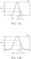
- FIGS. 11 A and 11 B graphs of examples of characteristics of the light source device according to the first embodiment.
- the horizontal axis in FIG. 11 A indicates the distance d 03 (arbitrary unit).
- the distance d 03 is defined as a distance from the first optical axis La 1 in the second plane PL 2 .
- the horizontal axis in FIG. 11 B indicates the distance d 04 (arbitrary unit).
- the distance d 04 is defined as a distance from the second optical axis La 2 in the second plane PL 2 .
- the vertical axis in FIG. 11 A indicates the intensity Ls 1 of the first light L 1 .
- the vertical axis in FIG. 11 B indicates the intensity Ls 2 of the second light L 2 .
- the intensity Ls 1 and the intensity Ls 2 are normalized values.
- the intensity Ls 1 of the first light L 1 when the distance d 03 is 0 is substantially “1”, and corresponds to the value (the first value v 1 ) on the first optical axis La 1 of the first light L 1 .
- the intensity Ls 2 of the second light L 2 when the distance d 04 is 0 is substantially “1”, and corresponds to the value (the second value v 2 ) on the second optical axis La 2 of the second light L 2 .
- the intensity Ls 1 of the first light L 1 at the position at the seventh distance d 7 is 0.7 times as great as the first value v 1 .
- the seventh distance d 7 refers to a distance between the first optical axis La 1 and the seventh position py 7 along the third axis Ax 3 .
- the intensity Ls 1 of the first light L 1 at the seventh position py 7 on the third axis Ax 3 is 0.7 times as great as the first value v 1 .
- the intensity Ls 1 of the first light L 1 at the position at the eighth distance d 8 is 0.5 times as great as the first value v 1 .
- the eighth distance d 8 refers to a distance between the first optical axis La 1 and the eighth position py 8 along the third axis Ax 3 .
- the intensity Ls 1 of the first light L 1 at the eighth position py 8 on the third axis Ax 3 is 0.5 times as great as the first value v 1 .
- the intensity Ls 1 of the first light L 1 at the position at the ninth distance d 9 is 0.3 times as great as the first value v 1 .
- the ninth distance d 9 refers to a distance between the first optical axis La 1 and the ninth position py 9 along the third axis Ax 3 .
- the intensity Ls 1 of the first light L 1 at the ninth position py 9 on the third axis Ax 3 is 0.3 times as great as the first value v 1 .
- the intensity Ls 2 of the second light L 2 at the position at the tenth distance d 10 is 0.7 times as great as the second value v 2 .
- the tenth distance d 10 refers to a distance between the second optical axis La 2 and the tenth position py 10 along the fourth axis Ax 4 .
- the intensity Ls 2 of the second light L 2 at the tenth position py 10 on the fourth axis Ax 4 is 0.7 times as great as the second value v 2 .
- the intensity Ls 2 of the second light L 2 at the position at the eleventh distance d 11 is 0.5 times as great as the second value v 2 .
- the eleventh distance d 11 refers to a distance between the second optical axis La 2 and the eleventh position py 11 along the fourth axis Ax 4 .
- the intensity Ls 2 of the second light L 2 at the eleventh position py 11 on the fourth axis Ax 4 is 0.5 times as great as the second value v 2 .
- the intensity Ls 2 of the second light L 2 at the position at the twelfth distance d 12 is 0.3 times as great as the second value v 2 .
- the twelfth distance d 12 is the distance between the second optical axis La 2 and the twelfth position py 12 along the fourth axis Ax 4 .
- the intensity Ls 2 of the second light L 2 at the twelfth position py 12 on the fourth axis Ax 4 is 0.3 times as great as the second value v 2 .
- a seventh ratio ⁇ 7 and an eighth ratio ⁇ 8 are employed.
- the seventh ratio ⁇ 7 as used herein refers to a ratio of the absolute value of the difference between the seventh distance d 7 and the ninth distance d 9 to the eighth distance d 8 .
- the eighth ratio ⁇ 8 as used herein refers to a ratio of the absolute value of the difference between the tenth distance d 10 and the twelfth distance d 12 to the eleventh distance d 11 .
- the seventh ratio ⁇ 7 and the eighth ratio ⁇ 8 are represented by:
- the distance distribution (or the position distribution) of the light intensity approximates “Gaussian distribution-like” distribution.
- the distance distribution (or the position distribution) of the light intensity is a “top-hat-like” distribution.
- the absolute value of the difference between the fifth ratio ⁇ 5 and the sixth ratio ⁇ 6 is set to be greater than the absolute value of the difference between the seventh ratio ⁇ 7 and the eighth ratio ⁇ 8 .
- the seventh ratio ⁇ 7 is 0.61 and the eighth ratio ⁇ 8 is 0.552.
- the difference (absolute value) between the fifth ratio and the sixth ratio is 0.298 and the difference (absolute value) between the seventh ratio and the eighth ratio is 0.058.
- the degree of the difference between the fifth ratio ⁇ 5 and the sixth ratio ⁇ 6 relating to the angular distribution is greater than the degree of the difference between the seventh ratio ⁇ 7 and the eighth ratio ⁇ 8 relating to the distance distribution.
- the intensity Ls 3 at the incident region 31 S of the condensing position 31 P is “top-hat-like” angular distribution in the direction corresponding to the second plane PL 2 .
- a light source device that exhibits light intensity distribution of improved uniformity can be provided.
- the absolute value between the fifth ratio ⁇ 5 and the sixth ratio ⁇ 6 is 0.3 or more.
- the sixth ratio ⁇ 6 is 0.297 or less.
- the angle ⁇ 03 at which the intensity Ls 1 of the first light L 1 becomes 0.135 times as great as the first value v 1 , from the first optical axis La 1 in the second plane PL 2 may be in a range of, for example, 3 degrees to 40 degrees.
- the first plane PL 1 extends along the fast axis Af of the first laser light and the second plane PL 2 extends along the slow axis As of the first laser light.
- FIG. 12 is a schematic diagram of the light source device according to the first embodiment.
- the focal length of the first lens 21 is referred to as the focal length fL.
- the length 1 ⁇ 2 as great as a length in the second plane PL 2 of the first light source 11 is referred to as the length y.
- the angular distribution width Ws in the second plane PL 2 of the second light L 2 emitted from the first lens 21 is, for example, greater than a value of 1.5 times as great as arctan (y/fL).
- the angular distribution width Ws corresponds to, for example, the angle ⁇ 04 , at which the intensity Ls 2 of the second light L 2 is 0.135 times as great as the second value v 2 of the intensity Ls 2 of the second light L 2 at the second optical axis La 2 .
- a reference example that uses a collimating optical system is considered.
- a component in a “Gaussian distribution-like” distribution along the slow axis As of the first light L 1 is deformed to become “top-hat-like” distribution.
- the angular distribution width Ws is 1.3 times or less as great as arctan (y/fL). In such a reference example, it is not easy to realize the angular distribution width Ws of at least 1.5 times as great as arctan (y/fL).
- embodiments of the present invention employs the technical idea of controlling the angular distribution.
- the angular distribution width Ws can be 1.5 times as great as arctan (y/fL) or greater.
- the “top-hat-like” distribution can be obtained while, for example, increasing the angle of light.
- FIGS. 13 A, 13 B, 14 A, 14 B, 15 A, 15 B, 16 A, and 16 B are graphs of examples of characteristics of the light source device according to the first embodiment.
- FIGS. 13 AS, 13 B, 14 A, and 14 B correspond to the characteristic along the first plane PL 1 and, for example, to the characteristic along the fast axis Af of the first light L 1 .
- FIGS. 15 A, 15 B, 16 A, and 16 B correspond to the characteristic along the second plane PL 2 and, for example, to the characteristic along the slow axis As of the first light L 1 .
- the horizontal axis in FIG. 13 A indicates the angle ⁇ 01 (degrees).
- the horizontal axis in FIG. 14 A indicates the distance d 01 (arbitrary unit).
- the horizontal axis in FIG. 14 B indicates the distance d 02 (arbitrary unit).
- the horizontal axis in FIG. 15 A indicates the angle ⁇ 03 (degrees).
- the horizontal axis in FIG. 15 B indicates the angle ⁇ 04 (degrees).
- the horizontal axis in FIG. 16 A indicates the distance d 03 (arbitrary unit).
- the horizontal axis in FIG. 16 B indicates the distance d 04 (arbitrary unit).
- the vertical axis in these graphs indicates the intensity Ls 1 of the first light L 1 or the intensity Ls 2 of the second light L 2 .
- the first ratio ⁇ 1 is 0.617 and the second ratio ⁇ 2 is 0.042.
- the third ratio ⁇ 3 is 0.576 and the fourth ratio ⁇ 4 is 0.573.
- the fifth ratio ⁇ 5 is 0.595 and the sixth ratio ⁇ 6 is 0.057.
- the seventh ratio ⁇ 7 is 0.610 and the eighth ratio ⁇ 8 is 0.552.
- FIGS. 17 A, 17 B, 18 A, 18 B, 19 A, 19 B, 20 A, and 20 B are each a graph of an example of a characteristic of the light source device according to the first embodiment.
- FIGS. 17 A, 17 B, 18 A, and 18 B correspond to the characteristic along the first plane PL 1 and, for example, to the characteristic along the fast axis Af of the first light L 1 .
- FIGS. 19 A, 19 B, 20 A, and 20 B correspond to the characteristic along the second plane PL 2 and, for example, to the characteristic along the slow axis As of the first light L 1 .
- the horizontal axis in FIG. 17 A indicates the angle ⁇ 01 (degrees).
- the horizontal axis in FIG. 17 B indicates the angle ⁇ 02 (degrees).
- the horizontal axis in FIG. 18 A indicates the distance d 01 (arbitrary unit).
- the horizontal axis in FIG. 18 B indicates the distance d 02 (arbitrary unit).
- the horizontal axis in FIG. 19 A indicates the angle ⁇ 03 (degrees).
- the horizontal axis in FIG. 19 B indicates the angle ⁇ 04 (degrees).
- the horizontal axis in FIG. 20 A indicates the distance d 03 (arbitrary unit).
- the horizontal axis in FIG. 20 B indicates the distance d 04 (arbitrary unit).
- the vertical axis in these graphs indicates the intensity Ls 1 of the first light L 1 or the intensity Ls 2 of the second light L 2 .
- the first ratio ⁇ 1 is 0.617 and the second ratio ⁇ 2 is 0.16.
- the third ratio ⁇ 3 is 0.576 and the fourth ratio ⁇ 4 is 0.573.
- the fifth ratio ⁇ 5 is 0.595 and the sixth ratio ⁇ 6 is 0.192.
- the seventh ratio ⁇ 7 is 0.610 and the eighth ratio ⁇ 8 is 0.552.
- the angular distribution of the intensity Ls 2 of the second light L 2 is “top-hat-like.”
- the incident region 31 S shows the light intensity distribution of improved uniformity.
- the quadrangular incident region 31 S shows the light intensity distribution of improved uniformity.
- One embodiment provides a light source device that exhibits light intensity distribution of improved uniformity.
- the light source device includes, for example, the first light source 11 that emits the first light L 1 , and the first lens 21 that includes the first surface 21 a and the second surface 21 b .
- the first light L 1 is incident on the first surface 21 a
- the second light L 2 is emitted from the second surface 21 b .
- the intensity Ls 1 of the first light L 1 has the first value v 1 on the first optical axis La 1 of the first light L 1 .
- the intensity Ls 1 of the first light L 1 in the direction at the first angle ⁇ 1 from the first optical axis La 1 is 0.7 times as great as the first value v 1 .
- the intensity Ls 1 of the first light L 1 in the direction at the second angle ⁇ 2 from the first optical axis La 1 is 0.5 times as great as the first value v 1 .
- the intensity Ls 1 of the first light L 1 in the direction at the third angle ⁇ 3 from the first optical axis La 1 is 0.3 times as great as the first value v 1 .
- the intensity Ls 2 of the second light L 2 has the second value v 2 on the second optical axis La 2 of the second light L 2 .
- the intensity Ls 2 of the second light L 2 in the direction at the fourth angle ⁇ 4 from the second optical axis La 2 is 0.7 times as great as the second value v 2 .
- the intensity Ls 2 of the second light L 2 in the direction at the fifth angle ⁇ 5 from the second optical axis La 2 is 0.5 times as great as the second value v 2 .
- the intensity Ls 2 of the second light L 2 in the direction at the sixth angle ⁇ 6 from the second optical axis La 2 is 0.3 times as great as the second value v 2 .
- the direction at the first angle ⁇ 1 , the direction at the second angle ⁇ 2 , the direction at the fourth angle ⁇ 4 , the direction at the fifth angle ⁇ 5 , and the direction at the sixth angle ⁇ 6 extend in the first plane PL 1 that includes the direction at the third angle ⁇ 3 and the first optical axis La 1 .
- the second ratio ⁇ 2 is set to be smaller than the first ratio ⁇ 1 .
- the first ratio ⁇ 1 refers to a ratio of the absolute value of the difference between the first angle ⁇ 1 and the third angle ⁇ 3 to the second angle ⁇ 2 .
- the second ratio ⁇ 2 refers to a ratio of the absolute value of the difference between the fourth angle ⁇ 4 and the sixth angle ⁇ 6 to the fifth angle ⁇ 5 .
- the angular distribution width Ws (see FIG. 12 ) extending in the first plane PL 1 of the second light L 2 is greater than a value 1.5 times as great as arctan (y/fL). “fL” is the focal length of the first lens 21 .
- y is a length of 1 ⁇ 2 of a length of the first light source 11 in the first plane PL 1 .
- the angular distribution width Ws corresponds to, for example, the angle ⁇ 02 , at which the intensity Ls 2 of the second light L 2 is 0.135 times as great as the second value v 2 of the intensity Ls 2 of the second light L 2 in the second optical axis La 2 .
- the shape of the second surface 21 b of the first lens 21 can be approximately expressed by the Mathematical Expression 1 described below.
- z is a sag value
- k is a conic coefficient
- r is a radius of curvature
- h is a center distance.
- A”, “B”, “C”, and “D” are coefficients.
- the first surface 21 a is a substantially flat surface.
- a shape of the second surface 21 b in the first plane PL 1 (for example, a shape along the fast axis Af) is expressed with the coefficients “r” of ⁇ 2.237, “k” of ⁇ 0.035, “A” of 8.4702 ⁇ 10 ⁇ 3 , “B” of 3.0393 ⁇ 10 ⁇ 3 , “C” of ⁇ 8.9688 ⁇ 10 ⁇ 4 , and “D” of 3.499910 ⁇ 4 .
- a shape in the second plane PL 2 of the second surface 21 b (for example, a shape extending along the slow axis As) is expressed with the coefficients “r” of ⁇ 7.284, “k” of 26.305, “A” of ⁇ 6.5943 ⁇ 10 ⁇ 1 , “B” of 1.6014, “C” of ⁇ 1.2907, and “D” of 0.
- the focal length fL is, for example, 4.76 mm.
- the divergence angle in the direction of the fast axis Af is 51 degrees and the divergence angle in the direction of the slow axis As is 9.5 degrees.
- the divergence angle corresponds to an angle between the first optical axis La 1 and the direction at the angle at which the intensity Ls 1 of the first light L 1 is 0.135 times as great as the first value v 1 of the intensity Ls 1 on the first optical axis La 1 .
- the divergence angle corresponds to, for example, the angular distribution width Ws.
- the angular distribution of the intensity Ls 1 of the first light L 1 is, for example, “Gaussian distribution-like” distribution.
- the Gaussian distribution is expressed by, for example, the second equation described below.
- the distribution when the super-Gaussian coefficient N is 1, the distribution is a general Gaussian distribution. When the super-Gaussian coefficient N is increased, the distribution becomes “top-hat-like” distribution.
- the super-Gaussian coefficient N of the angular distribution of the intensity Ls 2 of the second light L 2 is, for example, 2 or more. In one embodiment, the super-Gaussian coefficient N of the angular distribution of the intensity Ls 2 of the second light L 2 may be, for example, 4 or more.
- the curvature of at least a portion of the first surface 21 a is smaller than the curvature of at least a portion of the second surface 21 b .
- the first surface 21 a is a substantially flat surface
- the second surface 21 b may be a convex surface.
- FIG. 21 is a schematic diagram of a light source device according to a second embodiment.
- a light source device 120 includes a plurality of first light sources 11 and a plurality of first lenses 21 .
- the first light L 1 emitted from a corresponding one of the plurality of first light sources 11 is incident on one of the plurality of first lenses 21 .
- the first light L 1 emitted from another one of the plurality of first light sources 11 is incident on another one of the plurality of first lenses 21 .
- the direction from the corresponding one of the plurality of first light sources 11 to the another one of the plurality of first light sources 11 extends in, for example, the first plane PL 1 .
- the second light L 2 is emitted from each of the plurality of first lenses 21 .
- One of the plurality of second lights L 2 is emitted from the second surface 21 b of a corresponding one of the plurality of first lenses 21 .
- a plurality of second lights L 2 are incident on the optical element 31 .
- the plurality of third lights L 3 derived from the plurality of second lights L 2 is emitted from the optical element 31 .
- the plurality of third lights L 3 is condensed to the condensing position 31 P. At the condensing position 31 P, for example, the incident regions 31 S of the third lights L 3 are formed.
- the incident regions 31 S have, for example, a quadrangular shape.
- the plurality of first light sources 11 and the plurality of first lenses 21 may be arranged so as to correspond to the incident region 31 S.
- the first light L 1 emitted from a corresponding one of the plurality of first light sources 11 has a first divergence angle that is formed in the first plane PL 1 .
- the distance between the center of the corresponding one of the plurality of first light sources 11 and the center of another one of the plurality of first light sources 11 in the first plane PL 1 is greater than a value twice as great as the product of the focal length fL of the corresponding one of the plurality of first lenses 21 and the tangent of the first divergence angle. This allows for reducing incidence of light emitted from one of the plurality of first light sources 11 on the first lens 21 that corresponds to another one of the plurality of first light sources 11 in the first plane PL 1 .
- a plurality of first lights L 1 are incident on respective corresponding first lenses 21 .
- the direction from one of the plurality of first light sources 11 to another one of the plurality of first light sources 11 may extend in a plane that intersects the first plane PL 1 .
- the plane that intersects the first plane PL 1 may be, for example, the second plane PL 2 .
- the first light L 1 emitted from the corresponding one of the plurality of first light sources 11 has the first divergence angle formed in the plane (for example, the second plane) that intersects the first plane PL 1 .
- the distance between the center of the corresponding one of the plurality of first light sources 11 and the center of the another one of the plurality of first light sources 11 in the plane that intersects the first plane PL 1 is greater than a value twice as great as the product of the focal length fL of the corresponding one of the plurality of first lenses 21 and the tangent of the first divergence angle. This allows for reducing incidence of light emitted from one of the plurality of first light sources 11 on the first lens 21 corresponding to another one of the plurality of first light sources 11 , in the plane that intersects the first plane PL 1 .
- a plurality of beams of first light L 1 are incident on respective corresponding first lenses 21 .
- FIG. 22 is a schematic diagram of the light source device according to the second embodiment.
- a light source device 130 includes a plurality of first lenses 21 .
- the plurality of first lenses 21 are arranged, for example, in the X-axis direction and the Y-axis direction.
- a plurality of first light sources 11 (see FIG. 21 ) is provided so as to correspond to respective ones of the plurality of first lenses 21 .
- the plurality of first light sources 11 are also arranged, for example, in the X-axis direction and the Y-axis direction.
- the light source device 130 may further include the optical element 31 and the wavelength conversion member 32 .
- the second light L 2 is incident on the optical element 31 .
- the third light L 3 emitted from the optical element 31 is incident on the wavelength conversion member 32 .
- the second light L 2 condensed by the optical element 31 is incident on the wavelength conversion member 32 as the third light L 3 .
- the wavelength of the light emitted from the wavelength conversion member 32 is different from the wavelength of the second light L 2 (or the third light L 3 ).
- the second light L 2 is blue
- light emitted from the wavelength conversion member 32 is white light containing blue and yellow.
- the wavelength conversion member 32 is disposed at a first member 33 .
- the first member 33 is rotated by a driver 35 about a shaft 34 .
- the wavelength conversion member 32 is disposed at the first member 33 around the shaft 34 . Rotation of the first member 33 causes changes in the position where the third light L 3 is incident on the wavelength conversion member 32 . This allows for preventing light of excessively high intensity from being continuously incident on one position. For example, deterioration of the wavelength conversion member 32 and the like can be reduced.
- FIGS. 23 A and 23 B are schematic side views of the light source device according to one embodiment.
- FIGS. 23 A and 23 B illustrate one of a plurality of first light sources 11 and a corresponding one of a plurality of first lenses 21 .
- FIG. 23 A is a side view in the X-axis direction.
- FIG. 23 B is a side view in the Y-axis direction.
- a light source device 140 may include an optical component 15 .
- the optical component 15 is disposed, at least, between a corresponding one of the plurality of first light sources 11 and a corresponding one of the plurality of first lenses 21 .
- the optical component 15 may be disposed between a plurality of first light sources 11 and a plurality of first lenses 21 .
- the optical component 15 is formed of, for example, sapphire glass.
- the optical component 15 has a length Lz 15 (thickness) in the Z-axis direction of, for example, about 0.5 mm.
- One of the plurality of first lenses 21 has a length Lz 21 (thickness) in the Z-axis direction of, for example, about 2.0 mm.
- a distance Dz 1 between one of the plurality of first light sources 11 and the optical component 15 in the Z-axis direction is, for example, about 1.3 mm.
- a distance Dz 2 between the optical component 15 and one of the plurality of first lenses 21 in the Z-axis direction is about 0.3 mm.
- the plurality of first light sources 11 have a peak wavelength of about 455 nm.
- the emitted light In the Y-axis direction (the fast axis Af), the emitted light has a width of about 60 nm, the divergence angle of 22.75 degrees, and the super-Gaussian coefficient of 2.
- the emitted light In the X-axis direction (the slow axis As), the emitted light has a width of about 45 the divergence angle of 4.75 degrees, and the super-Gaussian coefficient of 2.
- the divergence angle is an angle (full width) at which the intensity of emitted light is 1/e 2 times as great as the peak value (where e is the Napier's constant).
- FIGS. 24 A and 24 B are schematic side views of an example of the light source device according to one embodiment.
- FIG. 24 A is a side view in the X-axis direction.
- FIG. 24 B is a side view in the Y-axis direction.
- two first light sources 11 are arranged in the Y-axis direction.
- seven first light sources 11 are arranged in the X-axis direction.
- a pitch pY of the plurality of light sources 11 in the Y-axis direction (the fast axis Af) is about 6.0 mm.
- a pitch pX of the plurality of light sources 11 in the X-axis direction (the slow axis As) is about 2.4 mm.
- the first lens 21 is provided so as to correspond to corresponding portions of the plurality of light sources 11 .
- the distance Dz 3 between the first lenses 21 and the optical element 31 along the Z-axis direction is about 2.5 mm.
- the distance Dz 3 may be determined according to the aperture of the optical element 31 , for example.
- the NA (numerical aperture) of the optical element 31 is about 0.65.
- the product code #49-101 available from Edmund Optics, Inc. may be employed.
- FIG. 25 is a schematic perspective view of a portion of the light source device according to one embodiment.
- FIG. 25 illustrates one example of a shape of one of a plurality of first lenses 21 .
- one of the plurality of first lenses 21 has a length in the Y-axis direction greater than its length in the X-axis direction.
- the shape of the second surface 21 b of one of the plurality of first lenses 21 is substantially expressed by Mathematical Expression 3 described below.
- the fourth-order aspheric coefficient is ⁇ 8.4702 ⁇ 10 ⁇ 3
- the sixth-order aspheric coefficient is 3.0393 ⁇ 10 ⁇ 3
- the eighth-order aspheric coefficient is ⁇ 8.9688 ⁇ 10 ⁇ 4
- the tenth-order aspheric coefficient is 3.499910 ⁇ 10′.
- the fourth-order aspheric coefficient is ⁇ 6.594 ⁇ 10 ⁇ 1
- the sixth-order aspheric coefficient is 1.601
- the eighth-order aspheric coefficient is ⁇ 1.2907
- the tenth-order aspheric coefficient is 0.
- Examples of the plurality of first lenses 21 include aspheric toroidal lenses and biconic Zernike lenses.
- Examples of a material of the plurality of first lenses 21 include K-PBK40 (for example, Ohara Corporation).
- FIG. 26 is a schematic perspective view of part of the light source device according to one embodiment.
- a plurality of first lenses 21 may be disposed on a base part 25 .
- the plurality of first lenses 21 and the base part 25 are included in the lens element 26 .
- the first surface 21 a (the incident surface) corresponds to aback surface of the base part 25 .
- the second surface 21 b corresponds to a front surface of each first lens 21 .
- the plurality of first lenses 21 and the base part 25 may be integrally formed.
- a material of the base part 25 may be the same as a material of the plurality of first lenses 21 .
- the plurality of first lenses 21 are arranged in a matrix in the X-axis direction and the Y-axis direction.
- the base part 25 has a length Lx in the X-axis direction of, for example, about 21.4 mm.
- the base part 25 has a length Ly in the Y-axis direction of, for example, about 21.4 mm.
- FIG. 27 is a schematic side view of a portion of the light source device according to one embodiment.
- the base part 25 has a thickness (a length Lz 25 in the Z-axis direction) of, for example, 1.5 mm.
- the length Lz which is the sum of the length in the Z-axis direction of the first lens 21 and the length Lz 25 in the Z-axis direction of the base part 25 is, for example, 2.85 mm.
- the values relating to the length (thickness) and the distance are examples and can be changed in one embodiment.
- a light source device that exhibits light intensity distribution of improved uniformity can be provided.
- perpendicular and parallel encompass not only an exactly perpendicular configuration and an exactly parallel configuration but also configurations slightly deviated from these configuration due to manufacturing variations, etc. That is, the terms “perpendicular” and “parallel” encompass substantially perpendicular and substantially parallel configurations, respectively.
- the present invention is not limited to these specific examples.
- the specific structures of the light sources, the lenses, the optical element, and the wavelength conversion member may be appropriately selected from known art by a person skilled in the art, and such specific configurations are included in the light source device are within the scope of the present invention so long as a person skilled in the art can similarly implement the structure the invention and similar effects can be obtained.
Landscapes
- Engineering & Computer Science (AREA)
- Physics & Mathematics (AREA)
- General Engineering & Computer Science (AREA)
- Optics & Photonics (AREA)
- Microelectronics & Electronic Packaging (AREA)
- General Physics & Mathematics (AREA)
- Lenses (AREA)
Abstract
Description
α1=|θ1−θ3|/θ2
α2=|θ4−θ6|/θ5
α3=|d1−d3|/d2
α4=|d4−d6|/d5
α5=|θ7-θ9|/θ8
α6=|θ10-θ12|/θ11
-
- α7=|d7−d9|/d8
- α8=|d10−d12|/d11
Claims (20)
Applications Claiming Priority (6)
| Application Number | Priority Date | Filing Date | Title |
|---|---|---|---|
| JP2019209373 | 2019-11-20 | ||
| JP2019-209373 | 2019-11-20 | ||
| JPJP2019-209373 | 2019-11-20 | ||
| JPJP2020-102260 | 2020-06-12 | ||
| JP2020102260A JP7579499B2 (en) | 2019-11-20 | 2020-06-12 | Light source |
| JP2020-102260 | 2020-06-12 |
Publications (2)
| Publication Number | Publication Date |
|---|---|
| US20210148525A1 US20210148525A1 (en) | 2021-05-20 |
| US11560987B2 true US11560987B2 (en) | 2023-01-24 |
Family
ID=75908109
Family Applications (1)
| Application Number | Title | Priority Date | Filing Date |
|---|---|---|---|
| US17/099,453 Active 2041-08-04 US11560987B2 (en) | 2019-11-20 | 2020-11-16 | Light source device |
Country Status (1)
| Country | Link |
|---|---|
| US (1) | US11560987B2 (en) |
Citations (14)
| Publication number | Priority date | Publication date | Assignee | Title |
|---|---|---|---|---|
| US3476463A (en) * | 1965-05-11 | 1969-11-04 | Perkin Elmer Corp | Coherent light optical system yielding an output beam of desired intensity distribution at a desired equiphase surface |
| JPH0199017A (en) | 1987-10-12 | 1989-04-17 | Fuji Electric Co Ltd | Equalizing device for gaussian distribution light beam in optical system |
| US5148317A (en) * | 1991-06-24 | 1992-09-15 | The United States Of America As Represented By The Secretary Of The Air Force | Diffractive optical element for collimating and redistributing Gaussian input beam |
| JPH11258544A (en) | 1998-03-09 | 1999-09-24 | Fujitsu Ltd | Light intensity conversion element, optical device, and optical disk device |
| JP2001125040A (en) | 1999-10-27 | 2001-05-11 | Minolta Co Ltd | Laser irradiation optical system |
| JP2002198568A (en) | 2000-12-27 | 2002-07-12 | Sunx Ltd | Light projecting unit and photoelectric sensor |
| US6437284B1 (en) * | 1999-06-25 | 2002-08-20 | Mitsubishi Denki Kabushiki Kaisha | Optical system and apparatus for laser heat treatment and method for producing semiconductor devices by using the same |
| JP2003001472A (en) | 2001-06-21 | 2003-01-08 | Matsushita Electric Ind Co Ltd | Laser processing apparatus and method |
| US6531677B2 (en) * | 2000-10-06 | 2003-03-11 | Hitachi Via Mechanics, Ltd. | Method and apparatus for drilling printed wiring boards |
| JP2004252275A (en) | 2003-02-21 | 2004-09-09 | Sumitomo Electric Ind Ltd | Aspherical Fourier type homogenizer optical system |
| US20050094288A1 (en) | 2003-10-31 | 2005-05-05 | Sumitomo Electric Industries, Ltd. | Tilt error reducing aspherical single lens homogenizer |
| US8427752B2 (en) * | 2009-04-22 | 2013-04-23 | Olympus Corporation | Illumination apparatus and microscope having the same |
| JP2013130835A (en) | 2011-12-22 | 2013-07-04 | Sharp Corp | Homogenizer, homogenizer device and illuminating device |
| US9285593B1 (en) * | 2013-12-20 | 2016-03-15 | AdlOptica Optical Systems GmbH | Method and apparatus for shaping focused laser beams |
-
2020
- 2020-11-16 US US17/099,453 patent/US11560987B2/en active Active
Patent Citations (17)
| Publication number | Priority date | Publication date | Assignee | Title |
|---|---|---|---|---|
| US3476463A (en) * | 1965-05-11 | 1969-11-04 | Perkin Elmer Corp | Coherent light optical system yielding an output beam of desired intensity distribution at a desired equiphase surface |
| JPH0199017A (en) | 1987-10-12 | 1989-04-17 | Fuji Electric Co Ltd | Equalizing device for gaussian distribution light beam in optical system |
| US5148317A (en) * | 1991-06-24 | 1992-09-15 | The United States Of America As Represented By The Secretary Of The Air Force | Diffractive optical element for collimating and redistributing Gaussian input beam |
| JPH11258544A (en) | 1998-03-09 | 1999-09-24 | Fujitsu Ltd | Light intensity conversion element, optical device, and optical disk device |
| US6201229B1 (en) | 1998-03-09 | 2001-03-13 | Fujitsu Limited | Light intensity converter |
| US6437284B1 (en) * | 1999-06-25 | 2002-08-20 | Mitsubishi Denki Kabushiki Kaisha | Optical system and apparatus for laser heat treatment and method for producing semiconductor devices by using the same |
| US6400745B1 (en) | 1999-10-27 | 2002-06-04 | Minolta Co., Ltd. | Laser radiating optical system |
| JP2001125040A (en) | 1999-10-27 | 2001-05-11 | Minolta Co Ltd | Laser irradiation optical system |
| US6531677B2 (en) * | 2000-10-06 | 2003-03-11 | Hitachi Via Mechanics, Ltd. | Method and apparatus for drilling printed wiring boards |
| JP2002198568A (en) | 2000-12-27 | 2002-07-12 | Sunx Ltd | Light projecting unit and photoelectric sensor |
| JP2003001472A (en) | 2001-06-21 | 2003-01-08 | Matsushita Electric Ind Co Ltd | Laser processing apparatus and method |
| JP2004252275A (en) | 2003-02-21 | 2004-09-09 | Sumitomo Electric Ind Ltd | Aspherical Fourier type homogenizer optical system |
| US20050094288A1 (en) | 2003-10-31 | 2005-05-05 | Sumitomo Electric Industries, Ltd. | Tilt error reducing aspherical single lens homogenizer |
| JP2005134681A (en) | 2003-10-31 | 2005-05-26 | Sumitomo Electric Ind Ltd | Aspheric homogenizer with reduced tilt error |
| US8427752B2 (en) * | 2009-04-22 | 2013-04-23 | Olympus Corporation | Illumination apparatus and microscope having the same |
| JP2013130835A (en) | 2011-12-22 | 2013-07-04 | Sharp Corp | Homogenizer, homogenizer device and illuminating device |
| US9285593B1 (en) * | 2013-12-20 | 2016-03-15 | AdlOptica Optical Systems GmbH | Method and apparatus for shaping focused laser beams |
Also Published As
| Publication number | Publication date |
|---|---|
| US20210148525A1 (en) | 2021-05-20 |
Similar Documents
| Publication | Publication Date | Title |
|---|---|---|
| US9404638B2 (en) | Optical element and illumination unit | |
| EP2690484B1 (en) | Head-up display device | |
| US11378877B2 (en) | Homogenizer, illuminating optical system, and illuminator | |
| US10174900B2 (en) | Lighting apparatus for vehicles | |
| US9857044B2 (en) | Lighting apparatus and automobile having lighting apparatus mounted therein | |
| US20120099310A1 (en) | Light guide module with adjustable contour surface illumination | |
| ITTO940773A1 (en) | LIGHT GUIDE LIGHTING SYSTEM SUITABLE TO REALIZE A THIN LIGHTING DEVICE | |
| WO2021147827A1 (en) | Diffuser device | |
| US20110002042A1 (en) | Line generator | |
| EP3392550A1 (en) | Optical element and led lighting device | |
| US9677734B2 (en) | Optical device, in particular for a motor vehicle | |
| US20190173255A1 (en) | Laser Diode Device and a Projector Using Same | |
| US11560987B2 (en) | Light source device | |
| US10429551B2 (en) | Microlens array | |
| US10663741B2 (en) | Beam intensity conversion optical system and beam intensity conversion lens | |
| US9903992B2 (en) | Lamp | |
| US7195387B2 (en) | Device and method for emitting light with increased brightness using diffractive grating pattern | |
| JP2005121938A (en) | Diffraction grating with polarization control film, and diffraction optical device using same | |
| JPH0661566A (en) | Optical device and manufacturing method thereof | |
| US20210239968A1 (en) | Two-lens optical system, beam combining module, projector, and method for assembling two-lens optical system | |
| JP7579499B2 (en) | Light source | |
| JP2003262832A (en) | Diffraction compensation using reflector with pattern | |
| US11187915B2 (en) | Parallel light generation device | |
| US12483001B2 (en) | Lighting optical system | |
| US11402551B2 (en) | Optical lens for a photodiode-equipped device |
Legal Events
| Date | Code | Title | Description |
|---|---|---|---|
| AS | Assignment |
Owner name: NICHIA CORPORATION, JAPAN Free format text: ASSIGNMENT OF ASSIGNORS INTEREST;ASSIGNORS:ARUGA, TAKANORI;NAGAHASHI, AKIRA;REEL/FRAME:054381/0321 Effective date: 20201111 |
|
| FEPP | Fee payment procedure |
Free format text: ENTITY STATUS SET TO UNDISCOUNTED (ORIGINAL EVENT CODE: BIG.); ENTITY STATUS OF PATENT OWNER: LARGE ENTITY |
|
| STPP | Information on status: patent application and granting procedure in general |
Free format text: APPLICATION DISPATCHED FROM PREEXAM, NOT YET DOCKETED |
|
| STPP | Information on status: patent application and granting procedure in general |
Free format text: DOCKETED NEW CASE - READY FOR EXAMINATION |
|
| STPP | Information on status: patent application and granting procedure in general |
Free format text: NOTICE OF ALLOWANCE MAILED -- APPLICATION RECEIVED IN OFFICE OF PUBLICATIONS |
|
| STPP | Information on status: patent application and granting procedure in general |
Free format text: PUBLICATIONS -- ISSUE FEE PAYMENT VERIFIED |
|
| STCF | Information on status: patent grant |
Free format text: PATENTED CASE |